kbox b-202-cfl
TRANSCRIPT

USER GUIDE
www.kontron.com // 1
KBox B-202-CFL Doc. User Guide, Rev 1.1
Doc. ID: 1065-5686

KBox B-202-CFL - User Guide, Rev 1.1
www.kontron.com // 2
This page has been intentionally left blank

KBox B-202-CFL - User Guide, Rev 1.1
www.kontron.com // 3
KBOX B-202-CFL - USER GUIDE
Disclaimer Kontron would like to point out that the information contained in this user guide may be subject to alteration, particularly as a result of the constant upgrading of Kontron products. This document does not entail any guarantee on the part of Kontron with respect to technical processes described in the user guide or any product characteristics set out in the user guide. Kontron assumes no responsibility or liability for the use of the described product(s), conveys no license or title under any patent, copyright or mask work rights to these products and makes no representations or warranties that these products are free from patent, copyright or mask work right infringement unless otherwise specified. Applications that are described in this user guide are for illustration purposes only. Kontron makes no representation or warranty that such application will be suitable for the specified use without further testing or modification. Kontron expressly informs the user that this user guide only contains a general description of processes and instructions which may not be applicable in every individual case. In cases of doubt, please contact Kontron.
This user guide is protected by copyright. All rights are reserved by Kontron. No part of this document may be reproduced, transmitted, transcribed, stored in a retrieval system, or translated into any language or computer language, in any form or by any means (electronic, mechanical, photocopying, recording, or otherwise), without the express written permission of Kontron. Kontron points out that the information contained in this user guide is constantly being updated in line with the technical alterations and improvements made by Kontron to the products and thus this user guide only reflects the technical status of the products by Kontron at the time of publishing.
Brand and product names are trademarks or registered trademarks of their respective owners.
©2020 by Kontron S&T AG
Kontron S&T AG
Lise-Meitner-Str. 3-5 86156 Augsburg Germany www.kontron.com

KBox B-202-CFL - User Guide, Rev 1.1
www.kontron.com // 4
Intended Use
This embedded Box PC, sold by Kontron, is part of Kontron’s B-Series intended for high performance, low noises needs with 24/7 operation and long-term availability. The product can operate in a temperature range from 0°C to plus 45°C; and when stored can withstand temperatures from minus 20°C to plus 80°C; a humidity of 10 to 93 percent does not affect the function of the product. The KBox B-202-CFL is a high performance BoxPC designed for demanding applications such as high-end image processing, SCADA/MES applications, artificial intelligence and machine learning. In addition, the KBox B-202-CFL meets Class B meets stricter RFI limits makes it suitable not only for use in industrial environments, but also for use in residential and business areas or in their immediate vicinity, making the KBox B-202-CFL the ideal computer for architecture and graphics offices as well as music studios.
THIS PRODUCT IS NOT DESIGNED, MANUFACTURED OR INTENDED FOR USE OR RESALE FOR THE OPERATION OF APPLICATION IN A HAZARDOUS ENVIRONMENT, OR REQUIRING FAIL-SAFE PERFORMANCE, OR IN WHICH THE FAILURE OF PRODUCTS COULD LEAD DIRECTLY TO DEATH, PERSONAL INJURY, OR SEVERE PHYSICAL OR ENVIRONMENTAL DAMAGE (COLLECTIVELY "HIGH RISK APPLICATIONS").
You understand and agree that your use of Kontron products as a component in High Risk Applications is entirely at your own risk. To minimize the risks associated with your systems and applications, you must provide adequate design and operating safeguards. You are responsible to ensure that your systems (and any Kontron hardware or software products incorporated in your systems) meet all applicable requirements. Unless otherwise stated in the product documentation, the Kontron product is not provided with error-tolerance capabilities and therefore cannot be deemed as being engineered, manufactured or setup to be compliant for implementation or for resale as a component in High Risk Applications. All application and safety related information in this document (including application descriptions, suggested safety measures, suggested Kontron products, and other materials) is provided for reference only.

KBox B-202-CFL - User Guide, Rev 1.1
www.kontron.com // 5
Revision History
Revision Brief Description of Changes Date of Issue Author/Editor
1.0 Initial Version 2020-May-13 CW
1.1 Changes to BIOS Update procedure 2020-Jul-06 CW
Terms and Conditions Kontron warrants products in accordance with defined regional warranty periods. For more information about warranty compliance and conformity, and the warranty period in your region, visit http://www.kontron.com/terms-and-conditions.
Kontron sells products worldwide and declares regional General Terms & Conditions of Sale, and Purchase Order Terms & Conditions. Visit http://www.kontron.com/terms-and-conditions.
For contact information, refer to the corporate offices contact information on the last page of this user guide or visit our website CONTACT US.
Customer Support Find Kontron contacts by visiting: http://www.kontron.com/support.
Customer Service As a trusted technology innovator and global solutions provider, Kontron extends its embedded market strengths into a services portfolio allowing companies to break the barriers of traditional product lifecycles. Proven product expertise coupled with collaborative and highly-experienced support enables Kontron to provide exceptional peace of mind to build and maintain successful products.
For more details on Kontron’s service offerings such as: enhanced repair services, extended warranty, Kontron training academy, and more visit http://www.kontron.com/support-and-services/services.
Customer Comments If you have any difficulties using this user guide, discover an error, or just want to provide some feedback, contact Kontron support. Detail any errors you find. We will correct the errors or problems as soon as possible and post the revised user guide on our website.

KBox B-202-CFL - User Guide, Rev 1.1
www.kontron.com // 6
Symbols The following symbols may be used in this user guide
DANGER indicates a hazardous situation which, if not avoided,
will result in death or serious injury.
WARNING indicates a hazardous situation which, if not avoided,
could result in death or serious injury.
NOTICE indicates a property damage message.
CAUTION indicates a hazardous situation which, if not avoided,
may result in minor or moderate injury.
Electric Shock!
This symbol and title warn of hazards due to electrical shocks (> 60 V) when touching products or parts of products. Failure to observe the precautions indicated and/or prescribed by the law may endanger your life/health and/or result in damage to your material.
ESD Sensitive Device!
This symbol and title inform that the electronic boards and their components are sensitive to static electricity. Care must therefore be taken during all handling operations and inspections of this product in order to ensure product integrity at all times.
HOT Surface!
Do NOT touch! Allow to cool before servicing.
Laser!
This symbol inform of the risk of exposure to laser beam and light emitting devices (LEDs) from an electrical device. Eye protection per manufacturer notice shall review before servicing.
This symbol indicates general information about the product and the user guide.
This symbol also indicates detail information about the specific product configuration.
This symbol precedes helpful hints and tips for daily use.

KBox B-202-CFL – User Guide, Rev 1.1
www.kontron.com // 7
For Your Safety Your new Kontron product was developed and tested carefully to provide all features necessary to ensure its compliance with electrical safety requirements. It was also designed for a long fault-free life. However, the life expectancy of your product can be drastically reduced by improper treatment during unpacking and installation. Therefore, in the interest of your own safety and of the correct operation of your new Kontron product, you are requested to conform with the following guidelines.
High Voltage Safety Instructions
As a precaution and in case of danger, the power connector must be easily accessible. The power connector is the product’s main disconnect device.
Warning
All operations on this product must be carried out by sufficiently skilled personnel only.
Electric Shock!
Before installing a non hot-swappable Kontron product into a system always ensure that your mains power is switched off. This also applies to the installation of piggybacks. Serious electrical shock hazards can exist during all installation, repair, and maintenance operations on this product. Therefore, always unplug the power cable and any other cables which provide external voltages before performing any work on this product.
Earth ground connection to vehicle’s chassis or a central grounding point shall remain connected. The earth ground cable shall be the last cable to be disconnected or the first cable to be connected when performing installation or removal procedures on this product.
Special Handling and Unpacking Instruction
ESD Sensitive Device!
Electronic boards and their components are sensitive to static electricity. Therefore, care must be taken during all handling operations and inspections of this product, in order to ensure product integrity at all times.
Handling and operation of the product is permitted only for trained personnel aware of the
associated dangers, within a work place that is access controlled and fulfills all necessary technical and environmental requirements. Follow the “General Safety Instructions for IT Equipment” supplied with the product.
Do not handle this product out of its protective enclosure while it is not used for operational purposes unless it is otherwise protected.
Whenever possible, unpack or pack this product only at EOS/ESD safe work stations. Where a safe work station is not guaranteed, it is important for the user to be electrically discharged before touching the product with his/her hands or tools. This is most easily done by touching a metal part of your system housing.
It is particularly important to observe standard anti-static precautions when changing piggybacks, ROM devices, jumper settings etc. If the product contains batteries for RTC or memory backup, ensure that the product is not placed on conductive surfaces, including anti-static plastics or sponges. They can cause short circuits and damage the batteries or conductive circuits on the product.

KBox B-202-CFL - User Guide, Rev 1.1
www.kontron.com // 8
Lithium Battery Precautions
If your product is equipped with a lithium battery, take the following precautions when replacing the battery.
Danger of explosion if the battery is replaced incorrectly.
Replace only with same or equivalent battery type recommended by the manufacturer.
Dispose of used batteries according to the manufacturer’s instructions.
General Instructions on Usage In order to maintain Kontron’s product warranty, this product must not be altered or modified in any way. Changes or modifications to the product, that are not explicitly approved by Kontron and described in this user guide or received from Kontron Support as a special handling instruction, will void your warranty. This product should only be installed in or connected to systems that fulfill all necessary technical and specific environmental requirements. This also applies to the operational temperature range of the specific board version that must not be exceeded. In performing all necessary installation and application operations, only follow the instructions supplied by the present user guide. Keep all the original packaging material for future storage or warranty shipments. If it is necessary to store or ship the product then repack it in the same manner as it was delivered. Special care is necessary when handling or unpacking the product. See Special Handling and Unpacking Instruction.
Quality and Environmental Management Kontron aims to deliver reliable high-end products designed and built for quality, and aims to complying with environmental laws, regulations, and other environmentally oriented requirements. For more information regarding Kontron’s quality and environmental responsibilities, visit http://www.kontron.com/about-kontron/corporate-responsibility/quality-management.
Disposal and Recycling
Kontron’s products are manufactured to satisfy environmental protection requirements where possible. Many of the components used are capable of being recycled. Final disposal of this product after its service life must be accomplished in accordance with applicable country, state, or local laws or regulations.
WEEE Compliance
The Waste Electrical and Electronic Equipment (WEEE) Directive aims to:
Reduce waste arising from electrical and electronic equipment (EEE)
Make producers of EEE responsible for the environmental impact of their products, especially when the product become waste
Encourage separate collection and subsequent treatment, reuse, recovery, recycling and sound environmental disposal of EEE
Improve the environmental performance of all those involved during the lifecycle of EEE
Environmental protection is a high priority with Kontron.
Kontron follows the WEEE directive

KBox B-202-CFL - User Guide, Rev 1.1
www.kontron.com // 9
Table of Contents Symbols ................................................................................................................................................................................................................. 6 For Your Safety ................................................................................................................................................................................................... 7 High Voltage Safety Instructions .................................................................................................................................................................. 7 Special Handling and Unpacking Instruction ............................................................................................................................................ 7 Lithium Battery Precautions .......................................................................................................................................................................... 8 General Instructions on Usage ..................................................................................................................................................................... 8 Quality and Environmental Management ................................................................................................................................................ 8 Disposal and Recycling .................................................................................................................................................................................... 8 WEEE Compliance.............................................................................................................................................................................................. 8 Table of Contents............................................................................................................................................................................................... 9 List of Tables ...................................................................................................................................................................................................... 11 List of Figures ..................................................................................................................................................................................................... 11 1/ General Safety Instructions for IT Equipment ......................................................................................................................... 13 1.1. Electrostatic Discharge (ESD) Precautions ....................................................................................................................................... 14 1.2. Grounding Methods .................................................................................................................................................................................. 14 1.3. Instructions for the Lithium Battery ................................................................................................................................................... 15 2/ Introduction ......................................................................................................................................................................................... 16 3/ Scope of Delivery ............................................................................................................................................................................... 17 3.1. Packaging ..................................................................................................................................................................................................... 17 3.2. Type Label and Product Identification ............................................................................................................................................... 17 4/ Product Overview .............................................................................................................................................................................. 18 4.1. Front Side View .......................................................................................................................................................................................... 19 4.1.1. Front Connectors and Buttons .......................................................................................................................................................... 19 4.2. Rear Side Views ........................................................................................................................................................................................ 20 4.2.1. Rear Panel Connectors ........................................................................................................................................................................ 21 4.3. Left and Right Side Views ..................................................................................................................................................................... 25 4.4. Top Cover and Bottom Side Views .................................................................................................................................................... 26 5/ System Extension ............................................................................................................................................................................. 27 5.1. System Storage and Expansion Card Combinations .................................................................................................................... 27 5.2. Mass Storage Devices ............................................................................................................................................................................ 29 5.2.1. 2.5” SSD Drive ......................................................................................................................................................................................... 29 5.2.2. 2.5” SSD dual M.2 RAID Module ....................................................................................................................................................... 29 5.2.3. Internal 2.5” SSD Drives ...................................................................................................................................................................... 29 5.2.4. On-board M.2 SSD Module ............................................................................................................................................................... 29 5.3. Expansion Cards....................................................................................................................................................................................... 30 5.3.1. PCIe Expansion Cards .......................................................................................................................................................................... 30 5.3.2. On-board mPCIE Expansion Card .................................................................................................................................................... 30 6/ Accessing Components .................................................................................................................................................................... 31 6.1. Removing and Installing the Top Cover ............................................................................................................................................. 31 6.1.1. Installing and Removing an On-board mPCIe Expansion Card .............................................................................................. 33 6.1.2. Installing and Removing an On-board M.2 SSD Module .......................................................................................................... 33 6.2. Installing and Removing a PCIe Card ................................................................................................................................................ 34 6.3. Opening and Closing the Drive Bay Cover ....................................................................................................................................... 36 6.3.1. Installing and Removing a 2.5” SSD Drive ..................................................................................................................................... 37 6.3.2. Installing and Configuring the 2.5” SSD dual M.2 RAID Module ............................................................................................ 38 6.3.3. Replacing a M.2 SSD Module ............................................................................................................................................................ 40

KBox B-202-CFL - User Guide, Rev 1.1
www.kontron.com // 10
7/ Thermal Considerations ................................................................................................................................................................. 42 7.1. Active Cooling ............................................................................................................................................................................................ 42 7.2. Mount Orientation ................................................................................................................................................................................... 43 7.3. Minimum Clearance (Keep Out Area) ................................................................................................................................................ 43 7.4. Third Party Components ....................................................................................................................................................................... 43 8/ Installation Instructions ................................................................................................................................................................. 44 8.1. Chassis Feet ............................................................................................................................................................................................... 45 8.1.1. Chassis Feet Mount (option) ............................................................................................................................................................. 45 8.2. Mounting Brackets (option) ................................................................................................................................................................. 46 8.2.1. Mounting Brackets on a Desktop .................................................................................................................................................... 48 8.2.2. Mounting Brackets on a Wall ........................................................................................................................................................... 49 8.3. Connecting the Wi-Fi Antenna (option) ........................................................................................................................................... 50 9/ Starting Up............................................................................................................................................................................................ 51 9.1. Connecting to DC Power Supply ........................................................................................................................................................... 51 9.2. Switching On /Off .................................................................................................................................................................................... 52 9.3. Operating System (OS) and Hardware Component Drivers ...................................................................................................... 52 10/ Technical Data ................................................................................................................................................................................... 53 10.1. Block Diagrams ....................................................................................................................................................................................... 53 10.2. Technical Specification ........................................................................................................................................................................ 55 10.3. Mechanical Specification .................................................................................................................................................................... 58 10.3.1. Dimension Diagrams .......................................................................................................................................................................... 58 10.4. Environmental Specification ............................................................................................................................................................. 60 10.5. Directives and Standards ..................................................................................................................................................................... 61 10.6. Power Specification .............................................................................................................................................................................. 62 10.6.1. Power Consumption .......................................................................................................................................................................... 62 10.6.2. Power Protection ............................................................................................................................................................................... 63 10.6.3. Ground ................................................................................................................................................................................................... 63 11/ External Interface - Pin Assignments ........................................................................................................................................ 64 11.1. DC IN Power Connector Pin Assignment ......................................................................................................................................... 64 11.2. USB 3.1 Gen 1 Port & USB 3.1 Gen 2 Pin Assignment .................................................................................................................... 64 11.3. USB 2.0 Port Pin Assignment .............................................................................................................................................................. 65 11.4. LAN Connector Pin Assignment ......................................................................................................................................................... 65 11.5. Display Port (DP) V1.2 Connector Pin Assignment....................................................................................................................... 66 11.6. DVI-D Connector Pin Assignment ..................................................................................................................................................... 66 11.7. PS/2 Keyboard Connector Pin Assignment .................................................................................................................................... 67 11.8. PS/2 Mouse Connector Pin Assignment ......................................................................................................................................... 67 11.9. Audio Line-out and Audio Line-in Connector Pin Assignment ................................................................................................ 67 11.10. Serial Port Connector Pin Assignment .......................................................................................................................................... 68 12/ BIOS ........................................................................................................................................................................................................ 69 12.1. Starting the uEFI BIOS ........................................................................................................................................................................... 69 12.2. BIOS Update ............................................................................................................................................................................................. 70 13/ RAID ......................................................................................................................................................................................................... 71 13.1. iRAID Utility Software ............................................................................................................................................................................. 71 13.1.1. Settings .................................................................................................................................................................................................... 71 13.1.2. Notifications ......................................................................................................................................................................................... 72 13.1.3. Events ..................................................................................................................................................................................................... 72 13.2. Chipset RAID ............................................................................................................................................................................................ 72 14/ Technical Support ............................................................................................................................................................................. 73 14.1. Returning Defective Merchandise .................................................................................................................................................... 73

KBox B-202-CFL - User Guide, Rev 1.1
www.kontron.com // 11
15/ Storage, Transportation and Maintenance ............................................................................................................................. 74 15.1. Storage ....................................................................................................................................................................................................... 74 15.2. Transportation ........................................................................................................................................................................................ 74 15.3. Maintenance ............................................................................................................................................................................................ 74 15.3.1. Replacing the Lithium Battery ........................................................................................................................................................ 74 16/ Warranty ...............................................................................................................................................................................................75 16.1. Limitation/Exemption from Warranty Obligation ........................................................................................................................ 75 Appendix A: List of Acronyms ..................................................................................................................................................................... 76 About Kontron ................................................................................................................................................................................................... 77
List of Tables Table 1: Scope of Delivery .............................................................................................................................................................................. 17 Table 2: Accessories ........................................................................................................................................................................................ 17 Table 3: M.2 SSD Module and mPCIe Expansion Card Combinations ............................................................................................. 28 Table 4: Storage and Expansion Card Combinations .......................................................................................................................... 28 Table 5: RAID Module Jumper Settings..................................................................................................................................................... 39 Table 6: Motherboard Specification .......................................................................................................................................................... 55 Table 7: Processor Specification ................................................................................................................................................................ 55 Table 8: Storage Specification .................................................................................................................................................................... 55 Table 9: External Interface Specifications .............................................................................................................................................. 56 Table 10: Internal Expansion Slots ............................................................................................................................................................. 56 Table 11: External Expansion Slots ............................................................................................................................................................. 57 Table 12: Software Specification ................................................................................................................................................................. 57 Table 13: Chassis Specification .................................................................................................................................................................... 57 Table 14: Mechanical Specifications ......................................................................................................................................................... 58 Table 15: Environmental Specification ..................................................................................................................................................... 60 Table 16: Directives and Standards Compliance .................................................................................................................................... 61 Table 17: Power Supply Electrical Specification .................................................................................................................................... 62 Table 18: Power Consumption Estimation .............................................................................................................................................. 62 Table 19: Power Supply Protection Features ......................................................................................................................................... 63 Table 20: DC Power Jack Pin Assignment ................................................................................................................................................ 64 Table 21: USB 3.1 Connector Pin Assignment ......................................................................................................................................... 64 Table 22: USB 2.0 Connector Pin Assignment ........................................................................................................................................ 65 Table 23: LAN (GbE) Connector Pin Assignment ................................................................................................................................... 65 Table 24: LAN Link Activity ........................................................................................................................................................................... 65 Table 25: Display Port (DP) Connector Pin Assignment ..................................................................................................................... 66 Table 26: DVI-D Connector Pin Assignment ........................................................................................................................................... 66 Table 27: PS/2 Keyboard Connector Pin Assignment .......................................................................................................................... 67 Table 28: PS/2 Mouse Connector Pin Assignment ............................................................................................................................... 67 Table 29: Audio Line-OUT Audio Line-IN Pin Assignment .................................................................................................................. 67 Table 30: Serial Interface COM port (RS232) Connector Pin Assignment .................................................................................... 68 Table 31: Navigation Hot Keys Available in the Legend Bar .............................................................................................................. 70 Table 32: RAID Options with Features ....................................................................................................................................................... 71 Table 33: S.M.A.R.T. Information Memory Attributes Examples ....................................................................................................... 71 Table 34: Notifications Examples .............................................................................................................................................................. 72 Table 35: Event List Examples .................................................................................................................................................................... 72 Table 36: List of Acronyms ........................................................................................................................................................................... 76
List of Figures Figure 1: KBox B-202-CFL .............................................................................................................................................................................. 16 Figure 2: Type Labels....................................................................................................................................................................................... 17 Figure 3: KBox B-202-CFL Overview .......................................................................................................................................................... 18

KBox B-202-CFL - User Guide, Rev 1.1
www.kontron.com // 12
Figure 4: Front Panel ....................................................................................................................................................................................... 19 Figure 5: Rear Panel KBox B-202-CFL Smart ......................................................................................................................................... 20 Figure 6: Rear Panal KBox B-202-CFL Value ........................................................................................................................................... 21 Figure 7: Left Side and Right Side ............................................................................................................................................................... 25 Figure 8: Top View ........................................................................................................................................................................................... 26 Figure 9: Bottom View .................................................................................................................................................................................... 26 Figure 10: System Expansion Options ....................................................................................................................................................... 27 Figure 11: Top Cover Fastening Screws .................................................................................................................................................... 32 Figure 12: Holding Brackets .......................................................................................................................................................................... 32 Figure 13: PCIe Expansion Card Screws .................................................................................................................................................... 34 Figure 14: Removing PCIe Expansion Card Door .................................................................................................................................... 34 Figure 15: PCIe Slot Front Pin ....................................................................................................................................................................... 35 Figure 16: PCIe Expansion Slot Holding Latch ........................................................................................................................................ 35 Figure 17: PCIe Expansion Card Door ......................................................................................................................................................... 35 Figure 18: Drive Bay Cover Rear Side ......................................................................................................................................................... 36 Figure 19: Drive Bay Cover Top Side .......................................................................................................................................................... 36 Figure 20: External Drive Bay with 2.5” SSD Drive ................................................................................................................................ 37 Figure 21: 2.5” SSD dual RAID M.2 Module ............................................................................................................................................... 38 Figure 22: External Drive Bay with 2.5” SSD dual M.2 RAID Module ............................................................................................... 40 Figure 23: Air-intake Ventilation Holes .................................................................................................................................................... 42 Figure 24: Air-output Ventilation Holes ................................................................................................................................................... 42 Figure 25: Position of Chassis Feet ............................................................................................................................................................ 45 Figure 26: Chassis Feet Mount Option ...................................................................................................................................................... 45 Figure 27: Mounting Bracket ........................................................................................................................................................................ 46 Figure 28: Keep Out Areas – with Top Cover facing the Mount Surface ....................................................................................... 47 Figure 29: Keep Out Areas – with Bottom Side facing the Mount Surface ................................................................................... 47 Figure 30: Mounting Brackets Desktop Mount Option ........................................................................................................................ 48 Figure 31: Mounting Brackets underneath a Desktop Mount Option ............................................................................................. 48 Figure 32: Mounting Brackets Wall Mount Options with Bottom Side facing the Mounting Surface ................................. 49 Figure 33: Mounting Brackets Wall Mount Options with Top Cover facing the Mounting Surface ..................................... 49 Figure 34: Block Diagram of KBox B-202-CFL Smart Variant without Wi-Fi ............................................................................... 53 Figure 35: Block Diagram of KBox B-202-CFL Value Variant without Wi-Fi ................................................................................ 54 Figure 36: Dimensions Front Panel............................................................................................................................................................ 58 Figure 37: Dimensions Rear Panel ............................................................................................................................................................. 58 Figure 38: Dimensions Top Cover .............................................................................................................................................................. 59 Figure 39: Dimensions Bottom Side .......................................................................................................................................................... 59 Figure 40: Dimensions Right Side .............................................................................................................................................................. 60 Figure 41: Dimensions Left Side .................................................................................................................................................................. 60 Figure 42: Dimensions with Mounting Brackets ................................................................................................................................... 60

KBox B-202-CFL - User Guide, Rev 1.1
www.kontron.com // 13
1/ General Safety Instructions for IT Equipment
Read this chapter carefully and take careful note of the instructions, that have been compiled for your safety and to ensure to apply in accordance with intended regulations. If the following general safety instructions are not observed, it could lead to injuries to the operator and/or damage of the product; in cases of nonobservance of the instructions Kontron is exempt from accident liability, this also applies during the warranty period.
The product has been built and tested according to the basic safety requirements for low voltage (LVD) applications and has left the manufacturer in safety-related, flawless condition. To maintain this condition and also to ensure safe operation, the operator must not only observe the correct operating conditions for the product but also the following general safety instructions:
The product must be used as specified in the product documentation, in which the instructions for safety for the product and for the operator are described. These contain guidelines for setting up, installation and assembly, maintenance, transport or storage.
The on-site electrical installation must meet the requirements of the country's specific local regulations.
The product must be connected only to a certified mains power supply complying with the requirements of IEC 62368-1 standard or better.
If a power supply comes with the product, only this power supply should be used to supply the product.
If a power cable comes with the product, only this cable should be used.
Do not use an extension cable to connect the product.
To guarantee that sufficient air circulation is available to cool the product, ensure that the ventilation openings are not covered or blocked. If an air filter is provided, this should be cleaned regularly.
Do not place the product close to heat sources or damp places. Make sure the product is well ventilated.
Only devices or parts that fulfill the safety requirements as stipulated by the applied safety standards may be connected to the available interfaces.
Before opening the product, make sure that the product is disconnected from the mains. Switching off the product by its power button does not disconnect it from the mains. Complete disconnection is only possible if the power cable is removed from the mains power socket, or from the product. Ensure that there is free and easy access to enable disconnection.
Handling and operation of the product is permitted only by trained personnel within a work place that is access controlled.
Only qualified personnel may open the product for the insertion or removal of expansion devices.
If extensions are being carried out, the following must be observed:
All effective legal regulations and all technical data are adhered to. The power consumption of the product and add-on card does not exceed the specified limitations. The current consumption of the product does not exceed the value stated on the product label.
Only original accessories that have been approved by Kontron can be used.
Note: safe operation is no longer possible when any of the following applies:
The product has visible damages. The product is no longer functioning. In this case, the product must be switched off and it must be ensured that the product can no longer be operated.

KBox B-202-CFL - User Guide, Rev 1.1
www.kontron.com // 14
Additional safety instructions for DC power supply circuits
To guarantee safe operation of products with DC power supply voltages larger than 60 volts DC or a power consumption larger than 120 VA, observe that:
The Product is set up, installed and operated in a room or enclosure marked with “RESTRICTED ACCESS”, if there are no safety messages such as safety signs and labels on the product itself.
No cables or parts without insulation in electrical circuits with dangerous voltage or power should be touched directly or indirectly.
A reliable protective earth connection is provided. A suitable, easily accessible disconnecting device is used in the application (e.g. overcurrent protective
device), if the product itself is not disconnectable. A disconnect device, if provided in or as part of the equipment, shall disconnect both poles simultaneously. Interconnecting power circuits of different devices cause no electrical hazards.
A sufficient dimensioning of the power cable wires must be selected – according to the maximum electrical specifications on the product label – as stipulated by the applied safety standards.
The product does not generally fulfill the requirements for "centralized DC power systems“, as stipulated by the applied safety standards and therefore may not be connected to such devices!
1.1. Electrostatic Discharge (ESD) Precautions
A sudden discharge of electrostatic electricity can destroy static-sensitive devices or micro-circuitry.
Proper packaging and grounding techniques are necessary precautions to prevent damage. Always take the following precautions:
1. Transport boards in ESD-safe containers such as boxes or bags.
2. Keep electrostatic sensitive parts in their containers until they arrive at the ESD-safe workplace.
3. Always be properly grounded when touching a sensitive board, component, or assembly.
4. Store electrostatic-sensitive boards in protective packaging or on antistatic mats.
1.2. Grounding Methods
By observing the guidelines below, electrostatic damage to the product can be avoided:
1. Cover workstations with approved antistatic material. Always wear a wrist strap connected to workplace. Always use properly grounded tools and equipment.
2. Use antistatic mats, heel straps, or air ionizers for more protection.
3. Always handle electrostatically sensitive components by their edge or by their casing.
4. Avoid contact with pins, leads, or circuitry.
5. Switch off power and input signals before inserting and removing connectors or connecting test equipment.
6. Keep work area free of non-conductive materials such as ordinary plastic assembly aids and Styrofoam.
7. Use only field service tools that are conductive, such as cutters, screwdrivers, and vacuum cleaners.
8. Always place drives and boards PCB-assembly-side down on the foam.

KBox B-202-CFL - User Guide, Rev 1.1
www.kontron.com // 15
1.3. Instructions for the Lithium Battery
The KBox B-202-CFL’s motherboard is equipped with a lithium battery. When replacing the battery observe the instructions described in Chapter 15.3.1: Replacing the Lithium Battery.
Danger of explosion when replacing with wrong type of battery. Replace only with the same or equivalent type recommended by the manufacturer. The lithium battery type must be UL recognized.
Do not dispose of lithium batteries in general trash collection. Dispose of the battery according to the local regulations dealing with the disposal of these special materials, (e.g. to the collecting points for dispose of batteries).
KBox B-202-CFL - User Guide, Rev 1.1
www.kontron.com // 16
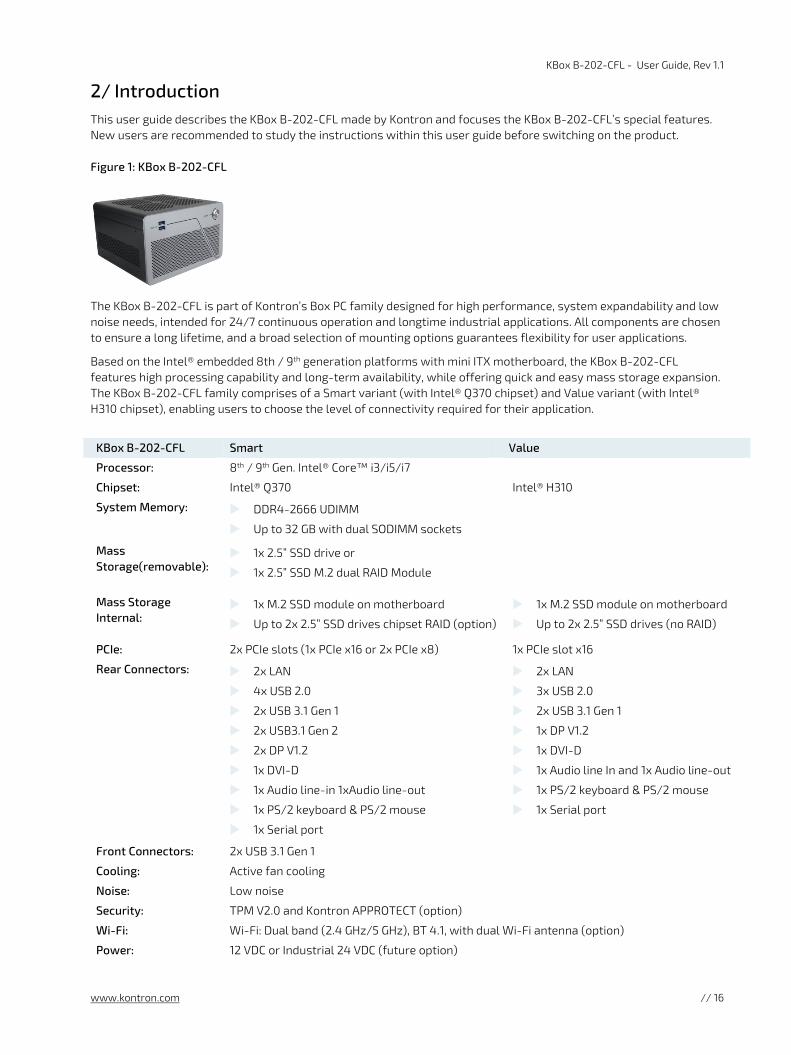
2/ Introduction This user guide describes the KBox B-202-CFL made by Kontron and focuses the KBox B-202-CFL’s special features. New users are recommended to study the instructions within this user guide before switching on the product.
Figure 1: KBox B-202-CFL
The KBox B-202-CFL is part of Kontron’s Box PC family designed for high performance, system expandability and low noise needs, intended for 24/7 continuous operation and longtime industrial applications. All components are chosen to ensure a long lifetime, and a broad selection of mounting options guarantees flexibility for user applications.
Based on the Intel® embedded 8th / 9th generation platforms with mini ITX motherboard, the KBox B-202-CFL features high processing capability and long-term availability, while offering quick and easy mass storage expansion. The KBox B-202-CFL family comprises of a Smart variant (with Intel® Q370 chipset) and Value variant (with Intel® H310 chipset), enabling users to choose the level of connectivity required for their application.
KBox B-202-CFL Smart Value
Processor: 8th / 9th Gen. Intel® Core™ i3/i5/i7
Chipset: Intel® Q370 Intel® H310
System Memory: DDR4-2666 UDIMM
Up to 32 GB with dual SODIMM sockets
Mass Storage(removable):
1x 2.5” SSD drive or
1x 2.5” SSD M.2 dual RAID Module
Mass Storage Internal:
1x M.2 SSD module on motherboard
Up to 2x 2.5” SSD drives chipset RAID (option)
1x M.2 SSD module on motherboard
Up to 2x 2.5” SSD drives (no RAID)
PCIe: 2x PCIe slots (1x PCIe x16 or 2x PCIe x8) 1x PCIe slot x16
Rear Connectors: 2x LAN
4x USB 2.0
2x USB 3.1 Gen 1
2x USB3.1 Gen 2
2x DP V1.2
1x DVI-D
1x Audio line-in 1xAudio line-out
1x PS/2 keyboard & PS/2 mouse
1x Serial port
2x LAN
3x USB 2.0
2x USB 3.1 Gen 1
1x DP V1.2
1x DVI-D
1x Audio line In and 1x Audio line-out
1x PS/2 keyboard & PS/2 mouse
1x Serial port
Front Connectors: 2x USB 3.1 Gen 1
Cooling: Active fan cooling
Noise: Low noise
Security: TPM V2.0 and Kontron APPROTECT (option)
Wi-Fi: Wi-Fi: Dual band (2.4 GHz/5 GHz), BT 4.1, with dual Wi-Fi antenna (option)
Power: 12 VDC or Industrial 24 VDC (future option)

KBox B-202-CFL - User Guide, Rev 1.1
www.kontron.com // 17
3/ Scope of Delivery Check that your delivery is complete, and contains the items listed in Table 1: Scope of Delivery. If you discover damaged or missing items, contact your dealer.
Table 1: Scope of Delivery
Part Qty. Part Description
KBox B-202-CFL 1 High performance PC box:
Smart variant with D3633-S mITX motherboard & Intel® Q370 chipset or Value variant with D3634-S mITX motherboard & Intel® H310 chipset
AC power supply 1 External AC/DC Power Supply (PSU) 100 VAC to 240 VAC
AC power cable 1 Power cable to mains power socket for the region
Chassis feet 4 Self-adhesive chassis feet
Wi-Fi Antenna 2 Wi-Fi antenna (screw on and hinged)
Safety instructions 1 Safety Instructions for IT equipment
Only connect the KBox B-202-CFLto the supplied external AC/DC power supply chosen to
meet the products electrical specification, power consumption, power protection requirements and comply with the safety standards as stipulated by IEC 62368-1.
Table 2: Accessories
Part Qty. Part Description
Mounting Brackets 2 Mounting brackets that attach to the sides for wall mounting
Screw (M3x6) 4 Counter sink screws for mounting brackets or vertical stand
3.1. Packaging
The KBox B-202-CFL is packaged together with all standard parts listed in Table 1: Scope of Delivery, in a product specific cardboard package designed to provide adequate protection and absorb shock.
3.2. Type Label and Product Identification
The type label contains product information such as Model, Power Rating, Product Number (P/N) and Serial Number (S/N). The Product Number (P/N) indicates the product variant; where 2-A0P8-xxxx is the KBox B-202-CFL Smart and 2-A0P7-xxxx the KBox B-202-CFL Value.
Figure 2: Type Labels
1 KBox B-202-CFL Smart 2 KBox B-202-CFL Value
1 2

KBox B-202-CFL - User Guide, Rev 1.1
www.kontron.com // 18
4/ Product Overview Before working with the KBox B-202-CFL, Kontron recommends that users take a few minutes to learn about the various parts of the product.
The KBox B-202-CFL is a high performance PC Box with 8th / 9th generation Intel® Core™ platforms, a mini ITX motherboard and extensive interfaces on the rear panel. System expansion is achieved using an internal M.2 socket, an internal full- sized mPCIe socket and two external PCIe slots. Flexible mass storage expansion supports the setup of two separate RAID arrays using a removable 2.5” SSD dual M.2 RAID module with two on-modules M.2 SSDs and/or two internal 2.5” SSDs.
All product variants are available in a robust metal chassis that guarantees flexibility in multiple user applications.
Figure 3: KBox B-202-CFL Overview

KBox B-202-CFL - User Guide, Rev 1.1
www.kontron.com // 19
4.1. Front Side View
The front panel contains a power-on button, two USB 3.1 ports, and ventilation holes for air-output.
Figure 4: Front Panel
1 2x USB 3.1 Gen 1
2 Ventilation holes (air-output)
3 Power-on button with power LED
4.1.1. Front Connectors and Buttons
4.1.1.1. Power-On Button
The power-on button switches on/off the KBox B-202-CFL. The power-on button includes an integrated power LED that lights up blue to indicate the powered on state. Pressing the power-on button for longer than four seconds initiates a forced system shutdown, before switching off the power.
Performing a forced shut down can lead to loss of data or other undesirable effects!
4.1.1.2. USB 3.1 Gen 1 Port
The two front panel USB 3.1 Gen 1 ports are USB 2.0 backward compatible allowing for the connection of both USB 3.0 or USB 2.0 devices. Further USB ports are available on the rear panel, see Chapter: 4.2: Rear Side.
For the USB 3.1 pin assignment, see Chapter 11.2: USB 3.1 Gen 1 Port & USB 3.1 Gen 2 Pin Assignment.
3 2 1
KBox B-202-CFL - User Guide, Rev 1.1
www.kontron.com // 20
4.2. Rear Side Views
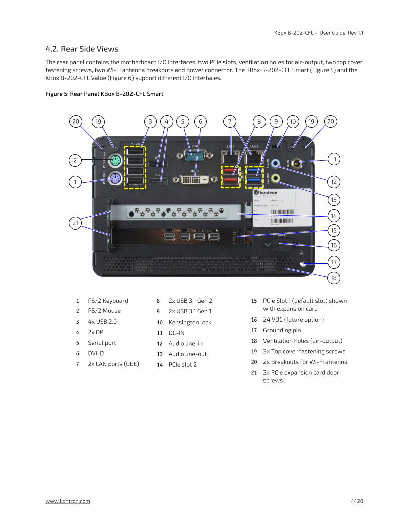
The rear panel contains the motherboard I/O interfaces, two PCIe slots, ventilation holes for air-output, two top cover fastening screws, two Wi-Fi antenna breakouts and power connector. The KBox B-202-CFL Smart (Figure 5) and the KBox B-202-CFL Value (Figure 6) support different I/O interfaces.
Figure 5: Rear Panel KBox B-202-CFL Smart
1 PS/2 Keyboard
2 PS/2 Mouse
3 4x USB 2.0
4 2x DP
5 Serial port
6 DVI-D
7 2x LAN ports (GbE)
8 2x USB 3.1 Gen 2
9 2x USB 3.1 Gen 1
10 Kensington lock
11 DC-IN
12 Audio line-in
13 Audio line-out
14 PCIe slot 2
15 PCIe Slot 1 (default slot) shown with expansion card
16 24 VDC (future option)
17 Grounding pin
18 Ventilation holes (air-output)
19 2x Top cover fastening screws
20 2x Breakouts for Wi-Fi antenna
21 2x PCIe expansion card door screws
2
1
3 5 6
13
16
14
17
18
20 9 7 19
21
4 8
12
11
19 20 10
15

KBox B-202-CFL - User Guide, Rev 1.1
www.kontron.com // 21
Figure 6: Rear Panal KBox B-202-CFL Value
1 PS/2 Keyboard
2 PS/2 Mouse
3 USB 2.0
4 DP
5 Serial port
6 DVI-D
7 2x LAN ports (GbE)
8 2x USB 2.0
9 2 x USB 3.1 Gen 1
10 Kensington lock
11 DC-IN
12 Audio line-in
13 Audio Line-out
14 PCIe slot 2
15 PCIe Slot 1 (Default slot) shown with expansion card
16 24 VDC (future option)
17 Grounding pin
18 Ventilation holes (air-output)
19 2x Top cover screw
20 2x Breakouts for Wi-Fi antenna
21 2x PCIe expansion card door screws
4.2.1. Rear Panel Connectors
4.2.1.1. PS/2 Keyboard Connector
The standard 6-pin mini-DIN PS/2 purple connector enables the connection of a keyboard.
For the pin assignment, see Chapter 11.7: PS/2 Keyboard Connector Pin Assignment.
4.2.1.2. PS/2 Mouse Connector
The standard 6-pin mini-DIN PS/2 green connector enables the connection of a mouse.
For the pin assignment, see Chapter 11.8: PS/2 Mouse Connector Pin Assignment.
1
2
20 19 4 6 5 8 7 9 19 20
11
12
13
16
17
18
21
10 3
14
15

KBox B-202-CFL - User Guide, Rev 1.1
www.kontron.com // 22
4.2.1.3. USB 2.0 Ports
The USB 2.0 ports enable the connection of USB 2.0 devices only. The available USB 3.1 ports are USB 2.0 backward compatible.
For the pin assignment, see Chapter 11.3: USB 2.0 Port Pin Assignment.
4.2.1.4. Display Port (DP)
The Display Port enables the connection of digital displays directly or with an adapter. The DP V1.2 port(s) are Dual mode/ Display Port ++ compatible and depending on the required resolution can support the following maximum number of displays:
Display Resolution (60 frame/sec refresh rate) Number of Displays (Max.)
1680 x 1050 (WSXGA) 5
1920 x 1080 (1080p) or 1920 x 1200 4
2560 x 1600 (WQXGA) 2
3840 x 2160 (Ultra HD, 4K or 4096 x 2160 (4K x 2K) 1
The KBox B 202-CFL Smart supports two DP V 1.2 ports and the KBox B 202-CFL Value supports one DP V 1.2 port
KBox B-202-CFL Smart -supports up to three displays(2x DP+1x DVI-D)
KBox B-202-CFL Value -supports up to two displays (1x DP+1x DVI-D)
Using an adapter to convert a DP signal to DVI or HDMI may cause disturbance.
For the pin assignment, see Chapter 11.5: Display Port (DP) V1.2 Connector Pin Assignment.
4.2.1.5. DVI-D Connector
The DVI-D connector enables the connection of a digital display directly or with an adapter.
DVI DVI-D (single link only)
Resolution 1920x1200 @ 60 Hz
Adapters DVI to HDMI or DVI to VGA
KBox B-202-CFL Smart -supports up to three displays (2x DP+1x DVI-D)
KBox B-202-CFL Value -supports up to two displays (1x DP+1x DVI-D)
Using an adapter to convert DVI to HDMI or DVI to VGA adapters may cause disturbance.
For the pin assignment, see Chapter 11.6: DVI-D Connector Pin Assignment.

KBox B-202-CFL - User Guide, Rev 1.1
www.kontron.com // 23
4.2.1.6. Serial Port (COM)
The serial port 9-pin D_SUB connector enables the connection of a RS232 serial device.
For the pin assignment, see Chapter 11.10: Serial Port Connector Pin Assignment.
4.2.1.7. LAN Ports
The LAN ports support Gigabit Ethernet (10/100/1000 Mb/s), based on the Intel® i219LM & i210AT chips. The two RJ45 LAN connectors include two status LEDs indicating speed and link activity.
Technical Specification Intel® i219M Intel® i210AT
Single port
1 GbE date rate per port
System interface type Proprietary
Network Controller Sideband Interface (NC-SI)
Support for jumbo frames
IEEE 1588
1000Base-T supported interface
For the pin assignment, see Chapter 11.4: LAN Connector Pin Assignment.
4.2.1.8. USB 3.1 Gen 2 Ports
The USB 3.1 Gen 2 ports are backward compatible enabling the connection of USB 3.0 or USB 2.0 devices. Kontron recommends the use of USB 3.1 Gen 2 compliant devices and cables only. The use of devices and cables that violate the USB 3.1 Gen 2 specification may cause non-recognition of the device or read/write errors.
To enhance USB compatibility, in the BIOS setup Advanced>USB Configuration>USB 3.1 Gen 2 Speed, reduce the speed from 10 Gbits/s to 5 Gbits/s.
USB 3.1 Gen 2 is supported only by the KBox B-202-CFL-Smart variant.
For the pin assignment, see Chapter 11.2: USB 3.1 Gen 1 Port & USB 3.1 Gen 2 Pin Assignment.
4.2.1.9. USB 3.1 Gen 1 Ports
The USB 3.1 Gen 1 ports are backwards compatible enabling the connection of USB 3.0 or USB 2.0 compatible devices.
For the pin assignment, see Chapter 11.2: USB 3.1 Gen 1 Port & USB 3.1 Gen 2 Pin Assignment.
4.2.1.10. Audio Connectors ( Line-IN, Line-OUT)
The two audio connectors audio Line-in (blue jack) and audio Line-out (green jack) enable the connection of High Definition (HD) devices. Legacy audio is not supported.
For the pin assignment, see Chapter 11.9: Audio Line-out and Audio Line-in Connector Pin Assignment.

KBox B-202-CFL - User Guide, Rev 1.1
www.kontron.com // 24
4.2.1.11. DC-IN Connector
The 12 VDC Power Jack connects directly to the supplied external AC/DC Power Supply.
For more power specification information, see Chapter 10.6: Power Specification.
Only connect the KBox B-202-CFLto the supplied external AC/DC power supply chosen to
meet the products electrical specification, power consumption, power protection requirements and comply with the safety standards as stipulated by IEC 62368-1.
4.2.1.12. Wi-Fi Antenna Connectors (option)
The Wi-Fi Bluetooth option uses the two breakouts (Figure 5 and Figure 6, pos. 20) for factory installed Wi-Fi antenna connectors and populates the internal mPCIe socket on the motherboard with a mPCIe Wi-Fi card supporting the following technical features:
Dual band frequencies ( 2.4 GHz & 5 GHz)
Bluetooth (BT) 4.1+HS
IEEE802.11 ac/abgn Wi-Fi certified
Max speeds 300 Mbps on N & 867 Mbps on AC
The two Wi-Fi antennas included as part of the Wi-Fi option’s scope of delivery, screw directly on to the Wi-Fi antenna connectors.

KBox B-202-CFL - User Guide, Rev 1.1
www.kontron.com // 25
4.3. Left and Right Side Views
The right and left sides contain ventilation holes for air-output. The ventilation holes on the right side are contained within a removable PCIe expansion card door.
The two pairs of threaded screw holes available on both sides (Figure 7, pos. 3) lower and (Figure 7, pos. 4) upper, are used to attach wall mount brackets, see Chapter 8.2: Mounting Brackets (option).
Figure 7: Left Side and Right Side
1 Removable PCIe expansion card door with ventilation holes for air-output
2 PCIe expansion card door screws
3 Lower pair of threaded screw holes for wall mount brackets
4 Upper pair of threaded screw holes for wall mount brackets
5 Position of PCIe expansion card slot 2 6 Position of PCIe expansion card slot 1 7 PCIe card’s front pin
1
3
4
3
4
6
5
7
2

KBox B-202-CFL - User Guide, Rev 1.1
www.kontron.com // 26
4.4. Top Cover and Bottom Side Views
The top cover consisting of a metal plate with ventilation holes for air-intake and a separate metal plate underneath with a circular opening above the internal fan.
Figure 8: Top View
1 Ventilation holes (air-intake)
2 Circular opening on metal plate
The bottom side contains an external drive bay with cover that opens or closes using a single screw (Figure 9, pos. 3).
Figure 9: Bottom View
1 2.5” SSD drive bay cover
2 4 x Threaded holes (extra mounting option)
3 Drive bay cover screw 4 4x Rubber feet
3
1
1
2
2
4
4
4
4

KBox B-202-CFL - User Guide, Rev 1.1
www.kontron.com // 27
5/ System Extension Kontron recommends expanding the KBox B-202-CFL, before installing the product in the end environment.
5.1. System Storage and Expansion Card Combinations
The supported drives and expansion cards depend on the technical specification of the motherboard variants (Smart or Value), and space limitation on the motherboard and within the chassis.
Figure 10: System Expansion Options
1x 2.5" SSDRAID
(Internal)
1x 2.5" SSDRAID
(Internal)
2x PCIe Slots
or
1x PCIe slot
1x 2.5" SSD drive (removable)
or 2.5" SSD RAID Module with dual M.2 SSD (removable)
mPCIe socket
M.2 socket
1 2x PCIE slots (x16 or x8+x8) (Smart only ) or 1x PCIE slot (x16) (Smart and Value)
2 1x 2.5” SSD drive or 1x 2.5” SSD M.2 dual RAID module
3 Up to two factory-installed 2.5” SSD drives in an internal cage with Chipset RAID (Only Smart variant supports Chipset RAID). When installed the usable PCIe slots are limited to one slot.
4 1x mPCIe card socket (on-board) 5 1x M.2 SSD module socket (on-board)
3
2
5
4
1

KBox B-202-CFL - User Guide, Rev 1.1
www.kontron.com // 28
Due to limited motherboard space, not every mPCIe expansion card (Figure 10, pos. 4) and M.2 module (Figure 10, pos. 5) combination is possible. The supported M.2 SSD module and mPCIe expansion card motherboard combinations are shown in Table 3.
Table 3: M.2 SSD Module and mPCIe Expansion Card Combinations
Expansion Device (motherboard) Option 1 Option 2 Option 3
1x M.2 2280 module
1x M.2 2242 module
1x mPCIe (half-size) expansion card
1x mPCIe (full-size) expansion card
Due to limited internal space within the chassis, not every storage and expansion card combination is possible. The supported storage and expansion card combinations are shown in Table 4.
Table 4: Storage and Expansion Card Combinations
Expansion Device ( System) Option 1 Option 2 Option 3 Option 4
1x 2.5” SSD drive (removable)
Up to 2x PCIe slots (1x 16) or (2x 8) [1] [2] 1x 2.5” SSD dual M.2 RAID module (removable)
1 x PCIe slot (1x 16) or (1x 8) [2]
Up to 2x internal 2.5” SSD drive(s) with Chipset RAID [2]
[1] KBox B-202-CFL Value supports only one PCIe x16 slot.
[2] The up to two internal 2.5” SSD drive(s) limits the number of usable PCIe slots to one.

KBox B-202-CFL - User Guide, Rev 1.1
www.kontron.com // 29
5.2. Mass Storage Devices
5.2.1. 2.5” SSD Drive
The external drive bay supports one 2.5” SSD drive using the SATA III, 6 Gb/s interface.
Due to space restrictions, only one removable device may be installed in the external drive bay 2.5”SSD drive or 2.5” SSD dual RAID Module.
5.2.2. 2.5” SSD dual M.2 RAID Module
The external drive bay supports one 2.5” SSD dual M.2 RAID module with up to two M.2 SSD modules using the SATA III, 6 Gb/s interface, and supporting either RAID 0 and RAID 1.
Due to space restrictions, only one removable device may be installed in the external drive bay 2.5”SSD drive or 2.5” SSD dual RAID Module.
5.2.3. Internal 2.5” SSD Drives
Up to two internal 2.5” SSD drives with the option to use chipset RAID. The drives are factory installed and not accessible to the user. Due to internal space restrictions, the installation of the internal 2.5” SSD drive(s) limits the number of usable PCIe slots to one slot.
Due to internal space restrictions, the installation of internal 2.5” SSD drive(s) limits the number of usable PCIe slots to one slot.
5.2.4. On-board M.2 SSD Module
The on-board M.2 Key M socket supports one 2280 or 2242 M.2 SSD module, using the following interfaces:
PCIe (Gen 3) @ 4 lanes (Smart variants)
PCIe (Gen 2) @ 2 lanes (Value variants)
No support for SATA based M.2 modules on the motherboard.
HDD Password support for disk drives and M.2 SSD module access protection.
Due to on-board space restrictions, not every M.2 module/mPCIe card combination is possible. Before installing a M.2 module users must consider whether a mPCIe card populates the neighboring mPCIe socket. If a mPCIe card populates the neighboring mPCIe socket, no 2280 M.2 SSD module may be installed. Whereas, if a half-size or full size mPCIe card populates the neighboring socket, a 2242 M.2 SSD module may be installed. For the allowed M.2 SSD module/mPCIe card combinations, see Table 3: M.2 SSD Module and mPCIe Expansion Card Combinations.
For the KBox B-202-CFL Wi-Fi option the mPCIe socket is populated with a half-size mPCIe Wi-Fi card and the M.2 socket is restricted to a 2242 M.2 SSD module.
Due to limited motherboard space, not every mPCIe card and M.2 module combination is possible.

KBox B-202-CFL - User Guide, Rev 1.1
www.kontron.com // 30
5.3. Expansion Cards
When adding PCIe expansion cards ensure that the product’s total power consumption with PCIe cards does not exceed the supplied power supply’s rating of 150 W, see Chapter 10.6.1: Power Consumption.
The total power consumption with PCIe cards must not exceed the PSU’s rating of 150 W.
5.3.1. PCIe Expansion Cards
The numbers of usable PCIe (full-height, half-length) expansion cards slots depends on the KBox B-202-CFL variant (Smart or Value), where the Smart variant supports one PCIe x16 or two PCIE x8 expansion card(s) and the Value variant supports one PCIe x16 expansion card only. The supported PCIe expansion card types are:
One PCIe x16 Gen 3
Two PCIe x8 Gen 3 (Smart variant only)
Due to internal space restrictions, the installation of internal 2.5” SSD drive(s) limits the number of usable PCIe slots to one slot.
The KBox B-202-CFL Value variant supports only one PCIe x16 expansion card.
Due to internal space restrictions, the installation of internal 2.5” SSD drive(s) limits the number of usable PCIe slots to one slot.
5.3.2. On-board mPCIE Expansion Card
The on-board mPCIe socket supports one mPCIe x1 (full-size or half-size) mPCIe expansion card using the following interface types:
PCIe Gen 3 interface (Smart variant)
PCIe Gen 2 interface (Value variant)
Due to on-board space restrictions, not every M.2 module/mPCIe card combination is possible. Before installing a mPCIe expansion card (full-size or half-size), users must consider the form factor of the M.2 module’s that populates the neighboring M.2 socket. No mPCIe card may be installed when a 2280 M.2 SSD modules populates the neighboring M.2 socket. Whereas, both half-size and full-size mPCIe cards may be installed when a 2242 M.2 SSD modules populates the neighboring M.2 socket. For the allowed M.2 SSD module/mPCIe card combinations, see Table 3: M.2 SSD Module and mPCIe Expansion Card Combinations.
For the KBox B-202-CFL Wi-Fi option the mPCIe socket is populated with a half-size mPCIe Wi-Fi card and the M.2 socket use is restricted to a 2242 M.2 SSD module.
Due to limited motherboard space, not every mPCIe card and M.2 module combination is possible.

KBox B-202-CFL - User Guide, Rev 1.1
www.kontron.com // 31
6/ Accessing Components This chapter contains important information that users must read before opening the KBox B-202-CFL to access internal components. Additionally, read and observe the General Safety Instructions for IT-Equipment contained in this user guide. . Kontron recommends expanding the KBox B-202-CFL, before installing the product in the end environment.
Before opening the product by removing the top cover, make sure that the product is
switched off using the power-on button and disconnected from the mains power supply.
Disconnect all connected peripheral devices. Observe the General Safety Instructions for IT Equipment within this user guide.
Handling and operation of the product is permitted only for trained personnel aware of the
associated dangers, within a work place that is access controlled and fulfills all necessary technical and environmental requirements.
Follow the electrostatic discharge (ESD) precautions for components that are sensitive to ESD and use a clean, flat and ESD-safe surface when handling the product. Failure to observe this warning notice may result in damage to the product or/and internal components.
Pay attention to the manufacturer’s instructions before installing or removing third party components.
6.1. Removing and Installing the Top Cover
Before removing the top cover, to access internal components, observe the safety instructions within this chapter.
Operate in the closed condition only
It is only ensured that users do not have access to internal components during operation when the top cover is properly secured with the two top cover fastening screws.
To remove the top cover, perform the following:
1. Close all applications. Switch off the product properly using the power-on button and disconnect the mains power supply. Disconnect all peripherals.
2. Place the KBox B-202-CFL on a flat, clean and ESD-safe surface.
3. Unlock and remove the Kensington lock if installed (Figure 11, pos. 2).
4. Remove the two top cover screws on the rear panel (Figure 11, pos. 1) and retain the screws for later use.

KBox B-202-CFL - User Guide, Rev 1.1
www.kontron.com // 32
Figure 11: Top Cover Fastening Screws
1 Top cover screws
2 Kensington lock
5. Lift the top cover a few centimeters at the rear of the chassis and then pull the top cover gently away from the front panel to release the top cover from the holding brackets (Figure 12, pos. 1) on the front panel.
Figure 12: Holding Brackets
1 Holding brackets
6. Once released from the holding brackets lift the top cover vertically to avoid damaging the internal fan assembly. Do not side the top cover off the chassis.
Do not slide the top cover off/onto the chassis!
Avoid contact and possible damage between the top cover and the internal fan assembly by lifting the top cover vertically.
To install the top cover, perform the following:
1. Place the KBox B-202-CFL on a flat, clean and ESD-safe surface.
2. Hold the top cover over the main chassis and move downwards until the top cover is almost in the correct position above the main chassis.
Do not slide the top cover off/onto the chassis!
Avoid contact and possible damage between the top cover and the internal fan assembly by moving the top cover vertically downwards.
3. Tilt the front side of the top cover downwards towards the front panel and the push the top cover onto the holding brackets on the front panel (Figure 12, pos. 1), until the top cover is in-line with the front panel.
4. Move the rear side downwards onto the rear panel and secure with the two screws retained previously in step 4.
2
1
1

KBox B-202-CFL - User Guide, Rev 1.1
www.kontron.com // 33
6.1.1. Installing and Removing an On-board mPCIe Expansion Card
To install an mPCIe card on the motherboard, perform the following:
1. Remove the top cover as described in Chapter 6.1: Removing and Installing the Top Cover.
2. Locate the mPCIe card socket and the corresponding nut on the motherboard.
3. Insert and push the mPCIe card into the socket gently, at a slight angle, until the fixing hole on the mPCIe card aligns with the corresponding motherboard’s nut.
4. Secure the mPCIe card by pressing down on the free end and carefully fixing with a screw to the corresponding nut on the motherboard, until flat with the motherboard.
Do not use force when fastening the mounting screw. Too much force may damage the
motherboard’s nut. Recommended torque for mPCIe screw is 0.2 Nm.
5. Close the Chassis as described in Chapter 6.1: Removing and Installing the Top Cover.
To remove a mPCIe card, perform the following:
1. Open the chassis as described in Chapter 6.1: Removing and Installing the Top Cover.
2. Locate the installed mPCIe card and remove the fixing screw. The mPCIe card springs up at the free end.
3. Pull the mPCIe card out of the socket carefully.
4. Close the chassis as described in Chapter 6.1: Removing and Installing the Top Cover.
6.1.2. Installing and Removing an On-board M.2 SSD Module
After installing or removing a M.2 SSD module, memory partitioning maybe different.
To install an M.2 module on the motherboard, perform the following:
1. Open the chassis as described in Chapter 6.1: Removing and Installing the Top Cover.
2. Locate the M.2 socket and the corresponding nut on the motherboard.
3. Insert and push the M.2 module into the socket gently at a slight angle until the fixing hole on the M.2 module aligns with the corresponding motherboard’s nut.
4. Secure the M.2 SSD module by pressing down on the free end, and carefully fixing with a screw to the corresponding nut on the motherboard, until flat with the motherboard.
Do not use force when fastening the mounting screw. Too much force may damage the
motherboard nut. Recommended torque for M.2 screw is 0.2 Nm.
5. Close the Chassis as described in Chapter 6.1: Removing and Installing the Top Cover.
To remove an M.2 SSD module, perform the following:
1. Open the chassis as described in Chapter 6.1: Removing and Installing the Top Cover.
2. Locate the installed M.2 SSD module and remove the fixing screw. The M.2 module springs up at the free end.

KBox B-202-CFL - User Guide, Rev 1.1
www.kontron.com // 34
3. Pull the M.2 SSD module out of the M.2 socket carefully.
4. Close the Chassis as described in Chapter 6.1: Removing and Installing the Top Cover.
6.2. Installing and Removing a PCIe Card
Before opening the PCIe expansion card door, observe the safety instructions within this chapter.
Operate only when the PCIe expansion card door is closed and secured, to ensure that users
do not have access to internal components during operation.
To install a PCIe expansion card, perform the following:
1. Close all applications shut down the product properly using the power-on button and disconnect the mains power supply. Disconnect all peripherals.
2. Place the chassis on a flat, clean and ESD-safe surface with the left side facing upwards.
3. Loosen the two screws holding the PCIe expansion card door (Figure 13, Pos. 1). Retain the screw for later use.
Figure 13: PCIe Expansion Card Screws
1 2x PCIe expansion card door screws
4. Move the PCI expansion card door outwards at the free end and slide towards the rear of the chassis to release the door’s front holding plate (Figure 13, pos. 1).
5. To install a PCIe expansion card, in an empty PCIe slot remove the slot bracket by first releasing the slot bracket from the front pin (Figure 15, pos. 1 or 2) and then sliding the slot bracket’s front end out of the holding latch (Figure 16, pos. 1).
Figure 14: Removing PCIe Expansion Card Door
1 PCIe expansion card door
2 PCIe slot 2 (shown empty)
3 PCIe slot 1 (default slots shown populated)
1
1 2
3

KBox B-202-CFL - User Guide, Rev 1.1
www.kontron.com // 35
Figure 15: PCIe Slot Front Pin
1 Front pin slot 2
2 Front pin slot 1
Figure 16: PCIe Expansion Slot Holding Latch
1 Holding latch for the PCIe card’s bracket tab
6. Aline the expansion card with the corresponding internal PCIe slot. Push the expansion card carefully into the PCIe connector, while ensuring the expansion card’s bracket inserts into the holding latch (Figure 16, pos. 1). Position the other end of the expansion card’s bracket on the corresponding front pin (Figure 15, pos. 1 or 2).
Figure 17: PCIe Expansion Card Door
1 Holding plate PCIe expansion card door
2 2x fixing screw holes
7. Secure the PCIe expansion card door by positioning the holding plate (Figure 17, pos. 1) in the inside of the chassis. Push the door until the door’s two screw holes (Figure 17, pos. 2) align with the screw holes on the rear side of the chassis. (Figure 13, pos. 1). Secure the door with the screws retained in step 3.
To remove a PCIe expansion card, perform the following:
1. Close all applications shut down the product properly using the power-on button and disconnect the mains power supply. Disconnect all peripherals.
2. Place the chassis on a flat, clean and ESD-safe surface with the left side facing upwards.
3. Open the PCIe expansion card door by proceeding as described in the previous steps 3 to 4.
4. Remove the expansion card by releasing the expansion card’s bracket from the front pin (Figure 15, pos. 1 or 2) and sliding the expansion card’s front end out of the holding latch (Figure 16, pos. 1). Continue to pull the expansion card outward to remove the expansion card from the PCIe slot.
5. Place the PCIe expansion card on an ESD-safe surface.
1
1
2
1
2

KBox B-202-CFL - User Guide, Rev 1.1
www.kontron.com // 36
6. Insert an empty slot bracket if the PCIe slot is to remain unused, else proceed as described in the previous steps 5 to 6 to install a PCIe expansion card.
7. Secure the PCIe expansion card door as described in the previous step 7.
6.3. Opening and Closing the Drive Bay Cover
Before opening the drive bay cover, observe the safety instructions at the start of this chapter.
To open the drive bay cover, perform the following:
1. Close all applications. Shut down the product properly using the power-on button and disconnect the mains power supply. Disconnect all peripherals.
2. Place the product on a flat, clean and ESD-safe surface with the bottom side facing upwards.
3. Release the drive bay cover’s screw using a torx (08 x 60) screwdriver (Figure 9, pos. 3).
4. Lift up the drive bay cover a few centimeters to release the internal device from the holding plate on the cover’s rear side (Figure 18, pos. 1).
Figure 18: Drive Bay Cover Rear Side
1 Holding plate
5. Slide the drive bay cover forward, to release the two aligning tabs (Figure 19, pos. 1).
Figure 19: Drive Bay Cover Top Side
1 Aligning Tabs
6. Lift to remove the drive bay cover from the drive bay.
7. Close the drive bay cover, by proceeding in the reverse order (steps 6 to 3).
To avoid damage, do not use force when closing the drive bay cover.
If the drive bay cover does not close easily, the metal holding plate may not be aligned correctly and pressing down with force may damage the installed 2.5” SSD drive or 2.5” SSD dual RAID Module.
1
1

KBox B-202-CFL - User Guide, Rev 1.1
www.kontron.com // 37
6.3.1. Installing and Removing a 2.5” SSD Drive
Before installing a 2.5” SSD drive, observe the SSD drive manufacturer’s instructions.
To install a 2.5” SSD in the drive bay, perform the following:
1. Close all applications. Shut down the product properly using the power-on button and disconnect the mains power supply. Disconnect all peripherals.
2. Place the product on a flat, clean and ESD-safe surface with the bottom side facing upwards.
3. Open the drive bay cover as described in Chapter 6.3: Opening and Closing the Drive Bay Cover (steps 1 to 6).
4. Position the SSD in the drive bay on the ESD strip (Figure 20, pos. 1) with the SSD’s connector facing the drive bay’s internal SATA connector (Figure 20, pos. 3).
Figure 20: External Drive Bay with 2.5” SSD Drive
1 ESD strip
2 2.5” SSD drive
3 Drive bay SATA connector
5. Align the SSD’s connector with the drive bay’s SATA connector.
6. Press down and gently push the SSD into the SATA connector.
7. Close the drive bay cover as described in Chapter 6.3: Opening and Closing the Drive Bay Cover (steps 7).
After installing or removing a 2.5” SSD, the partitioning of the memory maybe different.
To remove a 2.5” SSD drive from the drive bay, perform the following:
1. Close all applications. Shut down the product properly using the power-on button and disconnect the mains power supply. Disconnect all peripherals.
2. Place the product on a flat, clean and ESD-safe surface with the bottom side facing upwards.
3. Open the drive bay cover as described in Chapter 6.3: Opening and Closing the Drive Bay Cover (steps 1 to 6).
4. Pull the 2.5” SSD out of drive bay’s SATA connector gently.
5. Place the 2.5” SSD on an ESD-safe surface.
6. Close the drive bay cover as described in Chapter 6.3: Opening and Closing the Drive Bay Cover (steps 7).
After installing or removing a 2.5” SSD, the partitioning of the memory maybe different.
1
2
3

KBox B-202-CFL - User Guide, Rev 1.1
www.kontron.com // 38
6.3.2. Installing and Configuring the 2.5” SSD dual M.2 RAID Module
The 2.5” SSD dual M.2 RAID module is factory installed and hardware configured as a RAID 1 array (default). Do not press the RAID module’s reset switch (Figure 21, pos. 3) without considering if a backup of the data is required. Pressing the reset switch reconfigures the RAID array and the data on both M.2 SSDs will be lost.
If a faulty M.2 SSD is replaced, do not press the reset switch. When the 2.5” SSD dual M.2 RAID module is powered on again, the previous configuration will be copied automatically to the new M.2 SSD, see Chapter 6.3.3: Replacing a M.2 SSD Module.
Do not reset the RAID module without considering if a backup of the data is required.
Pressing the reset switch configures the RAID array and data on both drives will be lost.
After replacing one of the M.2 SSD modules on the RAID module, do not reset the RAID module! When the RAID module is powered on for the first time, the previous RAID configuration will be copied to the new M.2 SSD module automatically.
Figure 21: 2.5” SSD dual RAID M.2 Module
1 Jumper (J1) in position 1
2 Jumper (J2) in position 2
3 Reset switch
4 4x Foam buffer
5 2x screws for M.2 SSD module
6 M.2 socket 1
7 M.2 socket 2
8 M.2 SSD module in socket 2
9 SATA power connector
10 SATA data connector
11 M.2 SSD module in socket 1
To install and configure the 2.5” SSD dual M.2 RAID module, perform the following:
1. Close all applications. Shut down the product properly using the power-on button and disconnect the mains power supply. Disconnect all peripherals.
2. Place the product on a flat, clean and ESD-safe surface with the bottom side facing upwards.
3. Open the external drive bay, see Chapter 6.3: Opening and Closing the Drive Bay Cover.
4. Place the 2.5” SSD dual M.2 RAID module on an ESD-safe surface.
5. Inserting the M.2 SSD modules at a slight angle gently into the 2.5“ SSD dual M.2 RAID module’s M.2 sockets (Figure 21, pos. 6 and 7). Press down on the free end to align the M.2 SSD module’s screw hole with the 2.5” SSD dual RAID module’s nut and secure each M.2 SSD module with a screw (Figure 21, pos. 5).
2 3 4
5
4
6 7 8 9
11 1 10

KBox B-202-CFL - User Guide, Rev 1.1
www.kontron.com // 39
6. Place self-adhesive form buffers on each of the M.2 SSD modules (Figure 21, pos. 4).
7. If the 2.5” SSD dual M.2 RAID module is already configured with a RAID array, then insert the 2.5” SSD dual M.2 RAID module into the SATA connector in the external drive bay with the two M.2 SSDs modules faces the inside of the drive bay (Figure 22) and then precede to step 10.
Do not reset the RAID module. When the RAID module is powered on, the previous RAID
configuration will be copied to the new M.2 SSD module automatically.
8. If the2.5” SSD dual M.2 RAID module is not configured with a RAID array, first set the jumpers J1 and J2 (Figure 21, pos. 1 and 2) to the position for the required RAID array type, see Table 5.
Table 5: RAID Module Jumper Settings
RAID Array Type J1 Setting J2 Setting
RAID 0 2 2
RAID 1 1 2
9. To configure the 2.5” SSD dual M.2 RAID module, the 2.5” SSD dual M.2 RAID module must receive power on the SATA data and SATA power connectors and the reset button must be pressed for approximately 3 seconds. To perform this, use either (a) the KBox B-202-CFL’s drive bay or (b) an external SATA adapter and SATA source:
a) Insert the 2.5” SSD dual M.2 RAID module into the SATA connector in the external drive bay with the side of the 2.5” SSD dual M.2 RAID module with the two M.2 SSDs modules facing the inside of the drive bay (Figure 22). Switch on the KBox B-202-CFL to power the SATA connectors (power and data). Place a small nonconductive blunt-utensil underneath the 2.5” SSD dual M.2 RAID module where the rest switch (Figure 21, pos. 3) is located and press down gently on the 2.5” SSD dual M.2 RAID module’s free end for approximately 3 seconds or until a click tone confirms the reset. The 2.5” SSD dual M.2 RAID module automatically configures to the RAID array type, set in step 8.
Danger of Fire when positioned top side down
To configure the RAID module for the first time, users may be required to switch on the KBox B 202-CFL while the top cover faces downwards, to enable access to the drive bay when the SATA connectors are power on. Operating the product in this position is a fire hazards, as air-intake ventilation holes are obstructed which causes overheating and internal parts to melt and drip out of the ventilation holes.
After configuring the RAID module, return the product immediately to an allowed orientation!
b) Connect a SATA adapter cable (power and data) to a SATA source. Connect the other end of the adapter cables to the 2.5” SSD dual M.2 RAID module. Switch on the SATA source and press the reset switch (Figure 21, pos. 3) for three seconds or until a click tone confirms the reset. The 2.5” SSD dual M.2 RAID module automatically configures to the RAID array type, set in step 8. Switch off the SATA power source and remove the SATA adapter cable from the 2.5” SSD dual M.2 RAID module. Insert the 2.5” SSD dual M.2 RAID module into the SATA connector in the external drive bay with the side of the 2.5” SSD dual M.2 RAID module with the two M.2 SSDs modules facing the inside of the drive bay (Figure 22).

KBox B-202-CFL - User Guide, Rev 1.1
www.kontron.com // 40
Figure 22: External Drive Bay with 2.5” SSD dual M.2 RAID Module
1 2.5” SSD dual M.2 RAID module with two M.2 SSD modules (shown here bottom side up)
2 SATA connector
10. Close and secure the drive bay cover as described in Chapter 6.3: Opening and Closing the Drive Bay Cover (step 7).
To remove the 2.5” SSD dual M.2 RAID module in the drive bay, perform the following:
1. Close all applications. Shut down the product properly and disconnect the mains power supply. Disconnect all peripherals.
2. Place the product on a flat, clean and ESD-safe surface with the bottom side facing upwards.
3. Open the cover on the bottom side of the product; see Chapter 6.3: Opening and Closing the Drive Bay Cover.
4. Hold the 2.5” SSD dual M.2 RAID module on the sides and gently pull the 2.5” SSD dual M.2 RAID module away from the SATA connectors.
5. Place the 2.5” SSD dual M.2 RAID Module on an ESD-safe surface.
6. Close the drive bay cover, see Chapter 6.3: Opening and Closing the Drive Bay Cover (step 7).
6.3.3. Replacing a M.2 SSD Module
Do not reset the RAID module without considering if a backup of the data is required.
Pressing the reset switch configures the RAID array and data on both drives will be lost.
After replacing one of the M.2 SSD modules on the RAID module, do not reset the RAID module! When powered on for the first time, the previous RAID configuration will be copied to the new M.2 SSD module automatically.
To replace a faulty M.2 SSD module on the 2.5” SSD dual M.2 RAID module, perform the following:
1. Remove the 2.5”SSD dual M.2 RAID module from the KBox B-202-CFL, see Chapter 6.3.2: Installing and Configuring the 2.5” SSD dual M.2 RAID Module.
2. Place the 2.5” SSD dual M.2 RAID module on an ESD safe surface.
3. Locate the faulty M.2 SSD module(s), using the information given in the iRAID notification email such as serial number, see Chapter 13.1: iRAID Utility Software.
1
2

KBox B-202-CFL - User Guide, Rev 1.1
www.kontron.com // 41
4. Remove the fastening screw that secures the faulty M.2 SSD module and retain the screw for later use. The M.2 SSD module flips upwards at a slight angle. Pull the M.2 SSD module gently out of the M.2 socket.
5. Insert a new M.2 SSD module at a slight angle gently into the M.2 socket and press down on the free end to align the M.2 SSD module’s screw hole with the 2.5” SSD dual RAID module’s nut and secure with the screw retained in step 4.
Kontron recommends replacing a faulty drive with a drive of the same capacity and type as the mirrored drive. When different capacity drives are used, the working capacity is only as large as the smallest drive’s capacity.
6. Place a self-adhesive foam buffers on each M.2 SSD module (Figure 21, pos. 4).
7. Insert the 2.5” SSD dual M.2 RAID module, with the two M.2 SSDs modules facing the inside of the external drive bay (Figure 22).
8. Close and secure the drive bay cover.
9. Switch on the KBox B-202-CFL and RAID array configures the new drive automatically.
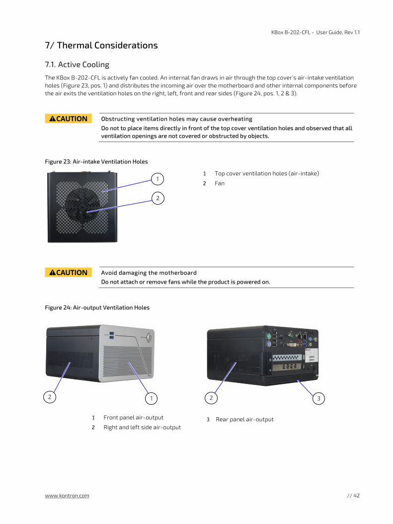
KBox B-202-CFL - User Guide, Rev 1.1
www.kontron.com // 42
7/ Thermal Considerations
7.1. Active Cooling
The KBox B-202-CFL is actively fan cooled. An internal fan draws in air through the top cover’s air-intake ventilation holes (Figure 23, pos. 1) and distributes the incoming air over the motherboard and other internal components before the air exits the ventilation holes on the right, left, front and rear sides (Figure 24, pos. 1, 2 & 3).
Obstructing ventilation holes may cause overheating
Do not to place items directly in front of the top cover ventilation holes and observed that all ventilation openings are not covered or obstructed by objects.
Figure 23: Air-intake Ventilation Holes
1 Top cover ventilation holes (air-intake)
2 Fan
Avoid damaging the motherboard
Do not attach or remove fans while the product is powered on.
Figure 24: Air-output Ventilation Holes
1 Front panel air-output
2 Right and left side air-output 3 Rear panel air-output
1 2 2 3
1
2

KBox B-202-CFL - User Guide, Rev 1.1
www.kontron.com // 43
7.2. Mount Orientation
When mounted underneath a desktop, on the wall, or in a control cabinet, the permitted mounting orientations are horizontal (top side facing upward) and vertical (all possible mount orientations).
Do not mount the KBox B-202-CFL with the top cover facing downwards. When the top cover faces downwards not enough air is taken in to cool the processor adequately; causing overheating and/or melting. Hence, this creates a possible fire hazard due to hot substances exiting through the top cover’s ventilation holes.
Danger of Fire
Mounting the KBox B 202-CFL with the top cover facing downward, may cause overheating or melting and hence may causing a fire hazard or personal injury. To avoid risk of fire and personal injury, observe the following:
Do not mount with the top cover facing downward
Only use the permitted mount orientations:
Horizontally (with top cover facing upwards) Vertically (all possible mount orientations)
7.3. Minimum Clearance (Keep Out Area)
To provide maximum airflow through and around the chassis, a minimum distances to surrounding parts must be observed. Before mounting the product, consider the keep out areas required for the mounting method and the orientation to be used.
Leave sufficient clearance (keep out area) to prevent the product from overheating!
To ensure proper operation use the specified recommended keep out areas of :
Top cover: 10 mm (0.394")
Left and right sides: 10 mm (0.394")
Front and rear panel: 10 mm (0.394")
Bottom side: (no restriction)
7.4. Third Party Components
When expanding with third party components such as mPCIe expansion cards, PCIe expansion cards, M.2 SSD modules, 2.5” SSD drives and 2.5” SSD dual M.2 RAID module, the air temperature inside the product is higher than the ambient temperature. An approximate internal temperature rise is given and should be taken into consideration.

KBox B-202-CFL - User Guide, Rev 1.1
www.kontron.com // 44
8/ Installation Instructions The KBox B-202-CFL can be operated horizontally (top side facing upward) and vertical in all possible mount orientations. Before Installing the KBox B-202-CFL, observe the following instructions.
Danger of Fire
Mounting the KBox B 202-CFL with the top cover facing downward, may cause overheating or melting and hence may causing a fire hazard or personal injury. To avoid risk of fire and personal injury, observe the following:
Do not mount with the top cover facing downward
Only use the permitted mount orientations:
Horizontally (with top cover facing upwards) Vertically (all possible mount orientations)
Handling and operation of the product is permitted only for trained personnel aware of the
associated dangers, within a work place that is access controlled and fulfills all necessary technical and environmental requirements.
Prior to any installation work ensure that there are no live wires on the installation site and
follow the local/national regulations for grounding. The voltage feeds must not be overloaded. Adjust the cabling and the overcurrent protection to correspond with the electrical figures indicated on the type label located on the bottom side of the product. Kontron recommends that the last cable to be attached is the power cable.
Leave sufficient clearance (keep out area) to prevent the product from overheating!
To ensure proper operation use the specified recommended keep out areas of :
Top cover: 10 mm (0.394")
Left and Right sides: 10 mm (0.394")
Front and Rear panel: 10 mm (0.394")
Bottom side: (no restriction)
Ensure the product’s weight can be supported by mounting on a flat, solid surface using
suitable screws.
Ensure sufficient clearance for user to:
Connect cables on the rear I/O panel
Access power-on button on the front panel
Install PCIe cards on the right side (clearance 110 mm)
Install Wi-Fi antennas on rear panel (clearance 45 mm and 130 mm from Wi-Fi hinge)

KBox B-202-CFL - User Guide, Rev 1.1
www.kontron.com // 45
8.1. Chassis Feet
To use on a desktop, install the supplied four self-adhesive rubber chassis feet as follows:
1. Ensure the bottom surface is clean and free from dust and dirt.
2. Remove the self-adhesive cover from the back of each of the rubber chassis feet and carefully press onto the bottom side (Figure 25, pos. 1).
Figure 25: Position of Chassis Feet
1 Position of four rubber feet
To improve stability, positioning the chassis feet between mounting hole and outside edge of the corners.
8.1.1. Chassis Feet Mount (option)
The KBox B-202-CFL with chassis feet can be operated in the upwards horizontal position only.
Figure 26: Chassis Feet Mount Option
Danger of Fire
Mounting the KBox B 202-CFL with the top cover facing downward, may cause overheating or melting and hence may causing a fire hazard or personal injury. To avoid risk of fire and personal injury, observe the following:
Do not mount with the top cover facing downward
Only use the permitted mount orientations:
Horizontally (with top cover facing upwards) Vertically (all possible mount orientations)
1

KBox B-202-CFL - User Guide, Rev 1.1
www.kontron.com // 46
8.2. Mounting Brackets (option)
To mount on a wall (vertically or horizontally) or fix on a desktop (underneath or topside) use mounting brackets. The mounting brackets sets are available as an accessory, see Table 2: Accessories.
Figure 27: Mounting Bracket
1 Mounting holes (10 mm keep out area)
2 Mounting holes (no keep out area) 3 Key mounting holes for mount surface
Each mounting bracket contains two sets of mounting holes. Which set of holes is used depends on whether a keep out area is required for ventilation.
Top cover ventilation holes face the mount surface:
10 mm keep out area is required between top cover and mount surface. Use only mounting holes shown in Figure 27, pos. 1
Bottom side faces the mounting surface:
No keep out area is required between bottom cove and mount surface Use the mounting holes shown in Figure 27, pos. 2.
Obstructing the ventilation holes may cause overheating.
Do not to place items directly in front of the top cover ventilation holes and observed that all ventilation openings are not covered or obstructed by objects.
Leave sufficient clearance (keep out area) to prevent the device from overheating!
To ensure proper operation, use the specified recommended keep out areas of:
Top cover: 10 mm (0.394")
left and right side: 10 mm (0.394")
Front and rear panel: 10 mm (0.394")
Bottom side ( no keep out area)
To mount the KBox B-202-CFL using mounting brackets, perform the following:
1. Consider which set of mounting brackets holes is required for the mounting option:
Top cover facing mounting surface, use the mounting holes Figure 27, pos. 1 Bottom side facing mounting surface, use the mounting holes Figure 27, pos. 2
2. Locate the lower and upper sets of mounting holes on the right side and left side of the chassis::
Lower set enables mounting options Figure 30 and Figure 32 Upper set enables mounting options Figure 31 and Figure 33
3. Align the required mounting bracket hole (step 1) with require mounting holes (step 2) to mount correctly.
1
2
3

KBox B-202-CFL - User Guide, Rev 1.1
www.kontron.com // 47
4. Fasten both mounting bracket to using a torx (08 X 60) screwdriver to the sides of the chassis.
5. Use the mounting bracket’s key mounting holes (Figure 27, pos. 3), to mount on a wall or desktop while observing the specified clearance of 10 mm (keep out area) shown in Figure 28 and Figure 29.
Figure 28: Keep Out Areas – with Top Cover facing the Mount Surface
Figure 29: Keep Out Areas – with Bottom Side facing the Mount Surface
Installing the dual Wi-Fi antennas on the rear panel increases the keep out clearance to 45 mm and 130 mm from Wi-Fi hinge.
Keep Out Areas (front & rear panel and right & left sides)
Keep Out Areas
(top cover, right & left sides)
10 mm
10 mm
10 mm
10 mm
10 mm
10 mm
Keep Out Areas
(top cover, right & left sides)
Keep Out Areas (front & rear panel and right & left sides)
10 mm
10 mm 10 mm
10 mm
10 mm
10 mm
10 mm
10 mm
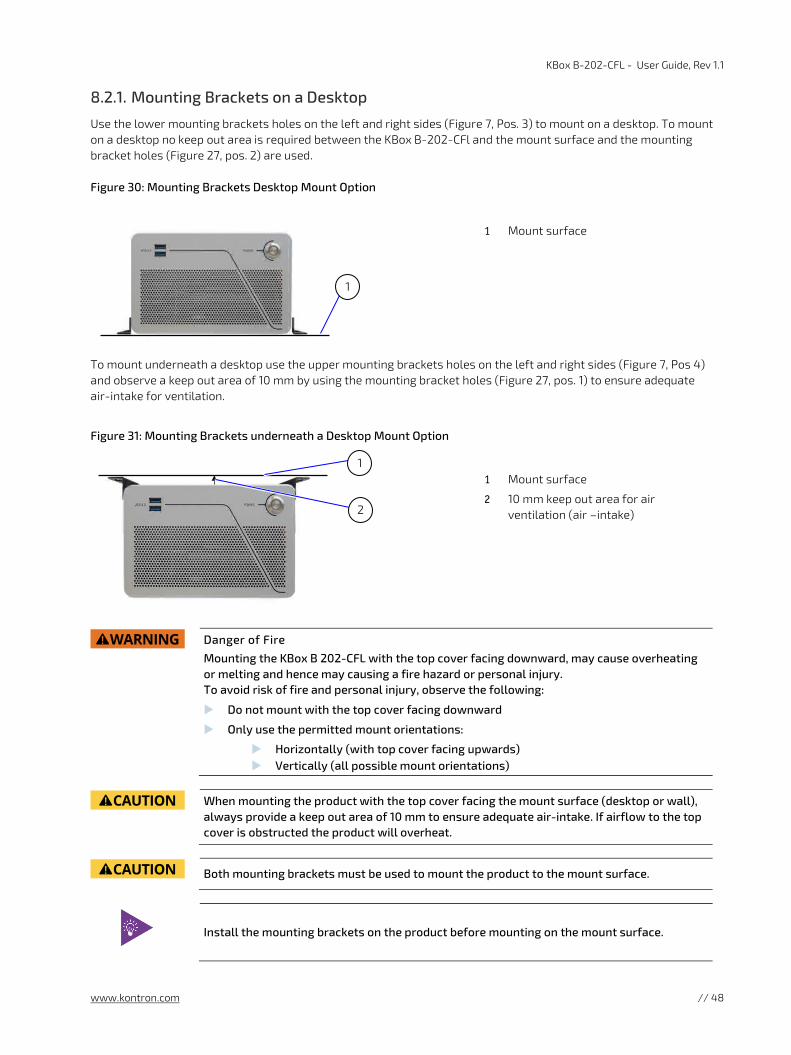
KBox B-202-CFL - User Guide, Rev 1.1
www.kontron.com // 48
8.2.1. Mounting Brackets on a Desktop
Use the lower mounting brackets holes on the left and right sides (Figure 7, Pos. 3) to mount on a desktop. To mount on a desktop no keep out area is required between the KBox B-202-CFl and the mount surface and the mounting bracket holes (Figure 27, pos. 2) are used.
Figure 30: Mounting Brackets Desktop Mount Option
1 Mount surface
To mount underneath a desktop use the upper mounting brackets holes on the left and right sides (Figure 7, Pos 4) and observe a keep out area of 10 mm by using the mounting bracket holes (Figure 27, pos. 1) to ensure adequate air-intake for ventilation.
Figure 31: Mounting Brackets underneath a Desktop Mount Option
1 Mount surface
2 10 mm keep out area for air ventilation (air –intake)
Danger of Fire
Mounting the KBox B 202-CFL with the top cover facing downward, may cause overheating or melting and hence may causing a fire hazard or personal injury. To avoid risk of fire and personal injury, observe the following:
Do not mount with the top cover facing downward
Only use the permitted mount orientations:
Horizontally (with top cover facing upwards) Vertically (all possible mount orientations)
When mounting the product with the top cover facing the mount surface (desktop or wall),
always provide a keep out area of 10 mm to ensure adequate air-intake. If airflow to the top cover is obstructed the product will overheat.
Both mounting brackets must be used to mount the product to the mount surface.
Install the mounting brackets on the product before mounting on the mount surface.
2
1
1

KBox B-202-CFL - User Guide, Rev 1.1
www.kontron.com // 49
8.2.2. Mounting Brackets on a Wall
Use the lower mounting holes on the left and right sides (Figure 7, pos. 3) to mount with the top cover facing outwards. No keep out area is required between the KBox B-202-CFl and the mount surface and the mounting bracket holes (Figure 27, pos. 2) are used.
Figure 32: Mounting Brackets Wall Mount Options with Bottom Side facing the Mounting Surface
Front panel (above) Front panel (below) Front panel (right) Front panel (left)
Use the upper mounting holes on the left and right sides (Figure 7, pos. 4) to mount with the top cover facing the mount surface. Observe a keep out area of 10 mm by using the mounting bracket holes (Figure 27, pos. 1) to ensure adequate air-intake for ventilation.
Figure 33: Mounting Brackets Wall Mount Options with Top Cover facing the Mounting Surface
l
Front panel (above) Front panel (below) Front panel (right) Front panel (left)
When mounting the product with the top cover facing the mount surface (desktop or wall),
always provide a keep out area of 10 mm to ensure adequate air-intake. If airflow to the top cover is obstructed the product may overheat.
Both mounting brackets must be used to mount the product to the mount surface.
Install the mounting brackets on the product before mounting on the mount surface.
KBox B-202-CFL - User Guide, Rev 1.1
www.kontron.com // 50
8.3. Connecting the Wi-Fi Antenna (option)
To use the Wi-Fi feature, install the two Wi-Fi antennas included in the scope of delivery to the two Wi-Fi antenna connectors on the rear side of the KBox B-202-CFL. Note that installing the Wi-Fi antenna increases the original keep out area on the rear side from 10 mm to approximately 45 mm.
To install the Wi-Fi antenna, perform the following:
1. Screw the Wi-Fi antenna on to the Wi-Fi antenna connector.
2. Position the Wi-Fi antenna, using the Wi-Fi antenna’s hinge, in the direction required or allowed for by the installation environment.
Installing the dual Wi-Fi antennas on the rear panel increases the keep out clearance to
45 mm and 130 mm from Wi-Fi hinge.

KBox B-202-CFL - User Guide, Rev 1.1
www.kontron.com // 51
9/ Starting Up Before switching on, observe the instructions in Chapter 1/: General Safety Instructions for IT Equipment and the instructions within this chapter.
Operate in closed condition only
It is only ensured that users do not have access to internal components during operation when the top cover is properly secured with the two top cover fastening screws.
Even when switched off using the power-on button, parts of the product are still energized!
The product is only completely switched off when power has been switched off using the power-on button and the power cable disconnected from the mains power supply or DC-IN connector.
Do not switch on or handle the product if there is any visible damage.
Do not disconnect the power while the product is switched on! This performs a forced
shutdown and may lead to loss of data! Switch off using the power-on button to perform an orderly shutdown without data loss.
9.1. Connecting to DC Power Supply
Only connect the KBox B-202-CFLto the supplied external AC/DC power supply chosen to
meet the products electrical specification, power consumption, power protection requirements and comply with the safety standards as stipulated by IEC 62368-1.
Following proper cabling procedures:
1. Grounding pin is connected first and disconnected last 2. Connect all I/O cables 3. Last connection is the power supply to DC-in and the AC mains power supply
Support I/O cables and power cables to minimize the strain on the product’s connectors.
To connect the power supply, perform the following:
1. Check that the top cover, drive bay cover and PCIe expansion card door are secured.
2. Connect the cables using proper cabling procedures by connecting the grounding pin, and then connecting the required I/O cables.
3. Connect the corresponding end of the power supply to the DC-IN connector on the rear panel (Figure 5, pos. 11 or Figure 6, pos. 11).
4. Connect the cable on the other end of the power supply to the mains power supply.

KBox B-202-CFL - User Guide, Rev 1.1
www.kontron.com // 52
9.2. Switching On /Off
Before switching on, read and observe the safety instructions at the start of this chapter. The power-on button switches on/off the KBox B-202-CFL. The power-on button includes an integrated power LED that lights up blue to indicate the powered on state.
To switch on, perform the following:
1. Press the Power-on button on the front panel (Figure 4, pos. 3).
2. The Power-on button’s LED lights up blue to indicate the powered on state.
Do not disconnect the power while the product is switched on. This performs a forced
shutdown and may lead to loss of data. Switch off using the power-on button to perform an orderly shutdown without data loss.
Pressing the power-on button for longer than four seconds initiates a forced system shutdown, before switching off the power. Once shutdown, users can restart by pressing the power-on button, if power is still applied to the DC-IN connector.
To switch off the product properly, perform the following:
1. Press the Power-on button on the front panel (Figure 4, pos. 3).
2. The Power-on button’s LED turns off to indicate the powered off state.
3. If required to switch off completely, disconnect the power cable from the mains power supply or the DC-in connector.
Even when switched off using the power-on button parts of the product are still energized!
The product is only completely switched off when power has been switched off using the power-on button and the power cable disconnected from the mains power supply or DC-IN connector.
9.3. Operating System (OS) and Hardware Component Drivers
The KBox B-202-CFL supports flexible software options with different Operating Systems (OS) and driver support for factory configured hardware components.
When ordered with a pre-installed OS and all appropriate drivers (in accordance with the ordered hardware configuration) the product is operational when switched on for the first time.
When ordered without a pre-installed OS, users must install the OS and the appropriate drivers (in accordance with the ordered hardware configuration) before switching on for the first time. Pay attention to the manufacturer’s OS specifications for integrated hardware components.
For information regarding supported software, see Table 12: Software Specification.
To download drivers for factory-installed hardware components, visit Kontron’s Customer Section.

KBox B-202-CFL - User Guide, Rev 1.1
www.kontron.com // 53
10/ Technical Data
10.1. Block Diagrams
Figure 34: Block Diagram of KBox B-202-CFL Smart Variant without Wi-Fi
KBox B-202-CFL (Smart)
Drive Bay 2.5" HDD/
SSD
mPCIe Socket(Gen 3)
M.2 SocketKey M
(4x PCIe lanes)
Legend Mainboard Chipset Internal connectors
External connectors
CPU Onboard memory
2x USB 3.1 Gen 2
4x USB 2.0
1x DVI-D
2x DisplayPort
1x Mouse PS/2
1x Keyboard PS/2
1x Serial Port
1x Audio (In/Out)
12 V DC-IN
PSU
External part
ChipsetIntel®Q370
Fan
Fan Connector
OnboardPart
Externally accessible
SATA Data
SATA Power
2x USB 3.1 Gen 1Front Panel
Connector
2x USB 3.1 Gen 1
2x LAN (GbE)
24 VDC (option)
PCIe Slots1x PCIe x16 or
2x PCIe x8
CPU 8th & 9th Den.Lntel® /ore™
i3 /i5/i7
Dual Channel DDR4-2666
UDIMM(up to 32 GB)
Power Button & Power LED
System

KBox B-202-CFL - User Guide, Rev 1.1
www.kontron.com // 54
Figure 35: Block Diagram of KBox B-202-CFL Value Variant without Wi-Fi
KBox B-202-CFL (Value)
Drive Bay 2.5" HDD/
SSD
mPCIe Socket(Gen 3)
M.2 SocketKey M
(4x PCIe lanes)
Legend Mainboard Chipset Internal connectors
External connectors
CPU Onboard memory
3x USB 2.0
1x DVI-D
1x DisplayPort
1x Mouse PS/2
1x Keyboard PS/2
1x Serial Port
1x Audio (In/Out)
12 V DC-IN
PSU
External part
ChipsetIntel®H310
Fan
Fan Connector
OnboardPart
Externally accessible
SATA Data
SATA Power
2x USB 3.1 Gen 1
Front Panel
Connector
2x USB 3.1 Gen 1
2x LAN (GbE)
24 VDC (option)
PCIe Slots1x PCIe x16
CPU 8th & 9th Den.Lntel® /ore™
i3 /i5/i7
Dual Channel DDR4-2666
UDIMM(up to 32 GB)
Power Button & Power LED
System
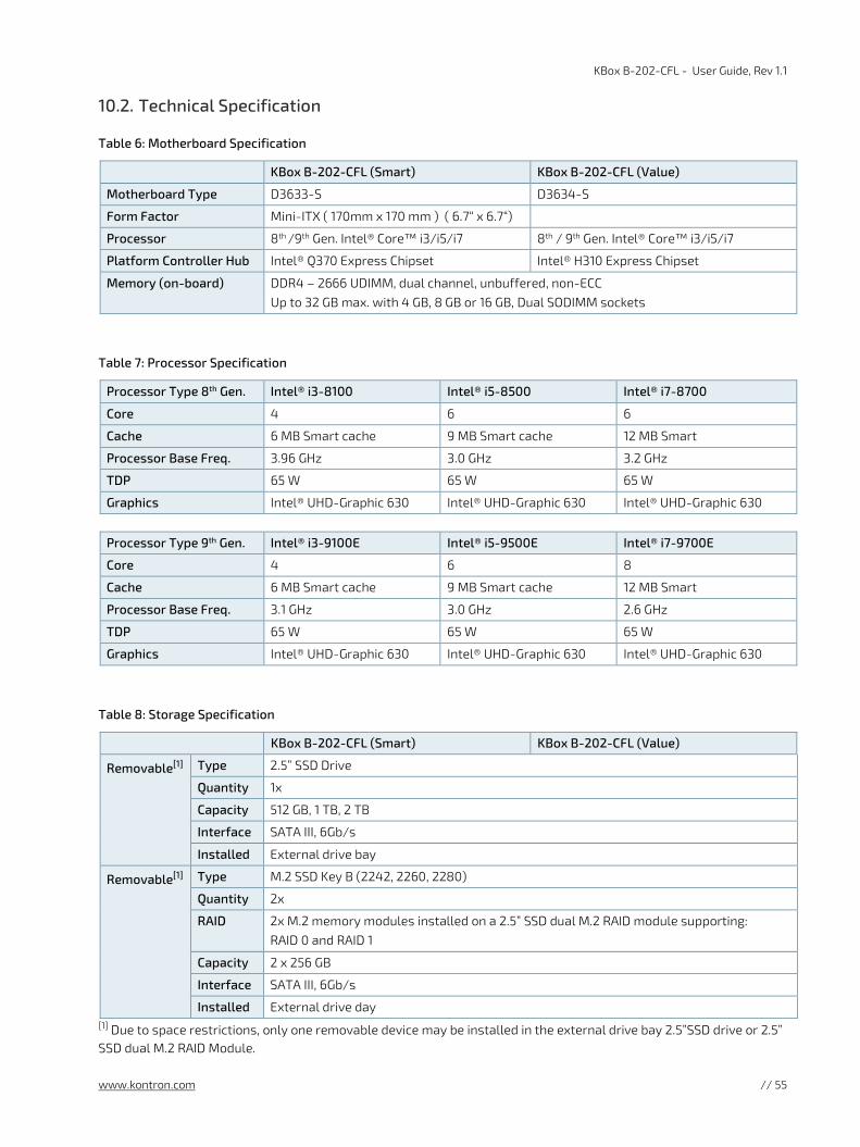
KBox B-202-CFL - User Guide, Rev 1.1
www.kontron.com // 55
10.2. Technical Specification
Table 6: Motherboard Specification
KBox B-202-CFL (Smart) KBox B-202-CFL (Value)
Motherboard Type D3633-S D3634-S
Form Factor Mini-ITX ( 170mm x 170 mm ) ( 6.7“ x 6.7“)
Processor 8th /9th Gen. Intel® Core™ i3/i5/i7 8th / 9th Gen. Intel® Core™ i3/i5/i7
Platform Controller Hub Intel® Q370 Express Chipset Intel® H310 Express Chipset
Memory (on-board) DDR4 – 2666 UDIMM, dual channel, unbuffered, non-ECC Up to 32 GB max. with 4 GB, 8 GB or 16 GB, Dual SODIMM sockets
Table 7: Processor Specification
Processor Type 8th Gen. Intel® i3-8100 Intel® i5-8500 Intel® i7-8700
Core 4 6 6
Cache 6 MB Smart cache 9 MB Smart cache 12 MB Smart
Processor Base Freq. 3.96 GHz 3.0 GHz 3.2 GHz
TDP 65 W 65 W 65 W
Graphics Intel® UHD-Graphic 630 Intel® UHD-Graphic 630 Intel® UHD-Graphic 630
Processor Type 9th Gen. Intel® i3-9100E Intel® i5-9500E Intel® i7-9700E
Core 4 6 8
Cache 6 MB Smart cache 9 MB Smart cache 12 MB Smart
Processor Base Freq. 3.1 GHz 3.0 GHz 2.6 GHz
TDP 65 W 65 W 65 W
Graphics Intel® UHD-Graphic 630 Intel® UHD-Graphic 630 Intel® UHD-Graphic 630
Table 8: Storage Specification
KBox B-202-CFL (Smart) KBox B-202-CFL (Value)
Removable[1] Type 2.5” SSD Drive
Quantity 1x
Capacity 512 GB, 1 TB, 2 TB
Interface SATA III, 6Gb/s
Installed External drive bay
Removable[1] Type M.2 SSD Key B (2242, 2260, 2280)
Quantity 2x
RAID 2x M.2 memory modules installed on a 2.5” SSD dual M.2 RAID module supporting: RAID 0 and RAID 1
Capacity 2 x 256 GB
Interface SATA III, 6Gb/s
Installed External drive day [1] Due to space restrictions, only one removable device may be installed in the external drive bay 2.5”SSD drive or 2.5” SSD dual M.2 RAID Module.

KBox B-202-CFL - User Guide, Rev 1.1
www.kontron.com // 56
KBox B-202-CFL (Smart) KBox B-202-CFL (Value)
Internal Type 2.5“ SSD Drive [2]
Quantity 2x
RAID Chipset RAID No Chipset RAID supported
Capacity 512 GB, 1 TB, 2 TB
Interface SATA III, 6Gb/s
Installed Internal cage
Internal Type M.2 SSD Key M
Quantity 1x
Capacity 2280 (1 TB / 512 GB) or 2242 (128 GB, / 256 GB)
Interface PCIe (Gen 3) @ 4 lanes PCIe (Gen 2) @ 2 lanes
Installed Motherboard M.2 socket [2] Due to internal space restrictions, the installation of internal 2.5” SSD drive(s) limits the number of usable PCIe slots to one.
Table 9: External Interface Specifications
KBox B-202-CFL (Smart) KBox B-202-CFL (Value)
Front side USB 3.0 2x USB 3.1 Gen 1
Rear side
USB 3.0 2x USB 3.1 Gen 1 2x USB 3.1 Gen 2
2x USB 3.1 Gen 1
USB 2.0 4x USB 2.0 3x USB 2.0
Display Port
2x DP V 1.2 (Resolution: 4096 x 2304 @ 60 Hz Max.)
1x DP V 1.2 (Resolution: 4096 x 2304 @ 60 Hz Max.)
DVI-D 1x DVI-D (Supports single link only)
LAN 2x LAN (GbE) 100/100/1000 Mb/s (Intel ® i219LM and i210AT)
Serial Port 1x COM1 (RS232 )
Audio Mic-Line-in & Line-out with HD Audio (Realtek ALC671)
PS/2 Mouse & Keyboard
DC-In +12 V DC or Industrial 24 VDC (future option)
Wi-Fi (option)
2x Antenna Factory configured with Kontron reference mPCIe Wi-Fi expansion card (half-size)
Table 10: Internal Expansion Slots
KBox B-202-CFL (Smart) KBox B-202-CFL (Value)
Type mPCIe
Quantity 1x
Size half-size or full-size mPCIe
Interface PCIe Gen 3 PCIe Gen 2
mPCIe (reference option) 802.11ac/abgn Dual-band 2T2R Wi-Fi + Bluetooth 4.0 technology Fi (mPCIe half-size)

KBox B-202-CFL - User Guide, Rev 1.1
www.kontron.com // 57
Table 11: External Expansion Slots
KBox B-202-CFL (Smart) KBox B-202-CFL (Value)
Quantity & Type 1x PCIe x16 or
2x PCIe x8 [1]
1x PCIe x16
Size full height, half-length PCIe full height, half-length PCIe
Interface PCIe Gen 3 PCIe Gen 2 [1] Due to internal space restrictions, the installation of internal 2.5” SSD drive(s) limits the number of usable PCIe slots to one.
The KBox B-202-CFL Value variant supports only one PCIe slot (1x PCIe x16).
Table 12: Software Specification
KBox B-202-CFL Smart KBox B-202-CFL Value
Operating System (OS) Windows® 10 Linux-64
Windows® 10 Linux-64
BIOS AMI Aptio 5.x (UEFI) BIOS (Modified and adapted for the motherboard )
UEFI only. No legacy support and no Master Boot Record (MBR) installation.
Table 13: Chassis Specification
Chassis Hot-dip zinc coated steel sheet (Black grey (RAL 7021))
Dimensions (D x W x H) 190 mm x 190 mm x 120 mm (7.48” x 7.48”) x 4.72“)
Front Panel Aluminum (Pearl light grey (RAL 9022))
Cooling Fan cooled, axial fan, silent fan

KBox B-202-CFL - User Guide, Rev 1.1
www.kontron.com // 58
10.3. Mechanical Specification
Table 14: Mechanical Specifications
KBox B-202-CFL Dimensions
Depth 190 mm (7.48”)
Width 190 mm (7.48”)
Height 120 mm (4.72”)
Weight (Without package) 2.8 kg (6.17 1 lbs.) approx.
Mounting Bracket (D x W x H)
187 mm x 45 mm x 20 mm (7.36” x 1.77” x 0.79”)
10.3.1. Dimension Diagrams
For more detailed mechanical information, refer to the outline dimension diagrams in this chapter. Each dimension drawing shows the main external mechanical dimensions.
Figure 36: Dimensions Front Panel Figure 37: Dimensions Rear Panel
190 mm 190 mm
120 mm

KBox B-202-CFL - User Guide, Rev 1.1
www.kontron.com // 59
Figure 38: Dimensions Top Cover
Figure 39: Dimensions Bottom Side
190 mm
190 mm
130 mm
190 mm 130 mm
190 mm

KBox B-202-CFL - User Guide, Rev 1.1
www.kontron.com // 60
Figure 40: Dimensions Right Side Figure 41: Dimensions Left Side
Figure 42: Dimensions with Mounting Brackets
10.4. Environmental Specification
Table 15: Environmental Specification
Temperature (Operating) 0°C - 45°C (32°F -- 113°F)
Temperature (Non-Operating) -20°C - +80°C (-4°F - 176°F)
Relative Humidity (Operating) 93% RH @ 40°C, non-condensing
Relative Humidity (Non-Operating) 93% RH @ 40°C, non-condensing
Altitude (Operating) 5000 m (16400 ft.) Max.
Noise 34 dB (A) @ 25°C Sea level, distance 1 m with full Processor/GPU load
Shock (Operating) Half sine, 15 g, 11 ms, half sine, acc. to IEC 60068-2-27
Vibration (Operating) 5 Hz - 500 Hz, 1 G acceleration, acc. to IEC 60068-2-6
160 mm 190 mm
11 mm
230 mm
250 mm
138 mm
10.5 mm
8.8 mm
26 mm 138 mm 37 mm
190 mm
201 mm
Ø 8.5
120 mm

KBox B-202-CFL - User Guide, Rev 1.1
www.kontron.com // 61
10.5. Directives and Standards
The KBox B-202-CFL complies with the European Council Directive and the approximation of the laws of the member states. When supplied with optional Wi-Fi, the KBox B-202-CFL complies with the Radio Equipment Directive (RED) and the approximation of the laws of the member states. If modified, the prerequisites for specific approvals may no longer apply.
Kontron is not responsible for any radio television interference caused by unauthorized modifications of the product or the substitution or attachment of connecting cables and equipment other than those specified by Kontron. The correction of interference caused by such unauthorized modification, substitution or attachment will be the responsibility of the user.
Table 16: Directives and Standards Compliance
CE (for KBox B-202-CFL- without Wi-Fi)
Council Directive 93/68/EEC
RED (for KBox B-202-CFL with Wi-Fi)
Draft ETSI EN 301 489-01 V2.2.0 EMC standard for radio equipment and services - Part 1: Common Technical Requirements
Final ETSI EN 301 489-17 V3.2.0 EMC standard for radio equipment and services – Part 17: Specific Conditions for Broadband Data Transmission Systems
ETSI EN 300 328 V2.1.1
Wideband transmission systems; Data transmission equipment operating in the 2,4 GHz ISM band and using wide band modulation techniques
ETSI EN 301 893 V2.1.1 5 GHz RLAN
EMC
Emission (Class B)
EN 55032:2012 / CISPR 32 Edition 2.0
Electromagnetic compatibility of multimedia equipment- Emission requirements
EN 61000-3-2:2014 Limits for harmonic currents emissions
EN 61000-3-3:2013 Limitations of voltage changes, voltage fluctuations and flicker in public low-voltage supply systems
Immunity (Industrial Equipment)
EN 55024:2010 / CISPR 24 Edition 2.1
Information technology equipment- Immunity characteristics
Safety
Europe EN 62368-1:2014
Audio/video, information and communication technology equipment – Safety requirements
CB Scheme CB Certificate - IEC 62368-1:2014
USA & Canada
NRTL -UL 62368-1:2014 CAN/CSA-C22.2 No. 62368-1:2014
FCC
FCC 47 CFR Part 15B/ ICES-003
Complies with the requirements of Federal Communications Commission (FCC) rules and regulations of title 47 of the Code of Federal Regulations (CFR) Part 15B and ICES-003:2017 & 2016 rules to limit the potential of harmful interference
Environment
WEEE Compliant with the Waste Electrical and Electronic Equipment (WEEE) 2012/19/EU directive; to reduce waste of electrical and electronic equipment, encourage recycling and environmental disposal and increase the environmental awareness of producers

KBox B-202-CFL - User Guide, Rev 1.1
www.kontron.com // 62
Environment
RoHS II Compliant with the Restriction of Hazardous Substances (RoHS) 2011/65/EU directive or the late status thereof, to reduce hazardous substances in electrical and electronic equipment
REACH Compliant with the Registration, Evaluation, Authorization and Restriction of Chemicals (REACH) Regulation No. 1907/2006 to identify the intrinsic properties of chemical substances earlier
All tests were performed with the supplied external AC/DC power supply. Failure to use the supplied power supply may invalidate the FCC compliance and class. The use of shielded I/O cables are required when connecting to peripheral or host devices. Failure to do so may violate FCC/ICES rules.
10.6. Power Specification
The external AC/DC Power Supply delivered with the KBox B-202-CFL is an AC/DC, 150 W PSU, supplying a nominal output voltage of 12 VDC. Only use the power supply delivered with the product and chosen to meet the product’s electrical power specification, power consumption and power protection requirements. The motherboard generates all other required voltages.
Table 17: Power Supply Electrical Specification
Power Supply Type External AC /DC (150 W)
Dimensions 151.3 mm x 75.6 mm x 25.4 mm (5.96” x 2.98” x 1”)
Input Voltage 100 VAC to 240 VAC
Input Current < 2 A max. (full load)
Efficiency 87% (100 VAC, 12.5 A load) / 88% (240 VAC, 12.5 A load)
Output Power 150 W
Output Voltage 12 VDC
Output Current 12.5 A max. (150 W)
Only connect the KBox B-202-CFLto the supplied external AC/DC power supply chosen to
meet the products electrical specification, power consumption, power protection requirements and comply with the safety standards as stipulated by IEC 62368-1.
10.6.1. Power Consumption
The external AC/DC Power Supply delivered with the KBox B-202-CFL provides the level of power required to meet the power consumption. The overall power consumption depends on the motherboard capacity, system memory and system expansion and including all devices must not exceed the maximum power supply rating of 150 W. If the use of expansion cards increases the power consumption above 150 W, contact Kontron Support.
Table 18: Power Consumption Estimation
Components Maximum Power Consumption
Motherboard + Processor + RAM 96 W
SSD 4 W
Total 100 W

KBox B-202-CFL - User Guide, Rev 1.1
www.kontron.com // 63
10.6.2. Power Protection
The external AC/DC Power Supply delivered with the KBox B-202-CFL supports the power protection features required to protect the KBox B-202-CFL from damage or loss of data.
Power protection features such as holdup time and brownout protect against peaks, fluctuations and interruptions in the mains power supply voltage, and help ensure operation without loss of data or damage to the product.
Table 19: Power Supply Protection Features
Amount Description
Holdup Time ≥10 sec Condition : @ 100 VAC or 240 VAC / 12.5 A full load, output voltage remains regulated
Amount of time the power supply can bridges drops in mains voltage without fluctuations in the power supply’s output voltage.
Brownout 60 VAC to 70 VAC Voltage Level at which the power supply is in an under voltage condition due to a drop in the mains voltage
If there is an unintentional voltage drop in the mains power supply for longer than the specified holdup time (brownout), all supply voltages should be shut down and remain in the off state for long enough to allow internal voltages to discharge sufficiently. During the off state time do not disconnect or add cables to/from the I/O connectors. Failure to observe this off state time means that parts of the product or attached peripherals may work incorrectly or suffer a reduction of MTBF.
The minimum off state time, depends on the power supply model and additional electrical factors. To determine the required off state time, each case must be considered individually. For more information, contact Kontron Support.
10.6.3. Ground
Grounding pin connects to the internal chassis GND. The grounding pin is located on the bottom right hand side of the rear panel (Figure 5, pos. 17 or Figure 6, pos. 17).

KBox B-202-CFL - User Guide, Rev 1.1
www.kontron.com // 64
11/ External Interface - Pin Assignments
11.1. DC IN Power Connector Pin Assignment
The DC IN power connector is a barrel jack (5.5 mm/ 2.5 mm) with center pole and an input voltage of 12 V only.
Table 20: DC Power Jack Pin Assignment
Pin Signal Name Power Jack
Centre pole 12 V
Outer ring Ground
Hot plugging the power connectors might damage the board and is not allowed.
When connecting to the product, switch off the mains supply to make sure all power lines are switched off.
Only connect the external AC/DC power supply chosen to meet the products electrical
specification, power consumption, power protection requirements and comply with the safety standards as stipulated by IEC 62368-1.
11.2. USB 3.1 Gen 1 Port & USB 3.1 Gen 2 Pin Assignment
Table 21: USB 3.1 Connector Pin Assignment
Pin Signal Name Pin Signal Name 9-pin USB 3 (Type A) Port
1 +5V (fused protected)
5 RX- 9 5
USB 3.1 Gen 1 1 4
9 5
USB 3.1 Gen 2 1 4
2 Date-
6 RX+
3 Data+
7 GND
4 GND
8 TX-
9 TX+
Low-active signals are indicated by a minus sign.

KBox B-202-CFL - User Guide, Rev 1.1
www.kontron.com // 65
11.3. USB 2.0 Port Pin Assignment
Table 22: USB 2.0 Connector Pin Assignment
Pin Signal Name USB 2.0 Connector( Type A)
1 +5 V (fused protected)
1 4
2 Data-
3 Data+
4 GND
Low-active signals are indicated by a minus sign.
11.4. LAN Connector Pin Assignment
Table 23: LAN (GbE) Connector Pin Assignment
Low-active signals are indicated by a minus sign.
Table 24: LAN Link Activity
Speed (Mbps) LINK/ACT
LINK Link and Activity
10 off on blinking
100 green on blinking
1000 Yellow on blinking
Pin Signal Name (10/100/1000)
Signal Name (10/100)
LAN1 and LAN2 Connector (RJ45)
1 MX1+ TX+
2 MX1- TX-
3 MX2+ RX+
4 MX3+ TERMPLANE
5 MX3- TERMPLANE
6 MX2- RX-
7 MX4+ TERMPLANE
8 MX4- TERMPLANE
1 8
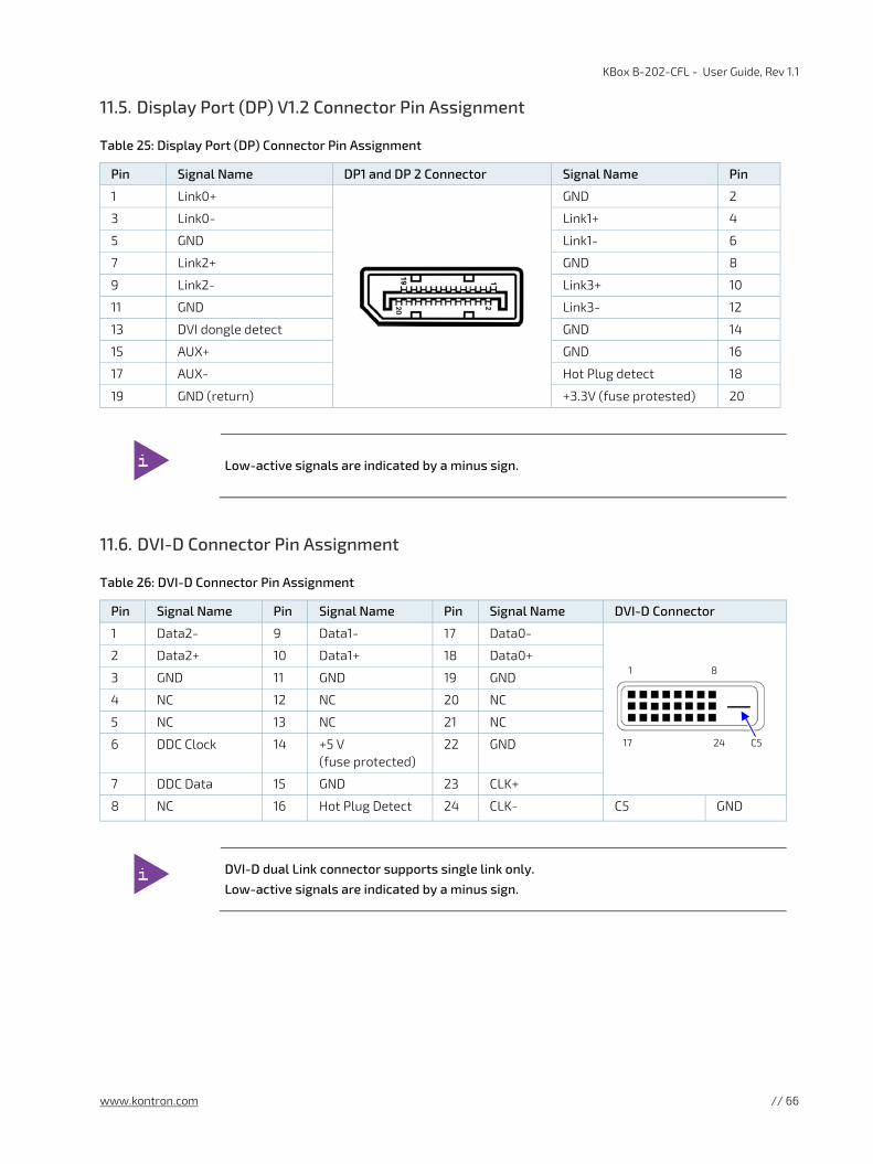
KBox B-202-CFL - User Guide, Rev 1.1
www.kontron.com // 66
11.5. Display Port (DP) V1.2 Connector Pin Assignment
Table 25: Display Port (DP) Connector Pin Assignment
Pin Signal Name DP1 and DP 2 Connector Signal Name Pin
1 Link0+
GND 2
3 Link0- Link1+ 4
5 GND Link1- 6
7 Link2+ GND 8
9 Link2- Link3+ 10
11 GND Link3- 12
13 DVI dongle detect GND 14
15 AUX+ GND 16
17 AUX- Hot Plug detect 18
19 GND (return) +3.3V (fuse protested) 20
Low-active signals are indicated by a minus sign.
11.6. DVI-D Connector Pin Assignment
Table 26: DVI-D Connector Pin Assignment
Pin Signal Name Pin Signal Name Pin Signal Name DVI-D Connector
1 Data2- 9 Data1- 17 Data0- 1 8
17 24 C5
2 Data2+ 10 Data1+ 18 Data0+
3 GND 11 GND 19 GND
4 NC 12 NC 20 NC
5 NC 13 NC 21 NC
6 DDC Clock 14 +5 V (fuse protected)
22 GND
7 DDC Data 15 GND 23 CLK+
8 NC 16 Hot Plug Detect 24 CLK- C5 GND
DVI-D dual Link connector supports single link only.
Low-active signals are indicated by a minus sign.

KBox B-202-CFL - User Guide, Rev 1.1
www.kontron.com // 67
11.7. PS/2 Keyboard Connector Pin Assignment
Table 27: PS/2 Keyboard Connector Pin Assignment
11.8. PS/2 Mouse Connector Pin Assignment
Table 28: PS/2 Mouse Connector Pin Assignment
11.9. Audio Line-out and Audio Line-in Connector Pin Assignment
Table 29: Audio Line-OUT Audio Line-IN Pin Assignment
Connector Signal Name Audio Barrel Connector
Green Line-OUT
Blue Line-IN
Supports HD audio and legacy audio.
For legacy support, select the legacy option in the BIOS setup menu.
Pin Signal Name PS/2 KBD Connector
1 Data
2 NC
3 GND
4 +5V (fuse protected)
5 Clock
6 Keyboard_On (low asserted pulse)
Pin Signal Name PS/2 Mouse Connector
1 Data
2 NC
3 GND
4 +5V (fuse protected)
5 Clock
6 NC

KBox B-202-CFL - User Guide, Rev 1.1
www.kontron.com // 68
11.10. Serial Port Connector Pin Assignment
Table 30: Serial Interface COM port (RS232) Connector Pin Assignment
Pin Signal Name Description 9-pin D-SUB Connector
1 DCD Data Carrier Detect
1 5
6 9
2 SIN Signal IN
3 SOUT Signal OUT
4 DTR Data Terminal Ready
5 GND Ground
6 DSR Data Set Ready
7 RTS Request to Send
8 CTS Clear to Send
9 RI Ring Indicator

KBox B-202-CFL - User Guide, Rev 1.1
www.kontron.com // 69
12/ BIOS The KBox B-202-CFL uses the AMI Aptio 5.x (UEFI) BIOS supported by the D3633-S and D3634-S motherboards and featuring a variety of enhanced functions specifically tailored to the KBox B-202-CFL’s hardware features:
Recovery BIOS
SM-BIOS (DMI)
BIOS and CPU Microcode Update
Quick boot
LOGO boot
Quite boot
Plug & Play
Automatic DRAM and PCIE configuration
BIOS support for S.M.A.R.T.
Advanced Power Management
ACPI S3/S4
Wake on time from S5
HW watchdog support & BIOS integrated HW Diagnostic tool
Silent fan
For security, the following BIOS features are available:
System and BIOS password
Boot sequence control
Serial /USB-port access protection
Boot sector virus warning
Write protection for FLASH BIOS
Erase Disk
Intel® Integrated TPM V2.0
uEFI only! No legacy support and no Master Boot Record (MBR) installation.
BIOS features in this user guide are open to change and may not be available in the latest version of the motherboard’s BIOS, see Chapter 12.2: BIOS Update.
12.1. Starting the uEFI BIOS
The uEFI BIOS comes with a setup program that provides quick and easy access to the individual function settings for control or modification of the uEFI BIOS configuration. The setup program allows for access to various menus that provide functions or access to sub-menus with further specific functions.
To start the uEFI BIOS setup program, perform the following:
1. Power-up the product.
2. Wait until the first characters appear on the screen (POST messages or splash screen).
3. Press the <DEL> key repeatedly.

KBox B-202-CFL - User Guide, Rev 1.1
www.kontron.com // 70
4. Enter the User Password or Supervisor Password, and press <RETURN>, if the uEFI BIOS is password protected.
5. The setup menu appears.
If the <DEL> key is not press the POST continues with the test routines.
The KBox B-202-CFL uEFI BIOS setup program uses a hot key navigation system. The hot key legend bar is located at the bottom of the setup screens. The following table provides a list of navigation hot keys available in the legend bar.
Table 31: Navigation Hot Keys Available in the Legend Bar
Sub-screen Description
<F1> <F1> key invokes the General Help window
<-> <Minus> key selects the next lower value within a field
<+> <Plus> key selects the next higher value within a field
<F2> <F2> key loads previous values
<F3> <F3> key loads optimized defaults
<F4> <F4> key Saves and Exits
<→> or <←> <Left/Right> arrows selects major setup menus on menu bar, for example, Main or Advanced
<↑> or <↓> <Up/Down> arrows select fields in the current menu, for example, setup function or sub-screen
<ESC> <ESC> key exits a major setup menu and enters the Exit setup menu Pressing the <ESC> key in a sub-menu displays the next higher menu level
<RETURN> <RETURN> key executes a command or selects a submenu
12.2. BIOS Update
To ensure compatibility with new OS, hardware, software or to integrate new BIOS functions Kontron recommends regular BIOS updates. Additionally, if a problem cannot be solved using a new driver, Kontron recommends updating the BIOS. To check if a BIOS update is available for the KBox B-202-CFL Smart or KBox B-202-CFL Value, visit Kontron’s Customer Section.
The BIOS update required depends on the motherboard. For the motherboard product names for the KBox B-202-CFL Smart or Value, see Table 6: Motherboard Specification.
Before updating the BIOS, make a backup of the current BIOS setting. After a BIOS update, additional modifications must be made manually.
During a BIOS update, do not switch off, reset or interrupt the process. If interrupted, the BIOS update process must be restarted.
If the product fails to boot after a BIOS update, the updated BIOS maybe damaged. For more information, contact Kontron Support.

KBox B-202-CFL - User Guide, Rev 1.1
www.kontron.com // 71
13/ RAID The KBox B-202-CFL supports up to two RAID array options. The 2.5” SSD dual M.2 RAID module with two M.2 SSDs is installed in the external drive bay and is hardware configured to RAID 1 or 0. The two 2.5” SSD drives are installed in the internal card cage and are hardware configured as RAID 1 or 0. For more information regarding RAID features, see Table 32 and refer to either Chapter 13.1: iRAID Utility Software or Chapter 13.2: Chipset RAID.
Table 32: RAID Options with Features
RAID Features 2.5” SSD dual M.2 RAID module Internal 2.5” SSD drives with Chipset RAID
Drive type 1x SSD dual M.2 RAID Module with 2x M.2 Key B SSD modules
2x 2.5” SSD drives (factory installed)
Interface SATA III, 6Gb/s interface SATA III, 6Gb/s interface
Position External drive bay (removable) Internal cage
RAID Type RAID 0 and RAID 1 (default RAID1) (hardware configurable)
RAID 0 and RAID 1 with Chipset RAID[1]
(software configurable)
RAID Software iRAID utility software (pre-installed) Intel® RST Monitoring[1] [1] Only the KBox B-202-CFL Smart variant supports Chipset RAID on the internal 2.5” SSD drives.
13.1. iRAID Utility Software
The 2.5” SSD dual M.2 RAID module uses the manufacture’s iRAID Utility pre-installed software to monitor the status of the RAID module’s individual drives and enables users to access data regarding the RAID settings, receive notifications, and find out about memory events that occurred and could lead to a possible drive failure.
13.1.1. Settings
Displays the main RAID data for both drives:
Drive model
Serial number (SN)
Firmware
Memory capacity
S.M.A.R.T health check information
The S.M.A.R.T health check helps predict memory failures by counting how often memory-attribute problems occur, see Table 33: S.M.A.R.T. Information Memory Attributes.
Table 33: S.M.A.R.T. Information Memory Attributes Examples
Memory-attributes
Later bad Average erase Unexpected power loss
Power on hours Device Life Temperature
Power cycle Spare block Flash ID
Total bad block Program fail Later bad block read
Maximum erase Erase fail Later bad block write

KBox B-202-CFL - User Guide, Rev 1.1
www.kontron.com // 72
13.1.2. Notifications
Notifications enables users to set an email address to receive notification emails for typical RAID events, when a specified threshold level is reached.
Table 34: Notifications Examples
Notifications
RAID Broken RAID Created RAID 1 Rebuild Finished
RAID Degrade RAID Deleted RAID 1 Rebuild Suspend
RAID Recovery RAID 1 Rebuild RAID 1 Rebuild Error
13.1.3. Events
Events lists important RAID events and gives more detailed information:
Table 35: Event List Examples
Events Description
List number Lists in the order of occurrence
Type Type of event Info./ Alert / Error
Time Time the event took place
Event Event’s RAID notification tag
Message Describes the error in more detail e.g. H/W RAID 1 DISK 1 plugged out or DISK one plugged in
13.2. Chipset RAID
To configure the two internal 2.5” SSDs using Chipset RAID, perform the following:
1. Enter the BIOS setup menu, see Chapter 12.1: Starting the uEFI BIOS.
2. Navigate to the Advance > Drive Configuration and change from AHCI to RAID.
3. Navigate to Save &Exit > Save Changes and Exit.
4. Restart and re-enter the BIOS setup menu.
5. Navigate to the newly created RAID Submenu Advanced>RAID and enter the RAID array type: RAID 1 or RAID 0.
6. Navigate to Save &Exit > Save Changes and Exit.
7. To monitor the Chipset RAID array, download and install the motherboard’s Intel® Rapid Storage Technology driver.

KBox B-202-CFL - User Guide, Rev 1.1
www.kontron.com // 73
14/ Technical Support Should a problem occur that cannot be solved using the trouble shooting information above contact Kontron’s Support Department:
Email: [email protected]
Phone: +49-821-4086-888
Make sure you have the following information available when you call:
Product ID Number (PN)
Serial Number (SN)
The serial number can be found on the products type label.
Be ready to explain the nature of your problem to the service technician.
14.1. Returning Defective Merchandise
All equipment returned to Kontron must have a Return of Material Authorization (RMA) number assigned exclusively by Kontron. Kontron cannot be held responsible for any loss or damage caused to the equipment received without an RMA number. The buyer accepts responsibility for all freight charges for the return of goods to Kontron's designated facility. Kontron will pay the return freight charges back to the buyer's location in the event that the equipment is repaired or replaced within the stipulated warranty period.
Follow these steps before returning any product to Kontron.
1. Visit the RMA Information website: http://www.kontron.com/support-and-services/support/rma-information
2. Download the RMA Request sheet for Kontron Europe GmbH – Augsburg and fill out the form. Take care to include a short detailed description of the observed problem or failure and to include the product identification Information (Name of product, Product number and Serial number). If a delivery includes more than one product, fill out the above information in the RMA Request form for each product. Send the completed RMA-Request form to the fax or email address given on the RMA Request sheet and Kontron will provide an RMA-Number.
3. The goods for repair must be packed properly for shipping, considering shock and ESD protection.
Goods returned to Kontron in non-proper packaging will be considered as customer caused faults and cannot be accepted as warranty repairs.
4. Include the RMA-Number with the shipping paperwork and send the product to the delivery address provided in the RMA form or received from Kontron RMA Support.

KBox B-202-CFL - User Guide, Rev 1.1
www.kontron.com // 74
15/ Storage, Transportation and Maintenance
15.1. Storage
If the product is not in use for an extended period time, disconnect the product from the main power supply .If it is necessary to store the product then repack the product as originally delivered to avoid damage. The storage facility must meet the products environmental storage requirements as stated within this user guide. Kontron recommends keeping the original packaging material for future storage or warranty shipments.
15.2. Transportation
To ship the product use the original packaging, designed to withstand impact and adequately protect the product. When packing or unpacking products always take shock and ESD protection into consideration and use an EOS/ESD safe working area.
15.3. Maintenance
Maintenance or repair on the open product may only be carried out by trained personnel authorized by Kontron. Kontron products require only minimum servicing and maintenance for problem-free operation.
To clean the surface of the chassis, carefully remove dust using a clean soft brush and for light soiling clean the product with a dry cloth. Remove stubborn dirt using a mild detergent and a soft cloth.
Handling and operation of the product is permitted only for trained personnel aware of the
associated dangers, within a work place that is access controlled and fulfills all necessary technical and environmental requirements.
15.3.1. Replacing the Lithium Battery
The lithium battery CR 2032 must be replaced with an identical 3 Volt battery or a Kontron recommended battery. To replace the on-board Lithium battery, perform the following:
1. Remove the lithium battery from the holder by pulling the ejector spring outwards.
2. Place a new lithium battery into the battery holder.
3. Pay attention to the polarity of the battery.
Danger of explosion when replaced with wrong battery type. Replace only with the same or
equivalent type recommended by the manufacturer. The lithium battery type must be UL recognized.
Do not dispose of lithium batteries in general trash collection. Dispose of the battery according to the local regulations dealing with the disposal of these special materials, (e.g. to the collecting points for dispose of batteries).

KBox B-202-CFL - User Guide, Rev 1.1
www.kontron.com // 75
16/ Warranty Kontron defines product warranty in accordance with regional warranty definitions. Claims are at Kontron’s discretion and limited to the defect being of a material nature. To find out more about the warranty conditions and the defined warranty period for your region, following the steps below:
1. Visit Kontron’s Term and Conditions webpage.
http://www.kontron.com/terms-and-conditions
2. Click on your region’s General Terms and Conditions of Sale.
16.1. Limitation/Exemption from Warranty Obligation
In general, Kontron shall not be required to honor the warranty, even during the warranty period, and shall be exempted from the statutory accident liability obligations in the event of damage caused to the product due to failure to observe the following:
General safety instructions for IT equipment within this user guide.
Warning labels on the product and warning symbols within this user guide.
Information and hints within this user guide.
Additionally, alterations or modifications to the product that are not explicitly approved by Kontron, described in this user guide, or received from Kontron Support as a special handling instruction will void your warranty.
Due to their limited service life, parts that by their nature are subject to a particularly high degree of wear (wearing parts) are excluded from the warranty beyond that provided by law.

KBox B-202-CFL - User Guide, Rev 1.1
www.kontron.com // 76
Appendix A: List of Acronyms
Table 36: List of Acronyms
ACPI Advanced Configuration Power Interface
AHCI Advanced Host Controller Interface
BIOS Basic Input Output System
BT BlueTooth
CFR Code of Federal Regulations
COM Communication port
DP Display Port
DRAM Dynamic RAM
DVI Digital Video Interface
ECC Error Checking and Correction
ECT Embedded Computer Technology
EEE Electrical and Electronic Equipment
ESD Electro Static Device
FCC Federal Communications Commission
GbE Giga bit Ethernet
GPU Graphics Processing Unit
HD High Definition
HD/HDD Hard Disk /Drive
ICES Interference Causing Equipment Standard
IOT Internet of Things
ITE Information Technology Equipment
KBD Keyboard
LAN Local Area Network
LED Light-Emitting Diode
LVDs Low Voltage Device
MTBF Mean Time Before Failure
NC-SI Network Controller Sideband Interface
PCIe PCI-Express
mPCIe Mini PCI-Express
OS Operating System
PSU Power Supply Unit
RAID Redundant Array of Independent Disks
RAM Random Access memory
REACH Registration, Evaluation, Authorization and Restriction of Chemicals
RED Radio Equipment Directive
RMA Return of Material Authorization
ROHS Restriction Of Hazardous Substances
RTC Real Time Clock
SATA Serial AT Attachment
mSATA Mini SATA
SELV Separate Extra Low Voltage
S.M.A.R.T Self-Monitoring, Analysis and Reporting Technology
SN Serial Number
S/PDIF Sony/Philips Digital Interface
SSD Solid State Drive
TPM Trusted Platform Module
UEFI Unified Extensible Firmware Interface
USB Universal Serial Bus
VCC Voltage Common Collector
VDC Voltage Direct Current
WEEE Waste Electrical and Electronic Equipment
Wi-Fi Wireless
WSXGA Wide Super eXtended Graphics Array
WQXGA Wide Quad eXtended Graphics Array
XGA eXtended Graphics Array

KBox B-202-CFL – User Guide, Rev 1.1
www.kontron.com // 77
About Kontron Kontron is a global leader in embedded computing technology (ECT). As a part of technology group S&T, Kontron offers a combined portfolio of secure hardware, middleware and services for Internet of Things (IoT) and Industry 4.0 applications. With its standard products and tailor-made solutions based on highly reliable state-of-the-art embedded technologies, Kontron provides secure and innovative applications for a variety of industries. As a result, customers benefit from accelerated time-to-market, reduced total cost of ownership, product longevity and the best fully integrated applications overall. For more information, please visit: www.kontron.com
Global Headquarters
Kontron S&T AG
Lise-Meitner-Str. 3-5 86156 Augsburg Germany Tel.: + 49 821 4086-0 Fax: + 49 821 4086-111 [email protected]