ke basin sand filter media hazard categorization · pdf fileto provide the basis for the final...
TRANSCRIPT

PNNL-15403
Assessment of the KE Basin Sand Filter Inventory In Support of Hazard Categorization SB Ross J Young September 2005 Prepared for the U.S. Department of Energy under Contract DE-AC05-76RL01830
DISCLAIMER This report was prepared as an account of work sponsored by an agency of the United States Government. Neither the United States Government nor any agency thereof, nor Battelle Memorial Institute, nor any of their employees, makes any warranty, express or implied, or assumes any legal liability or responsibility for the accuracy, completeness, or usefulness of any information, apparatus, product, or process disclosed, or represents that its use would not infringe privately owned rights. Reference herein to any specific commercial product, process, or service by trade name, trademark, manufacturer, or otherwise does not necessarily constitute or imply its endorsement, recommendation, or favoring by the United States Government or any agency thereof, or Battelle Memorial Institute. The views and opinions of authors expressed herein do not necessarily state or reflect those of the United States Government or any agency thereof. PACIFIC NORTHWEST NATIONAL LABORATORY operated by BATTELLE for the UNITED STATES DEPARTMENT OF ENERGY under Contract DE-AC05-76RL01830 Printed in the United States of America Available to DOE and DOE contractors from the Office of Scientific and Technical Information,
P.O. Box 62, Oak Ridge, TN 37831-0062; ph: (865) 576-8401 fax: (865) 576-5728
email: [email protected] Available to the public from the National Technical Information Service, U.S. Department of Commerce, 5285 Port Royal Rd., Springfield, VA 22161
ph: (800) 553-6847 fax: (703) 605-6900
email: [email protected] online ordering: http://www.ntis.gov/ordering.htm
This document was printed on recycled paper.
(9/2003)
PNNL-15403
Assessment of the KE Basin Sand Filter Inventory In Support of Hazard Categorization
S. B. Ross J. Young
September 28, 2005
Prepared for Fluor Hanford PNNL Project Numbers 49528 and 46980 Pacific Northwest National Laboratory Richland, Washington 99352

Executive Summary In 1978, the water cleaning system for the KE Basin was upgraded by adding a sand filter and ion exchange columns. Basin water containing finely divided solids is collected by three surface skimmers and pumped to the sand filter. Filtrate from the sand filter is further treated in the ion exchange modules. The suspended solids accumulate in the sand until the pressure drop across the filter reaches established operating limits, at which time the sand filter is backwashed. The backwash is collected in the north loadout pit (NLOP), where the solids are allowed to settle as sludge. Figure 2-1 shows a basic piping and instrumentation diagram depicting the relationship among the basin skimmers, sand filter, and NLOP. During the course of deactivation and decommissioning (D&D) of the K-Basins, the sand filter and its media will need to be dispositioned. The isotopic distribution of the sludge in the sand filter has been estimated in KE Basin Sand Filter Monolith DQO (KBC-24705). This document estimates the sand filter contribution to the KE hazard categorization using the data from the DQO. The initial hazard category contribution of the KE Basin sand filter is Hazard Category 3. However, DOE-STD-1027-92 specifies that the final hazard categorization for a facility can consider the dispersibility of the radioactive inventory. This is done by adjusting the threshold quantity values for each radionuclide up or down based on the form and dispersibility of the inventory compared to assumptions made in determination of the DOE-STD-1027-92 threshold quantity values. To provide the basis for the final hazard categorization, a hazard analysis of D&D activities and inventories was done to identify bounding unmitigated accidents that could result in the dispersal of the radioactive material from within the basin facility. The final hazard category determinations reported here in Table ES-1 consider airborne release fractions, respirable fractions, and damage ratios based on bounding unmitigated accidents for D&D activities.
Table ES-1 -Sand Filter Inventory Hazard Categorization Initial Hazard Categorization
Final Hazard Categorization
Inventory Hazard
Category 2 Ratio
Hazard Category 3
Ratio
Hazard Category
Hazard Category 3
Ratio (seismic-induced
fire)
Hazard Category 3
Ratio (spray
release)
Hazard Category
SF DQO 4.5E-02 5.3E+00 HC-3 2.8E-01 8.1E-01 <HC-3
iii

Contents
EXECUTIVE SUMMARY .........................................................................................................................................3 TABLES .......................................................................................................................................................................4 1.0 PURPOSE ......................................................................................................................................................1 2.0 SCOPE ...........................................................................................................................................................2 3.0 HAZARD CATEGORIZATION METHODS............................................................................................3 3.1 INITIAL HAZARD CATEGORIZATION.................................................................................................3 3.2 FINAL HAZARD CATEGORIZATION....................................................................................................3 3.3 ACCIDENT CONSEQUENCES..................................................................................................................4 4.0 HAZARD CATEGORIZATION RESULTS ..............................................................................................6 4.1 RADIONUCLIDE INVENTORY................................................................................................................6 4.2 INITIAL HAZARD CATEGORIZATION RESULTS .............................................................................8 4.3 BOUNDING UNMITIGATED ACCIDENT SELECTION ......................................................................8 4.4 FINAL HAZARD CATEGORIZATION RESULTS.................................................................................8 4.4.1 ACCIDENT ANALYSIS: SEISMIC INDUCED FIRE .............................................................................8 4.4.2 ACCIDENT ANALYSIS: SPRAY RELEASE .........................................................................................13 4.5 CONSEQUENCE ASSESSMENT.............................................................................................................18 4.5.1 ANALYSIS FOR THE KE BASIN SAND FILTER SEISMIC INDUCED FIRE.................................18 4.5.2 ANALYSIS FOR THE KE BASIN SAND FILTER SPRAY RELEASE...............................................21 5.0 CONCLUSIONS..........................................................................................................................................26 6.0 REFERENCES............................................................................................................................................27
TABLES
Table ES-1 -Sand Filter Inventory Hazard Categorization............................................................. 3
Table 1 - Initial Hazard Categorization for the KE Sand Filter based on KBC-24705 ................. 6
Table 2. Parameters for Determination of TQV (adj ) for the Seismic Induced Fire. ................... 9
Table 3. Hazard Categorization Based on the Seismic Induced Fire........................................... 11
Table 4. Parameters for Determination of TQV (adj ) for the Spray Release. ............................. 14
Table 5. Hazard Categorization Based on the Spray Release. .................................................... 16
iv

1.0 Purpose During the course of deactivation and decommissioning (D&D) of the K-Basins, the KE Basin sand filter will need to be dispositioned. The radionuclide content of the sand filter and its potential dispersibility will determine the contribution of the sand filter to the overall KE Basin hazard categorization. This document calculates the contribution of the KE sand filter to the KE Basin hazard categorization using the Sand Filter Monolith Data Quality Objectives (DQO). Also, the potential radiological consequence of an accident involving the sand filter media is discussed to provide perspective for the hazard categorization results.
1
2.0 Scope The sand filter hazard categorization is based on the KE Basin Sand Filter Monolith DQO (KBC-24705, Rev. 0). Both a seismic induced facility fire and a spray release accident were considered for the adjustment of the radionuclide inventories for final hazard categorization contribution of the sand filter. The final hazard categorization is based on consideration of airborne release fractions (ARFs), respirable fractions (RFs), and damage ratios (DRs) for the bounding unmitigated accidents.
2

3.0 Hazard Categorization Methods
3.1 Initial Hazard Categorization The initial hazard categorization for the sand filter is based on comparing the total radionuclide inventory quantity in the sand filter from the various data sources to hazard category threshold quantities. The threshold quantities are defined in DOE-STD-1027-92, Hazard Categorization and Accident Analysis Techniques for Compliance with DOE Order 5480.23 Nuclear Safety Analysis Reports; LA-12846-MS, Specific Activities and DOE-STD-1027-92 Hazard Category 2 Thresholds–LANL Fact Sheet; and LA-12981-MS, Table of DOE-STD-1027-92 Hazard Category 3 Threshold Quantities for the ICRP-30 List of 757 Radionuclides–LANL Fact Sheet. This comparison involves determining the HC-2 ratios (Quantity of Radionuclide [A]/Threshold QuantityHC-2[A]) of all the radionuclide quantities for each sand filter inventory source. These ratios are summed and the result is compared to 1.0. If the result is less than one, the sand filter inventory does not categorize the KE Basin as HC-2 (<HC-2). If the result is greater than 1.0, the sand filter alone identifies the facility as initially HC-2. Similarly, the HC-3 ratios (Quantity of Radionuclide [A]/Threshold QuantityHC-3[A]) of all the radionuclide quantities from each inventory source to the category threshold quantities are summed and the result is compared to 1.0. HC-3 ratios of greater than 1.0 combined with HC-2 ratios of less than 1.0 indicate that the sand filter inventory is initially HC-3.
3.2 Final Hazard Categorization Final hazard categorization entailed comparing the radioactive inventory quantities impacted by potential bounding unmitigated accidents to the adjusted threshold quantity values (TQVs) based on those provided in DOE-STD-1027-92 for HC-2 and HC-3 facilities. Adjustment of the DOE-STD-1027-92 TQVs was performed based on the differences between inputs used in the original underlying U.S. Environmental Protection Agency (EPA) calculations and those corresponding to bounding unmitigated accidents identified for D&D activities. The factors considered were the ARF, the RF, and the DR. Accordingly, the DOE-STD-1027-92 TQVs were adjusted by the ratio of the bounding case ARF, RF, and DRs over those used in the original EPA calculations. This approach is consistent with the interpretation provided by the DOE Office of Nuclear Safety Policy and Standards for the use of facility specific accident analysis for final hazard categorization in NSTP 2002-2, Methodology for Final Hazard Categorization for Nuclear Facilities from Category 3 to Radiological, which is quoted below.
A third method for final categorization is generally discussed in the Standard, based on an unmitigated release of available hazardous materials. For the purpose of the hazard categorization, “unmitigated” is meant to consider material quantity, form, location, dispersibility, and interaction with available energy sources, but not to consider safety features that could prevent or mitigate a release. This method is the subject of this technical position .
3

The HC-3 threshold values for radionuclide for which the food or inhalation pathway are limiting may be revised if, based on the physical and chemical form and available energy sources for the facility and its hazardous materials, the credible release fractions can be shown to be significantly different than the values used in the EPA Technical Background Document. All potential accident scenarios must be considered under unmitigated conditions. All the pathways must be considered and the most limiting pathway must be used. All data and assumptions used to modify the STD-1027 Table A.1 HC-3 values must be supported in the hazard analysis.
The following formula for the TQV is presented and is taken directly from DOE-ID Order 420.D, Requirements and Guidance for Safety Analysis:
TQV (adj) = TQVSTD-1027/ (ARFHC/ARFSTD-1027) where
TQV (adj) = modified TQV TQVSTD-1027 = TQV from DOE-STD-1027-92 ARFSTD-1027 = ARF assumed in DOE-STD-1027-92
ARFHC = alternate ARF (selected from DOE-HDBK-3010-94, DOE Handbook: Airborne Release Fractions/Rates and Respirable Fractions for Nonreactor Nuclear Facilities) for Hazard Categorization. For the KE Basin hazard categorization, ARFHC represents the product of the ARF, RF, and the DR. DOE-ID Order 420.D and the U.S. Environmental Protection Agency technical background document provide the ARFs used to determine the HC-3 TQVs used in DOE-STD-1027-92.
3.3 Accident Consequences In order to provide perspective on the hazard categorization result, dose consequences were estimated for each bounding unmitigated accident used for the hazard categorization and compared to consequence criteria in HNF-8739 for the 100-m receptor and the MOI. Radiological consequences are estimated using methodologies and parameters identified in HNF-8739 and HNF-SD-SNF-TI-059, A Discussion on the Methodology for Calculating Radiological and Toxicological Consequences for the Spent Fuel Project a the Hanford Site. Standardized factors to account for the source term, atmospheric transport factor, and the unit dose are presented. The dose calculation is based on the methodology identified in HNF-8739 and in the DOE-approved RADIDOSE model on an Excel® spreadsheet developed to evaluate radiological doses from accidents at nuclear facilities. The RADIDOSE program was not utilized for the calculation of the consequences presented in this document because of the unique inventories and release mechanisms modeled.
4
The calculated doses were compared to the consequence criteria in HNF-8739 and used to characterize the impact (e.g., High, Moderate, and Low) for comparison to the qualitative significance criteria in DOE-STD-1027-92.
5

4.0 Hazard Categorization Results
4.1 Radionuclide Inventory The KE Basin Sand Filter Monolith DQO provides radionuclide data for the sand filter monolith based on measured values, or on the following
• 232U and 233U are ratioed based on 236U. • All isotopes having atomic weights of 210 or higher are ratioed based on 241Am, except
as noted (i.e., 232U, 233U, 234U, 241Pu.) • 150Eu and 152Eu are ratioed based on 154Eu. • All isotopes with atomic weights less than 210 are ratioed based on 137Cs, except as noted
(i.e., 150Eu 152Eu). • 242Cm and 244Cm are U.S. Nuclear Regulatory Agency not U.S. Department of Energy
transuranic. • Total uranium as measured in Table 9 is assumed to be 1 percent 235U and 99 percent
238U. • 239Pu conservatively includes 240Pu. • 241Pu ratioed based on 239/240Pu in the K East NLOP sludge. • 234U ratioed based on 235U + 238U in K East NLOP sludge.
Table 1 presents the radionuclide data from the Sand Filter DQO. Although the actinides contribute over 99% to the total dose per gram inhaled, the other radionuclides were included for completeness and consistency with the Sand Filter DQO.
Table 1 - Initial Hazard Categorization for the KE Sand Filter based on KBC-24705
Inventory DOE-STD-1027 TQVs Haz Cat Ratio Ci Cat 2 (Ci) Cat 3 (Ci) Cat 2 ratio Cat 3 ratio
3H 6.9E-02 3.0E+05 1.6E+04 2.3E-07 4.3E-06 10Be 6.8E-10 1.0E+99 1.0E+02 6.8E-109 6.5E-12 14C 2.7E-08 1.4E+06 4.2E+02 1.9E-14 6.5E-11 55Fe 1.6E-02 1.1E+07 5.4E+03 1.5E-09 3.0E-06 60Co 1.5E-01 1.9E+05 2.8E+02 7.7E-07 5.2E-04 59Ni 4.4E-03 1.0E+99 1.2E+04 4.4E-102 3.7E-07 63Ni 3.8E-03 4.5E+06 5.4E+03 8.5E-10 7.1E-07 79Se 1.0E-04 1.0E+99 3.6E+02 1.0E-103 2.8E-07 90Sr 6.5E-01 2.2E+04 1.6E+01 3.0E-05 4.1E-02 93Zr 6.7E-04 8.9E+04 6.2E+01 7.5E-09 1.1E-05 93Mo 9.2E-04 1.0E+99 2.0E+03 9.2E-103 4.6E-07 94Nb 1.5E-06 1.0E+99 2.0E+03 1.5E-105 7.4E-10
6
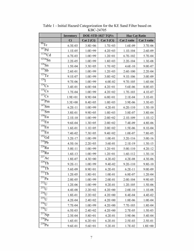
Table 1 - Initial Hazard Categorization for the KE Sand Filter based on KBC-24705
Inventory DOE-STD-1027 TQVs Haz Cat Ratio Ci Cat 2 (Ci) Cat 3 (Ci) Cat 2 ratio Cat 3 ratio
99Tc 6.3E-03 3.8E+06 1.7E+03 1.6E-09 3.7E-06 107Pd 1.1E-05 1.0E+99 4.2E+03 1.1E-104 2.6E-09 113mCd 6.7E-03 1.0E+99 1.2E+01 6.7E-102 5.7E-04 121mSn 2.2E-05 1.0E+99 1.8E+03 2.2E-104 1.3E-08 126Sn 1.5E-04 3.3E+05 1.7E+02 4.6E-10 9.0E-07 125Sb 2.6E-01 1.0E+99 1.2E+03 2.6E-100 2.2E-04 123Te 9.1E-07 1.0E+99 3.0E+02 9.1E-106 3.0E-09 129I 9.7E-06 1.0E+99 6.0E-02 9.7E-105 1.6E-04 134Cs 3.4E-01 6.0E+04 4.2E+01 5.6E-06 8.0E-03 135Cs 1.7E-04 1.0E+99 4.2E+02 1.7E-103 4.1E-07 137Cs 1.9E+01 8.9E+04 6.0E+01 2.1E-04 3.1E-01 147Pm 3.3E+00 8.4E+05 1.0E+03 3.9E-06 3.3E-03 147Sm 6.2E-11 1.0E+99 4.2E-01 6.2E-110 1.5E-10 151Sm 3.8E-01 9.9E+05 1.0E+03 3.8E-07 3.8E-04 150Eu 2.1E-10 1.0E+99 2.0E+02 2.1E-109 1.1E-12 152Eu 9.6E-04 1.3E+05 2.0E+02 7.4E-09 4.8E-06 154Eu 1.6E-01 1.1E+05 2.0E+02 1.5E-06 8.1E-04 155Eu 7.4E-02 7.3E+05 9.4E+02 1.0E-07 7.8E-05 152Gd 3.2E-17 1.0E+99 1.0E-01 3.2E-116 3.0E-16 210Pb 4.5E-16 2.2E+03 3.6E-01 2.1E-19 1.3E-15 226Ra 5.0E-11 1.0E+99 1.2E+01 5.0E-110 4.2E-12 228Ra 1.6E-13 1.0E+99 1.2E+01 1.6E-112 1.3E-14 227Ac 1.8E-07 4.3E+00 4.2E-02 4.2E-08 4.3E-06 229Th 9.2E-11 1.0E+99 9.4E-02 9.2E-110 9.8E-10 230Th 5.6E-09 8.9E+01 6.2E-01 6.2E-11 9.0E-09 232Th 1.2E-05 1.8E+01 1.0E-01 6.8E-07 1.2E-04 231Pa 2.0E-05 1.0E+99 2.0E-01 2.0E-104 9.9E-05 232U 1.2E-06 1.0E+99 8.2E-01 1.2E-105 1.5E-06 233U 4.4E-08 2.2E+02 4.2E+00 2.0E-10 1.1E-08 234U 1.8E-01 2.2E+02 4.2E+00 8.4E-04 4.4E-02 235U 4.2E-04 2.4E+02 4.2E+00 1.8E-06 1.0E-04 236U 7.7E-04 1.0E+99 4.2E+00 7.7E-103 1.8E-04 238U 6.5E-03 2.4E+02 4.2E+00 2.7E-05 1.5E-03 237Np 2.3E-04 5.8E+01 4.2E-01 3.9E-06 5.4E-04 238Pu 1.6E-01 6.2E+01 6.2E-01 2.5E-03 2.5E-01 239Pu 9.6E-01 5.6E+01 5.2E-01 1.7E-02 1.8E+00
7

Table 1 - Initial Hazard Categorization for the KE Sand Filter based on KBC-24705
Inventory DOE-STD-1027 TQVs Haz Cat Ratio Ci Cat 2 (Ci) Cat 3 (Ci) Cat 2 ratio Cat 3 ratio
240Pu 0.0E+00 5.6E+01 5.2E-01 0.0E+00 0.0E+00 241Pu 1.8E+01 2.9E+03 3.2E+01 6.3E-03 5.7E-01 242Pu 2.6E-05 5.9E+01 6.2E-01 4.3E-07 4.1E-05 244Pu 1.4E-13 1.0E+99 6.2E-01 1.4E-112 2.3E-13 241Am 1.0E+00 5.5E+01 5.2E-01 1.8E-02 1.9E+00 242mAm 3.8E-05 5.6E+01 5.2E-01 6.7E-07 7.3E-05 243Am 9.2E-06 5.5E+01 5.2E-01 1.7E-07 1.8E-05 242Cm 2.9E-02 1.7E+03 3.2E+01 1.7E-05 9.1E-04 243Cm 6.7E-02 1.0E+99 8.2E-01 6.7E-101 8.2E-02 244Cm 2.6E-01 1.0E+99 1.0E+00 2.6E-100 2.5E-01 245Cm 5.8E-09 5.3E+01 5.2E-01 1.1E-10 1.1E-08 246Cm 5.2E-11 1.0E+99 5.2E-01 5.2E-110 1.0E-10 247Cm 6.8E-18 1.0E+99 6.2E-01 6.8E-117 1.1E-17 248Cm 7.2E-19 1.0E+99 1.0E-01 7.2E-118 6.9E-18 Total 4.5E+01 4.5E-02 5.3E+00
4.2 Initial Hazard Categorization Results The initial hazard categorization results for the KE Basin sand filter using the isotopic data from KBC-24705, Rev. 0, indicates a HC-2 ratio of 0.045 and a HC-3 ratio of 5.3 as shown in Table 1.
4.3 Bounding Unmitigated Accident Selection The hazard analysis presented in Appendix B of SNF-22494 organizes hazardous conditions into accident groups. The final hazard categorization is determined based on the bounding unmitigated accident (i.e., scenario) for each accident group. Based on those results, both a seismic induced fire and a spray release while removing the sand filter media were chosen as the potential bounding accidents involving the sand filter.
4.4 Final Hazard Categorization Results
4.4.1 Accident Analysis: Seismic Induced Fire The seismic induced fire accident is assessed considering the progression of D&D activities that will take place at the KE Basin. Specifically, it is expected that the sand filter will be in service until the basin is dewatered. During D&D operations the sand filter is susceptible to damage from a seismically induced fire. In addition, during sand filter media removal, the filter media, including collected sludge, could be vulnerable. It is postulated that a seismically induced fire
8
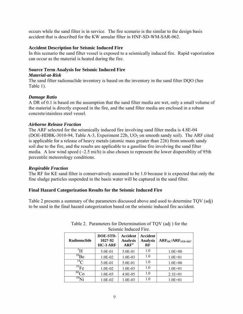
occurs while the sand filter is in service. The fire scenario is the similar to the design basis accident that is described for the KW annular filter in HNF-SD-WM-SAR-062. Accident Description for Seismic Induced Fire In this scenario the sand filter vessel is exposed to a seismically induced fire. Rapid vaporization can occur as the material is heated during the fire. Source Term Analysis for Seismic Induced Fire Material-at-Risk The sand filter radionuclide inventory is based on the inventory in the sand filter DQO (See Table 1). Damage Ratio A DR of 0.1 is based on the assumption that the sand filter media are wet, only a small volume of the material is directly exposed in the fire, and the sand filter media are enclosed in a robust concrete/stainless steel vessel. Airborne Release Fraction The ARF selected for the seismically induced fire involving sand filter media is 4.8E-04 (DOE-HDBK-3010-94, Table A-3, Experiment 22b, UO2 on smooth sandy soil). The ARF cited is applicable for a release of heavy metals (atomic mass greater than 226) from smooth sandy soil due to the fire, and the results are applicable to a gasoline fire involving the sand filter media. A low wind speed (~2.5 mi/h) is also chosen to represent the lower dispersiblity of 95th percentile meteorology conditions. Respirable Fraction The RF for KE sand filter is conservatively assumed to be 1.0 because it is expected that only the fine sludge particles suspended in the basin water will be captured in the sand filter. Final Hazard Categorization Results for the Seismic Induced Fire Table 2 presents a summary of the parameters discussed above and used to determine TQV (adj) to be used in the final hazard categorization based on the seismic induced fire accident.
Table 2. Parameters for Determination of TQV (adj ) for the Seismic Induced Fire.
Radionuclide DOE-STD-
1027-92 HC-3 ARF
Accident Analysis
ARFa
Accident Analysis
RF ARFHC/ARFSTD-1027
3H 5.0E-01 5.0E-01 1.0 1.0E+00 10Be 1.0E-02 1.0E-03 1.0 1.0E+01 14C 5.0E-01 5.0E-01 1.0 1.0E+00 55Fe 1.0E-02 1.0E-03 1.0 1.0E+01 60Co 1.0E-03 4.8E-05 1.0 2.1E+01 59Ni 1.0E-02 1.0E-03 1.0 1.0E+01
9

Table 2. Parameters for Determination of TQV (adj ) for the Seismic Induced Fire.
Radionuclide DOE-STD-
1027-92 HC-3 ARF
Accident Analysis
ARFa
Accident Analysis
RF ARFHC/ARFSTD-1027
63Ni 1.0E-02 1.0E-03 1.0 1.0E+01 79Se 1.0E-02 1.0E-03 1.0 1.0E+01 90Sr 1.0E-02 1.0E-03 1.0 1.0E+01 93Zr 1.0E-02 1.0E-03 1.0 1.0E+01
93Mo 1.0E-02 1.0E-03 1.0 1.0E+01 94Nb 1.0E-02 1.0E-03 1.0 1.0E+01 99Tc 1.0E-02 1.0E-03 1.0 1.0E+01 107Pd 1.0E-02 1.0E-03 1.0 1.0E+01
113mCd 1.0E-02 1.0E-03 1.0 1.0E+01 121mSn 1.0E-02 1.0E-03 1.0 1.0E+01 126Sn 1.0E-02 1.0E-03 1.0 1.0E+01 125Sb 1.0E-02 1.0E-03 1.0 1.0E+01 123Te 1.0E-02 1.0E-03 1.0 1.0E+01
129I 5.0E-01 5.0E-01 1.0 1.0E+00 134Cs 1.0E-02 1.0E-03 1.0 1.0E+01 135Cs 1.0E-02 1.0E-03 1.0 1.0E+01 137Cs 1.0E-02 1.0E-03 1.0 1.0E+01 147Pm 1.0E-02 1.0E-03 1.0 1.0E+01 147Sm 1.0E-02 1.0E-03 1.0 1.0E+01 151Sm 1.0E-02 1.0E-03 1.0 1.0E+01 150Eu 1.0E-02 1.0E-03 1.0 1.0E+01 152Eu 1.0E-02 1.0E-03 1.0 1.0E+01 154Eu 1.0E-02 1.0E-03 1.0 1.0E+01 155Eu 1.0E-02 1.0E-03 1.0 1.0E+01 152Gd 1.0E-02 1.0E-03 1.0 1.0E+01 210Pb 1.0E-02 1.0E-03 1.0 1.0E+01 226Ra 1.0E-03 4.8E-05 1.0 2.1E+01 228Ra 1.0E-03 4.8E-05 1.0 2.1E+01 227Ac 1.0E-03 4.8E-05 1.0 2.1E+01 229Th 1.0E-03 4.8E-05 1.0 2.1E+01 230Th 1.0E-03 4.8E-05 1.0 2.1E+01 232Th 1.0E-03 4.8E-05 1.0 2.1E+01 231Pa 1.0E-03 4.8E-05 1.0 2.1E+01 232U 1.0E-03 4.8E-05 1.0 2.1E+01 233U 1.0E-03 4.8E-05 1.0 2.1E+01 234U 1.0E-03 4.8E-05 1.0 2.1E+01 235U 1.0E-03 4.8E-05 1.0 2.1E+01 236U 1.0E-03 4.8E-05 1.0 2.1E+01 238U 1.0E-03 4.8E-05 1.0 2.1E+01
237Np 1.0E-03 4.8E-05 1.0 2.1E+01
10

Table 2. Parameters for Determination of TQV (adj ) for the Seismic Induced Fire.
Radionuclide DOE-STD-
1027-92 HC-3 ARF
Accident Analysis
ARFa
Accident Analysis
RF ARFHC/ARFSTD-1027
238Pu 1.0E-03 4.8E-05 1.0 2.1E+01 239Pu 1.0E-03 4.8E-05 1.0 2.1E+01 240Pu 1.0E-03 4.8E-05 1.0 2.1E+01 241Pu 1.0E-03 4.8E-05 1.0 2.1E+01 242Pu 1.0E-03 4.8E-05 1.0 2.1E+01 244Pu 1.0E-03 4.8E-05 1.0 2.1E+01
241Am 1.0E-03 4.8E-05 1.0 2.1E+01 242mAm 1.0E-03 4.8E-05 1.0 2.1E+01 243Am 1.0E-03 4.8E-05 1.0 2.1E+01 242Cm 1.0E-03 4.8E-05 1.0 2.1E+01 243Cm 1.0E-03 4.8E-05 1.0 2.1E+01 244Cm 1.0E-03 4.8E-05 1.0 2.1E+01 245Cm 1.0E-03 4.8E-05 1.0 2.1E+01 246Cm 1.0E-03 4.8E-05 1.0 2.1E+01 247Cm 1.0E-03 4.8E-05 1.0 2.1E+01 248Cm 1.0E-03 4.8E-05 1.0 2.1E+01
a – The ARF adjustment ratio includes a Damage Ratio (DR) of 0.1.
Table 3. Hazard Categorization Based on the Seismic Induced Fire.
Radionuclide
DOE-STD-
1027-92 HC-3 TQVs (Ci)
KE Sand Filter
Inventory(Ci)
Initial Hazard Categorization for KE Sand
Filter Material
Adjusted HC-3 TQV (ARF Ratio)
Adjusted HC-3 Ratio
(ARF Adjustment)
3H 1.60E+04 6.9E-02 4.3E-06 1.6E+04 4.3E-06 10Be 1.04E+02 6.8E-10 6.5E-12 1.0E+03 6.5E-13 14C 4.20E+02 2.7E-08 6.5E-11 4.2E+02 6.5E-11 55Fe 5.40E+03 1.6E-02 3.0E-06 5.4E+04 3.0E-07 60Co 2.80E+02 1.5E-01 5.2E-04 5.8E+03 2.5E-05 59Ni 1.18E+04 4.4E-03 3.7E-07 1.2E+05 3.7E-08 63Ni 5.40E+03 3.8E-03 7.1E-07 5.4E+04 7.1E-08 79Se 3.60E+02 1.0E-04 2.8E-07 3.6E+03 2.8E-08 90Sr 1.60E+01 6.5E-01 4.1E-02 1.6E+02 4.1E-03 93Zr 6.20E+01 6.7E-04 1.1E-05 6.2E+02 1.1E-06 93Mo 2.00E+03 9.2E-04 4.6E-07 2.0E+04 4.6E-08 94Nb 2.00E+03 1.5E-06 7.4E-10 2.0E+04 7.4E-11 99Tc 1.70E+03 6.3E-03 3.7E-06 1.7E+04 3.7E-07
11
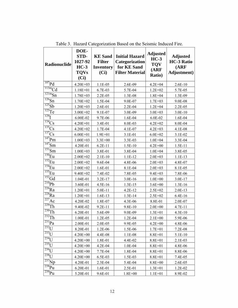
Table 3. Hazard Categorization Based on the Seismic Induced Fire.
Radionuclide
DOE-STD-
1027-92 HC-3 TQVs (Ci)
KE Sand Filter
Inventory(Ci)
Initial Hazard Categorization for KE Sand
Filter Material
Adjusted HC-3 TQV (ARF Ratio)
Adjusted HC-3 Ratio
(ARF Adjustment)
107Pd 4.20E+03 1.1E-05 2.6E-09 4.2E+04 2.6E-10 113mCd 1.18E+01 6.7E-03 5.7E-04 1.2E+02 5.7E-05 121mSn 1.78E+03 2.2E-05 1.3E-08 1.8E+04 1.3E-09 126Sn 1.70E+02 1.5E-04 9.0E-07 1.7E+03 9.0E-08 125Sb 1.20E+03 2.6E-01 2.2E-04 1.2E+04 2.2E-05 123Te 3.00E+02 9.1E-07 3.0E-09 3.0E+03 3.0E-10 129I 6.00E-02 9.7E-06 1.6E-04 6.0E-02 1.6E-04 134Cs 4.20E+01 3.4E-01 8.0E-03 4.2E+02 8.0E-04 135Cs 4.20E+02 1.7E-04 4.1E-07 4.2E+03 4.1E-08 137Cs 6.00E+01 1.9E+01 3.1E-01 6.0E+02 3.1E-02 147Pm 1.00E+03 3.3E+00 3.3E-03 1.0E+04 3.3E-04 147Sm 4.20E-01 6.2E-11 1.5E-10 4.2E+00 1.5E-11 151Sm 1.00E+03 3.8E-01 3.8E-04 1.0E+04 3.8E-05 150Eu 2.00E+02 2.1E-10 1.1E-12 2.0E+03 1.1E-13 152Eu 2.00E+02 9.6E-04 4.8E-06 2.0E+03 4.8E-07 154Eu 2.00E+02 1.6E-01 8.1E-04 2.0E+03 8.1E-05 155Eu 9.40E+02 7.4E-02 7.8E-05 9.4E+03 7.8E-06 152Gd 1.04E-01 3.2E-17 3.0E-16 1.0E+00 3.0E-17 210Pb 3.60E-01 4.5E-16 1.3E-15 3.6E+00 1.3E-16 226Ra 1.20E+01 5.0E-11 4.2E-12 2.5E+02 2.0E-13 228Ra 1.20E+01 1.6E-13 1.3E-14 2.5E+02 6.4E-16 227Ac 4.20E-02 1.8E-07 4.3E-06 8.8E-01 2.0E-07 229Th 9.40E-02 9.2E-11 9.8E-10 2.0E+00 4.7E-11 230Th 6.20E-01 5.6E-09 9.0E-09 1.3E+01 4.3E-10 232Th 1.00E-01 1.2E-05 1.2E-04 2.1E+00 5.9E-06 231Pa 2.00E-01 2.0E-05 9.9E-05 4.2E+00 4.8E-06 232U 8.20E-01 1.2E-06 1.5E-06 1.7E+01 7.2E-08 233U 4.20E+00 4.4E-08 1.1E-08 8.8E+01 5.1E-10 234U 4.20E+00 1.8E-01 4.4E-02 8.8E+01 2.1E-03 235U 4.20E+00 4.2E-04 1.0E-04 8.8E+01 4.8E-06 236U 4.20E+00 7.7E-04 1.8E-04 8.8E+01 8.8E-06 238U 4.20E+00 6.5E-03 1.5E-03 8.8E+01 7.4E-05 237Np 4.20E-01 2.3E-04 5.4E-04 8.8E+00 2.6E-05 238Pu 6.20E-01 1.6E-01 2.5E-01 1.3E+01 1.2E-02 239Pu 5.20E-01 9.6E-01 1.8E+00 1.1E+01 8.9E-02
12
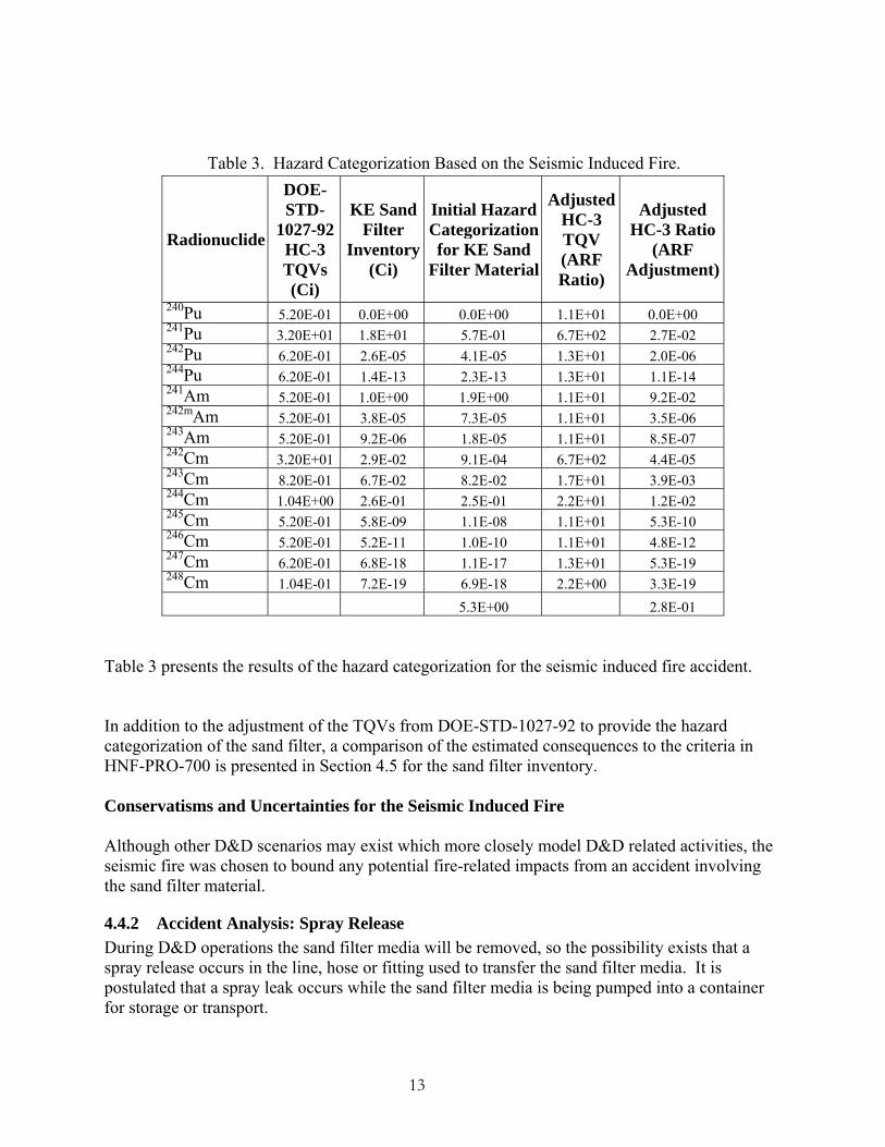
Table 3. Hazard Categorization Based on the Seismic Induced Fire.
Radionuclide
DOE-STD-
1027-92 HC-3 TQVs (Ci)
KE Sand Filter
Inventory(Ci)
Initial Hazard Categorization for KE Sand
Filter Material
Adjusted HC-3 TQV (ARF Ratio)
Adjusted HC-3 Ratio
(ARF Adjustment)
240Pu 5.20E-01 0.0E+00 0.0E+00 1.1E+01 0.0E+00 241Pu 3.20E+01 1.8E+01 5.7E-01 6.7E+02 2.7E-02 242Pu 6.20E-01 2.6E-05 4.1E-05 1.3E+01 2.0E-06 244Pu 6.20E-01 1.4E-13 2.3E-13 1.3E+01 1.1E-14 241Am 5.20E-01 1.0E+00 1.9E+00 1.1E+01 9.2E-02 242mAm 5.20E-01 3.8E-05 7.3E-05 1.1E+01 3.5E-06 243Am 5.20E-01 9.2E-06 1.8E-05 1.1E+01 8.5E-07 242Cm 3.20E+01 2.9E-02 9.1E-04 6.7E+02 4.4E-05 243Cm 8.20E-01 6.7E-02 8.2E-02 1.7E+01 3.9E-03 244Cm 1.04E+00 2.6E-01 2.5E-01 2.2E+01 1.2E-02 245Cm 5.20E-01 5.8E-09 1.1E-08 1.1E+01 5.3E-10 246Cm 5.20E-01 5.2E-11 1.0E-10 1.1E+01 4.8E-12 247Cm 6.20E-01 6.8E-18 1.1E-17 1.3E+01 5.3E-19 248Cm 1.04E-01 7.2E-19 6.9E-18 2.2E+00 3.3E-19 5.3E+00 2.8E-01
Table 3 presents the results of the hazard categorization for the seismic induced fire accident. In addition to the adjustment of the TQVs from DOE-STD-1027-92 to provide the hazard categorization of the sand filter, a comparison of the estimated consequences to the criteria in HNF-PRO-700 is presented in Section 4.5 for the sand filter inventory. Conservatisms and Uncertainties for the Seismic Induced Fire Although other D&D scenarios may exist which more closely model D&D related activities, the seismic fire was chosen to bound any potential fire-related impacts from an accident involving the sand filter material.
4.4.2 Accident Analysis: Spray Release During D&D operations the sand filter media will be removed, so the possibility exists that a spray release occurs in the line, hose or fitting used to transfer the sand filter media. It is postulated that a spray leak occurs while the sand filter media is being pumped into a container for storage or transport.
13
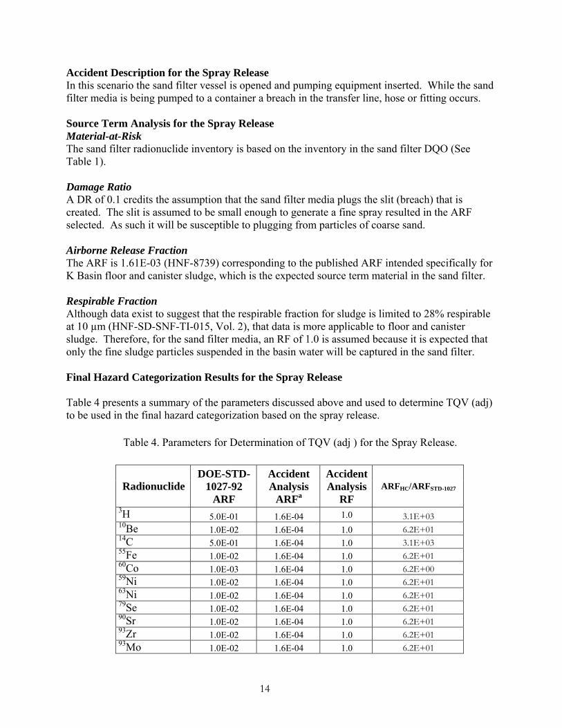
Accident Description for the Spray Release In this scenario the sand filter vessel is opened and pumping equipment inserted. While the sand filter media is being pumped to a container a breach in the transfer line, hose or fitting occurs. Source Term Analysis for the Spray Release Material-at-Risk The sand filter radionuclide inventory is based on the inventory in the sand filter DQO (See Table 1). Damage Ratio A DR of 0.1 credits the assumption that the sand filter media plugs the slit (breach) that is created. The slit is assumed to be small enough to generate a fine spray resulted in the ARF selected. As such it will be susceptible to plugging from particles of coarse sand. Airborne Release Fraction The ARF is 1.61E-03 (HNF-8739) corresponding to the published ARF intended specifically for K Basin floor and canister sludge, which is the expected source term material in the sand filter. Respirable Fraction Although data exist to suggest that the respirable fraction for sludge is limited to 28% respirable at 10 µm (HNF-SD-SNF-TI-015, Vol. 2), that data is more applicable to floor and canister sludge. Therefore, for the sand filter media, an RF of 1.0 is assumed because it is expected that only the fine sludge particles suspended in the basin water will be captured in the sand filter. Final Hazard Categorization Results for the Spray Release Table 4 presents a summary of the parameters discussed above and used to determine TQV (adj) to be used in the final hazard categorization based on the spray release.
Table 4. Parameters for Determination of TQV (adj ) for the Spray Release.
Radionuclide DOE-STD-
1027-92 ARF
Accident Analysis
ARFa
Accident Analysis
RF ARFHC/ARFSTD-1027
3H 5.0E-01 1.6E-04 1.0 3.1E+03 10Be 1.0E-02 1.6E-04 1.0 6.2E+01 14C 5.0E-01 1.6E-04 1.0 3.1E+03 55Fe 1.0E-02 1.6E-04 1.0 6.2E+01 60Co 1.0E-03 1.6E-04 1.0 6.2E+00 59Ni 1.0E-02 1.6E-04 1.0 6.2E+01 63Ni 1.0E-02 1.6E-04 1.0 6.2E+01 79Se 1.0E-02 1.6E-04 1.0 6.2E+01 90Sr 1.0E-02 1.6E-04 1.0 6.2E+01 93Zr 1.0E-02 1.6E-04 1.0 6.2E+01 93Mo 1.0E-02 1.6E-04 1.0 6.2E+01
14
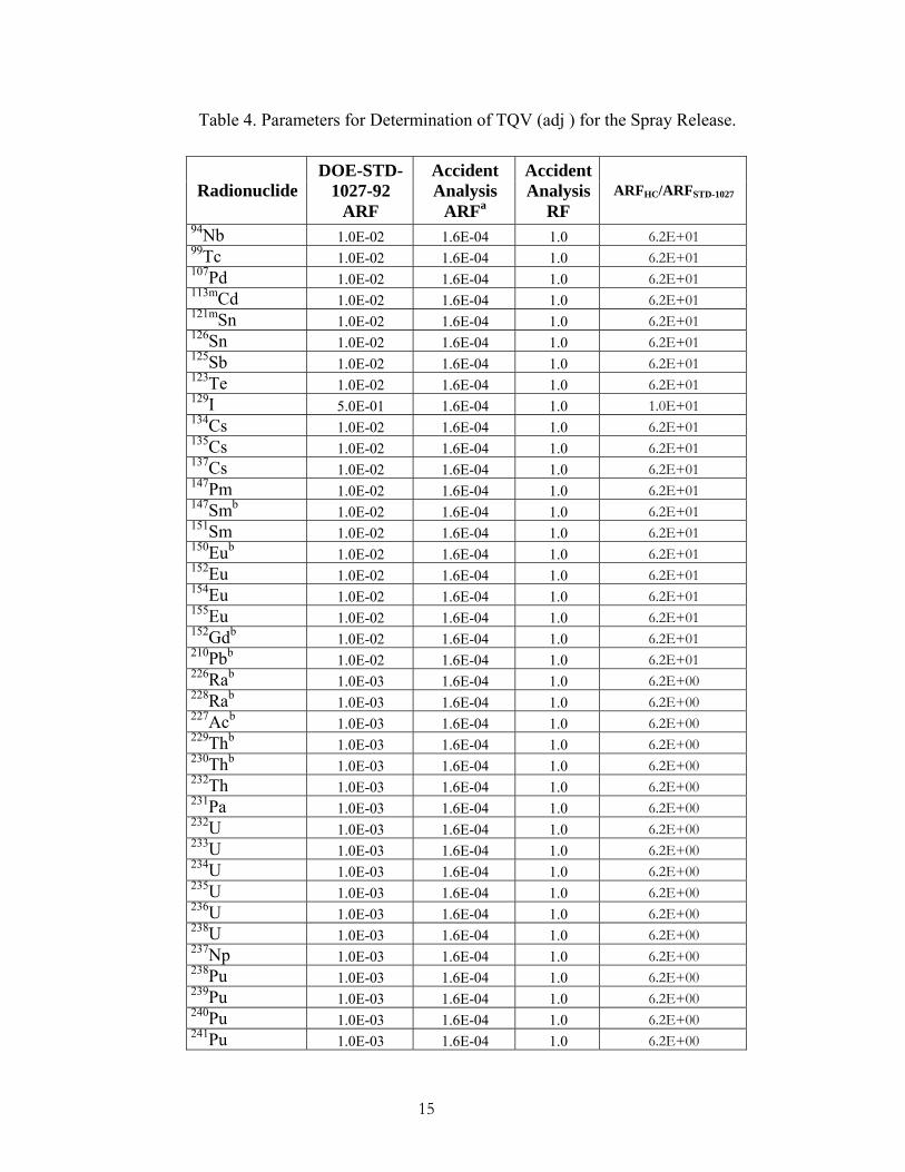
Table 4. Parameters for Determination of TQV (adj ) for the Spray Release.
Radionuclide DOE-STD-
1027-92 ARF
Accident Analysis
ARFa
Accident Analysis
RF ARFHC/ARFSTD-1027
94Nb 1.0E-02 1.6E-04 1.0 6.2E+01 99Tc 1.0E-02 1.6E-04 1.0 6.2E+01 107Pd 1.0E-02 1.6E-04 1.0 6.2E+01 113mCd 1.0E-02 1.6E-04 1.0 6.2E+01 121mSn 1.0E-02 1.6E-04 1.0 6.2E+01 126Sn 1.0E-02 1.6E-04 1.0 6.2E+01 125Sb 1.0E-02 1.6E-04 1.0 6.2E+01 123Te 1.0E-02 1.6E-04 1.0 6.2E+01 129I 5.0E-01 1.6E-04 1.0 1.0E+01 134Cs 1.0E-02 1.6E-04 1.0 6.2E+01 135Cs 1.0E-02 1.6E-04 1.0 6.2E+01 137Cs 1.0E-02 1.6E-04 1.0 6.2E+01 147Pm 1.0E-02 1.6E-04 1.0 6.2E+01 147Smb 1.0E-02 1.6E-04 1.0 6.2E+01 151Sm 1.0E-02 1.6E-04 1.0 6.2E+01 150Eub 1.0E-02 1.6E-04 1.0 6.2E+01 152Eu 1.0E-02 1.6E-04 1.0 6.2E+01 154Eu 1.0E-02 1.6E-04 1.0 6.2E+01 155Eu 1.0E-02 1.6E-04 1.0 6.2E+01 152Gdb 1.0E-02 1.6E-04 1.0 6.2E+01 210Pbb 1.0E-02 1.6E-04 1.0 6.2E+01 226Rab 1.0E-03 1.6E-04 1.0 6.2E+00 228Rab 1.0E-03 1.6E-04 1.0 6.2E+00 227Acb 1.0E-03 1.6E-04 1.0 6.2E+00 229Thb 1.0E-03 1.6E-04 1.0 6.2E+00 230Thb 1.0E-03 1.6E-04 1.0 6.2E+00 232Th 1.0E-03 1.6E-04 1.0 6.2E+00 231Pa 1.0E-03 1.6E-04 1.0 6.2E+00 232U 1.0E-03 1.6E-04 1.0 6.2E+00 233U 1.0E-03 1.6E-04 1.0 6.2E+00 234U 1.0E-03 1.6E-04 1.0 6.2E+00 235U 1.0E-03 1.6E-04 1.0 6.2E+00 236U 1.0E-03 1.6E-04 1.0 6.2E+00 238U 1.0E-03 1.6E-04 1.0 6.2E+00 237Np 1.0E-03 1.6E-04 1.0 6.2E+00 238Pu 1.0E-03 1.6E-04 1.0 6.2E+00 239Pu 1.0E-03 1.6E-04 1.0 6.2E+00 240Pu 1.0E-03 1.6E-04 1.0 6.2E+00 241Pu 1.0E-03 1.6E-04 1.0 6.2E+00
15

Table 4. Parameters for Determination of TQV (adj ) for the Spray Release.
Radionuclide DOE-STD-
1027-92 ARF
Accident Analysis
ARFa
Accident Analysis
RF ARFHC/ARFSTD-1027
242Pu 1.0E-03 1.6E-04 1.0 6.2E+00 244Pu 1.0E-03 1.6E-04 1.0 6.2E+00 241Am 1.0E-03 1.6E-04 1.0 6.2E+00 242mAm 1.0E-03 1.6E-04 1.0 6.2E+00 243Am 1.0E-03 1.6E-04 1.0 6.2E+00 242Cm 1.0E-03 1.6E-04 1.0 6.2E+00 243Cm 1.0E-03 1.6E-04 1.0 6.2E+00 244Cm 1.0E-03 1.6E-04 1.0 6.2E+00 245Cm 1.0E-03 1.6E-04 1.0 6.2E+00 246Cm 1.0E-03 1.6E-04 1.0 6.2E+00 247Cm 1.0E-03 1.6E-04 1.0 6.2E+00 248Cm 1.0E-03 1.6E-04 1.0 6.2E+00 a – The ARF adjustment ratio includes a Damage Ratio (DR) of 0.1.
Table 5, presents the results of the hazard categorization for the spray release.
Table 5. Hazard Categorization Based on the Spray Release.
Radionuclide
DOE-STD-1027-
92 HC-3 TQVs (Ci)
KE Sand Filter
Inventory(Ci)
Initial Hazard Categorization for KE Sand
Filter Material
Adjusted HC-3 TQV (ARF Ratio)
Adjusted HC-3 Ratio
(ARF Adjustment)
3H 1.6E+04 6.9E-02 4.3E-06 1.6E+05 1.4E-09 10Be 1.0E+02 6.8E-10 6.5E-12 6.5E+03 1.1E-13 14C 4.2E+02 2.7E-08 6.5E-11 4.2E+03 2.1E-14 55Fe 5.4E+03 1.6E-02 3.0E-06 3.4E+05 4.9E-08 60Co 2.8E+02 1.5E-01 5.2E-04 1.7E+03 8.4E-05 59Ni 1.2E+04 4.4E-03 3.7E-07 7.3E+05 6.0E-09 63Ni 5.4E+03 3.8E-03 7.1E-07 3.4E+05 1.1E-08 79Se 3.6E+02 1.0E-04 2.8E-07 2.2E+04 4.6E-09 90Sr 1.6E+01 6.5E-01 4.1E-02 9.9E+02 6.6E-04 93Zr 6.2E+01 6.7E-04 1.1E-05 3.9E+03 1.7E-07 93Mo 2.0E+03 9.2E-04 4.6E-07 1.2E+05 7.4E-09 94Nb 2.0E+03 1.5E-06 7.4E-10 1.2E+05 1.2E-11 99Tc 1.7E+03 6.3E-03 3.7E-06 1.1E+05 5.9E-08 107Pd 4.2E+03 1.1E-05 2.6E-09 2.6E+05 4.3E-11 113mCd 1.2E+01 6.7E-03 5.7E-04 7.3E+02 9.1E-06
16

Table 5. Hazard Categorization Based on the Spray Release.
Radionuclide
DOE-STD-1027-
92 HC-3 TQVs (Ci)
KE Sand Filter
Inventory(Ci)
Initial Hazard Categorization for KE Sand
Filter Material
Adjusted HC-3 TQV (ARF Ratio)
Adjusted HC-3 Ratio
(ARF Adjustment)
121mSn 1.8E+03 2.2E-05 1.3E-08 5.0E+07 2.0E-10 126Sn 1.7E+02 1.5E-04 9.0E-07 6.5E+03 1.4E-08 125Sb 1.2E+03 2.6E-01 2.2E-04 1.3E+06 3.5E-06 123Te 3.0E+02 9.1E-07 3.0E-09 3.4E+05 4.9E-11 129Ib 6.0E-02 9.7E-06 1.6E-04 1.7E+03 1.6E-05 134Cs 4.2E+01 3.4E-01 8.0E-03 7.3E+05 1.3E-04 135Cs 4.2E+02 1.7E-04 4.1E-07 3.4E+05 6.6E-09 137Cs 6.0E+01 1.9E+01 3.1E-01 2.2E+04 5.0E-03 147Pm 1.0E+03 3.3E+00 3.3E-03 9.9E+02 5.3E-05 147Sm 4.2E-01 6.2E-11 1.5E-10 3.9E+03 2.4E-12 151Sm 1.0E+03 3.8E-01 3.8E-04 1.2E+05 6.1E-06 150Eu 2.0E+02 2.1E-10 1.1E-12 1.2E+05 1.7E-14 152Eu 2.0E+02 9.6E-04 4.8E-06 1.1E+05 7.7E-08 154Eu 2.0E+02 1.6E-01 8.1E-04 2.6E+05 1.3E-05 155Eu 9.4E+02 7.4E-02 7.8E-05 7.3E+02 1.3E-06 152Gdb 1.0E-01 3.2E-17 3.0E-16 1.1E+05 4.9E-18 210Pbb 3.6E-01 4.5E-16 1.3E-15 1.1E+04 2.0E-17 226Rab 1.2E+01 5.0E-11 4.2E-12 7.5E+04 6.7E-13 228Rab 1.2E+01 1.6E-13 1.3E-14 1.9E+04 2.1E-15 227Acb 4.2E-02 1.8E-07 4.3E-06 6.0E-01 6.9E-07 229Thb 9.4E-02 9.2E-11 9.8E-10 2.6E+03 1.6E-10 230Thb 6.2E-01 5.6E-09 9.0E-09 2.6E+04 1.4E-09 232Th 1.0E-01 1.2E-05 1.2E-04 3.7E+03 2.0E-05 231Pa 2.0E-01 2.0E-05 9.9E-05 6.2E+04 1.6E-05 232U 8.2E-01 1.2E-06 1.5E-06 2.6E+01 2.4E-07 233U 4.2E+00 4.4E-08 1.1E-08 6.2E+04 1.7E-09 234U 4.2E+00 1.8E-01 4.4E-02 1.2E+04 7.1E-03 235U 4.2E+00 4.2E-04 1.0E-04 1.2E+04 1.6E-05 236U 4.2E+00 7.7E-04 1.8E-04 1.2E+04 3.0E-05 238U 4.2E+00 6.5E-03 1.5E-03 5.8E+04 2.5E-04 237Np 4.2E-01 2.3E-04 5.4E-04 6.5E+00 8.7E-05 238Pu 6.2E-01 1.6E-01 2.5E-01 2.2E+01 4.1E-02 239Pu 5.2E-01 9.6E-01 1.8E+00 7.5E+01 3.0E-01 240Pu 5.2E-01 0.0E+00 0.0E+00 7.5E+01 0.0E+00 241Pu 3.2E+01 1.8E+01 5.7E-01 2.6E-01 9.2E-02 242Pu 6.2E-01 2.6E-05 4.1E-05 5.8E-01 6.6E-06 244Pu 6.2E-01 1.4E-13 2.3E-13 3.9E+00 3.7E-14 241Am 5.2E-01 1.0E+00 1.9E+00 6.2E-01 3.1E-01
17

Table 5. Hazard Categorization Based on the Spray Release.
Radionuclide
DOE-STD-1027-
92 HC-3 TQVs (Ci)
KE Sand Filter
Inventory(Ci)
Initial Hazard Categorization for KE Sand
Filter Material
Adjusted HC-3 TQV (ARF Ratio)
Adjusted HC-3 Ratio
(ARF Adjustment)
242mAm 5.2E-01 3.8E-05 7.3E-05 1.2E+00 1.2E-05 243Am 5.2E-01 9.2E-06 1.8E-05 5.1E+00 2.9E-06 242Cm 3.2E+01 2.9E-02 9.1E-04 2.6E+01 1.5E-04 243Cm 8.2E-01 6.7E-02 8.2E-02 2.6E+01 1.3E-02 244Cm 1.0E+00 2.6E-01 2.5E-01 2.6E+01 4.0E-02 245Cmb 5.2E-01 5.8E-09 1.1E-08 2.6E+01 1.8E-09 246Cmb 5.2E-01 5.2E-11 1.0E-10 2.6E+01 1.6E-11 247Cmb 6.2E-01 6.8E-18 1.1E-17 2.6E+00 1.8E-18 248Cmb 1.0E-01 7.2E-19 6.9E-18 3.9E+00 1.1E-18 5.3E+00 8.1E-01
Conservatisms and Uncertainties for the Spray Release Although other D&D scenarios may exist which more closely model D&D related activities, the spray release was chosen to bound any potential impacts from an accident involving the transfer of sand filter material. The specific procedure for removing the sand filter media has not been finalized. However, it is assumed that spray release would bound the consequences of any method for the removal of the sand filter media.
4.5 Consequence Assessment
4.5.1 Analysis for the KE Basin Sand filter Seismic Induced Fire Accident Scenario Development and Description This accident is a seismically induced fire involving the KE Basin sand filter, which releases radioactive material to the air. The consequences of that accident scenario are estimated in this section. Two types of release mechanisms occur as a result of the fire: (1) initial release due to the fire and (2) resuspension of particles after the fire. Analysis Data and Assumptions The assumptions used to estimate the consequences from a release from the KE Basin sand filter are listed below.
18
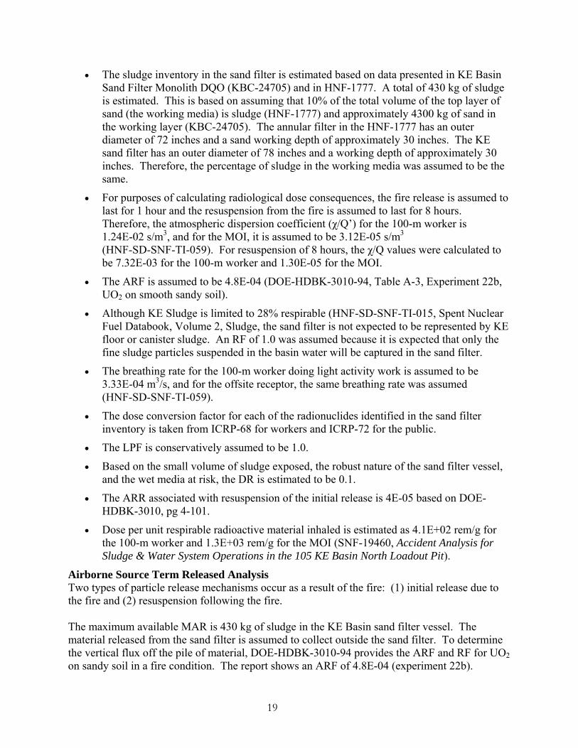
• The sludge inventory in the sand filter is estimated based on data presented in KE Basin Sand Filter Monolith DQO (KBC-24705) and in HNF-1777. A total of 430 kg of sludge is estimated. This is based on assuming that 10% of the total volume of the top layer of sand (the working media) is sludge (HNF-1777) and approximately 4300 kg of sand in the working layer (KBC-24705). The annular filter in the HNF-1777 has an outer diameter of 72 inches and a sand working depth of approximately 30 inches. The KE sand filter has an outer diameter of 78 inches and a working depth of approximately 30 inches. Therefore, the percentage of sludge in the working media was assumed to be the same.
• For purposes of calculating radiological dose consequences, the fire release is assumed to last for 1 hour and the resuspension from the fire is assumed to last for 8 hours. Therefore, the atmospheric dispersion coefficient (χ/Q’) for the 100-m worker is 1.24E-02 s/m3, and for the MOI, it is assumed to be 3.12E-05 s/m3 (HNF-SD-SNF-TI-059). For resuspension of 8 hours, the χ/Q values were calculated to be 7.32E-03 for the 100-m worker and 1.30E-05 for the MOI.
• The ARF is assumed to be 4.8E-04 (DOE-HDBK-3010-94, Table A-3, Experiment 22b, UO2 on smooth sandy soil).
• Although KE Sludge is limited to 28% respirable (HNF-SD-SNF-TI-015, Spent Nuclear Fuel Databook, Volume 2, Sludge, the sand filter is not expected to be represented by KE floor or canister sludge. An RF of 1.0 was assumed because it is expected that only the fine sludge particles suspended in the basin water will be captured in the sand filter.
• The breathing rate for the 100-m worker doing light activity work is assumed to be 3.33E-04 m3/s, and for the offsite receptor, the same breathing rate was assumed (HNF-SD-SNF-TI-059).
• The dose conversion factor for each of the radionuclides identified in the sand filter inventory is taken from ICRP-68 for workers and ICRP-72 for the public.
• The LPF is conservatively assumed to be 1.0.
• Based on the small volume of sludge exposed, the robust nature of the sand filter vessel, and the wet media at risk, the DR is estimated to be 0.1.
• The ARR associated with resuspension of the initial release is 4E-05 based on DOE-HDBK-3010, pg 4-101.
• Dose per unit respirable radioactive material inhaled is estimated as 4.1E+02 rem/g for the 100-m worker and 1.3E+03 rem/g for the MOI (SNF-19460, Accident Analysis for Sludge & Water System Operations in the 105 KE Basin North Loadout Pit).
Airborne Source Term Released Analysis Two types of particle release mechanisms occur as a result of the fire: (1) initial release due to the fire and (2) resuspension following the fire. The maximum available MAR is 430 kg of sludge in the KE Basin sand filter vessel. The material released from the sand filter is assumed to collect outside the sand filter. To determine the vertical flux off the pile of material, DOE-HDBK-3010-94 provides the ARF and RF for UO2 on sandy soil in a fire condition. The report shows an ARF of 4.8E-04 (experiment 22b).
19
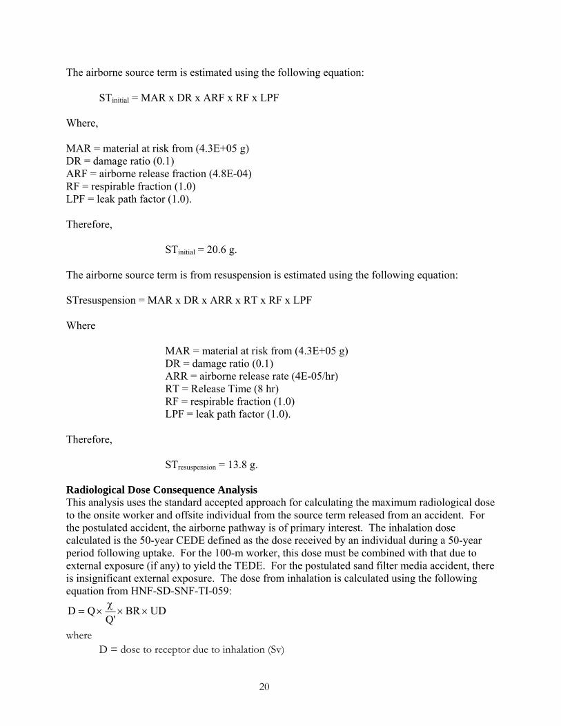
The airborne source term is estimated using the following equation: STinitial = MAR x DR x ARF x RF x LPF Where, MAR = material at risk from (4.3E+05 g) DR = damage ratio (0.1) ARF = airborne release fraction (4.8E-04) RF = respirable fraction (1.0) LPF = leak path factor (1.0). Therefore, STinitial = 20.6 g. The airborne source term is from resuspension is estimated using the following equation: STresuspension = MAR x DR x ARR x RT x RF x LPF Where
MAR = material at risk from (4.3E+05 g) DR = damage ratio (0.1) ARR = airborne release rate (4E-05/hr) RT = Release Time (8 hr) RF = respirable fraction (1.0) LPF = leak path factor (1.0).
Therefore,
STresuspension = 13.8 g. Radiological Dose Consequence Analysis This analysis uses the standard accepted approach for calculating the maximum radiological dose to the onsite worker and offsite individual from the source term released from an accident. For the postulated accident, the airborne pathway is of primary interest. The inhalation dose calculated is the 50-year CEDE defined as the dose received by an individual during a 50-year period following uptake. For the 100-m worker, this dose must be combined with that due to external exposure (if any) to yield the TEDE. For the postulated sand filter media accident, there is insignificant external exposure. The dose from inhalation is calculated using the following equation from HNF-SD-SNF-TI-059:
UDBR'Q
QD ××χ
×=
where D = dose to receptor due to inhalation (Sv)
20

Q = respirable source term (g)
'Qχ = atmospheric dispersion coefficient (s/m3)
BR = breathing rate (m3/s)
UD = inhalation unit dose (rem/g).
The atmospheric dispersion coefficient is the time-integrated normalized air concentration at the receptor. It represents the dilution of an airborne contaminant due to atmospheric mixing and turbulence. It is the ratio of the average contaminant air concentration at the receptor to the contaminant release rate at the release point. It is used to determine the dose consequences for a receptor based on the quantity released, atmospheric conditions, and the distance to the receptor of interest. The BR is the average volume of air an individual breathes in every second. The inhalation unit dose is the dose that the individual receives from inhalation of every unit of respirable source term. The unit dose is 4.10E+02 rem/g CEDE for the 100-m worker and 1.30E+03 for the MOI. The dose from inhalation for the initial release to the 100-m worker can be calculated as follows:
D = (20.6 g) x (1.24E-02 s/m3) x (3.33E-04 m3/s) x (4.10E+02 rem/g) = 0.03 rem . The dose from inhalation to the 100-m worker from resuspension is similarly calculated as follows: D = (13.8 g) x (7.32E-03 s/m3) x (3.33E-04 m3/s) x (4.10E+02 rem/g) = 0.01 rem. The total dose to the 100 meter worker is 0.03 rem + 0.01 rem = 4.0E-02 rem. Similarly, the dose to the maximally exposed offsite individual is calculated as 3.7E-04 rem. Analysis Conservatisms and Uncertainties for the Seismic Induced Fire The amount of sludge remaining in the sand filter is expected to be small since the sand filter is back flushed into the NLOP. Seismic Induced Fire Analysis Results and Conclusions The calculated CEDE to the 100-m worker is 4.0E-02 rem. The calculated CEDE received by the MOI (at approximately 10,000 m) is 3.7E-04 rem. The results of this accident are well below the 25 rem 100-m worker guidelines and 1 rem offsite receptor limits for Low consequences as defined by HNF-PRO-700.
4.5.2 Analysis for the KE Basin Sand filter Spray Release Accident Scenario Development and Description
21
The spray release accident was chosen to estimate the bounding consequences associated with removal of the sand filter media. The consequences of that accident scenario are estimated in this section. Two types of release mechanisms occur as a result of the spray release: (1) initial spray release and (2) resuspension of material after the spray. Analysis Data and Assumptions The assumptions used to estimate the consequences of a release from the KE Basin sand filter are listed below.
• The sludge inventory in the sand filter is estimated based on data presented in KE Basin Sand Filter Monolith DQO (KBC-24705) and in HNF-1777. A total of 430 kg of sludge is estimated. This is based on assuming that 10% of the total volume of the top layer of sand (the working media) is sludge (HNF-1777) and approximately 4300 kg of sand in the working layer (KBC-24705). The annular filter in the HNF-1777 has an outer diameter of 72 inches and a sand working depth of approximately 30 inches. The KE sand filter has an outer diameter of 78 inches and a working depth of approximately 30 inches. Therefore, the percentage of sludge in the working media was assumed to be the same.
• For purposes of calculating radiological dose consequences, the spray is assumed to last for less than 1 hour and resuspension is assumed to last for 8 hours. Therefore, for the spray release, the atmospheric dispersion coefficient (χ/Q’) for the 100-m worker is 7.32E-02 s/m3, and for the MOI, it is 4.49E-05 s/m3 (HNF-SD-SNF-TI-059). For the resuspension release, the atmospheric dispersion coefficient (χ/Q’) for the 100-m worker was calculated to be 7.321E-03 s/m3, and for the MOI, it is assumed to be 1.30E-05 s/m3 (HNF-SD-SNF-TI-059).
• The ARF is assumed to be 1.61E-03 (HNF-8739).
• Although KE Sludge is limited to 28% respirable (HNF-SD-SNF-TI-015, Spent Nuclear Fuel Databook, Volume 2, Sludge, the sand filter is not expected to be represented by KE floor or canister sludge. Therefore, an RF of 1.0 was assumed because it is expected that only the fine sludge particles suspended in the basin water will be captured in the sand filter.
• The ARR associated with resuspension of the initial release is 4E-05 based on DOE-HDBK-3010, pg 4-101. It is conservatively assumed that the initial spray release has dried.
• The average inhalation or BR for the 100-m worker doing light activity work is assumed to be 3.33E-04 m3/s, and for the offsite receptor, the same value is used (HNF-SD-SNF-TI-059).
• The DF for each of the radionuclides identified in the sand filter inventory is taken from ICRP-68 for workers and ICRP-72 for the public.
• The LPF is conservatively assumed to be 1.0.
• Based on the expected plugging of the spray leak with the sand filter media and the wet media at risk, the DR is estimated to be 0.1.
22
• Dose per unit respirable radioactive material inhaled is estimated as 4.1E+02 rem/g for the 100-m worker and 1.3E+03 rem/g for the MOI (SNF-19460, Accident Analysis for Sludge & Water System Operations in the 105 KE Basin North Loadout Pit).
Airborne Source Term Released Analysis Two types of particle release mechanisms occur as a result of the spray release: (1) initial release due to the spray and (2) resuspension following the spray. For the spray release, the resuspension release following the spray would be insignificant compared to the initial release. The airborne source term is estimated using the following equation: STinitial = MAR x DR x ARF x RF x LPF where
MAR = material at risk from (4.30E+02 kg) DR = damage ratio (0.1) ARF = airborne release fraction (1.61E-03) RF = respirable fraction (1.0) LPF = leak path factor (1.0).
Therefore,
STinitial = 6.9E+01 grams.
For resuspended material, the airborne source term is estimated using a slightly modified version of this equation as follows:
RTLPFRFARRDRMARQ ×××××= where
ARR = airborne release rate (/hr) RT = resuspension release time (hr)
The ARR is the coefficient used to estimate the rate at which the radioactive material is resuspended in air as a result of atmospheric conditions. The RT is the time period over which resuspension can occur. The airborne source term resulting from the resuspension of spray release is calculated below: STresuspension = (4.3E+05g) x 0.1 x 4E-05 x 1.0 x 1.0 x 8.0 STresuspension = 13.8 grams.
Radiological Dose Consequence Analysis This analysis uses the standard accepted approach for calculating the maximum radiological dose to the onsite worker and offsite individual from the source term released from an accident. For
23
the postulated accident, the airborne pathway is of primary interest. The inhalation dose calculated is the 50-year CEDE defined as the dose received by an individual during a 50-year period following uptake. For the 100-m worker, this dose must be combined with that due to external exposure (if any) to yield the TEDE. For the postulated sand filter media accident, there is insignificant external exposure. The dose from inhalation is calculated using the following equation from HNF-SD-SNF-TI-059:
UDBR'Q
QD ××χ
×=
where, D = dose to receptor due to inhalation (Sv) Q = respirable source term (g)
'Qχ
= atmospheric dispersion coefficient (s/m3) BR = breathing rate (m3/s) UD = inhalation unit dose (rem/g).
The atmospheric dispersion coefficient is the time-integrated normalized air concentration at the receptor. It represents the dilution of an airborne contaminant due to atmospheric mixing and turbulence. It is the ratio of the average contaminant air concentration at the receptor to the contaminant release rate at the release point. It is used to determine the dose consequences for a receptor based on the quantity released, atmospheric conditions, and the distance to the receptor of interest. The BR is the average volume of air an individual breathes in every second. The inhalation unit dose is the dose that the individual receives from inhalation of every unit of respirable source term. The unit dose is 4.10E+02 rem/g CEDE for the 100-m worker and 1.30E+03 for the MOI. The dose from inhalation due to the initial release to the 100-m worker can be calculated as follows:
)/0210.4()/0433.3()/0232.7()019.6( 33 gremEsmEmsEgED +×−×−×+=
. remE 019.6 −= The dose from inhalation due to the initial release to the MOI is similarly calculated as follows:
)/0330.1()/0433.3()/0549.4()019.6( 33 gremEsmEmsEgED +×−×−×+=
= 1.3 E-03 rem . The dose from inhalation to the 100-m worker due to the resuspension release can be calculated as follows:
)/0210.4()/0433.3()/0332.7()014.1( 33 gremEsmEmsEgED +×−×−×+=
. remE 020.1 −= The dose from inhalation to the MOI due to resuspension is similarly calculated as follows:
24
)/0330.1()/0433.3()/0530.1()014.1( 33 gremEsmEmsEgED +×−×−×+= = 7.8 E-05 rem .
The total dose to the 100-m onsite worker is:
6.9E-01 + 1.0E-02 = 7.0E-01 rem The total dose to the MOI is:
1.3E-03 + 7.8E-05 = 1.4E-03 rem Analysis Conservatisms and Uncertainties for the Spray Release Although other deactivation and decommissioning scenarios may exist which more closely model deactivation and decommissioning-related activities, the spray was chosen to bound any potential impacts from an accident involving the removal of the sand filter media. The equipment used to remove the sand filter media has not been determined. Further analysis may be warranted of the spray release when details on the method to remove the media are available. Spray Release Analysis Results and Conclusions The calculated CEDE to the 100-m worker is 0.7 rem. The calculated CEDE received by the MOI (at approximately 10,000 m) is 1.4E-03 rem. The results of this accident are below the 25 rem 100-m worker guidelines and 1 rem offsite receptor limits for Low consequences as defined by HNF-PRO-700.
25

5.0 Conclusions The KE sand filter radionuclide data contained in KE Basin Sand Filter Monolith DQO (KBC-24705) indicates an initial hazard categorization of HC-3. Considering the bounding accidents that can cause a release of the sand filter media, the KE Basin sand filter contribution to the hazard categorization ratio is 0.8. Considering other radioactive materials in the basin, the sand filter media would need to be removed to allow consideration of categorizing the KE Basin as less than hazard category 3 after fuel and sludge are removed. Further, the predicted consequences of the maximum credible unmitigated release from the sand filter do not to have any significant localized consequences according to the DOE-STD-1027-92 qualitative consequence criteria and fall in the Low category according to HNF-8739.
26

6.0 References 10 CFR 830, “Nuclear Safety Management,” Subpart B, “Safety Basis Requirements,”
Title 10, Code of Federal Regulations, Part 830, as amended.
DOE-ID Order 420.D, Requirements and Guidance for Safety Analysis, U.S. Department of Energy, Idaho Operations Office, July 2003.
DOE/EIS-0245, 1995, Environmental Impact Statement—Management of Spent Nuclear Fuel from the K Basins at the Hanford Site, U.S. Department of Energy, Richland Washington.
DOE-HDBK-3010-94, 1994, Airborne Release Fractions/Rates and Respirable Fractions for Nonreactor Nuclear Facilities, U.S. Department of Energy, Washington, D.C.
DOE-STD-1027-92, 1997, Hazard Categorization and Accident Analysis Techniques for Compliance with DOE Order 5480.23 Nuclear Safety Analysis Reports, Change Notice No. 1, U.S. Department of Energy, Washington, D.C.
HNF-1777, K West Basin IWTS Annular Filter Vessel Accident Calculations & Derivation of Leak Path Factors, Rev. 5, Fluor Hanford, Inc., Richland, Washington, January 2000.
HNF-8739, 2004, Hanford Safety Analysis and Risk Assessment Handbook (SARAH), Rev. 1, Fluor Hanford, Inc., Richland, Washington.
HNF-SD-SNF-TI-059, 1999, A Discussion on the Methodology for Calculating Radiological and Toxicological Consequences for the Spent Fuel Project at the Hanford Site, Rev. 0, Fluor Hanford, Inc., Richland, Washington.
HNF-SD-WM-SAR-062, 2004, K Basins Final Safety Analysis Report, Rev. 8-I, Fluor Hanford, Inc., Richland, Washington.
KBC-24705, KE Basin Sand Filter Monolith DQO, Rev. 0
LA-12981-MS, Table of DOE-STD-1027-92 Hazard Category 3 Threshold Quantities for the ICRP-30 List of 757 Radionuclides, LANL Fact Sheet for threshold quantities of any isotopes of interest, Los Alamos National Laboratories, Los Alamos, New Mexico.
NSTP 2002-2, 2002, Methodology for Final Hazard Categorization for Nuclear Facilities from Category 3 to Radiological, Department of Nuclear and Facility Safety Policy, Washington, D.C.
SNF-19460, 2004, Accident Analysis for Sludge & Water System Operations In The 105 KE Basin North Loadout Pit, Rev. 0, Fluor Hanford, Inc., Richland, Washington.
SNF-22494, 2005, Hazard Categorization Assessment for the K East Basin During Deactivation and Decommissioning Activities, Fluor Hanford, Inc., Richland, Washington.
27

28