keno-vi modeling of double heterogeneous reactor systems
TRANSCRIPT
ORNL is managed by UT-Battelle, LLC for the US Department of Energy
KENO-VI modeling of double heterogeneous reactor systems using TRISO fuel
Friederike Bostelmann, Cihangir Celik
Reactor and Nuclear Systems Division
Oak Ridge National Laboratory
2nd SCALE Users’ Group Workshop August 27–29, 2018, ORNL

2
Outline
• Introduction– What are double heterogeneous systems?– What are the challenges for modeling these systems?
• Modeling double-het systems with SCALE/KENO-VI
• SCALE hands-on: Part 1 (together)
• SCALE hands-on: Part 2 (alone)
• Other SCALE capabilities for double-het systems
• Outlook to SCALE 6.3

3
Outline
• Introduction– What are double heterogeneous systems?– What are the challenges for modeling these systems?
• Modeling double-het systems with SCALE/KENO-VI
• SCALE hands-on: Part 1 (together)
• SCALE hands-on: Part 2 (alone)
• Other SCALE capabilities for double-het systems
• Outlook to SCALE 6.3

4
Double heterogeneous systems
Figures: Courtesy of M. P. Baker, et al., J. Nucl. Materials 432, pp.395-406, 2013; X-Energy website
Tristructural (TRISO) fuel particle
(1) Fuel pebble

5
Double heterogeneous systems
(2) Prismatic fuel block with fuel compacts (3) Plate fuel
Figure: Courtesy of H. Gougar, NEAMS presentation, January 24, 2016.
Figures: D. H. Holcomb, et al., ORNL/TM-2011/365, September 2011.

6
Double heterogeneous systems• Renewed interest in advanced reactor systems:
– High temperature gas-cooled reactors (HTGRs); pebbles, prismatic blocks– Fluoride salt-cooled high-temperature reactors (FHRs); pebbles, plates, etc.– Other designs
• Characteristics: TRISO fuel, graphite moderator, helium or molten salt cooled
Figures: Courtesy of J. Powers, PhD Thesis, University of California, Berkeley, 2011. Figure: G. Strydom, F. Bostelmann, INL/EXT-15-34868, Rev. 1, September 2015.
TRISO particle
Look insight pebble-bed reactor Prismatic HTGR design

7
Outline
• Introduction– What are double heterogeneous systems?– What are the challenges for modeling these systems?
• Modeling double-het systems with SCALE/KENO-VI
• SCALE hands-on: Part 1 (together)
• SCALE hands-on: Part 2 (alone)
• Other SCALE capabilities for double-het systems
• Outlook to SCALE 6.3

8
Modeling challenges of double-het systems
• TRISO particles are randomly dispersed in a graphite matrix
• Criticality calculations:– Using continuous-energy (CE) cross section dataWe can model everything explicitly
– Using multigroup (MG) cross section data Problem-independent MG cross sections must be shielded

9
Modeling challenges of double-het systems
• Continuous-energy calculations:
a) Simplify TRISO particles distributed in array• Relatively easy to model• Allows for neutron streaming paths• Particle clipping recommended to be avoided (adds another
unrealistic element and fuel mass might be incorrect)• Particles closer together to keep overall packing fraction
correct larger local packing fraction• Some codes: on-the-fly random placement of the TRISO
particle within its lattice cell
Infinite particle lattice
Lattice without clipping
High temperature reactor (HTR) fuel pebble models
for CE calculations

10
Modeling challenges of double-het systems
• Continuous-energy calculations:
b) Define every single randomly picked position of TRISO particles in fuel region
• A larger modeling effort is required• Code might have issues determining initial neutron
distribution some effort has to be spent on defining source
• An extremely long computation time is required, depending on the number of particles
• This model is closer to reality, but it still has simplification (cf. particle packing fraction is different in outer zone of fuel pebble)
CE HTR fuel pebble model with randomly
dispersed particles

11
Modeling challenges of double-het systems
• Multigroup calculations:
– Generic MG cross sections must be corrected for self-shielding effects in a given application:1. TRISO particle in graphite matrix, embedded in fuel
pebble/rod/plate2. Fuel component in lattice
– MG calculations allow for simple modeling and fast computation time
– However, approximation is used, so it always must be validated
Double-het mix
MG HTR fuel pebble model

12
Modeling challenges of double-het systems
• Self-shielding:Impact of resonance absorption on neutron spectrum
1e+00
1e+01
1e+02
1e+03
1e+04
1e+05
Average Group Cross-
section =σ(ba
rns)
Φ(E)σ(E)
σg = 3 b
Γt(E-E0)/( /2)
Undiluted absorber (pure absorber)
13
Outline
• Introduction– What are double heterogeneous systems?– What are the challenges for modeling these systems?
• Modeling double-het systems with SCALE/KENO-VI• SCALE hands-on: Part 1 (together)
• SCALE hands-on: Part 2 (alone)
• Other SCALE capabilities for double-het systems
• Outlook to SCALE 6.3
14
Modeling double-het systems with SCALE
• Criticality calculations with the 3D Monte Carlo code KENO-VI using either CE or MG data
• KENO-VI is used via the CSAS6 sequence that automates the cross section processing

15
CSAS6 criticality safety sequence
CE mode MG mode
SCALE driver and CSAS6
Input
KENO-VI
END
SCALE driver and CSAS6
Input
KENO-VI
END
XSProc
Monte Carlo criticality calculation
Cross section preparation, including self-shielding calculation
16
CSAS6 criticality safety sequence
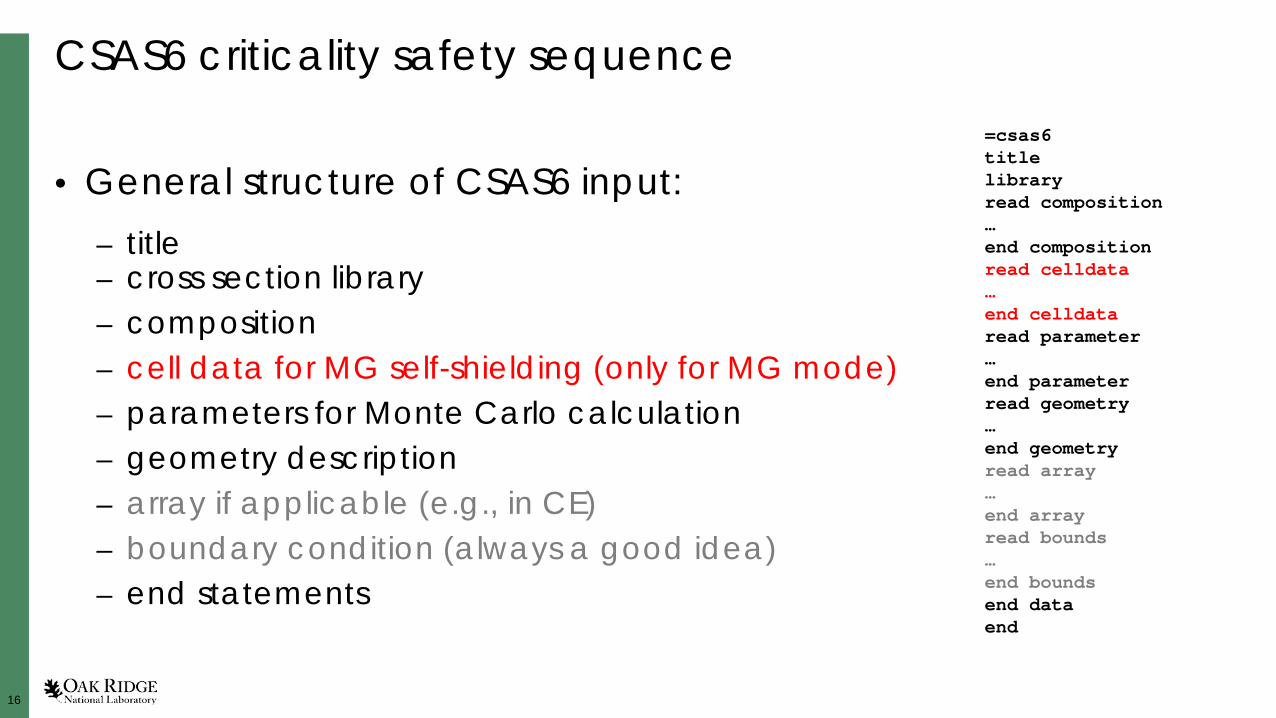
• General structure of CSAS6 input:– title– cross section library– composition– cell data for MG self-shielding (only for MG mode)– parameters for Monte Carlo calculation– geometry description– array if applicable (e.g., in CE)– boundary condition (always a good idea)– end statements
=csas6titlelibraryread composition…end compositionread celldata…end celldataread parameter…end parameterread geometry…end geometryread array…end arrayread bounds…end boundsend dataend

17
SCALE cross section libraries
• Continuous-energy: – ENDF/B-VII.0 (ce_v7.0_endf)– ENDF/B-VII.1 (ce_v7.1_endf)
• Multigroup: – ENDF/B-VII.0: 238-group (v7-238)– ENDF/B-VII.1: 56g, 252g (v7.1-56, v7.1-252)
Use of ENDF/B-VII.1 data is strongly recommended!The difference in neutron capture in carbon between the two ENDF libraries can lead to significant eigenvalue differences (>1,000 pcm) in graphite-moderated systems

18
CSAS6 criticality safety sequence: composition
• There are different ways to define composition via standard composition, atom percent compositions, solutions, etc. Fulcrum’s autocompletion can be used for assistance
• Here is one example: entering nuclide-wise number densities (atoms/barn-cm):
h 1 0 0.0667531 300.0 endpu-238 2 0 4.747e-07 293.0 endpu-239 2 0 1.068e-04 293.0 endpu-240 2 0 1.577e-05 293.0 endpu-241 2 0 5.626e-06 293.0 endpu-242 2 0 6.187e-07 293.0 endrh-103 2 0 1.104e-05 293.0 end
Nuclide #mix 0 nuclide_density temperature end

19
CSAS6 criticality safety sequence: parameter
• KENO-VI parameters:– numbers of particles per generation (npg)– number of total generations (gen)– number of inactive generations (nsk)– optional: desired eigenvalue uncertainty, random number, doppler
broadening rejection correction (DBRC), energy group structure for output when using CE mode, etc.
• Ensure fission source convergence: check convergence tests of Shannon entropy in output file
• Remember statistical uncertainty ~ 1/√N

20
KENO-VI geometry
• Volumes are built in sections called units.Each unit is independent of all other units and has its own coordinate system
• Units are built using regions. Regions are made using the KENO-VI geometry shapes. The unit boundary must fully enclose all defined regions in the unit
• Regions may share boundaries, may intersect, and may be rotated
Regions in a unit Shared boundaries
Intersecting regions
Rotated cylinder

21
KENO-VI geometry (continued)
• A hole is used to place a unit within a region of a different unit. The hole must be completely contained within the region and may not intersect other holes or nested arrays
• An array is an ordered stack of units. The touching faces of adjacent units in an array must be the same size
• A global unit that encloses the entire system must be specified. All geometry data used in a problem are correlated by the global unit coordinate system
Unit containingHOLES
Array of units

22
KENO-VI array types
Dodecahedral
Hexagonal (or triangular)
Standard hex
Rotated hex
Rectangular

23
KENO-VI input records• Three types of records are used to define the volume, position,
and material contents of the regions in a unit1. Geometry records2. Contents records3. Boundary records
unit 100sphere 1 0.0250sphere 2 0.0340sphere 3 0.0380sphere 4 0.0415sphere 5 0.0455cuboid 6 6p0.097634150media 100 1 1media 101 1 2 -1media 102 1 3 -2media 103 1 4 -3media 104 1 5 -4media 105 1 6 -5boundary 6

24
KENO-VI input records• Three types of records are used to define the volume, position,
and material contents of the regions in a unit1. Geometry records2. Contents records3. Boundary records
• Geometry keyword
• Geometry record label
• Geometry boundary definitions
• Geometry modification data
unit 100sphere 1 0.0250sphere 2 0.0340sphere 3 0.0380sphere 4 0.0415sphere 5 0.0455cuboid 6 6p0.097634150media 100 1 1media 101 1 2 -1media 102 1 3 -2media 103 1 4 -3media 104 1 5 -4media 105 1 6 -5boundary 6

25
KENO-VI input records• Three types of records are used to define the volume, position,
and material contents of the regions in a unit1. Geometry records2. Contents records3. Boundary records
• Contents keyword (array, hole, media)
• ID number (array #, unit #, mixture #)
• Bias ID number (media only)
• Region definition vector (array, media)
unit 100sphere 1 0.0250sphere 2 0.0340sphere 3 0.0380sphere 4 0.0415sphere 5 0.0455cuboid 6 6p0.097634150media 100 1 1media 101 1 2 -1media 102 1 3 -2media 103 1 4 -3media 104 1 5 -4media 105 1 6 -5boundary 6

26
KENO-VI input records• Three types of records are used to define the volume, position,
and material contents of the regions in a unit1. Geometry records2. Contents records3. Boundary records
Specify the overall volume of a unit:• One and only one boundary record is required for
each unit• Only the volume defined in the region definition
vector of the unit’s boundary record is contained within the unit
• Volumes outside the boundary record’s region definition vector are not included in the unit
unit 100sphere 1 0.0250sphere 2 0.0340sphere 3 0.0380sphere 4 0.0415sphere 5 0.0455cuboid 6 6p0.097634150media 100 1 1media 101 1 2 -1media 102 1 3 -2media 103 1 4 -3media 104 1 5 -4media 105 1 6 -5boundary 6

27
SCALE/KENO-VI double-het CE model

28
SCALE/KENO-VI double-het CE model
• Continuous-energy modeling:– Infinite particle array– Particle array with particles removed to avoid clipping– Explicit placement of randomly dispersed particles (not covered here)– Random distribution within mesh cells to improve runtime (not covered here)
Truly random Random-meshInfinite particle lattice Lattice without clipping

29
1. TRISO particle in its cuboid lattice cell– cuboid side length is lattice pitch of
particle array
2. Lattice cell filled with graphite only
SCALE/KENO-VI double-het CE model: TRISO particle
unit 100sphere 1 0.0250sphere 2 0.0340sphere 3 0.0380sphere 4 0.0415sphere 5 0.0455cuboid 6 6p0.097634150media 100 1 1media 101 1 2 -1media 102 1 3 -2media 103 1 4 -3media 104 1 5 -4media 105 1 6 -5boundary 6
unit 200cuboid 1 6p0.097634150media 105 1 1boundary 1

30
SCALE/KENO-VI double-het CE model: particle array
• Infinite TRISO particle array definition:read arrayara=1 nux=27 nuy=27 nuz=27 typ=cuboidalfill 100 100 100 100 100 […] 100 100 100
end fillend array
read arrayara=1 nux=27 nuy=27 nuz=27 typ=cuboidalfill f100 end fill
end array
• Better fill using fido input “f”:
In this way, the particles are clipped by the outer cylinder/pebble/plate in which this array is placed

31
SCALE/KENO-VI double-het CE model: particle array
• TRISO particle array without particle clipping:
• Better repeat unit numbers
read arrayara=1 nux=27 nuy=27 nuz=27 typ=cuboidalfill 200 200 200 200 200 […] 200 200 200 200 200 200 100 100 […] 200 200 200200 200 100 100 100 […] 100 200 200200 100 100 100 100 […] 100 100 200[…]200 200 200 100 100 […] 200 200 200200 200 200 200 200 […] 200 200 200
end fillend array Place pure graphite cells
in outer area of array
read arrayara=1 nux=27 nuy=27 nuz=27 typ=cuboidalfill 27r2003r200 21r100 3r2002r200 23r100 2r200200 25r100 200[…]3r200 21r100 3r20027r200 end fill
end array

32
SCALE/KENO-VI double-het CE model: particle array
• Fuel component:– Place fuel particle
array into volume– Add the other
materials– Place fuel component
into array, declare as global unit, etc.
global unit 1sphere 1 2.5sphere 2 3.0cuboid 3 6p3.0array 1 1 place 14 14 14 0 0 0media 106 1 2 -1media 300 1 3 -2boundary 3
• Fuel pebble:

33
SCALE/KENO-VI double-het multigroup model

34
SCALE/KENO-VI double-het multigroup model • Addition of cell data block:
– Double heterogeneous self-shielding cell– Basically two self-shielding calculations– Simple user input in cell block for
self-shielding– Creates one mixture to be placed
in geometry model
Double-het mix
Double-het computational procedure for a pebble fuel component with SCALEMG HTR fuel
pebble model

35
Unit cell geometries for MG double-het fuel components
Particle Unit cell for (annular) cylindrical rods in a square pitch or spherical pellets in a cubic lattice
Unit cell for (annular) cylindrical rods in a triangular pitch or spherical pellets in a bi-centered or face-centered hexagonal close-packed lattice

36
Unit cell geometries for MG double-het fuel components
Periodic but asymmetric array of slabs Symmetric array of slabs
Note: Plate-fuel double-het cells are not yet extensively tested

37
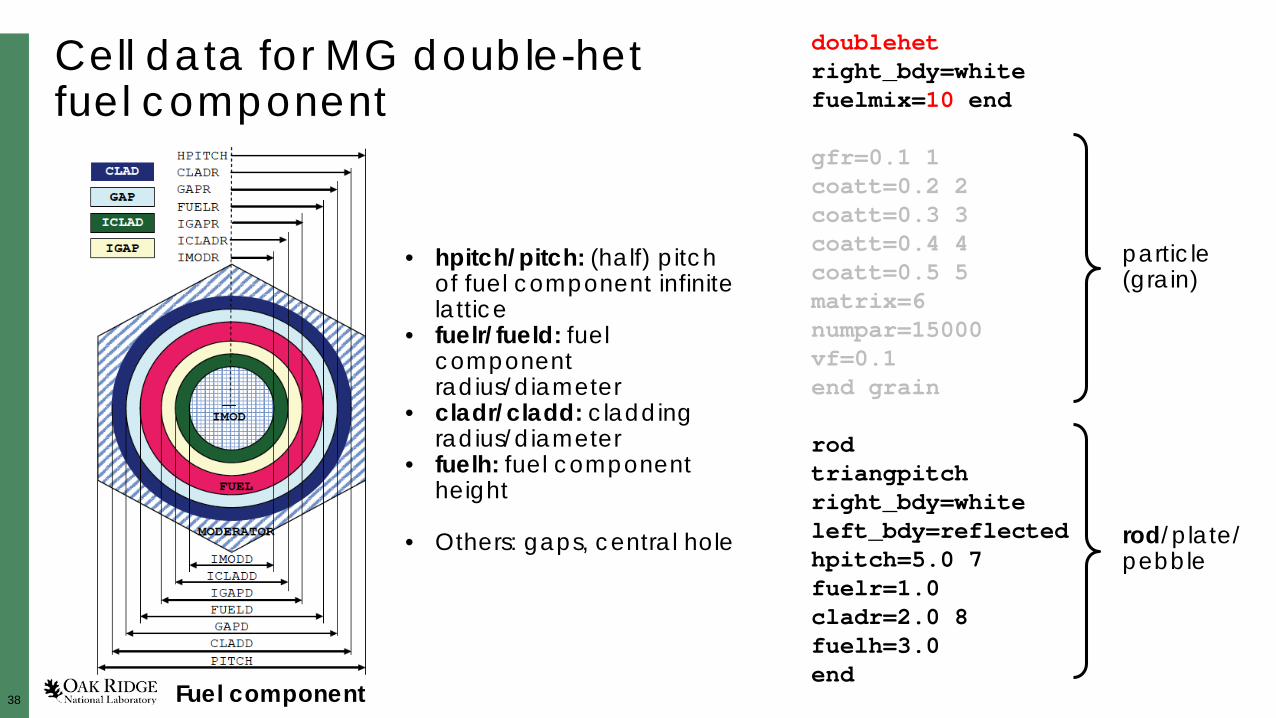
Cell data for MG double-het fuel component
doublehetright_bdy=white fuelmix=10 end
gfr=0.1 1coatt=0.2 2coatt=0.3 3coatt=0.4 4coatt=0.5 5matrix=6 numpar=15000 vf=0.1 end grain
rod triangpitchright_bdy=white left_bdy=reflectedhpitch=5.0 7 fuelr=1.0 cladr=2.0 8 fuelh=3.0 end
particle (grain)
rod/plate/1pebble
• gfr/gfd: fuel grain radius/diameter
• coatt/coatr/coatd: coating thickness, radius, diameter
• numpar: number of particles
• vf: packing fraction
Don’t fall into the d/r/t-trap:
d: diameterr: radiust: thickness
Often both d and r are possible, and for coating, additionally tParticle
38
Cell data for MG double-het fuel component
doublehetright_bdy=white fuelmix=10 end
gfr=0.1 1coatt=0.2 2coatt=0.3 3coatt=0.4 4coatt=0.5 5matrix=6 numpar=15000 vf=0.1 end grain
rod triangpitchright_bdy=white left_bdy=reflectedhpitch=5.0 7 fuelr=1.0 cladr=2.0 8 fuelh=3.0 end
particle (grain)
rod/plate/pebble
• hpitch/pitch: (half) pitch of fuel component infinite lattice
• fuelr/fueld: fuel component radius/diameter
• cladr/cladd: cladding radius/diameter
• fuelh: fuel component height
• Others: gaps, central hole
Fuel component

39
SCALE/KENO-VI double-het multigroup model
• Steps1. Create double-het cell block2. Place fuel mix into volume that includes
the particles
• Fuel pebbleglobal unit 1sphere 1 2.5sphere 2 3.0cuboid 3 6p3.0media 10 1 1media 106 1 2 -1media 300 1 3 -2boundary 3

40
Outline
• Introduction– What are double heterogeneous systems?– What are the challenges for modeling these systems?
• Modeling double-het systems with SCALE/KENO-VI
• SCALE hands-on: Part 1 (together)• SCALE hands-on: Part 2 (alone)
• Other SCALE capabilities for double-het systems
• Outlook to SCALE 6.3

41
High-temperature gas-cooled reactor (HTGR) prismatic pin cell in infinite lattice
Use provided SCALE composition block htgr-prismatic-pin-cell-composition.txt
Use Fulcrum’s auto-completion!
Ref.: G. Strydom, F. Bostelmann, INL/EXT-15-34868, Rev. 1.
1. Multigroup model using the double-het cell
2. Continuous-energy model using an infinite array of particles
MHTGR pin cell

42
HTGR prismatic pin cell in infinite lattice
Parameter Dimension (cm)
TRISO fuel particle
UC0.5O1.5 kernel radius 2.125E-02Porous carbon buffer layer outer radius 3.125E-02Inner PyC outer radius 3.525E-02SiC outer radius 3.875E-02Outer PyC outer radius 4.275E-02
Average TRISO packing fraction 0.35Fuel compact outer radius 0.6225Fuel/helium gap outer radius 0.6350Large helium coolant channel radius 0.7940Unit cell pitch 1.8796Fuel compact height 4.9280
Dimensions for MHTGR pin cell
MHTGR pin cell

43
Outline
• Introduction– What are double heterogeneous systems?– What are the challenges for modeling these systems?
• Modeling double-het systems with SCALE/KENO-VI
• SCALE hands-on: Part 1 (together)
• SCALE hands-on: Part 2 (alone)• Other SCALE capabilities for double-het systems
• Outlook to SCALE 6.3

44
HTGR fuel pebble in infinite cubic lattice
UO2 fuel density (g/cm3) 10.4
Uranium enrichment 17 wt.%
Fuel kernel radius (cm) 0.025
Fuel particle coating layer materials (starting from kernel) Buffer/PyC/SiC/PyC
Fuel particle coating layer thicknesses (cm) 0.009/0.004/0.0035/0.004
Fuel particle coating layer densities (g/cm3) 1.1/1.9/3.18/1.9
Number of particles in pebble 8,385
Diameter of fuel pebble (cm) 3.0
Diameter of fuel zone in pebble (cm) 2.5
Graphite matrix and fuel pebble outer shell density (g/cm3) 1.73
Use provided SCALE composition block htgr-fuel-pebble-composition.txt
1. MG model using the double-het cell
2. CE model using an infinite array of particles
HTR fuel pebble
45
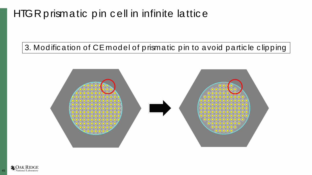
HTGR prismatic pin cell in infinite lattice
3. Modification of CE model of prismatic pin to avoid particle clipping

46
Outline
• Introduction– What are double heterogeneous systems?– What are the challenges for modeling these systems?
• Modeling double-het systems with SCALE/KENO-VI
• SCALE hands-on: Part 1 (together)
• SCALE hands-on: Part 2 (alone)
• Other SCALE capabilities for double-het systems• Outlook to SCALE 6.3

47
What else can we do with double-het systems in SCALE?
• 2D deterministic code calculations using NEWT
• Depletion calculations using Triton in combination with NEWT and KENO-VI (both MG and CE)
• Uncertainty and sensitivity analysis: – Perturbation theory: CE TSUNAMI (using KENO-VI CE as transport code)– Random sampling: Sampler (using either NEWT or KENO-VI MG)

48
Outline
• Introduction– What are double heterogeneous systems?– What are the challenges for modeling these systems?
• Modeling double-het systems with SCALE/KENO-VI
• SCALE hands-on: Part 1 (together)
• SCALE hands-on: Part 2 (alone)
• Other SCALE capabilities for double-het systems
• Outlook to SCALE 6.3

49
Outlook to SCALE 6.3
• New data libraries:– 1597-group cross
section library– ENDF/B-VIII.0 data,
offering graphite as perfect crystal, with 10% and 30% porosity ( cf. presentation about SCALE double-het capabilities)
238U capture cross section; HTR neutron flux

50
Outlook to SCALE 6.3• New Monte Carlo code Shift
– MG and CE calculations– Use of KENO-VI input via CsasShift sequence (csas6-shift)– Other supported input formats: own format and MCNP input– New block to simplify random placement of particles in CE mode:unit 1com=‘TRISO particle'sphere 1 2.50e-02sphere 2 3.40e-02sphere 3 3.80e-02sphere 4 4.15e-02sphere 5 4.55e-02media 100 1 1media 101 1 2 -1media 102 1 3 -2media 103 1 4 -3media 104 1 5 -4boundary 5
global unit 10com=‘fuel pebble'sphere 1 2.5sphere 2 3.0cuboid 3 6p5.0media 105 1 1 randommix='trisos'media 106 1 2 -1media 300 1 3 -2boundary 3
read randomgeomrandommix = 'trisos'type=randomunits=1 endpfs=0.05054954 endclip=noseed=1111end randommixend randomgeom