kenwood vr707 manual
TRANSCRIPT
AUDIO VIDEO SURROUND RECEIVER
VR-707KRF-V6070DINSTRUCTION MANUALKENWOOD CORPORATION
B60-5330-00 00 ID (K, P, M, X) 0211
This instruction manual is for some models. Model availability and features
(functions) may differ depending on the country and sales area.
About the supplied remote controlCompared to standard remote controls, the remote control supplied with this receiver has severaloperation modes. These modes enable the remote control to control other audio/video components. Inorder to effectively use the remote control it is important to read the operating instructions and obtain aproper understanding of the remote control and how to switch its operation modes (etc.).Using the remote control without completely understanding its design and how to switch the operationmodes may result in incorrect operations.
*5330/01-07/EN 1/21/03, 9:54 PM1
2 EN
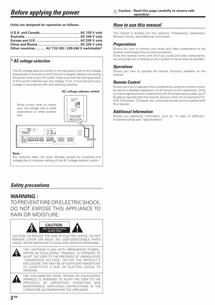
Before applying the power Caution : Read this page carefully to ensure safeoperation.
* AC voltage selection
The AC voltage selector switch on the rear panel is set to the voltagethat prevails in the area to which the unit is shipped. Before connectingthe power cord to your AC outlet, make sure that the setting positionof this switch matches your line voltage. If not, it must be set to yourvoltage in accordance with the following direction.
AC voltage selector switch
Note :
Our warranty does not cover damage caused by excessive linevoltage due to improper setting of the AC voltage selector switch.
Move switch lever to matchyour line voltage with a smallscrewdriver or other pointedtool.
How to use this manualThis manual is divided into four sections, Preparations, Operations,Remote Control, and Additional Information.
PreparationsShows you how to connect your audio and video components to thereceiver and prepare the surround processor.Since this receiver works with all of your audio and video components,we will guide you in setting up your system to be as easy as possible.
OperationsShows you how to operate the various functions available on thereceiver.
Remote ControlShows you how to operate other components using the remote control,as well as a detailed explanation of all remote control operations. Onceyou have registered your components with the proper setup codes, you’llbe able to operate both this receiver and your other AV components (TV,VCR, DVD player, CD player, etc.) using the remote control supplied withthis receiver.
Additional InformationShows you additional information such as “In case of difficulty”(troubleshooting) and “Specifications”.
Safety precautions
WARNING :
TO PREVENT FIRE OR ELECTRIC SHOCK,DO NOT EXPOSE THIS APPLIANCE TORAIN OR MOISTURE.
CAUTIONRISK OF ELECTRIC SHOCK
DO NOT OPEN
CAUTION: TO REDUCE THE RISK OF ELECTRIC SHOCK, DO NOTREMOVE COVER (OR BACK). NO USER-SERVICEABLE PARTSINSIDE. REFER SERVICING TO QUALIFIED SERVICE PERSONNEL.
THE LIGHTNING FLASH WITH ARROWHEAD SYMBOL,WITHIN AN EQUILATERAL TRIANGLE, IS INTENDED TOALERT THE USER TO THE PRESENCE OF UNINSULATED“DANGEROUS VOLTAGE” WITHIN THE PRODUCT’SENCLOSURE THAT MAY BE OF SUFFICIENT MAGNITUDETO CONSTITUTE A RISK OF ELECTRIC SHOCK TOPERSONS.
THE EXCLAMATION POINT WITHIN AN EQUILATERALTRIANGLE IS INTENDED TO ALERT THE USER TO THEPRESENCE OF IMPORTANT OPERATING ANDMAINTENANCE (SERVICING) INSTRUCTIONS IN THELITERATURE ACCOMPANYING THE APPLIANCE.
Units are designed for operation as follows.
U.S.A. and Canada ........................................... AC 120 V only
Australia ........................................................... AC 240 V only
Europe and U.K. ............................................... AC 230 V only
China and Russia ............................................. AC 220 V only
Other countries .......... AC 110-120 / 220-240 V switchable*
+
-
VOLTAGESELECTOR
AC 110-120V~
AC 220-240V~
*5330/01-07/EN 1/21/03, 9:54 PM2
3 EN
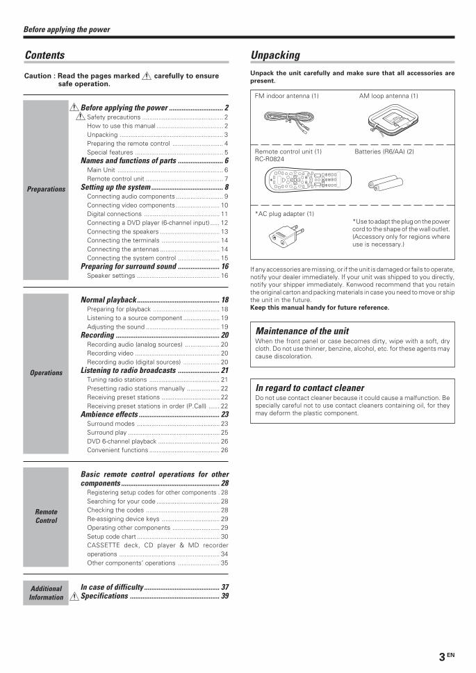
UnpackingUnpack the unit carefully and make sure that all accessories are
present.
FM indoor antenna (1) AM loop antenna (1)
Remote control unit (1) Batteries (R6/AA) (2)RC-R0824
4¢
+
*AC plug adapter (1)*Use to adapt the plug on the powercord to the shape of the wall outlet.(Accessory only for regions whereuse is necessary.)
If any accessories are missing, or if the unit is damaged or fails to operate,notify your dealer immediately. If your unit was shipped to you directly,notify your shipper immediately. Kenwood recommend that you retainthe original carton and packing materials in case you need to move or shipthe unit in the future.Keep this manual handy for future reference.
Before applying the power .............................. 2Safety precautions ............................................. 2How to use this manual ..................................... 2Unpacking .......................................................... 3Preparing the remote control ............................ 4Special features ................................................. 5
Names and functions of parts ......................... 6Main Unit ........................................................... 6Remote control unit ........................................... 7
Setting up the system ........................................ 8Connecting audio components .......................... 9Connecting video components ........................ 10Digital connections .......................................... 11Connecting a DVD player (6-channel input) ..... 12Connecting the speakers ................................. 13Connecting the terminals ................................ 14Connecting the antennas ................................. 14Connecting the system control ....................... 15
Preparing for surround sound ....................... 16Speaker settings .............................................. 16
Normal playback.............................................. 18Preparing for playback ..................................... 18Listening to a source component .................... 19Adjusting the sound ......................................... 19
Recording .......................................................... 20Recording audio (analog sources) ................... 20Recording video ............................................... 20Recording audio (digital sources) .................... 20
Listening to radio broadcasts ....................... 21Tuning radio stations ....................................... 21Presetting radio stations manually .................. 22Receiving preset stations ................................ 22Receiving preset stations in order (P.Call) ...... 22
Ambience effects ............................................. 23Surround modes .............................................. 23Surround play ................................................... 25DVD 6-channel playback .................................. 26Convenient functions ....................................... 26
Basic remote control operations for othercomponents ....................................................... 28
Registering setup codes for other components . 28Searching for your code ................................... 28Checking the codes ......................................... 28Re-assigning device keys ................................ 29Operating other components .......................... 29Setup code chart .............................................. 30CASSETTE deck, CD player & MD recorderoperations ........................................................ 34Other components’ operations ....................... 35
In case of difficulty .......................................... 37Specifications .................................................. 39
Contents
Caution : Read the pages marked carefully to ensuresafe operation.
Before applying the power
Preparations
Operations
AdditionalInformation
Maintenance of the unitWhen the front panel or case becomes dirty, wipe with a soft, drycloth. Do not use thinner, benzine, alcohol, etc. for these agents maycause discoloration.
In regard to contact cleanerDo not use contact cleaner because it could cause a malfunction. Bespecially careful not to use contact cleaners containing oil, for theymay deform the plastic component.
RemoteControl
*5330/01-07/EN 1/21/03, 9:54 PM3
4 EN
Before applying the power
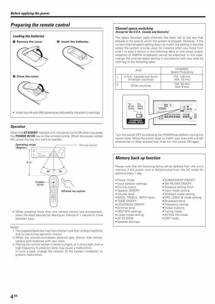
4
¢ + +
+
6 m
POWER RCVR
Operation
When the STANDBY indicator is lit, the power turns ON when you pressthe POWER RCVR key on the remote control. When the power comesON, press the key you want to operate.
• When pressing more than one remote control key successively,press the keys securely by leaving an interval of 1 second or morebetween keys.
Notes1. The supplied batteries may have shorter lives than ordinary batteries
due to use during operation checks.2. When the remote-controllable distance gets shorter than before,
replace both batteries with new ones.3. Placing the remote sensor in direct sunlight, or in direct light from a
high frequency fluorescent lamp may cause a malfunction.In such a case, change the location of the system installation toprevent malfunction.
Preparing the remote control
Loading the batteries1 Remove the cover. 2 Insert the batteries.
3 Close the cover.
• Insert two AA-size (R6) batteries as indicated by the polarity markings.
Operating range
(Approx.)Remote sensor
Infrared ray system
Channel space switching(Except for the U.S.A., Canada and Australia)
The space between radio channels has been set to the one thatprevails in the area to which the system is shipped. However, if thecurrent channel space setting does not match the setting in the areawhere the system is to be used, for instance when you move fromarea 1 or area 2 shown in the following table or vice versa, properreception of AM/FM broadcasts cannot be expected. In this case,change the channel space setting in accordance with your area byreferring to the following table.
Turn the power OFF by pressing the POWER key before moving theswitch level. Move the switch lever to match your area with a smallscrewdriver or other pointed tool, then turn the power ON again.
1.
2.
CHANNELSpace Frequency
Area
U.S.A., Canada and SouthAmerican countries
Other countries
FM: 100 kHzAM: 10 kHz
FM: 50 kHzAM: 9 kHz
DEEMCHSP
50µAM 9kHFM 50kH
DE-EMPHASISCHANNEL SPACE
50us AM 9kHz FM50kHz
75us AM 10kHz FM100kHz
50us AM 9kHz FM50kHz
75us AM 10kHz FM100kHz
DE-EMPHASISCHANNEL SPACE
Memory back up function
Please note that the following items will be deleted from the unit'smemory if the power cord is disconnected from the AC outlet forapproximately 1 day.
• Power mode. • SUBWOOFER ON/OFF.• Input selector settings. • SW RE-MIX ON/OFF.• Picture output. • Distance setting timer.• Speaker ON/OFF. • Input mode setting.• Volume level. • Midnight mode setting.• BASS, TREBLE, INPUT level. • PRO LOGIC II mode setting.• TONE ON/OFF. • Broadcast band.• LOUDNESS ON/OFF. • Frequency setting.• Dimmer level. • Preset stations.• MD/TAPE settings. • Tuning mode.• Listen mode setting. • ACTIVE EQ mode.• SP SYSTEM. • DSP mode.• Speaker settings.
*5330/01-07/EN 1/21/03, 9:54 PM4
5 EN
Before applying the power
For the U.S.A.
Note to CATV system installerThis reminder is provided to call the CATV system installer's attentionto Article 820-40 of the NEC that provides guidelines for propergrounding and, in particular, specifies that the cable ground shall beconnected to the grounding system of the building, as close to thepoint of cable entry as practical.
FCC WARNINGThis equipment may generate or use radio frequency energy. Changesor modifications to this equipment may cause harmful interferenceunless the modifications are expressly approved in the instructionmanual. The user could lose the authority to operate this equipmentif an unauthorized change or modification is made.
NOTE:This equipment has been tested and found to comply with the limitsfor a Class B digital device, pursuant to Part 15 of the FCC Rules.These limits are designed to provide reasonable protection againstharmful interference in a residential installation. This equipment maycause harmful interference to radio communications, if it is notinstalled and used in accordance with the instructions. However,there is no guarantee that interference will not occur in a particularinstallation. If this equipment does cause harmful interference toradio or television reception, which can be determined by turning theequipment off and on, the user is encouraged to try to correct theinterference by one or more of the following measures:– – Reorient or relocate the receiving antenna.– – Increase the separation between the equipment and receiver.– – Connect the equipment into an outlet on a circuit different from
that to which the receiver is connected.– – Consult the dealer or an experienced radio / TV technician for
help.
For the U.S.A. Special features
True home theater soundThis receiver incorporates a wide variety of surround modes to bring youmaximum enjoyment from your video software. Select a surround modeaccording to your equipment or the software you are going to play andenjoy! £
Dolby Digital and Dolby Digital EXThe DOLBY DIGITAL mode lets you enjoy full digital surround fromsoftware processed in the Dolby Digital format. Dolby Digital provides upto 5.1 channels of independent digital audio for better sound quality andmore powerful presence than conventional Dolby Surround. As for DolbyDigital EX, it creates six full-bandwidth output channels from the 5.1channel sources. This is done using a matrix decoder that derives threesurround channels from the two in the original recording. For best result,Dolby Digital EX should be used with movie soundtracks recorded withDolby Digital Surround EX.
Dolby PRO LOGIC IIDOLBY PRO LOGIC II, whilst totally compatible with its predecessorPRO LOGIC, provides greater advantages in surround sound. It allowsuser to enjoy the conventional stereo or Dolby Surround with a convincing“5.1 like” presentation. PRO LOGIC II offers special features for controllingthe overall spatial, dimensionality and frontal sound field imaging. PROLOGIC II produces an impressive surround sound from video softwaremarked and three-dimensional space from music CD.When listening to music, you will be able to enjoy the experience of sheerSTEREO surround sound.
DTSDTS (Digital Theater System) is a 5.1 channel digital audio format thatprovides five full-spectrum channels and one low-frequency (subwoofer)channel for unprecedented clarity, optimum channel separation and a(wide) dynamic range.In the DTS mode, the 5.1 channel digital input from a DTS CD, LD or DVDdisc (carrying the “DTS” marking) can be played in Digital Surround.Important:When a DTS disc is played on a CD, LD or DVD player, noise may beoutput from the analog output. It is recommended that you connect thedigital output of the player to the digital input of this unit.
DSP surround modesThe DSP (Digital Signal Processor) used for this receiver incorporates avariety of high quality adjustable sound fields, like “ARENA”, “JAZZCLUB”, THEATER”, STADIUM” and “DISCO”. It is compatible withalmost any kind of program source.
DVD 6-channel inputIf you own a DVD player equipped with 6-channel output, this receiverallows you to obtain the full surround sound impact of DVD sourcematerial featuring multi-channel encoding. Since the source signals aredigital and each channel is input independently, the resulting ambienceis far superior to what can be achieved with conventional surround soundsystems.
ACTIVE EQACTIVE EQ mode will produce a more dynamic sound quality in anycondition. You can enjoy a more impressive sound effect when ACTIVEEQ is turned on during Dolby Digital and DTS playback.
Universal IR (InfraRed) remote controlIn addition to the basic receiver, the remote control supplied with thisreceiver can also operate almost all of your remote controllable audio andvideo components. Just follow the simple setup procedure to registerthe components you have connected.
As an ENERGY STAR® Partner, Kenwood
Corporation has determined that this
product meets the ENERGY STAR®
guidelines for energy efficiency.This
product can save energy. Saving energy
reduces air pollution and lowers utility bills.
*5330/01-07/EN 1/21/03, 9:54 PM5
6 EN
POWERSTANDBY
ON ⁄ STANDBY
A B
POWER
STANDBY
DIMMER
SPEAKERS ON ⁄ OFF
PHONES ACTIVE EQ
LISTEN MODE
INPUT MODE BAND AUTO MEMORY
ACTIVE EQ DTS
SOUND
MULTI CONTROL INPUT SELECTORDOWN
MUTE
UP
VOLUME CONTROL
ON OFF
ON ⁄ STANDBY
DOLBY DIGITAL EX
SETUP
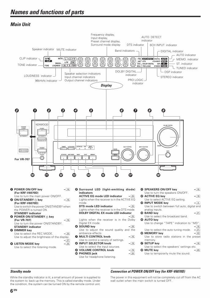
Names and functions of parts
1 POWER ON/OFF key ^(For KRF-V6070D)
Use to turn the main power ON/OFF.2 ON/STANDBY key ^
(For KRF-V6070D)
Use to switch the power ON/STANDBY whenthe POWER is turned ON.STANDBY indicator
2 POWER ON/STANDBY key
(For VR-707) ^Use to turn the power ON/STANDBY.STANDBY indicator
3 DIMMER key
Use to select the REC MODE. )Use to adjust the brightness of the display.
¶4 LISTEN MODE key ∞
Use to select the listening mode.
5 Surround LED (light-emitting diode)
indicators
ACTIVE EQ mode LED indicator )Lights when the receiver is in the ACTIVE EQmode.DTS mode LED indicator ∞Lights when the receiver is in the DTS mode.DOLBY DIGITAL EX mode LED indicator
∞Lights when the receiver is in the DolbyDigital EX mode.
6 SOUND key §Use to adjust the sound quality and theambience effects.
7 MULTI CONTROL knob ^Use to control a variety of settings.
8 INPUT SELECTOR knob (Use to select the input sources.
9 VOLUME CONTROL knob (0 PHONES jack )
Use for headphone listening.
! SPEAKERS ON/OFF key *Use to turn the speakers ON/OFF.
@ ACTIVE EQ key (Use to select ACTIVE EQ setting.
# INPUT MODE key 8Use to switch between full auto, digital andanalog inputs.
$ BAND key ¡Use to select the broadcast band.
% AUTO key
Use to change “TAPE” indication to “MD”.*
Use to select the auto tuning mode. ¡^ MEMORY key ™
Use to store radio stations in the presetmemory.
& SETUP key ^Use to select the speakers' settings etc.
* MUTE key )Use to temporarily mute the sound.
Main Unit
For VR-707
Standby mode
While the standby indicator is lit, a small amount of power is supplied tothe system to back-up the memory. This is called standby mode. Underthe condition, the system can be turned ON by the remote control unit.
Display
Speaker selection indicatorsInput channel indicatorsOutput channel indicators
Band indicators
STEREO indicator
Frequency display,Input display,Preset channel display,Surround mode display
Speaker indicator
PRO LOGICindicator
AUTO DETECTindicator
DOLBY DIGITALindicator
DTS indicator
CLIP indicatorAUTO indicator
MEMO. indicator
ST. indicator
TUNED indicator
MUTE indicator
TONE indicator
LOUDNESS indicator
96kHzfs indicator
DSP indicator
DIGITAL indicator
6CH INPUT indicator
Connection at POWER ON/OFF key (for KRF-V6070D)
The power in this equipment will not be completely cut off from the ACwall outlet when the main switch is turned OFF.
*5330/01-07/EN 1/21/03, 9:54 PM6
7 EN
Names and functions of parts
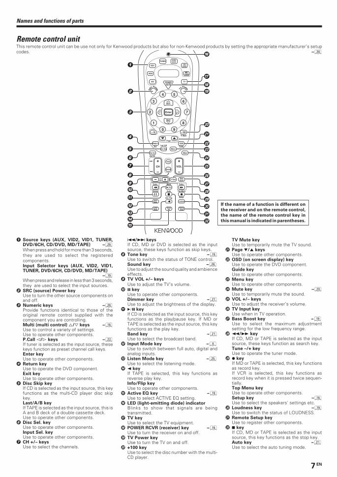
Remote control unitThis remote control unit can be use not only for Kenwood products but also for non-Kenwood products by setting the appropriate manufacturer’s setupcodes. º
If the name of a function is different on
the receiver and on the remote control,
the name of the remote control key in
this manual is indicated in parentheses.
SR
C Power TVPower
5
6
8
9
4
3
2
1
0
7
Dimmer
Tune – Tune +Band
Setup
Top MenuAuto
Info / Flip
Loudness
ListenMode
InputMode
Sound
Tone
TVVOL
Mute
4
¢
VOL
+
–CH
+
–
Menu
Disc Sel.
Input Sel.
OSD
Guide
Return
Exit
Page
TV Mute
Disc Skip
Last / A/B
+ 10 + 100
Multi
Multi
P. C
all P
. Call
Enter
TVAUX POWERRCVR
VID2
VID1
DVD6CH
CDDVD
MDTAPE
TUNER
– + TV Input BassBoost
RemoteSetup
ActiveEQ
1
2
3
6
$%
7
)
™
•
ª
º
⁄
¤
^
(
!
4
5
8
9
@
&
*
¡
¶
£
¢
∞
§
#
0
1 Source keys (AUX, VID2, VID1, TUNER,DVD/6CH, CD/DVD, MD/TAPE) •When press and hold for more than 3 seconds,they are used to select the registeredcomponents.Input Selector keys (AUX, VID2, VID1,TUNER, DVD/6CH, CD/DVD, MD/TAPE)
(When press and release in less than 3 seconds,they are used to select the input sources.
2 SRC (source) Power keyUse to turn the other source components onand off.
3 Numeric keys •Provide functions identical to those of theoriginal remote control supplied with thecomponent you are controlling.Multi (multi control) %/fi keys ^Use to control a variety of settings.Use to operate other components.P.Call @/# keys ™If tuner is selected as the input source, thesekeys function as preset channel call keys.Enter keyUse to operate other components.
4 Return keyUse to operate the DVD component.Exit keyUse to operate other components.
5 Disc Skip keyIf CD is selected as the input source, this keyfunctions as the multi-CD player disc skipkey.Last/A/B keyIf TAPE is selected as the input source, this isA and B deck of a double cassette deck.Use to operate other components.
6 Disc Sel. keyUse to operate other components.Input Sel. keyUse to operate other components.
7 CH +/– keysUse to select the channels.
4/¢ keysIf CD, MD or DVD is selected as the inputsource, these keys function as skip keys.
8 Tone key (Use to switch the status of TONE control.Sound key §Use to adjust the sound quality and ambienceeffects.
9 TV VOL +/– keys
Use to adjust the TV’s volume.0 8 key
Use to operate other components.Dimmer key ¶Use to adjust the brightness of the display.
! 6 keyIf CD is selected as the input source, this keyfunctions as the play/pause key. If MD orTAPE is selected as the input source, this keyfunctions as the play key.Band key ¡Use to select the broadcast band.
@ Input Mode key 8Use to switch between full auto, digital andanalog inputs.
# Listen Mode key ∞Use to select the listening mode.
$ 2 keyIf TAPE is selected, this key functions asreverse play key.Info/Flip keyUse to operate other components.
% Active EQ key (Use to select ACTIVE EQ setting.
^ LED (light-emitting diode) indicatorBlinks to show that signals are beingtransmitted.
& TV keyUse to select the TV equipment.
* POWER RCVR (receiver) key ^Use to turn the receiver on and off.
( TV Power keyUse to turn the TV on and off.
) +100 keyUse to select the disc number with the multi-CD player.
TV Mute keyUse to temporarily mute the TV sound.
¡ Page ∞/5 keysUse to operate other components.
™ OSD (on screen display) keyUse to operate the DVD component.Guide keyUse to operate other components.
£ Menu keyUse to operate other components.
¢ Mute key )Use to temporarily mute the sound.
∞ VOL +/– keysUse to adjust the receiver’s volume.
§ TV Input keyUse when in TV operation.
¶ Bass Boost key (Use to select the maximum adjustmentsetting for the low frequency range.
• 1/¡ keyIf CD, MD or TAPE is selected as the inputsource, these keys function as search key.Tune –/+ keyUse to operate the tuner mode.
ª ¶ keyIf MD or TAPE is selected, this key functionsas record key.If VCR is selected, this key functions asrecord key when it is pressed twice sequen-tially.Top Menu keyUse to operate other components.Setup key ^Use to select the speakers' settings etc.
º Loudness key (Use to switch the status of LOUDNESS.
⁄ Remote Setup keyUse to register other components.
¤ 7 keyIf CD, MD or TAPE is selected as the inputsource, this key functions as the stop key.Auto key ¡Use to select the auto tuning mode.
*5330/01-07/EN 1/21/03, 9:54 PM7
8 EN
Setting up the system
Make connections as shown in the following pages.
When connecting the related system components, be
sure to refer to the instruction manuals supplied with
the components you are connecting.
Do not connect the power cord to a wall outlet until all
connections are completed.
Notes1. Be sure to insert all connection cords securely. If their connections are
imperfect, the sound may not be produced or there will be noiseinterference.
2. Be sure to remove the power cord from the AC outlet before pluggingor unplugging any connection cords. Plugging/unplugging connectioncords without disconnecting the power cord can cause malfunctionsand may damage the unit.
3. Do not connect power cords from components whose powerconsumption is larger than what is indicated on the AC outlet at therear of this unit.
Analog connectionsAudio connections are made using RCA pin cords. These cables transferstereo audio signal in an “analog” form. This means the audio signalcorresponds to the actual audio of two channels. These cables usuallyhave 2 plugs at each end, red for the right channel and white for the leftchannel. These cables are usually packed together with the source unit,or are available at your local electronics retailer.
Microcomputer malfunctionIf operation is not possible or an erroneous display appears, eventhough all connections have been made properly, reset themicrocomputer by referring to “In case of difficulty”. ‡
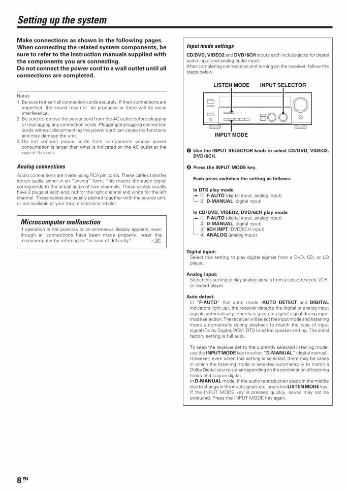
Input mode settingsCD/DVD, VIDEO2 and DVD/6CH inputs each include jacks for digitalaudio input and analog audio input.After completing connections and turning on the receiver, follow thesteps below.
1 Use the INPUT SELECTOR knob to select CD/DVD, VIDEO2,
DVD/6CH.
2 Press the INPUT MODE key.
Each press switches the setting as follows:
In DTS play mode
1 F-AUTO (digital input, analog input)2 D-MANUAL (digital input)
In CD/DVD, VIDEO2, DVD/6CH play mode
1 F-AUTO (digital input, analog input)2 D-MANUAL (digital input)3 6CH INPT (DVD/6CH input)4 ANALOG (analog input)
Digital input:
Select this setting to play digital signals from a DVD, CD, or LDplayer.
Analog input:
Select this setting to play analog signals from a cassette deck, VCR,or record player.
Auto detect:
In “F-AUTO” (full auto) mode (AUTO DETECT and DIGITAL
indicators light up), the receiver detects the digital or analog inputsignals automatically. Priority is given to digital signal during inputmode selection. The receiver will select the input mode and listeningmode automatically during playback to match the type of inputsignal (Dolby Digital, PCM, DTS ) and the speaker setting. The initialfactory setting is full auto.
To keep the receiver set to the currently selected listening mode,use the INPUT MODE key to select “D-MANUAL” (digital manual).However, even when this setting is selected, there may be casesin which the listening mode is selected automatically to match aDolby Digital source signal depending on the combination of listeningmode and source digital.In D-MANUAL mode, if the audio reproduction stops in the middledue to change in the input signals etc, press the LISTEN MODE key.If the INPUT MODE key is pressed quickly, sound may not beproduced. Press the INPUT MODE key again.
INPUT MODE
INPUT SELECTORLISTEN MODE
*5330/08-15/EN 1/21/03, 9:53 PM8
9 EN
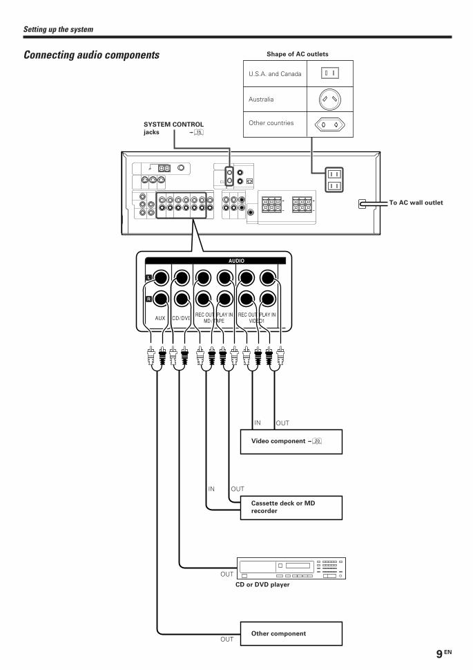
+
-
+
-
AUX CD/DVDREC OUT PLAY IN
VIDEO1REC OUT PLAY IN
MD / TAPE
L
R
AUDIO
Setting up the system
Connecting audio components
IN
OUTIN
OUT
OUT
OUT
To AC wall outlet
SYSTEM CONTROL
jacks %
Shape of AC outlets
Australia
Other countries
U.S.A. and Canada
Cassette deck or MD
recorder
CD or DVD player
Video component )
Other component
*5330/08-15/EN 1/21/03, 9:53 PM9
10 EN
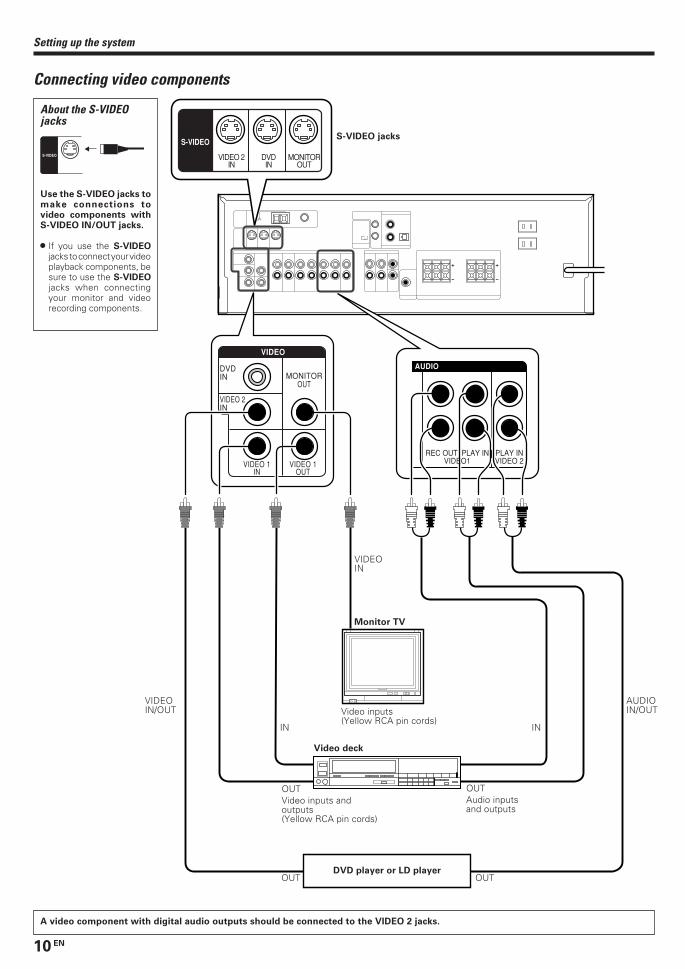
Setting up the system
Connecting video components
A video component with digital audio outputs should be connected to the VIDEO 2 jacks.
+
-
+
-
PLAY INVIDEO 2
REC OUT PLAY INVIDEO1VIDEO 1
OUTVIDEO 1
IN
VIDEO 2IN
DVDIN MONITOR
OUT
VIDEO
AUDIO
VIDEO 2IN
DVDIN
MONITOROUT
S-VIDEO
Video inputs andoutputs(Yellow RCA pin cords)
Audio inputsand outputs
OUT OUT
Monitor TV
Video inputs(Yellow RCA pin cords)
VIDEOIN
Video deck
IN
OUTDVD player or LD player
About the S-VIDEOjacks
S-VIDEO
Use the S-VIDEO jacks tomake connections tovideo components withS-VIDEO IN/OUT jacks.
• If you use the S-VIDEOjacks to connect your videoplayback components, besure to use the S-VIDEOjacks when connectingyour monitor and videorecording components.
OUT
IN
VIDEOIN/OUT
AUDIOIN/OUT
S-VIDEO jacks
*5330/08-15/EN 1/21/03, 9:53 PM10
11 EN
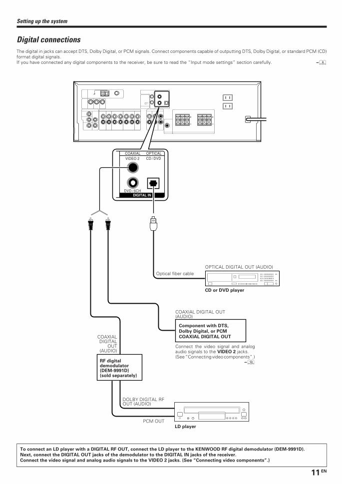
+
-
+
-
VIDEO 2
DVD / 6CH
CD / DVDCOAXIAL OPTICAL
DIGITAL IN
Setting up the system
Digital connectionsThe digital in jacks can accept DTS, Dolby Digital, or PCM signals. Connect components capable of outputting DTS, Dolby Digital, or standard PCM (CD)format digital signals.If you have connected any digital components to the receiver, be sure to read the “Input mode settings” section carefully. 8
Component with DTS,
Dolby Digital, or PCM
COAXIAL DIGITAL OUTCOAXIALDIGITAL
OUT(AUDIO)
DOLBY DIGITAL RFOUT (AUDIO)
LD player
PCM OUT
RF digitaldemodulator(DEM-9991D)(sold separately)
CD or DVD player
OPTICAL DIGITAL OUT (AUDIO)Optical fiber cable
COAXIAL DIGITAL OUT(AUDIO)
Connect the video signal and analogaudio signals to the VIDEO 2 jacks.(See “Connecting video components”.)
0
To connect an LD player with a DIGITAL RF OUT, connect the LD player to the KENWOOD RF digital demodulator (DEM-9991D).
Next, connect the DIGITAL OUT jacks of the demodulator to the DIGITAL IN jacks of the receiver.
Connect the video signal and analog audio signals to the VIDEO 2 jacks. (See “Connecting video components”.)
*5330/08-15/EN 1/21/03, 9:53 PM11
12 EN
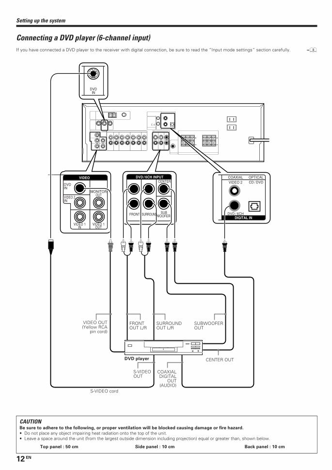
+
-
+
-
CENTER
SUBWOOFER SURROUNDFRONT
VIDEO 1OUT
VIDEO 1IN
VIDEO 2IN
DVDIN
MONITOROUT
VIDEO 2
DVD / 6CH
CD / DVDCOAXIAL OPTICALDVD / 6CH INPUTVIDEO
DIGITAL IN
DVDIN
Setting up the system
Connecting a DVD player (6-channel input)
CAUTIONBe sure to adhere to the following, or proper ventilation will be blocked causing damage or fire hazard.
• Do not place any object impairing heat radiation onto the top of the unit.• Leave a space around the unit (from the largest outside dimension including projection) equal or greater than, shown below.
Top panel : 50 cm Side panel : 10 cm Back panel : 10 cm
If you have connected a DVD player to the receiver with digital connection, be sure to read the “Input mode settings” section carefully. 8
SURROUNDOUT L/R
VIDEO OUT(Yellow RCA
pin cord)
DVD player
SUBWOOFEROUT
CENTER OUT
FRONTOUT L/R
COAXIALDIGITAL
OUT(AUDIO)
S-VIDEOOUT
S-VIDEO cord
*5330/08-15/EN 1/21/03, 9:53 PM12
13 EN
+
-
+
-
CENTERFRONT
+
-
CR L
RED WHITE GREEN
SURROUNDBACKSURROUND
+
-
R
GRAY
L
BLUE PURPLE
SB
SPEAKERS (8-16Ω)
SPEAKERS (8-16Ω)
SUB WOOFER
PRE OUT
Setting up the system
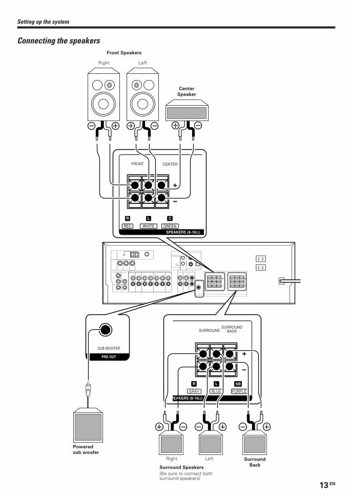
Connecting the speakers
Center
Speaker
Front Speakers
Right Left
Surround
Back
Powered
sub woofer
Right Left
(Be sure to connect bothsurround speakers)
Surround Speakers
*5330/08-15/EN 1/21/03, 9:53 PM13
14 EN
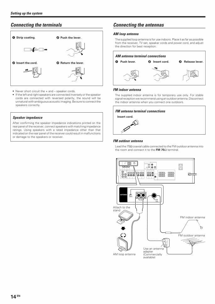
1 Strip coating. 2 Push the lever.
3 Insert the cord. 4 Return the lever.
+
-
+
-
GND
AM
ANTENNA
FM75Ω
Setting up the system
Connecting the terminals
Speaker impedanceAfter confirming the speaker impedance indications printed on therear panel of the receiver, connect speakers with matching impedanceratings. Using speakers with a rated impedance other than thatindicated on the rear panel of the receiver could result in malfunctionsor damage to the speakers or receiver.
• Never short circuit the + and – speaker cords.• If the left and right speakers are connected inversely or the speaker
cords are connected with reversed polarity, the sound will beunnatural with ambiguous acoustic imaging. Be sure to connect thespeakers correctly.
Connecting the antennas
AM loop antennaThe supplied loop antenna is for use indoors. Place it as far as possiblefrom the receiver, TV set, speaker cords and power cord, and adjustthe direction for best reception.
FM indoor antennaThe supplied indoor antenna is for temporary use only. For stablesignal reception we recommend using an outdoor antenna. Disconnectthe indoor antenna when you connect one outdoors.
FM outdoor antennaLead the 75Ω coaxial cable connected to the FM outdoor antenna intothe room and connect it to the FM 75Ω terminal.
AM antenna terminal connections1 Push lever. 2 Insert cord. 3 Release lever.
FM antenna terminal connectionsInsert cord.
Use an antennaadapter(Commerciallyavailable)
Attach to thestand
AM loop antenna
FM indoor antenna
FM outdoor antenna
*5330/08-15/EN 1/21/03, 9:53 PM14
15 EN
Speaker placement
Front speakers : Place to the front left and right of the listeningposition. Front speakers are required for all surround modes.Center speaker : Place front and center. This speaker stabilizes thesound image and helps recreate sound motion. Required for surroundplayback.Surround speakers : Place to the direct left and right, or slightlybehind, the listening position at even heights, approximately 1 meterabove the ears of the listeners. These speakers recreate soundmotion and atmosphere. Required for surround playback.Subwoofer : Reproduces powerful deep bass sounds.Surround back speaker : Place the speaker directly at the rear of thelistening position. The optimum position depends mainly on the roomcondition.
• Although the ideal surround system consists of all the speakerslisted above, if you don't have a center speaker or a subwoofer, youcan divide those signals between the available speakers in thespeaker settings steps to obtain the best possible surroundreproduction from the speakers you have available.
Receiver
Cassette deckor MD recorder
CD player
Record player
Connecting system control cords after connecting a KENWOOD
audio component system lets you take advantage of convenient
system control operations.
This unit is compatible only with the [SL-16] mode. The system
control operation is not available if the unit is connected in the
[XS8], [XS], or [XR] connection mode.
If your component has the mode select switch, set the connected
components to the [SL16] mode.
• You may connect the system control cord to either the up or downjack.
EXAMPLE: [SL16] mode connections
The underlined portion represents the setting of the system controlmode.
• In order to take advantage of the system control operations, thecomponents must be connected to the correct jacks. To use a CDplayer it must be connected to the CD jacks. To use a cassette deck(or MD recorder) it must be connected to the MD/TAPE jacks.When using more than one CD player (etc.) only the one connectedto the specified jacks may be connected for system control.
• Some CD players and cassette decks are not compatible with the[SL16] system control mode. Do not make system connectionswith equipment that is not [SL16] compatible.
• Some MD players are not system control compatible. You cannotmake system control connections to this kind of equipment.
Notes1. [SL16] equipment cannot be combined with [XR], [XS], and [XS8]
equipment for system operations. If your equipment consists ofthis kind of combination, please do not connect any system controlcords. Even without system control cords, normal operations canbe carried out without affecting performance.
2. Do not connect system control cords to any components otherthan those specified by KENWOOD. It may cause a malfunctionand damage your equipment.
3. Be sure the system control plugs are inserted all the way in to thesystem control terminals.
Connecting the system control
Setting up the system
SYSTEM CONTROLcord
SYSTEM CONTROL OPERATIONSRemote Control
Lets you operate this unit with the system remote supplied with thereceiver.
Automatic Operation
When you start playback from a source component, the input selectoron this unit switches to that component automatically.
Synchronized Recording
Lets you synchronize recording with the start of playback whenrecording from CD, MD or analog discs.
SYSTEM CONTROL
SYSTEMCONTROLcord
[SL16]
[SL16] [XS] [XS8] [XR]
[SL16] [XS] [XS8]
[XS]
Frontspeaker
Subwoofer
Center speaker
Listeningposition
Surround backspeaker
Surroundspeaker
*5330/08-15/EN 1/21/03, 9:53 PM15
16 EN
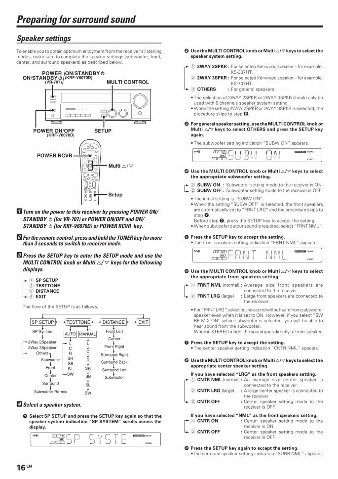
Preparing for surround sound
Speaker settingsTo enable you to obtain optimum enjoyment from the receiver’s listeningmodes, make sure to complete the speaker settings (subwoofer, front,center, and surround speakers) as described below.
1Turn on the power to this receiver by pressing POWER ON/STANDBY (for VR-707) or POWER ON/OFF and ON/STANDBY (for KRF-V6070D) or POWER RCVR key.
2For the remote control, press and hold the TUNER key for morethan 3 seconds to switch to receiver mode.
3Press the SETUP key to enter the SETUP mode and use theMULTI CONTROL knob or Multi %/ fi keys for the followingdisplays.
1 SP SETUP
2 TESTTONE
3 DISTANCE
4 EXIT
The flow of the SETUP is as follows;
SP SETUP TESTTONE DISTANCE EXIT
Front Left
Center
Front Right
Surround Right
Surround Back
Surround Left
Subwoofer
SP System
LCR
SRSBSLSW
L
C
R
SR
SB
SL
SW
MANUALAUTO
2Way 2Speaker2Way 3Speaker
Others
Subwoofer
Front
Center
Surround
Subwoofer Re-mix
4Select a speaker system.
1 Select SP SETUP and press the SETUP key again so that the
speaker system indication “SP SYSTEM” scrolls across the
display.
2 Use the MULTI CONTROL knob or Multi %/fi keys to select the
speaker system setting.
1 2WAY 2SPKR : For selected Kenwood speaker – for example,KS-307HT.
2 2WAY 3SPKR : For selected Kenwood speaker – for example,KS-707HT.
3 OTHERS : For general speakers.
• The selection of 2WAY 2SPKR or 2WAY 3SPKR should only beused with 6 channels speaker system setting.
• When the setting 2WAY 2SPKR or 2WAY 3SPKR is selected, theprocedure skips to step 5.
3 For general speaker setting, use the MULTI CONTROL knob or
Multi %/fi keys to select OTHERS and press the SETUP key
again.
• The subwoofer setting indication “SUBW ON” appears.
4 Use the MULTI CONTROL knob or Multi %/fi keys to select
the appropriate subwoofer setting.
1 SUBW ON : Subwoofer setting mode to the receiver is ON.2 SUBW OFF : Subwoofer setting mode to the receiver is OFF.
• The initial setting is “SUBW ON”.• When the setting “SUBW OFF” is selected, the front speakers
are automatically set to “FRNT LRG” and the procedure skips tostep 7.Before step 7, press the SETUP key to accept the setting.
• When subwoofer output sound is required, select “FRNT NML”.
5 Press the SETUP key to accept the setting.
• The front speakers setting indication “FRNT NML” appears.
6 Use the MULTI CONTROL knob or Multi %/fi keys to select
the appropriate front speakers setting.
1 FRNT NML (normal) : Average size front speakers areconnected to the receiver.
2 FRNT LRG (large) : Large front speakers are connected tothe receiver.
• For “FRNT LRG” selection, no sound will be heard from subwooferspeaker even when it is set to ON. However, if you select “SWRE-MIX ON” when subwoofer is selected, you will be able tohear sound from the subwoofer.When in STEREO mode, the sound goes directly to front speaker.
7 Press the SETUP key to accept the setting.
• The center speaker setting indication “CNTR NML” appears.
8 Use the MULTI CONTROL knob or Multi %/fi keys to select the
appropriate center speaker setting.
If you have selected “LRG” as the front speakers setting,
1 CNTR NML (normal) : An average size center speaker isconnected to the receiver.
2 CNTR LRG (large) : A large center speaker is connected tothe receiver.
3 CNTR OFF : Center speaker setting mode to thereceiver is OFF.
If you have selected “NML” as the front speakers setting,
1 CNTR ON : Center speaker setting mode to thereceiver is ON.
2 CNTR OFF : Center speaker setting mode to thereceiver is OFF.
9 Press the SETUP key again to accept the setting.
•The surround speaker setting indication “SURR NML” appears.
4
¢ + +
+
MULTI CONTROL
SETUP
Setup
POWER RCVR
Multi % / fi
(KRF-V6070D)POWER ON/OFF
ON/STANDBY(KRF-V6070D)
(VR-707)
POWERON/STANDBY
*5330/16-22/EN 1/21/03, 9:55 PM16
17 EN
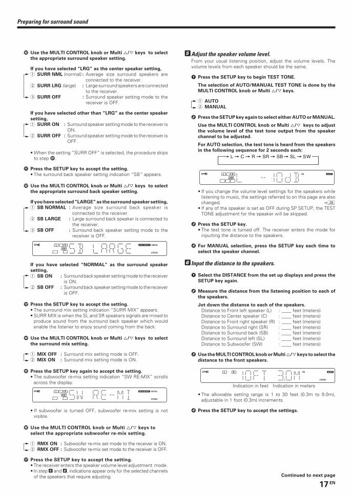
Preparing for surround sound
0 Use the MULTI CONTROL knob or Multi %/fi keys to select
the appropriate surround speaker setting.
If you have selected “LRG” as the center speaker setting,
1 SURR NML (normal) : Average size surround speakers areconnected to the receiver.
2 SURR LRG (large) : Large surround speakers are connectedto the receiver.
3 SURR OFF : Surround speaker setting mode to thereceiver is OFF.
If you have selected other than “LRG” as the center speaker
setting,
1 SURR ON : Surround speaker setting mode to the receiver isON.
2 SURR OFF : Surround speaker setting mode to the receiver isOFF.
• When the setting “SURR OFF” is selected, the procedure skipsto step %.
! Press the SETUP key to accept the setting.
• The surround back speaker setting indication “SB” appears.
@ Use the MULTI CONTROL knob or Multi %/fi keys to select
the appropriate surround back speaker setting.
If you have selected “LARGE” as the surround speaker setting,
1 SB NORMAL : Average size surround back speaker isconnected to the receiver.
2 SB LARGE : Large surround back speaker is connected tothe receiver.
3 SB OFF : Surround back speaker setting mode to thereceiver is OFF.
If you have selected “NORMAL” as the surround speaker
setting,
1 SB ON : Surround back speaker setting mode to the receiveris ON.
2 SB OFF : Surround back speaker setting mode to the receiveris OFF.
# Press the SETUP key to accept the setting.
• The surround mix setting indication “SURR MIX” appears.• SURR MIX is when the SL and SR speakers signals are mixed to
produce sound from the surround back speaker which wouldenable the listener to enjoy sound coming from the back.
$ Use the MULTI CONTROL knob or Multi %/fi keys to select
the surround mix setting.
1 MIX OFF : Surround mix setting mode is OFF.2 MIX ON : Surround mix setting mode is ON.
% Press the SETUP key again to accept the setting.
• The subwoofer re-mix setting indication “SW RE-MIX” scrollsacross the display.
• If subwoofer is turned OFF, subwoofer re-mix setting is notvisible.
^ Use the MULTI CONTROL knob or Multi %/fi keys to
select the appropriate subwoofer re-mix setting.
1 RMX ON : Subwoofer re-mix set mode to the receiver is ON.2 RMX OFF : Subwoofer re-mix set mode to the receiver is OFF.
& Press the SETUP key to accept the setting.
• The receiver enters the speaker volume level adjustment mode.• In step 5 and 6, indications appear only for the selected channels
of the speakers that require adjusting.
5Adjust the speaker volume level.From your usual listening position, adjust the volume levels. Thevolume levels from each speaker should be the same.
1 Press the SETUP key to begin TEST TONE.
The selection of AUTO/MANUAL TEST TONE is done by the
MULTI CONTROL knob or Multi %/fi keys.
1 AUTO
2 MANUAL
2 Press the SETUP key again to select either AUTO or MANUAL.
Use the MULTI CONTROL knob or Multi %/fi keys to adjust
the volume level of the test tone output from the speaker
channel to be adjusted.
For AUTO selection, the test tone is heard from the speakers
in the following sequence for 2 seconds each:
• If you change the volume level settings for the speakers whilelistening to music, the settings referred to on this page are alsochanged. §
• If any of the speaker is set as OFF during SP SETUP, the TESTTONE adjustment for the speaker will be skipped.
3 Press the SETUP key.
• The test tone is turned off. The receiver enters the mode forinputting the distance to the speakers.
4 For MANUAL selection, press the SETUP key each time to
select the speaker channel.
6Input the distance to the speakers.
1 Select the DISTANCE from the set up displays and press the
SETUP key again.
2 Measure the distance from the listening position to each of
the speakers.
Jot down the distance to each of the speakers.
Distance to Front left speaker (L) : ____ feet (meters)Distance to Center speaker (C) : ____ feet (meters)Distance to Front right speaker (R) : ____ feet (meters)Distance to Surround right (SR) : ____ feet (meters)Distance to Surround back (SB) : ____ feet (meters)Distance to Surround left (SL) : ____ feet (meters)Distance to Subwoofer (SW) : ____ feet (meters)
3 Use the MULTI CONTROL knob or Multi %/fi keys to select the
distance to the front speakers.
Indication in feet Indication in meters
• The allowable setting range is 1 to 30 feet (0.3m to 9.0m),adjustable in 1 foot (0.3m) increments.
4 Press the SETUP key to accept the settings.
Continued to next page
*5330/16-22/EN 1/23/03, 2:01 PM17
18 EN
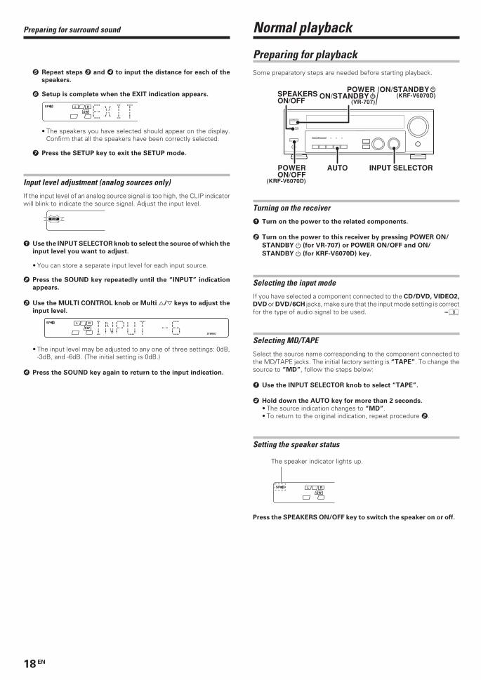
Normal playback
Preparing for playbackSome preparatory steps are needed before starting playback.
Turning on the receiver
1 Turn on the power to the related components.
2 Turn on the power to this receiver by pressing POWER ON/
STANDBY (for VR-707) or POWER ON/OFF and ON/
STANDBY (for KRF-V6070D) key.
Selecting the input mode
If you have selected a component connected to the CD/DVD, VIDEO2,
DVD or DVD/6CH jacks, make sure that the input mode setting is correctfor the type of audio signal to be used. 8
Selecting MD/TAPE
Select the source name corresponding to the component connected tothe MD/TAPE jacks. The initial factory setting is “TAPE”. To change thesource to “MD”, follow the steps below:
1 Use the INPUT SELECTOR knob to select “TAPE”.
2 Hold down the AUTO key for more than 2 seconds.
• The source indication changes to “MD”.• To return to the original indication, repeat procedure 2.
Setting the speaker status
Press the SPEAKERS ON/OFF key to switch the speaker on or off.
AUTO INPUT SELECTOR
(KRF-V6070D)
POWERON/OFF
SPEAKERS ON/OFF
ON/STANDBY(KRF-V6070D)
(VR-707)
POWERON/STANDBY
5 Repeat steps 3 and 4 to input the distance for each of the
speakers.
6 Setup is complete when the EXIT indication appears.
• The speakers you have selected should appear on the display.Confirm that all the speakers have been correctly selected.
7 Press the SETUP key to exit the SETUP mode.
Input level adjustment (analog sources only)
If the input level of an analog source signal is too high, the CLIP indicatorwill blink to indicate the source signal. Adjust the input level.
1 Use the INPUT SELECTOR knob to select the source of which the
input level you want to adjust.
• You can store a separate input level for each input source.
2 Press the SOUND key repeatedly until the “INPUT” indication
appears.
3 Use the MULTI CONTROL knob or Multi %/fi keys to adjust the
input level.
• The input level may be adjusted to any one of three settings: 0dB,-3dB, and -6dB. (The initial setting is 0dB.)
4 Press the SOUND key again to return to the input indication.
The speaker indicator lights up.
Preparing for surround sound
*5330/16-22/EN 1/21/03, 9:56 PM18
19 EN
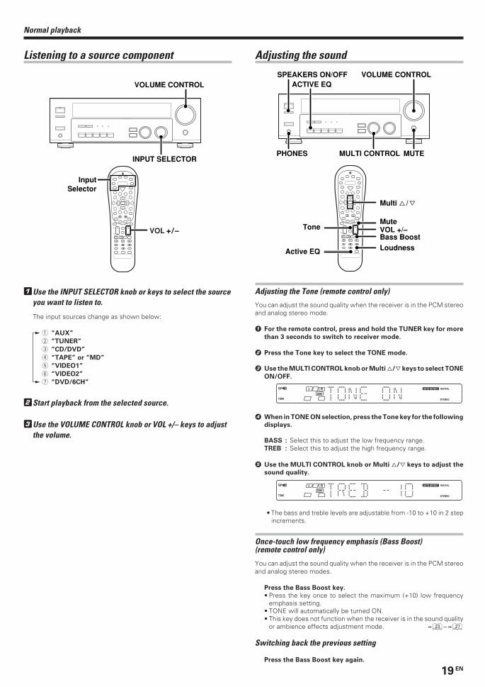
Listening to a source component
1Use the INPUT SELECTOR knob or keys to select the sourceyou want to listen to.
The input sources change as shown below:
1 “AUX”
2 “TUNER”
3 “CD/DVD”
4 “TAPE” or “MD”
5 “VIDEO1”
6 “VIDEO2”
7 “DVD/6CH”
2Start playback from the selected source.
3Use the VOLUME CONTROL knob or VOL +/– keys to adjustthe volume.
4
¢ + +
+
INPUT SELECTOR
VOLUME CONTROL
InputSelector
VOL
Normal playback
Adjusting the sound
Adjusting the Tone (remote control only)
You can adjust the sound quality when the receiver is in the PCM stereoand analog stereo mode.
1 For the remote control, press and hold the TUNER key for more
than 3 seconds to switch to receiver mode.
2 Press the Tone key to select the TONE mode.
3 Use the MULTI CONTROL knob or Multi %/fi keys to select TONE
ON/OFF.
4 When in TONE ON selection, press the Tone key for the following
displays.
BASS : Select this to adjust the low frequency range.TREB : Select this to adjust the high frequency range.
5 Use the MULTI CONTROL knob or Multi %/fi keys to adjust the
sound quality.
• The bass and treble levels are adjustable from -10 to +10 in 2 stepincrements.
Once-touch low frequency emphasis (Bass Boost)(remote control only)
You can adjust the sound quality when the receiver is in the PCM stereoand analog stereo modes.
Press the Bass Boost key.
• Press the key once to select the maximum (+10) low frequencyemphasis setting.
• TONE will automatically be turned ON.• This key does not function when the receiver is in the sound quality
or ambience effects adjustment mode. £~¶
Switching back the previous setting
Press the Bass Boost key again.
4
¢ +
–
+
–
– +
ACTIVE EQVOLUME CONTROL
PHONES MULTI CONTROL
SPEAKERS ON/OFF
MUTE
Loudness
ToneBass Boost
Active EQ
MuteVOL +/–
Multi % / fi
*5330/16-22/EN 1/21/03, 9:56 PM19
20 EN
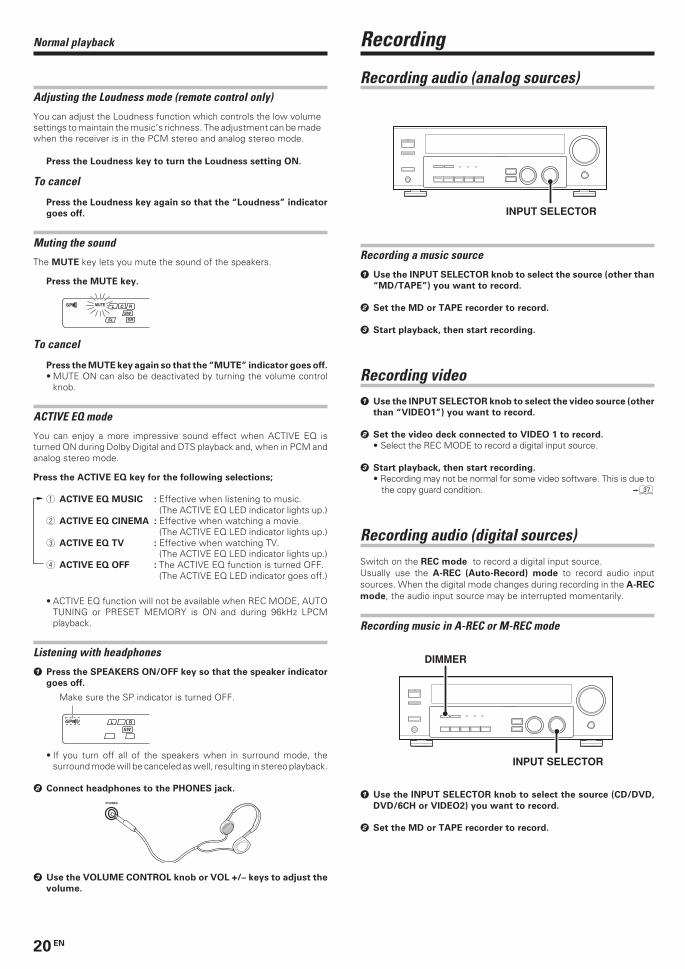
Recording audio (analog sources)
Recording a music source
1 Use the INPUT SELECTOR knob to select the source (other than
“MD/TAPE”) you want to record.
2 Set the MD or TAPE recorder to record.
3 Start playback, then start recording.
Recording video1 Use the INPUT SELECTOR knob to select the video source (other
than “VIDEO1”) you want to record.
2 Set the video deck connected to VIDEO 1 to record.
• Select the REC MODE to record a digital input source.
3 Start playback, then start recording.
• Recording may not be normal for some video software. This is due tothe copy guard condition. ‡
Recording audio (digital sources)Switch on the REC mode to record a digital input source.Usually use the A-REC (Auto-Record) mode to record audio inputsources. When the digital mode changes during recording in the A-REC
mode, the audio input source may be interrupted momentarily.
Recording music in A-REC or M-REC mode
INPUT SELECTOR
DIMMER
1 Use the INPUT SELECTOR knob to select the source (CD/DVD,
DVD/6CH or VIDEO2) you want to record.
2 Set the MD or TAPE recorder to record.
INPUT SELECTOR
Normal playback
Adjusting the Loudness mode (remote control only)
You can adjust the Loudness function which controls the low volumesettings to maintain the music’s richness. The adjustment can be madewhen the receiver is in the PCM stereo and analog stereo mode.
Press the Loudness key to turn the Loudness setting ON.
To cancel
Press the Loudness key again so that the “Loudness” indicator
goes off.
Muting the sound
The MUTE key lets you mute the sound of the speakers.
Press the MUTE key.
To cancel
Press the MUTE key again so that the “MUTE” indicator goes off.
• MUTE ON can also be deactivated by turning the volume controlknob.
ACTIVE EQ mode
You can enjoy a more impressive sound effect when ACTIVE EQ isturned ON during Dolby Digital and DTS playback and, when in PCM andanalog stereo mode.
Press the ACTIVE EQ key for the following selections;
1 ACTIVE EQ MUSIC : Effective when listening to music.(The ACTIVE EQ LED indicator lights up.)
2 ACTIVE EQ CINEMA : Effective when watching a movie.(The ACTIVE EQ LED indicator lights up.)
3 ACTIVE EQ TV : Effective when watching TV.(The ACTIVE EQ LED indicator lights up.)
4 ACTIVE EQ OFF : The ACTIVE EQ function is turned OFF.(The ACTIVE EQ LED indicator goes off.)
• ACTIVE EQ function will not be available when REC MODE, AUTOTUNING or PRESET MEMORY is ON and during 96kHz LPCMplayback.
Listening with headphones
1 Press the SPEAKERS ON/OFF key so that the speaker indicator
goes off.
• If you turn off all of the speakers when in surround mode, thesurround mode will be canceled as well, resulting in stereo playback.
2 Connect headphones to the PHONES jack.
PHONES
3 Use the VOLUME CONTROL knob or VOL +/– keys to adjust the
volume.
Make sure the SP indicator is turned OFF.
Recording
*5330/16-22/EN 1/21/03, 9:56 PM20
21 EN
Recording
3 Press and hold the DIMMER key for more than 2 seconds to select
the A-REC or M-REC mode during digital input.
1 Rec mode off : The digital input record mode is switched off.2 A-REC mode : The digital input signals (DTS, Dolby Digital,
or PCM) are identified automatically andconverted into stereo signals that are readyfor recording.
3 M-REC mode : The input signal type at the moment thismode is selected is held throughout thismode.
For A-REC mode:
For M-REC mode:
4 Start playback, then start recording.
• If the audio reproduction stops in the middle due to change in theinput signals, etc., press the DIMMER key.
Listening to radio broadcastsThe receiver can store up to 40 stations in the memory and recall themby one-touch operation.
Tuning radio stations
“AM” or “FM” indicatorappears in the display
“AUTO” indicator lightsup in the display.
1Use the INPUT SELECTOR knob or TUNER key to select thetuner.
2Use the BAND key to select the desired broadcast band.
Each press switches the band
as follows:
1 FM
2 AM
3Use the AUTO key to select the desired tuning method.
Each press switches the tuning method as follows:
1 AUTO lit (auto tuning)2 AUTO not lit (manual tuning)
• Normally, set to “AUTO” (auto tuning). If the radio waves are weakand there is a lot of interference, switch to manual tuning. (Withmanual tuning, stereo broadcasts will be received in monaural.)
4Use the MULTI CONTROL knob or Multi %/ fi keys, or Tune– 1 / + ¡ keys to select the station.
Auto tuning : The next station is tuned automatically.Manual tuning : Turn the knob (press the key) to select the desired
station.
Frequencydisplay
“TUNED” is displayedwhen a station is received.
“ST.” lights whena broadcast is beingreceived in stereo.
4
¢ + +
+
MULTI CONTROL
INPUT SELECTORBAND AUTO
TUNER
Auto
BandTune – 1 / + ¡
Multi % / fi
*5330/16-22/EN 1/21/03, 9:56 PM21
22 EN
Presetting radio stations manually
MULTI CONTROL
MEMORY
1Tune to the station you want to store.
2Press the MEMORY key while receiving the station.
3Use the MULTI CONTROL knob or Multi %/ fi keys to selectone of the station presets (1 – 40).
4Press the MEMORY key again to confirm the setting.
• Repeat steps 1, 2, 3, and 4 to store as many stations asnecessary.
• If you store a station at a previously used preset, the previous stationwill be replaced by the new one.
Receiving preset stations
4
¢ + +
+
TUNER
Numeric keys
1Press the TUNER key to select tuner as the source.
2Enter the number of the preset station you want to receive(up to “40”).
Press the numeric keys in the following order:
For “15”, press ................................ 0,5
For “20”, press ................................ 0,0,)
• If you make a mistake entering a two digit number, press the +10key repeatedly to return to the original display and start again.
Receiving preset stations in order (P.Call)
4
¢ + +
+
TUNER
P.Call @ / #
1Press the TUNER key to select tuner as the source.
2Use the P.Call @¥# keys to select the desired station.
• Each time you press the key, another preset station is received inorder.
Pressing the P.Call # does the following:
Pressing the P.Call @ does the following:
Holding down the P.Call # or @ key, lets you skip through the
presets, receiving each preset station at 0.5 second intervals.
Listening to radio broadcasts
Proceed to step 3 within 5 seconds.
(If more than 5 seconds elapse, press the MEMORY key again).
Blinks for 5 seconds Lights for 5 seconds
*5330/16-22/EN 1/21/03, 9:56 PM22
23 EN
Ambience effects
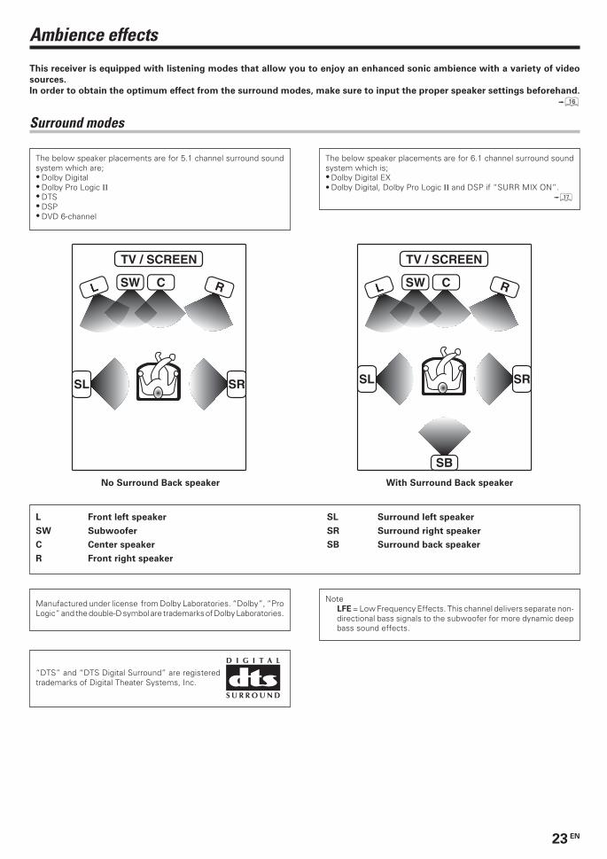
This receiver is equipped with listening modes that allow you to enjoy an enhanced sonic ambience with a variety of video
sources.
In order to obtain the optimum effect from the surround modes, make sure to input the proper speaker settings beforehand.
^
Surround modes
Manufactured under license from Dolby Laboratories. “Dolby”, “ProLogic” and the double-D symbol are trademarks of Dolby Laboratories.
“DTS” and “DTS Digital Surround” are registeredtrademarks of Digital Theater Systems, Inc.
SRSL
CL RSW
TV / SCREEN
No Surround Back speaker With Surround Back speaker
L Front left speaker SL Surround left speaker
SW Subwoofer SR Surround right speaker
C Center speaker SB Surround back speaker
R Front right speaker
The below speaker placements are for 5.1 channel surround soundsystem which are;• Dolby Digital• Dolby Pro Logic II• DTS• DSP• DVD 6-channel
SB
SRSL
CL RSW
TV / SCREEN
NoteLFE = Low Frequency Effects. This channel delivers separate non-directional bass signals to the subwoofer for more dynamic deepbass sound effects.
The below speaker placements are for 6.1 channel surround soundsystem which is;• Dolby Digital EX• Dolby Digital, Dolby Pro Logic II and DSP if “SURR MIX ON”.
&
*5330/23-27/EN 1/21/03, 9:53 PM23
24 EN
Dolby DigitalThe Dolby Digital surround format lets you enjoy up to 5.1 channelsof digital surround sound from Dolby Digital program sources (such
as Laserdisc or DVD software marked ). Compared withprevious Dolby surround, Dolby Digital provides even better soundquality, greater spatial accuracy, and improved dynamic range.
Although a full set of speakers (front left, right, and center, surroundleft and right, and a subwoofer) is required for true 5.1 channel DolbyDigital surround sound, this receiver lets you enjoy Dolby Digital (andDolby Surround) program sources, even if you connect only the frontspeakers.
Dolby Digital EXDolby Digital EX is an extension of Dolby Digital technology, DolbyDigital EX creates six full-bandwidth output channels from 6.1-channel sources. This is done using a matrix decoder that derivesthree surround channels from the two in the original recording.This is achieved by using three different surround signals, surroundleft, surround right, and surround back, each driving its own array ofspeakers. Think of it as adding a center channel for the rear speakers,which give more diffuse and natural surround effect, even if youwanted the ability to completely encircle the audience with sound,positioning sound effects exactly where they would be heard in reallife. For best results, Dolby Digital EX should be used with moviesoundtracks recorded with Dolby Digital Surround EX which containa digital flag that will automatically activate this feature. However, fortitles released prior to late 2001, this feature has to be activatedmanually.
Although a full set of speakers (front left, right, and center, surroundleft and right, surround back and a subwoofer) is required for true 6.1channel Dolby Digital Surround EX sound, this receiver lets you enjoyDolby Digital (and Dolby Surround) program sources, even if youconnect only the front speakers.
Although only Dolby Digital soundtracks incorporate a separate lowfrequency channel, connecting a subwoofer will also improve deepbass performance in the other surround modes.
The indication “LFE” appears in the display when a signal is beinginput for this channel. £
Dolby PRO LOGIC IIDolby Pro Logic II was designed specifically to provide a new senseof spatiality, directionality and articulation of sounds from DolbySurround encoded sources (such as video and Laserdisc softwaremarked ). This is achieved with an intelligent, built-infeedback logic design, a matrix surround decoding and the decodingof stereo, full bandwidth surround outputs. The PRO LOGIC II modesprogrammed into this receiver are “MOVIE”, “MUSIC” and “PROLOGIC”. The “MOVIE” mode of the PRO LOGIC II has presetcharacteristics to produce a calibrated, high-level surround soundplayback while the “MUSIC” mode has user-adjustable characteristicsto offer the three optional controls, like “Dimension”, “CenterWidth” and “Panorama” modes to allow optimization of thesoundfields as desired. The “Dimension” control allows the user togradually adjust the soundfield either towards the front or towardsthe rear; the “Center Width” control allows various adjustment of theleft-center-right speakers’ balance; the “Panorama” mode extendsthe front stereo image to include the surround speakers for anexciting “wraparound” effect with side wall imaging.
Ambience effects
DVD 6-channel modeUsing a DVD player or the like equipped with six (5.1) output channelsand the receiver, you can enjoy multi-channel encoded DVD sourcematerial in all its splendor. Since the source signals are digital andeach channel is input independently, the resulting sound quality,sense of spaciousness, and dynamic range are superb.
The indication “LFE” appears in the display during DVD 6-channelmode selection. £
DSP modeThe DSP mode lets you add the atmosphere of a live concert or hallto almost any type of program source. These modes are particularlyeffective when used with stereo program sources, like CD, television,and FM radio. You might enjoy trying the ARENA, JAZZ CLUB,THEATER, STADIUM or DISCO mode the next time you watch aconcert or sporting event!
What's DSP?DSP stands for Digital Signal Processor.The way a sound is heard in an actual environment depends on avariety of different factors. One of the most important is reverberation(the act of decaying elements of sound echoing in various places).The DSP modes produce the feeling of presence by using the DSP tocreate reverberation, without spoiling the sound quality of the originalsignal.
DTS modeThe DTS multi-channel audio format is available on CD, LD and DVDsoftware. DTS is a strictly digital format and cannot be decodedinside most CD, LD or DVD players. For this reason, if you attemptto listen to DTS encoded software through the analog output of yournew CD, LD or DVD player, you will experience digital noise in mostcases. This noise can be quite loud if the analog output is connecteddirectly to a high power amplification system. Proper measures forplaying the digital output as described below should be taken toavoid this situation. To enjoy DTS Digital Surround playback, anexternal 5.1 channel DTS Digital Surround decoder system or anamplifier with a built-in DTS Digital Surround decoder must beconnected to the digital output (S/P DIF, AES/EBU or TosLink) of aCD, LD or DVD player.All models are incorporated with the DTS decoder.
DTS has a .1 or LFE channel.The indication “LFE” appears in the display when a signal is beinginput for this channel. £
*5330/23-27/EN 1/21/03, 9:53 PM24
25 EN
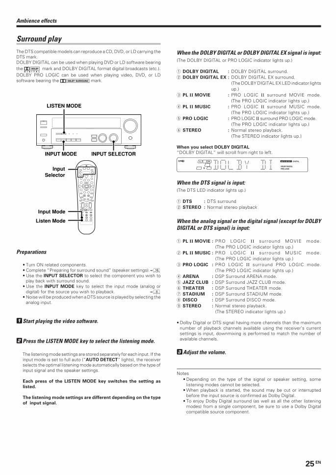
Surround playThe DTS compatible models can reproduce a CD, DVD, or LD carrying theDTS mark.DOLBY DIGITAL can be used when playing DVD or LD software bearingthe mark and DOLBY DIGITAL format digital broadcasts (etc.).DOLBY PRO LOGIC can be used when playing video, DVD, or LDsoftware bearing the mark.
4
¢ + +
+
INPUT SELECTOR
LISTEN MODE
INPUT MODE
Input Mode
Listen Mode
InputSelector
Preparations
• Turn ON related components.• Complete “Preparing for surround sound” (speaker settings).^• Use the INPUT SELECTOR to select the component you wish to
play back with surround sound.• Use the INPUT MODE key to select the input mode (analog or
digital) for the source you wish to playback. 8• Noise will be produced when a DTS source is played by selecting the
analog input.
1Start playing the video software.
2Press the LISTEN MODE key to select the listening mode.
The listening mode settings are stored separately for each input. If theinput mode is set to full auto (“AUTO DETECT” lights), the receiverselects the optimal listening mode automatically based on the type ofinput signal and the speaker settings.
Each press of the LISTEN MODE key switches the setting as
listed.
The listening mode settings are different depending on the type
of input signal.
When the DOLBY DIGITAL or DOLBY DIGITAL EX signal is input:(The DOLBY DIGITAL or PRO LOGIC indicator lights up.)
1 DOLBY DIGITAL : DOLBY DIGITAL surround.2 DOLBY DIGITAL EX : DOLBY DIGITAL EX surround.
(The DOLBY DIGITAL EX LED indicator lightsup.)
3 PL II MOVIE : PRO LOGIC II surround MOVIE mode.(The PRO LOGIC indicator lights up.)
4 PL II MUSIC : PRO LOGIC II surround MUSIC mode.(The PRO LOGIC indicator lights up.)
5 PRO LOGIC : PRO LOGIC II surround PRO LOGIC mode.(The PRO LOGIC indicator lights up.)
6 STEREO : Normal stereo playback.(The STEREO indicator lights up.)
When you select DOLBY DIGITAL
“DOLBY DIGITAL” will scroll from right to left.
When the DTS signal is input:(The DTS LED indicator lights up.)
1 DTS : DTS surround2 STEREO : Normal stereo playback
When the analog signal or the digital signal (except for DOLBYDIGITAL or DTS signal) is input:
1 PL II MOVIE : PRO LOGIC II surround MOVIE mode.(The PRO LOGIC indicator lights up.)
2 PL II MUSIC : PRO LOGIC II surround MUSIC mode.(The PRO LOGIC indicator lights up.)
3 PRO LOGIC : PRO LOGIC II surround PRO LOGIC mode.(The PRO LOGIC indicator lights up.)
4 ARENA : DSP Surround ARENA mode.5 JAZZ CLUB : DSP Surround JAZZ CLUB mode.6 THEATER : DSP Surround THEATER mode.7 STADIUM : DSP Surround STADIUM mode.8 DISCO : DSP Surround DISCO mode.9 STEREO : Normal stereo playback.
(The STEREO indicator lights up.)
• Dolby Digital or DTS signal having more channels than the maximumnumber of playback channels available using the receiver’s currentsettings is input, downmixing is performed to match the number ofavailable channels.
3Adjust the volume.
Notes• Depending on the type of the signal or speaker setting, some
listening modes cannot be selected.• When playback is started, the sound may be cut or interrupted
before the input source is confirmed as Dolby Digital.• To enjoy Dolby Digital surround (as well as all the other listening
modes) from a single component, be sure to use a Dolby Digitalcompatible source component.
Ambience effects
*5330/23-27/EN 1/21/03, 9:54 PM25
26 EN
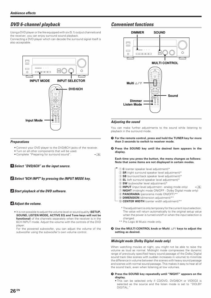
DVD 6-channel playbackUsing a DVD player or the like equipped with six (5.1) output channels andthe receiver, you can enjoy surround sound playback.Connecting a DVD player which can decode the surround signal itself isalso acceptable.
4
¢ + +
+
INPUT SELECTORINPUT MODE
DVD/6CH
Input Mode
Preparations
• Connect your DVD player to the DVD/6CH jacks of the receiver.• Turn on all other components that will be used.• Complete “Preparing for surround sound”. ^
1Select “DVD/6CH” as the input source.
2Select "6CH INPT" by pressing the INPUT MODE key.
3Start playback of the DVD software.
4Adjust the volume.
• It is not possible to adjust the volume level or sound quality (SETUP,
SOUND, LISTEN MODE, ACTIVE EQ and Tone keys will not be
functional) of the channels separately when the receiver is in the6CH INPUT mode. Adjust the volume with the controls of the DVDplayer.For the powered subwoofer, you can adjust the volume of thesubwoofer using the subwoofer’s own volume control.
Convenient functions
Adjusting the sound
You can make further adjustments to the sound while listening toplayback in the surround mode.
1 For the remote control, press and hold the TUNER key for more
than 3 seconds to switch to receiver mode.
2 Press the SOUND key until the desired item appears in the
display.
Each time you press the button, the menu changes as follows:
Note that some items are not displayed in certain modes.
1 C (center speaker level adjustment)*2 SR (right surround speaker level adjustment)*3 SB (surround back speaker level adjustment)*4 SL (left surround speaker level adjustment)*5 SW (subwoofer level adjustment)*6 INPUT (input level adjustment - analog mode only) *7 NIGHT (midnight mode ON/OFF - Dolby Digital mode only)8 PANORAMA (panorama mode ON/OFF)**9 DIMENSION (dimension adjustment)**0 CENTER WIDTH (center width adjustment)**
* The adjustment is only temporary for the current input selection.The value will return automatically to the original setup valuewhen the power is turned on/off or when the input selection ischanged.
** Pro Logic II Music mode only.
3 Use the MULTI CONTROL knob or Multi %/fi keys to adjust the
setting as desired.
Midnight mode (Dolby Digital mode only)
When watching movies at night, you might not be able to raise thevolume as loud as normal. Midnight mode compresses the dynamicrange of previously specified heavy sound passage of the Dolby Digitalsound track (like scenes with sudden increases in volume) to minimizethe difference in volume between the scenes with heavy sound passageand scenes with normal sound passage. This makes it easy to hear all ofthe sound track, even when listening at low volumes.
1 Press the SOUND key repeatedly until “NIGHT” appears on the
display.
• This can be selected only if CD/DVD, DVD/6CH or VIDEO2 isselected as the source and the listen mode is set to “DOLBYDIGITAL.”
4
¢ + +
+
MULTI CONTROL
DIMMER SOUND
Sound
Listen ModeDimmer
Multi % / fi
Ambience effects
*5330/23-27/EN 1/21/03, 9:54 PM26
27 EN
2 Use the MULTI CONTROL knob or Multi %/fi keys to select the
ON or OFF setting.
• Some Dolby Digital software may not be compatible with theMidnight mode.
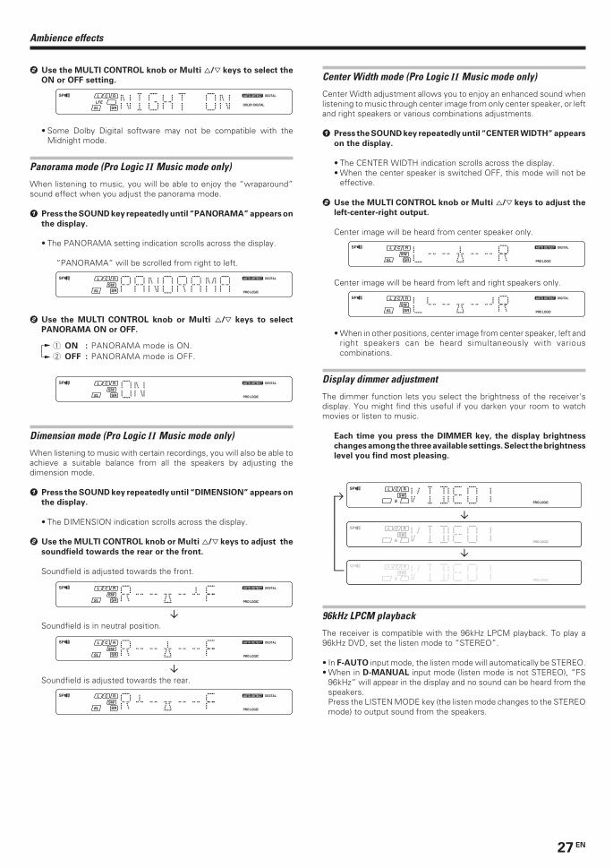
Panorama mode (Pro Logic II Music mode only)
When listening to music, you will be able to enjoy the “wraparound”sound effect when you adjust the panorama mode.
1 Press the SOUND key repeatedly until “PANORAMA” appears on
the display.
• The PANORAMA setting indication scrolls across the display.
“PANORAMA” will be scrolled from right to left.
2 Use the MULTI CONTROL knob or Multi %/fi keys to select
PANORAMA ON or OFF.
1 ON : PANORAMA mode is ON.2 OFF : PANORAMA mode is OFF.
Dimension mode (Pro Logic II Music mode only)
When listening to music with certain recordings, you will also be able toachieve a suitable balance from all the speakers by adjusting thedimension mode.
1 Press the SOUND key repeatedly until “DIMENSION” appears on
the display.
• The DIMENSION indication scrolls across the display.
2 Use the MULTI CONTROL knob or Multi %/fi keys to adjust the
soundfield towards the rear or the front.
Soundfield is adjusted towards the front.
Soundfield is in neutral position.
Soundfield is adjusted towards the rear.
Center Width mode (Pro Logic II Music mode only)
Center Width adjustment allows you to enjoy an enhanced sound whenlistening to music through center image from only center speaker, or leftand right speakers or various combinations adjustments.
1 Press the SOUND key repeatedly until “CENTER WIDTH” appears
on the display.
• The CENTER WIDTH indication scrolls across the display.• When the center speaker is switched OFF, this mode will not be
effective.
2 Use the MULTI CONTROL knob or Multi %/fi keys to adjust the
left-center-right output.
Center image will be heard from center speaker only.
Center image will be heard from left and right speakers only.
• When in other positions, center image from center speaker, left andright speakers can be heard simultaneously with variouscombinations.
Display dimmer adjustment
The dimmer function lets you select the brightness of the receiver'sdisplay. You might find this useful if you darken your room to watchmovies or listen to music.
Each time you press the DIMMER key, the display brightness
changes among the three available settings. Select the brightness
level you find most pleasing.
96kHz LPCM playback
The receiver is compatible with the 96kHz LPCM playback. To play a96kHz DVD, set the listen mode to “STEREO”.
• In F-AUTO input mode, the listen mode will automatically be STEREO.• When in D-MANUAL input mode (listen mode is not STEREO), “FS
96kHz” will appear in the display and no sound can be heard from thespeakers.Press the LISTEN MODE key (the listen mode changes to the STEREOmode) to output sound from the speakers.
Ambience effects
*5330/23-27/EN 1/21/03, 9:54 PM27
28 EN
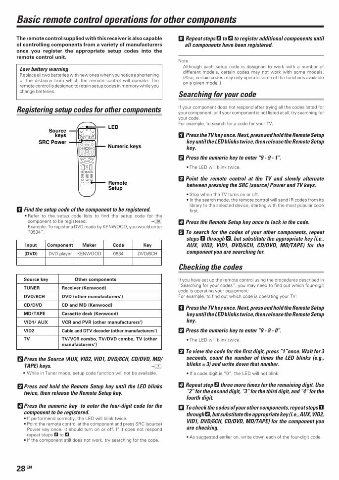
4
¢ + +
+
Sourcekeys
Numeric keys
LED
Remote Setup
SRC Power
The remote control supplied with this receiver is also capable
of controlling components from a variety of manufacturers
once you register the appropriate setup codes into the
remote control unit.
Low battery warningReplace all two batteries with new ones when you notice a shorteningof the distance from which the remote control will operate. Theremote control is designed to retain setup codes in memory while youchange batteries.
Registering setup codes for other components
1 Find the setup code of the component to be registered.• Refer to the setup code lists to find the setup code for the
component to be registered. ºExample: To register a DVD made by KENWOOD, you would enter“0534”.
Input Component Maker Code Key
(DVD) DVD player KENWOOD 0534 DVD/6CH
Source key Other components
TUNER Receiver (Kenwood)
DVD/6CH DVD (other manufacturers’)
CD/DVD CD and MD (Kenwood)
MD/TAPE Cassette deck (Kenwood)
VID1/ AUX VCR and PVR (other manufacturers’)
VID2 Cable and DTV decoder (other manufacturers’)
TV TV/VCR combo, TV/DVD combo, TV (other
manufacturers’)
2Press the Source (AUX, VID2, VID1, DVD/6CH, CD/DVD, MD/TAPE) keys. 7
• While in Tuner mode, setup code function will not be available.
3Press and hold the Remote Setup key until the LED blinkstwice, then release the Remote Setup key.
4Press the numeric key to enter the four-digit code for thecomponent to be registered.• If performend correctly, the LED will blink twice.• Point the remote control at the component and press SRC (source)
Power key once. It should turn on or off. If it does not respondrepeat steps 2 to 4.
• If the component still does not work, try searching for the code.
5 Repeat steps 2 to 4 to register additional components untilall components have been registered.
NoteAlthough each setup code is designed to work with a number ofdifferent models, certain codes may not work with some models.(Also, certain codes may only operate some of the functions availableon a given model.)
Searching for your codeIf your component does not respond after trying all the codes listed foryour component, or if your component is not listed at all, try searching foryour code.For example, to search for a code for your TV.
1 Press the TV key once. Next, press and hold the Remote Setupkey until the LED blinks twice, then release the Remote Setupkey.
2 Press the numeric key to enter “9 - 9 - 1”.
• The LED will blink twice.
3 Point the remote control at the TV and slowly alternatebetween pressing the SRC (source) Power and TV keys.
• Stop when the TV turns on or off.• In the search mode, the remote control will send IR codes from its
library to the selected device, starting with the most popular codefirst.
4 Press the Remote Setup key once to lock in the code.
5 To search for the codes of your other components, repeatsteps 1 through 4, but substitute the appropriate key (i.e.,AUX, VID2, VID1, DVD/6CH, CD/DVD, MD/TAPE) for thecomponent you are searching for.
Checking the codesIf you have set up the remote control using the procedures described in“Searching for your codes”, you may need to find out which four-digitcode is operating your equipment:For example, to find out which code is operating your TV:
1 Press the TV key once. Next, press and hold the Remote Setupkey until the LED blinks twice, then release the Remote Setupkey.
2 Press the numeric key to enter “9 - 9 - 0”.
• The LED will blink twice.
3 To view the code for the first digit, press “1”once. Wait for 3seconds, count the number of times the LED blinks (e.g.,blinks = 3) and write down that number.
• If a code digit is “0”, the LED will not blink.
4 Repeat step 3 three more times for the remaining digit. Use“2” for the second digit, “3” for the third digit, and “4” for thefourth digit.
5 To check the codes of your other components, repeat steps 1through 4, but substitute the appropriate key (i.e., AUX, VID2,VID1, DVD/6CH, CD/DVD, MD/TAPE) for the component youare checking.
• As suggested earlier on, write down each of the four-digit code.
Basic remote control operations for other components
*5330/28-29/EN 1/21/03, 9:57 PM28
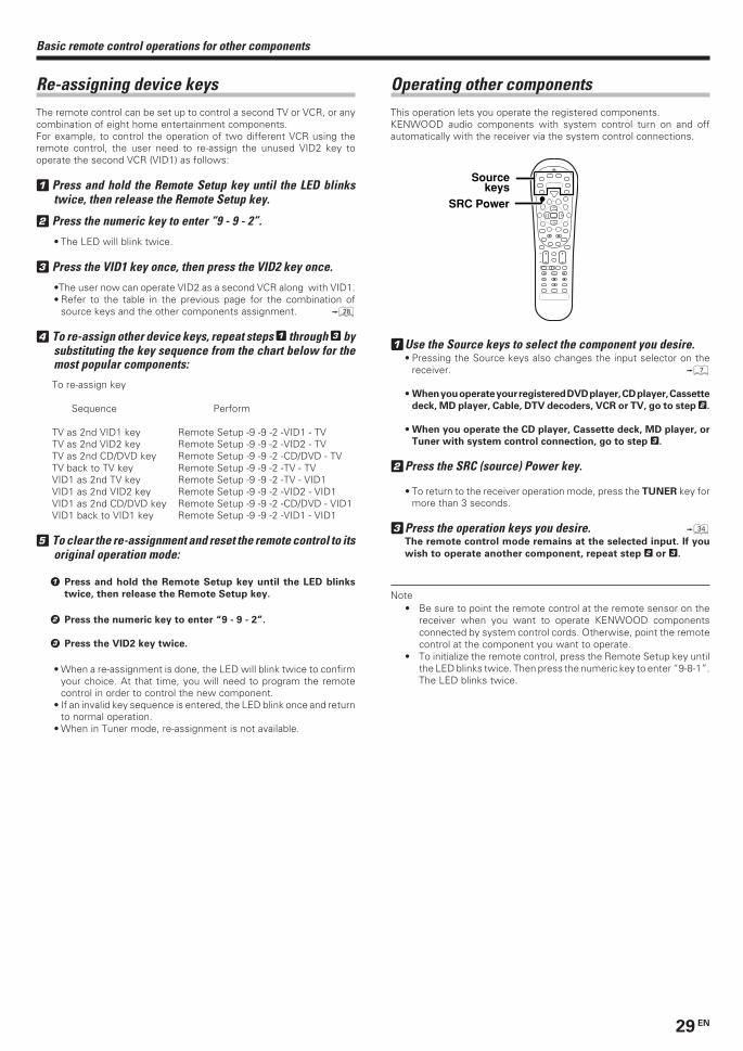
29 EN
Basic remote control operations for other components
Re-assigning device keysThe remote control can be set up to control a second TV or VCR, or anycombination of eight home entertainment components.For example, to control the operation of two different VCR using theremote control, the user need to re-assign the unused VID2 key tooperate the second VCR (VID1) as follows:
1 Press and hold the Remote Setup key until the LED blinkstwice, then release the Remote Setup key.
2 Press the numeric key to enter “9 - 9 - 2”.
• The LED will blink twice.
3 Press the VID1 key once, then press the VID2 key once.
•The user now can operate VID2 as a second VCR along with VID1.• Refer to the table in the previous page for the combination of
source keys and the other components assignment. •
4 To re-assign other device keys, repeat steps 1 through 3 bysubstituting the key sequence from the chart below for themost popular components:
To re-assign key
Sequence Perform
TV as 2nd VID1 key Remote Setup -9 -9 -2 -VID1 - TVTV as 2nd VID2 key Remote Setup -9 -9 -2 -VID2 - TVTV as 2nd CD/DVD key Remote Setup -9 -9 -2 -CD/DVD - TVTV back to TV key Remote Setup -9 -9 -2 -TV - TVVID1 as 2nd TV key Remote Setup -9 -9 -2 -TV - VID1VID1 as 2nd VID2 key Remote Setup -9 -9 -2 -VID2 - VID1VID1 as 2nd CD/DVD key Remote Setup -9 -9 -2 -CD/DVD - VID1VID1 back to VID1 key Remote Setup -9 -9 -2 -VID1 - VID1
5 To clear the re-assignment and reset the remote control to itsoriginal operation mode:
1 Press and hold the Remote Setup key until the LED blinks
twice, then release the Remote Setup key.
2 Press the numeric key to enter “9 - 9 - 2”.
3 Press the VID2 key twice.
• When a re-assignment is done, the LED will blink twice to confirmyour choice. At that time, you will need to program the remotecontrol in order to control the new component.
• If an invalid key sequence is entered, the LED blink once and returnto normal operation.
• When in Tuner mode, re-assignment is not available.
Operating other componentsThis operation lets you operate the registered components.KENWOOD audio components with system control turn on and offautomatically with the receiver via the system control connections.
1Use the Source keys to select the component you desire.• Pressing the Source keys also changes the input selector on the
receiver. 7
• When you operate your registered DVD player, CD player, Cassette
deck, MD player, Cable, DTV decoders, VCR or TV, go to step 2.
• When you operate the CD player, Cassette deck, MD player, or
Tuner with system control connection, go to step 3.
2Press the SRC (source) Power key.
• To return to the receiver operation mode, press the TUNER key formore than 3 seconds.
3Press the operation keys you desire. ›The remote control mode remains at the selected input. If you
wish to operate another component, repeat step 2 or 3.
Note• Be sure to point the remote control at the remote sensor on the
receiver when you want to operate KENWOOD componentsconnected by system control cords. Otherwise, point the remotecontrol at the component you want to operate.
• To initialize the remote control, press the Remote Setup key untilthe LED blinks twice. Then press the numeric key to enter “9-8-1”.The LED blinks twice.
4
¢ + +
+
SRC Power
Sourcekeys
*5330/28-29/EN 1/21/03, 9:57 PM29
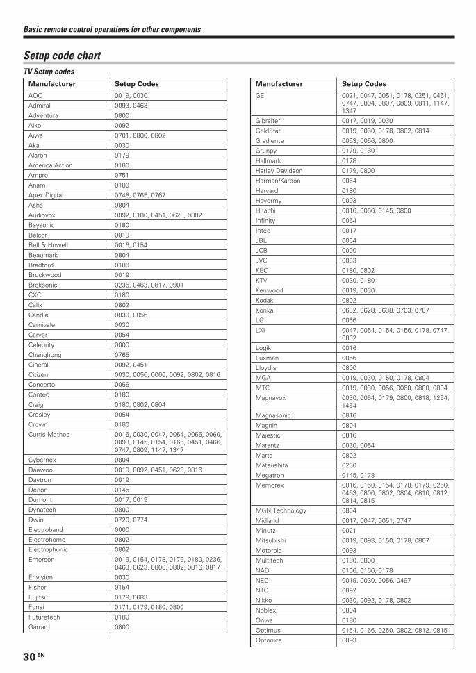
30 EN
Basic remote control operations for other components
Manufacturer Setup Codes
GE 0021, 0047, 0051, 0178, 0251, 0451,0747, 0804, 0807, 0809, 0811, 1147,1347
Gibralter 0017, 0019, 0030
GoldStar 0019, 0030, 0178, 0802, 0814
Gradiente 0053, 0056, 0800
Grunpy 0179, 0180
Hallmark 0178
Harley Davidson 0179, 0800
Harman/Kardon 0054
Harvard 0180
Havermy 0093
Hitachi 0016, 0056, 0145, 0800
Infinity 0054
Inteq 0017
JBL 0054
JCB 0000
JVC 0053
KEC 0180, 0802
KTV 0030, 0180
Kenwood 0019, 0030
Kodak 0802
Konka 0632, 0628, 0638, 0703, 0707
LG 0056
LXI 0047, 0054, 0154, 0156, 0178, 0747,0802
Logik 0016
Luxman 0056
Lloyd’s 0800
MGA 0019, 0030, 0150, 0178, 0804
MTC 0019, 0030, 0056, 0060, 0800, 0804
Magnavox 0030, 0054, 0179, 0800, 0818, 1254,1454
Magnasonic 0816
Magnin 0804
Majestic 0016
Marantz 0030, 0054
Marta 0802
Matsushita 0250
Megatron 0145, 0178
Memorex 0016, 0150, 0154, 0178, 0179, 0250,0463, 0800, 0802, 0804, 0810, 0812,0814, 0815
MGN Technology 0804
Midland 0017, 0047, 0051, 0747
Minutz 0021
Mitsubishi 0019, 0093, 0150, 0178, 0807
Motorola 0093
Multitech 0180, 0800
NAD 0156, 0166, 0178
NEC 0019, 0030, 0056, 0497
NTC 0092
Nikko 0030, 0092, 0178, 0802
Noblex 0804
Onwa 0180
Optimus 0154, 0166, 0250, 0802, 0812, 0815
Optonica 0093
Setup code chartTV Setup codes
Manufacturer Setup Codes
AOC 0019, 0030
Admiral 0093, 0463
Adventura 0800
Aiko 0092
Aiwa 0701, 0800, 0802
Akai 0030
Alaron 0179
America Action 0180
Ampro 0751
Anam 0180
Apex Digital 0748, 0765, 0767
Asha 0804
Audiovox 0092, 0180, 0451, 0623, 0802
Baysonic 0180
Belcor 0019
Bell & Howell 0016, 0154
Beaumark 0804
Bradford 0180
Brockwood 0019
Broksonic 0236, 0463, 0817, 0901
CXC 0180
Calix 0802
Candle 0030, 0056
Carnivale 0030
Carver 0054
Celebrity 0000
Changhong 0765
Cineral 0092, 0451
Citizen 0030, 0056, 0060, 0092, 0802, 0816
Concerto 0056
Contec 0180
Craig 0180, 0802, 0804
Crosley 0054
Crown 0180
Curtis Mathes 0016, 0030, 0047, 0054, 0056, 0060,0093, 0145, 0154, 0166, 0451, 0466,0747, 0809, 1147, 1347
Cybernex 0804
Daewoo 0019, 0092, 0451, 0623, 0816
Daytron 0019
Denon 0145
Dumont 0017, 0019
Dynatech 0800
Dwin 0720, 0774
Electroband 0000
Electrohome 0802
Electrophonic 0802
Emerson 0019, 0154, 0178, 0179, 0180, 0236,0463, 0623, 0800, 0802, 0816, 0817
Envision 0030
Fisher 0154
Fujitsu 0179, 0683
Funai 0171, 0179, 0180, 0800
Futuretech 0180
Garrard 0800
*5330/30-33/EN 1/21/03, 9:55 PM30
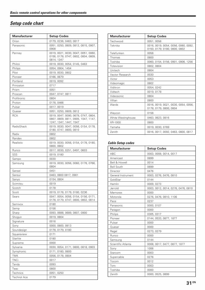
31 EN
Manufacturer Setup Codes
Orion 0179, 0236, 0463, 0817
Panasonic 0051, 0250, 0809, 0812, 0815, 0907,0908
Penney 0019, 0021, 0030, 0047, 0051, 0060,0156, 0178, 0747, 0802, 0804, 0809,0814, 1347
Philco 0019, 0030, 0054, 0145, 0463
Philips 0054, 0904, 1454
Pilot 0019, 0030, 0802
Pioneer 0166, 0679
Portland 0019, 0092
Princeton 0717
Prism 0051
Proscan 0047, 0747, 0811
Profitronic 0804
Proton 0178, 0466
Pulsar 0017, 0019
Quasar 0051, 0250, 0809, 0812
RCA 0019, 0047, 0090, 0679, 0747, 0804,0807, 0809, 0811, 0905, 1047, 1147,1247, 1347, 1447, 1547
RadioShack 0019, 0030, 0047, 0056, 0154, 0178,0180, 0747, 0800, 0810
Radix 0802
Randex 0802
Realistic 0019, 0030, 0056, 0154, 0178, 0180,0800, 0802
Runco 0017, 0030, 0251, 0497, 0603
SSS 0019, 0180
Sampo 0030
Samsung 0019, 0030, 0056, 0060, 0178, 0766,0804
Sansei 0451
Sansui 0463, 0800 0817, 0901
Sanyo 0154, 0804
Scimitsu 0019
Scotch 0178
Scott 0019, 0178, 0179, 0180, 0236
Sears 0047, 0054, 0056, 0154, 0156, 0171,0178, 0179, 0747, 0800, 0802, 0814
Semivox 0180
Semp 0156
Sharp 0093, 0688, 0689, 0807, 0900
Shogun 0019, 0804
Signature 0016
Sony 0000, 0800, 0813
Soundesign 0178, 0179, 0180
Squareview 0171
Starlite 0180
Supreme 0000
Sylvania 0030, 0054, 0171, 0800, 0818, 0903
Symphonic 0171, 0180, 0800
TMK 0056, 0178, 0804
TNCi 0017
Tandy 0093
Teac 0800
Technics 0051, 0250
Technol Ace 0179
Manufacturer Setup Codes
Techwood 0051, 0056
Teknika 0016, 0019, 0054, 0056, 0060, 0092,0150, 0179, 0180, 0800, 0802
Telefunken 0056
Thomas 0800
Toshiba 0060, 0154, 0156, 0901, 0906, 1256
Totevision 0802, 0804
Unitech 0804
Vector Research 0030
Victor 0053
Videomagic 0802
Vidikron 0054, 0242
Vidtech 0019, 0178
Videosonic 0804
Villian 0800
Wards 0016, 0019, 0021, 0030, 0054, 0056,0178, 0179, 0800, 0804
Waycon 0156
White Westinghouse 0463, 0623, 0816
XR-1000 0800
Yamaha 0019, 0030, 0769
Zenith 0016, 0017, 0092, 0463, 0800, 0817
Basic remote control operations for other components
Setup code chart
Cable Setup codes
Manufacturer Setup Codes
ABC 0003, 0008, 0014, 0017
Americast 0899
Bell & Howell 0014
Bell South 0899
Director 0476
General Instrument 0003, 0276, 0476, 0810
GoldStar 0144
Hamlin 0009, 0273
Jerrold 0003, 0012, 0014, 0276, 0476, 0810
Memorex 0000
Motorola 0276, 0476, 0810, 1106
Pace 0237
Panasonic 0000, 0107
Paragon 0000
Philips 0305, 0317
Pioneer 0144, 0533, 0877, 1877
Pulsar 0000
Quasar 0000
Regal 0273, 0279
Runco 0000
Samsung 0144
Scientific Atlanta 0008, 0017, 0477, 0877, 1877
Sony 1006
Starcom 0003
Supercable 0276
Tocom 0012
Torx 0003
Toshiba 0000
Zenith 0000, 0525, 0899
*5330/30-33/EN 1/21/03, 9:55 PM31
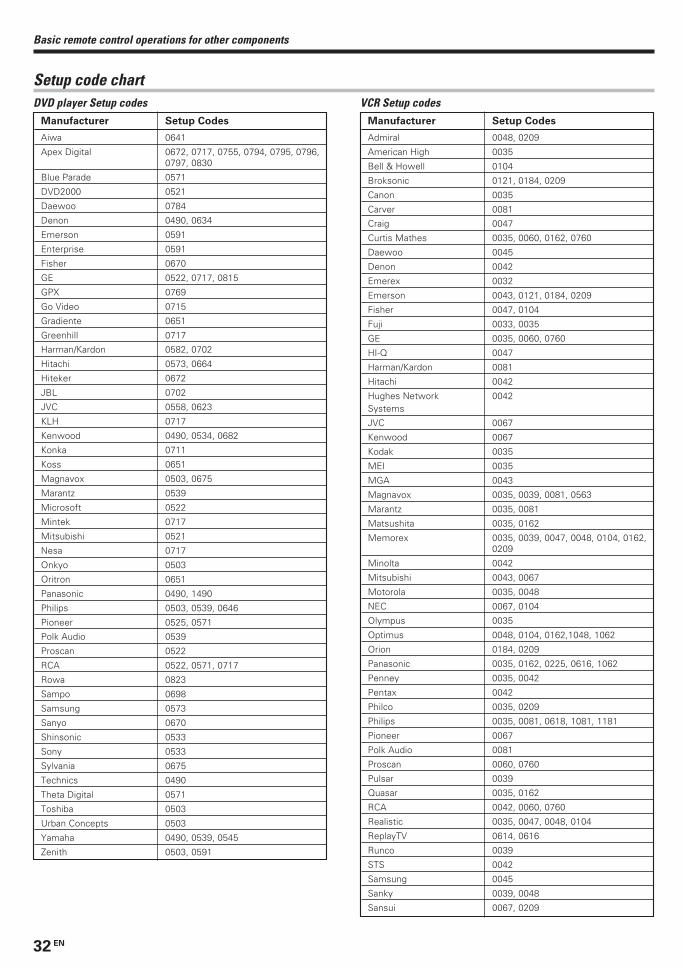
32 EN
Manufacturer Setup Codes
Aiwa 0641
Apex Digital 0672, 0717, 0755, 0794, 0795, 0796,0797, 0830
Blue Parade 0571
DVD2000 0521
Daewoo 0784
Denon 0490, 0634
Emerson 0591
Enterprise 0591
Fisher 0670
GE 0522, 0717, 0815
GPX 0769
Go Video 0715
Gradiente 0651
Greenhill 0717
Harman/Kardon 0582, 0702
Hitachi 0573, 0664
Hiteker 0672
JBL 0702
JVC 0558, 0623
KLH 0717
Kenwood 0490, 0534, 0682
Konka 0711
Koss 0651
Magnavox 0503, 0675
Marantz 0539
Microsoft 0522
Mintek 0717
Mitsubishi 0521
Nesa 0717
Onkyo 0503
Oritron 0651
Panasonic 0490, 1490
Philips 0503, 0539, 0646
Pioneer 0525, 0571
Polk Audio 0539
Proscan 0522
RCA 0522, 0571, 0717
Rowa 0823
Sampo 0698
Samsung 0573
Sanyo 0670
Shinsonic 0533
Sony 0533
Sylvania 0675
Technics 0490
Theta Digital 0571
Toshiba 0503
Urban Concepts 0503
Yamaha 0490, 0539, 0545
Zenith 0503, 0591
Manufacturer Setup Codes
Admiral 0048, 0209
American High 0035
Bell & Howell 0104
Broksonic 0121, 0184, 0209
Canon 0035
Carver 0081
Craig 0047
Curtis Mathes 0035, 0060, 0162, 0760
Daewoo 0045
Denon 0042
Emerex 0032
Emerson 0043, 0121, 0184, 0209
Fisher 0047, 0104
Fuji 0033, 0035
GE 0035, 0060, 0760
HI-Q 0047
Harman/Kardon 0081
Hitachi 0042
Hughes Network 0042Systems
JVC 0067
Kenwood 0067
Kodak 0035
MEI 0035
MGA 0043
Magnavox 0035, 0039, 0081, 0563
Marantz 0035, 0081
Matsushita 0035, 0162
Memorex 0035, 0039, 0047, 0048, 0104, 0162,0209
Minolta 0042
Mitsubishi 0043, 0067
Motorola 0035, 0048
NEC 0067, 0104
Olympus 0035
Optimus 0048, 0104, 0162,1048, 1062
Orion 0184, 0209
Panasonic 0035, 0162, 0225, 0616, 1062
Penney 0035, 0042
Pentax 0042
Philco 0035, 0209
Philips 0035, 0081, 0618, 1081, 1181
Pioneer 0067
Polk Audio 0081
Proscan 0060, 0760
Pulsar 0039
Quasar 0035, 0162
RCA 0042, 0060, 0760
Realistic 0035, 0047, 0048, 0104
ReplayTV 0614, 0616
Runco 0039
STS 0042
Samsung 0045
Sanky 0039, 0048
Sansui 0067, 0209
Basic remote control operations for other components
Setup code chartDVD player Setup codes VCR Setup codes
*5330/30-33/EN 1/21/03, 9:55 PM32
33 EN
Manufacturer Setup Codes
Kenwood 0070, 0071, 0092, 0183, 0205, 0233,0234, 0251, 0386
Manufacturer Setup Codes
Sanyo 0047, 0104
Scott 0043, 0045, 0121, 0184
Sears 0035, 0042, 0047, 0104
Semp 0045
Sharp 0048
Sonic Blue 0614, 0616
Sony 0032, 0033, 0035, 0636, 1032
Sylvania 0035, 0043, 0081
Technics 0035, 0162
Teknika 0035
Tivo 0618, 0636
Toshiba 0043, 0045
Vector 0045
Video Concepts 0045
Wards 0035, 0042, 0047, 0048, 0060, 0081,0760
White Westinghouse 0209
XR-1000 0035
Zenith 0033, 0039, 0209
Basic remote control operations for other components
Component Setup Codes
CD 1338
MD 1339
Cassette deck 1340
Setup code chartSetup codes for Kenwood components with System Controlconnection
CD and MD players Setup codes
DTV decoders Setup codes
Receiver Setup codes
Cassette deck Setup codes
Manufacturer Setup Codes
Kenwood 1570
Manufacturer Setup Codes
Kenwood 0028, 0037, 0190, 0338, 0339, 0340,0523, 0626, 0677, 0681, 0826, 0858,0859, 1490
Manufacturer Setup Codes
Panasonic 1120
Pioneer 1010
Princeton 0113, 0295
Samsung 1190
Sensory Science 1126
Sharp 1010
*5330/30-33/EN 1/21/03, 9:55 PM33
34 EN
CASSETTE deck, CD player & MD recorder operationsYou can perform these basic operations using the keys described below when connected to KENWOOD cassette deck, CD player or MD recorderequipped with system control operations. %
Cassette deck operations’ keys CD player operations’ keys
Basic remote control operations for other components
MD recorder operations’ keys
SR
C Power TVPower
5
6
8
9
4
3
2
1
0
7
Dimmer
Tune – Tune +Band
Setup
Top MenuAuto
Info / Flip
Loudness
ListenMode
InputMode
Sound
Tone
TVVOL
Mute
4
¢
VOL
+
–CH
+
–
Menu
Disc Sel.
Input Sel.
OSD
Guide
Return
Exit
Page
TV Mute
Disc Skip
Last / A/B
+ 10 + 100
Multi
Multi
P. C
all P
. Call
Enter
TVAUX POWERRCVR
VID2
VID1
DVD6CH
CDDVD
MDTAPE
TUNER
– + TV Input BassBoost
RemoteSetup
ActiveEQ
7 (Stop)
¶ (Record)6 (3 Play)
2 (Reverse play)
1 (Rewind)¡ (Fast forward)
A/B(Cassette
deck selection)
SRC Power(Source power)
SR
C Power TVPower
5
6
8
9
4
3
2
1
0
7
Dimmer
Tune – Tune +Band
Setup
Top MenuAuto
Info / Flip
Loudness
ListenMode
InputMode
Sound
Tone
TVVOL
Mute
4
¢
VOL
+
–CH
+
–
Menu
Disc Sel.
Input Sel.
OSD
Guide
Return
Exit
Page
TV Mute
Disc Skip
Last / A/B
+ 10 + 100
Multi
Multi
P. C
all P
. Call
Enter
TVAUX POWERRCVR
VID2
VID1
DVD6CH
CDDVD
MDTAPE
TUNER
– + TV Input BassBoost
RemoteSetup
ActiveEQ
7 (Stop)
+100(Select tracks)
Numeric keys(Select tracks)
6 (Play/Pause)
1 (Search)¡ (Search)
¢ (Skip up)4 (Skip down)
SRC Power(Source power)
Disc Skip
Disc Sel.(Disc selection)
8 (Pause)
SR
C Power TVPower
5
6
8
9
4
3
2
1
0
7
Dimmer
Tune – Tune +Band
Setup
Top MenuAuto
Info / Flip
Loudness
ListenMode
InputMode
Sound
Tone
TVVOL
Mute
4
¢
VOL
+
–CH
+
–
Menu
Disc Sel.
Input Sel.
OSD
Guide
Return
Exit
Page
TV Mute
Disc Skip
Last / A/B
+ 10 + 100
Multi
Multi
P. C
all P
. Call
Enter
TVAUX POWERRCVR
VID2
VID1
DVD6CH
CDDVD
MDTAPE
TUNER
– + TV Input BassBoost
RemoteSetup
ActiveEQ
7 (Stop)
Numeric keys(Select tracks)
6 (3 Play)
1 (Search)¡ (Search)
¢ (Skip up)4 (Skip down)
SRC Power(Source power)
8 (Pause) ¶ (Record)
+100(Select tracks)
*5330/34-36/EN 1/21/03, 9:58 PM34
35 EN
Other components’ operationsRefer to the following for the type of remote control operations available for each component.
These keys can be used to perform the basic operations of KENWOOD and other manufacturers’ components which the setup code for each
component had been entered beforehand. º
TV operation keys VCR operation keys
• When pressing keys in succession, press each key firmly and be sureto wait at least 1 second before pressing the next key.
• Numeric keys function the same as the numeric keys on the originalremote.
Basic remote control operations for other components
1 Select the input source.
2 Press the keys corresponding to the operations you desire.
Refer to the following sections for details.
SR
C Power TVPower
5
6
8
9
4
3
2
1
0
7
Dimmer
Tune – Tune +Band
Setup
Top MenuAuto
Info / Flip
Loudness
ListenMode
InputMode
Sound
Tone
TVVOL
Mute
4
¢
VOL
+
–CH
+
–
Menu
Disc Sel.
Input Sel.
OSD
Guide
Return
Exit
Page
TV Mute
Disc Skip
Last / A/B
+ 10 + 100
Multi
Multi
P. C
all P
. Call
Enter
TVAUX POWERRCVR
VID2
VID1
DVD6CH
CDDVD
MDTAPE
TUNER
– + TV Input BassBoost
RemoteSetup
ActiveEQ
Numeric keys
2 (Display)
CH +/–(Channel +/–)
% (Cursor up)fi (Cursor down)@ (Cursor left)# (Cursor right)
TV Power
TV VOL
TV Mute
MenuGuide
Enter
ExitLast
(Last channel)
TV Input
SR
C Power TVPower
5
6
8
9
4
3
2
1
0
7
Dimmer
Tune – Tune +Band
Setup
Top MenuAuto
Info / Flip
Loudness
ListenMode
InputMode
Sound
Tone
TVVOL
Mute
4
¢
VOL
+
–CH
+
–
Menu
Disc Sel.
Input Sel.
OSD
Guide
Return
Exit
Page
TV Mute
Disc Skip
Last / A/B
+ 10 + 100
Multi
Multi
P. C
all P
. Call
Enter
TVAUX POWERRCVR
VID2
VID1
DVD6CH
CDDVD
MDTAPE
TUNER
– + TV Input BassBoost
RemoteSetup
ActiveEQ
Numeric keys
SRC Power(Source power)
2 (Display)
CH +/–(Channel +/–)
% (Cursor up)fi (Cursor down)@ (Cursor left)# (Cursor right)
MenuGuide
Enter
Exit
Input Sel.(Input selection)
7 (Stop)
¶ (Record)6 (3 Play)
8 (Pause)1 (Rewind)¡ (Fast forward)
Last(Last channel)
*5330/34-36/EN 1/21/03, 9:58 PM35
36 EN
Basic remote control operations for other components
DVD player operation keys Cable operation keys
SR
C Power TVPower
5
6
8
9
4
3
2
1
0
7
Dimmer
Tune – Tune +Band
Setup
Top MenuAuto
Info / Flip
Loudness
ListenMode
InputMode
Sound
Tone
TVVOL
Mute
4
¢
VOL
+
–CH
+
–
Menu
Disc Sel.
Input Sel.
OSD
Guide
Return
Exit
Page
TV Mute
Disc Skip
Last / A/B
+ 10 + 100
Multi
Multi
P. C
all P
. Call
Enter
TVAUX POWERRCVR
VID2
VID1
DVD6CH
CDDVD
MDTAPE
TUNER
– + TV Input BassBoost
RemoteSetup
ActiveEQ
Numeric keys
SRC Power(Source power)
% (Cursor up)fi (Cursor down)@ (Cursor left)# (Cursor right)
Menu
Enter
Exit
Input Sel.(Input selection)
Page ∞/5(Page down or up)
Info(Information)
CH +/–(Channel +/–)
Guide
Last(Last channel)
SR
C Power TVPower
5
6
8
9
4
3
2
1
0
7
Dimmer
Tune – Tune +Band
Setup
Top MenuAuto
Info / Flip
Loudness
ListenMode
InputMode
Sound
Tone
TVVOL
Mute
4
¢
VOL
+
–CH
+
–
Menu
Disc Sel.
Input Sel.
OSD
Guide
Return
Exit
Page
TV Mute
Disc Skip
Last / A/B
+ 10 + 100
Multi
Multi
P. C
all P
. Call
Enter
TVAUX POWERRCVR
VID2
VID1
DVD6CH
CDDVD
MDTAPE
TUNER
– + TV Input BassBoost
RemoteSetup
ActiveEQ
Numeric keys(Select tracks)
SRC Power(Source power)
% (Cursor up)fi (Cursor down)@ (Cursor left)# (Cursor right)
MenuOSD (On screen display)
Enter
Return
Page ∞/5(Page down or up)
7 (Stop)
Top Menu(Title)
6 (3 Play)
8 (Pause) 1 (Search)¡ (Search)
¢ (Skip up)4 (Skip down)
Disc SkipDisc Sel.
(Disc selection)
+100(Select tracks)
Notes1. Certain codes may only operate some of the function available on a given model.2. The above show the typical functions available for each component. Some manufacturers use different key combinations to perform similar
functions. For that reason, we have programmed extra functions on some of the unused number keys to help you control your equipment.
*5330/34-36/EN 1/21/03, 9:58 PM36

37 EN
Amplifier
Cause
• The speaker cords are disconnected.
• VOLUME is set to the minimum position.• MUTE is ON.• The SPEAKERS switches are set to OFF.
• Speaker cords are short-circuited.
• The speaker cord is disconnected.
• The surround speaker cords and/or the centerspeaker cord is disconnected.
• A surround mode has not been activated.• The surround and/or center volume controls
are set to the minimum level.
• There are many possible causes for thisproblem, depending on the type of DVD playerused.
• The input mode is set to digital manual.
• The software is copy-guarded.
Remedy
• Connect them properly referring to “Connectingthe speakers”. #
• Adjust the volume to a proper level.• Turn OFF the MUTE. )• Set the SPEAKERS switch to ON. *
• Turn the power off, eliminate the short-circuiting, then turn on the power again.
• Connect it properly referring to “Connectingthe speakers”. #
• Connect it properly referring to “Connectingthe speakers”. #
• Select a surround mode.• Adjust the speaker levels using the test tone.
&
• Set the input mode to digital manual beforestarting playback of the Dolby Digital source.
8
• Press the INPUT MODE key to select to fullauto mode. 8
• Copy-guarded video software cannot berecorded.
Symptom
No sound from the speakers.
The standby indicator blinks and sound is
not output.
Sound is not output from one of the speakers.
Sound is not output from the surround
speakers and / or the center speaker, or their
sound is very soft.
When playing a Dolby Digital source signal
using a DVD player, the sound is cut off soon
after it starts.
No sound is produced during playback from
a DVD player.
A video source cannot be recorded normally.
In case of difficulty
Resetting the MicrocomputerThe microcomputer may malfunction (unit cannot be operated,
or shows an erroneous display) if the power cord is unplugged
while the power is ON, or due to some other external factor. If
this happens, execute the following procedure to reset the
microcomputer and return the unit to its normal operating
condition.
• Please note that resetting the microcomputer will clear the contentsof the memory and return the unit to the state it was in when it leftthe factory.
Unplug the power cord from the wall outlet, then plug
it back in while holding down the POWER ON/STANDBY
key.
For the U.S.A. and Canada
With the power cord plugged in, turn the POWER ON/
OFF key OFF. Then, while holding down the ON/STANDBY
key, press POWER ON/OFF key.
For other countries
Tuner
Cause
• No antenna is connected.• The broadcast band is not set properly.• The frequency of the desired station is not
tuned.
• Noise due to ignition of an automobile.
• Noise due to interference from an electricappliance.
• Noise due to a nearby TV set.
• The preset station belongs to a frequency thatcannot be received.
• The preset memory was cleared because thepower cord had been unplugged for a longperiod of time.
Remedy
• Connect an antenna. $• Set the broadcast band properly.• Tune the frequency of the desired station.
¡
• Install the outdoor antenna away from theroad.
• Turn off the power to the appliance.
• Install the receiver farther away from the TV.
• Preset a station with a receivable frequency.
• Preset the station again.
Symptom
Radio stations cannot be received.
Interference.
A station which was preset cannot be
received by pressing the corresponding
numeric key.
*5330/37-40/EN 1/21/03, 9:58 PM37
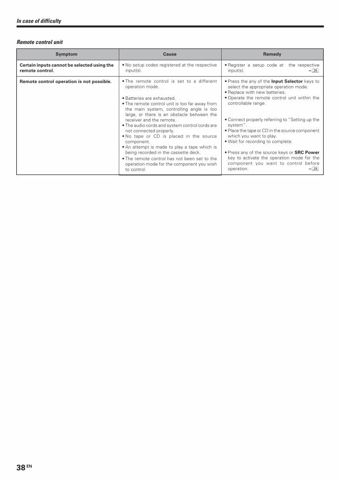
38 EN
In case of difficulty
Remote control unit
Cause
• No setup codes registered at the respectiveinput(s).
• The remote control is set to a differentoperation mode.
• Batteries are exhausted.• The remote control unit is too far away from
the main system, controlling angle is toolarge, or there is an obstacle between thereceiver and the remote.
• The audio cords and system control cords arenot connected properly.
• No tape or CD is placed in the sourcecomponent.
• An attempt is made to play a tape which isbeing recorded in the cassette deck.
• The remote control has not been set to theoperation mode for the component you wishto control.
Remedy
• Register a setup code at the respectiveinput(s). •
• Press the any of the Input Selector keys toselect the appropriate operation mode.
• Replace with new batteries.• Operate the remote control unit within the
controllable range.
• Connect properly referring to “Setting up thesystem”.
• Place the tape or CD in the source componentwhich you want to play.
• Wait for recording to complete.
• Press any of the source keys or SRC Power
key to activate the operation mode for thecomponent you want to control beforeoperation. ª
Symptom
Certain inputs cannot be selected using the
remote control.
Remote control operation is not possible.
*5330/37-40/EN 1/21/03, 9:58 PM38
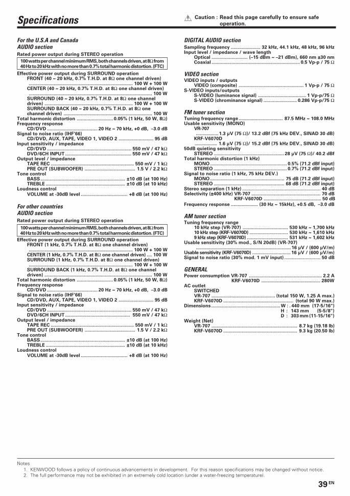
39 EN
Specifications Caution : Read this page carefully to ensure safe
operation.
For the U.S.A and CanadaAUDIO sectionRated power output during STEREO operation
Effective power output during SURROUND operationFRONT (40 ~ 20 kHz, 0.7% T.H.D. at 8Ω one channel driven)............................................................................... 100 W + 100 W
CENTER (40 ~ 20 kHz, 0.7% T.H.D. at 8Ω one channel driven).............................................................................................. 100 W
SURROUND (40 ~ 20 kHz, 0.7% T.H.D. at 8Ω one channeldriven) ................................................................... 100 W + 100 WSURROUND BACK (40 ~ 20 kHz, 0.7% T.H.D. at 8Ω onechannel driven) ................................................................... 100 W
Total harmonic distortion ........................... 0.05% (1 kHz, 50 W, 8Ω)Frequency response
CD/DVD ...................................... 20 Hz ~ 70 kHz, +0 dB, –3.0 dBSignal to noise ratio (IHF’66)
CD/DVD, AUX, TAPE, VIDEO 1, VIDEO 2 .......................... 95 dBInput sensitivity / impedance
CD/DVD ................................................................ 550 mV / 47 kΩDVD/6CH INPUT .................................................. 550 mV / 47 kΩ
Output level / impedanceTAPE REC ............................................................... 550 mV / 1 kΩPRE OUT (SUBWOOFER) ...................................... 1.5 V / 2.2 kΩ
Tone controlBASS................................................................ ±10 dB (at 100 Hz)TREBLE ............................................................ ±10 dB (at 10 kHz)
Loudness controlVOLUME at -30dB level ................................... +8 dB (at 100 Hz)
For other countriesAUDIO sectionRated power output during STEREO operation
Effective power output during SURROUND operationFRONT (1 kHz, 0.7% T.H.D. at 8Ω one channel driven)............................................................................... 100 W + 100 W
CENTER (1 kHz, 0.7% T.H.D. at 8Ω one channel driven) .... 100 WSURROUND (1 kHz, 0.7% T.H.D. at 8Ω one channel driven)............................................................................... 100 W + 100 W
SURROUND BACK (1 kHz, 0.7% T.H.D. at 8Ω one channeldriven) .................................................................................. 100 W
Total harmonic distortion ........................... 0.05% (1 kHz, 50 W, 8Ω)Frequency response
CD/DVD ...................................... 20 Hz ~ 70 kHz, +0 dB, –3.0 dBSignal to noise ratio (IHF’66)
CD/DVD, AUX, TAPE, VIDEO 1, VIDEO 2 .......................... 95 dBInput sensitivity / impedance
CD/DVD ................................................................ 550 mV / 47 kΩDVD/6CH INPUT ................................................. 550 mV / 47 kΩ
Output level / impedanceTAPE REC ............................................................... 550 mV / 1 kΩPRE OUT (SUBWOOFER) ...................................... 1.5 V / 2.2 kΩ
Tone controlBASS................................................................ ±10 dB (at 100 Hz)TREBLE ............................................................ ±10 dB (at 10 kHz)
Loudness controlVOLUME at -30dB level ................................... +8 dB (at 100 Hz)
DIGITAL AUDIO sectionSampling frequency ...................... 32 kHz, 44.1 kHz, 48 kHz, 96 kHzInput level / impedance / wave length
Optical ........................... (–15 dBm ~ –21 dBm), 660 nm ±30 nmCoaxial ................................................................... 0.5 Vp-p / 75 Ω
VIDEO sectionVIDEO inputs / outputs
VIDEO (composite) ................................................. 1 Vp-p / 75 ΩS-VIDEO inputs/outputs
S-VIDEO (luminance signal) .................................... 1 Vp-p/75 ΩS-VIDEO (chrominance signal) ......................... 0.286 Vp-p/75 Ω
FM tuner sectionTuning frequency range ................................. 87.5 MHz ~ 108.0 MHzUsable sensitivity (MONO)
VR-707.................1.3 µV (75 Ω)/ 13.2 dBf (75 kHz DEV., SINAD 30 dB)
KRF-V6070D................... 1.6 µV (75 Ω)/ 15.2 dBf (75 kHz DEV., SINAD 30 dB)
50dB quieting sensitivitySTEREO ..................................................... 28 µV (75 Ω)/ 40.2 dBf
Total harmonic distortion (1 kHz)MONO.......................................................... 0.5% (71.2 dBf input)STEREO ....................................................... 0.7% (71.2 dBf input)
Signal to noise ratio (1 kHz, 75 kHz DEV.)MONO........................................................ 75 dB (71.2 dBf input)STEREO ..................................................... 68 dB (71.2 dBf input)
Stereo separation (1 kHz) ........................................................... 40 dBSelectivity (±400 kHz) VR-707 .................................................... 70 dB KRF-V6070D ........................................... 50 dB
Frequency response .................... (30 Hz ~ 15kHz), +0.5 dB, –3.0 dB
AM tuner sectionTuning frequency range
10 kHz step (VR-707) .................................. 530 kHz ~ 1,700 kHz10 kHz step (KRF-V6070D) ............................. 530 kHz ~ 1,610 kHz9 kHz step (KRF-V6070D) ............................... 531 kHz ~ 1,602 kHz
Usable sensitivity (30% mod., S/N 20dB) (VR-707)........................................................................ 16 µV / (600 µV/m)
Usable sensitivity (KRF-V6070D) ............................. 16 µV / (600 µV/m)Signal to noise ratio (30% mod. 1 mV input) ........................... 50 dB
GENERALPower consumption VR-707 ....................................................... 2.2 A
KRF-V6070D ............................................. 280WAC outlet
SWITCHEDVR-707 ................................................ (total 150 W, 1.25 A max.)KRF-V6070D ..................................................... (total 90 W max.)
Dimensions ....................................................W : . 440 mm (17-5/16")H : 143 mm (5-5/8")D : 303 mm (11-15/16")
Weight (Net)VR-707 ................................................................. 8.7 kg (19.18 lb)KRF-V6070D ........................................................ 9.3 kg (20.50 lb)
Notes1. KENWOOD follows a policy of continuous advancements in development. For this reason specifications may be changed without notice.2. The full performance may not be exhibited in an extremely cold location (under a water-freezing temperature).
100 watts per channel minimum RMS, both channels driven, at 8Ω from40 Hz to 20 kHz with no more than 0.7% total harmonic distortion. (FTC)
100 watts per channel minimum RMS, both channels driven, at 8Ω from40 Hz to 20 kHz with no more than 0.7% total harmonic distortion. (FTC)
*5330/37-40/EN 1/23/03, 2:02 PM39

For your recordsRecord the serial number, found on the back of the unit, in the spacesdesignated on the warranty card, and in the space provided below. Referto the model and serial numbers whenever you call upon your dealer forinformation or service on this product.
Model_____________________ Serial Number_____________________
*5330/37-40/EN 1/21/03, 9:58 PM40