keor tups.legrand.com/media/document/le07543ac.pdf4 description of the symbols used in the manual...
TRANSCRIPT
KEOR T Operating Manual
LE07543AC

Keor T
ENGLISH 5-6EN


3
Keor T
Ope
ratin
g M
anua
l
Important Notices!Thank you for choosing LEGRAND UPS System to supply your Critical Application.
This manual contains important information about commissioning, usage and technical properties of the UPS. It also contains safety information for operator and instructions to secure your critical load. Applying the recommendation detailed in this manual is necessary to use UPS safely and correctly.
Read the manual completely before working on this equipment!
Keep this manual in UPS’s front cover’s pocket for easy consultation!
Reproduction, adaptation, or translation of this manual is prohibited without prior written permission of LEGRAND Company, except as allowed under the copyright laws.
The manufacturer reserves the rights to change the technical specifications and design without notice.
LEGRAND reserves the rights to change the information in this document without notice. Refer to http://ups.legrand.com/ web site to dowload last release and translations.
Units that are labelled with a CE mark comply with the Standard: EN 62040-1 and EN 62040-2.

4
Description of the Symbols Used in the Manual
This symbol points out the instructions which are especially important.
This symbol points out the risk of electric shock if the following instruction is not followed.
This symbol points out the instructions, which may result with injury of the operator or damage of the equipment if not followed.
All packing material must be recycled in compliance with the laws in force in the country where the system is installed.
Description of the Abbreviations Used in the GuideUPS: Uninterruptible Power SupplyESD: Emergency Switching DeviceRS232: Serial Communication ProtocolRS485: Serial Communication ProtocolMODBUS: Modicon Communication ProtocolSNMP: Simple Network Management ProtocolV: VoltA: AmpereP: Power
For Mains Supply, Auxiliary Mains Supply, Output, Battery Circuit Breaker and Maintenance Bypass Circuit Breaker;
“ON”: Closing the Circuit“OFF”: Opening the Circuit

5
Keor T
Ope
ratin
g M
anua
l
1. FOREWORD 7
1.1. Overview 7 1.2. Manual 7
2. WARRANTY 9
2.1. Terms of Warranty 9 2.2. Out of Warranty Terms and Conditions 9
3. SAFETY 10
3.1. Important Notice for UPS 10 3.2. Important Notice for Battery 10 3.3. Description of the Symbols Used on the Labels Applied to the UPS 10
4. OPERATION MODES 11
4.1. Online Mode 12 4.2. Battery Mode 12 4.3. Bypass Mode 13 4.4. Eco Mode 14 4.7. Operation with External Maintenance Bypass (Optional) 14
5. HUMAN MACHINE INTERFACE 15
5.1. Front Panel Segments 15 5.1.1.Colour Graphical Touchscreen 16 5.1.2.UPS Status LED Bar 18 5.2. Menu 19 5.2.1. Alarms Menu 19 5.2.2. Measurements Menu 20 5.2.3.Settings Menu 21 5.2.4.Diagnostics Menu 24 5.2.5. About Menu 26 5.2.6. Command Menu 26
6. COMMUNICATION 28
6.1. Serial Communication (RS232) 30 6.2. Internal SNMP Communication 30 6.3. Emergency Switching Device and Generator Connections 32 6.4. Dry Contacts 33 6.5. RS485 34
7. OPERATING PROCEDURES FOR SINGLE SYSTEMS 35
7.1. Preparations 35 7.2. Commissioning 36 7.2.1. Start-Up UPS with Internal Battery 36 7.2.2. Start-Up UPS with External Battery 36 7.3. Decommissioning 36
6
7.4. Maintenance Bypass Commissioning Instructions (Transfer Load Supply from UPS to Internal Maintenance Bypass) 37 7.5. Maintenance Bypass Decommissioning Instructions 37
8. OPERATING PROCEDURES FOR PARALLEL SYSTEMS 39
8.1. Introduction 39 8.1.1. Redundancy 39 8.1.2. Power Increase 39 8.2. Procedure for Commissioning and Start-Up 40 8.3. Procedure for Decommissioning 41
9. TROUBLESHOOTING 42
9.1. Bypass voltage failure Alarm 42 9.2. Bypass phase sequence wrong Alarm 42 9.3. Inverter not sync. with bypass Alarm 42 9.4. Input phase sequence wrong Alarm 42 9.5. Rectifier not sync. with input Alarm 42 9.6. DC voltage failure Alarms 42 9.7. ESD active Alarm 42 9.8. Ambient temperature high Alarm 42 9.9. Overload Alarms 43 9.10. Maintenance bypass active Alarm 43 9.11. Battery test failure Alarm 43 9.12. Input voltage failure Alarms 43 9.13. Inverter temperature high/ Rectifier temperature high Alarms 43
10. PREVENTIVE MAINTENANCE 44
10.1. Batteries 44 10.2. Battery Fuses 44 10.3. Fans 45 10.4. Capacitors 45
Appendix-1: Alarms List 46Appendix-2: Diagnostics List 47Appendix-3: Event List 48Appendix-4: Technical Specifications 50Appendix-6: Description of UPS and Block Diagram 52

7
Keor T
Ope
ratin
g M
anua
l
1. Foreword 1.1. Overview
Thank you for choosing LEGRAND UPS Keor -T product.
KEOR T has been designed with advanced technologies and the latest components generation; realized to satisfy both users and installers in their operational needs of high availability and performance.This UPS aims to be efficient, functional, safe and very easy to install and use. LEGRAND has studied the best way to reconcile high-tech performance and ease of use, making “user friendly” technologically advanced products.
KEOR T supplies maximum protection and power quality for any type of IT load, tertiary application, lighting or building.
Furthermore, standards deployed by Legrand for R&D, supplier selection and manufacturing complies with the highest quality standards. This product is manufactured in an ISO 9001 & ISO14001 certified factory in full compliance with the eco-design laws. The UPS Keor -T system is made in compliance with the existing European Community directives and with the technical standards in force to comply with CE marking as certified by the Declaration of Conformity issued by the Manufacturer.
Technology & Architecture
A special feature of Keor -T is Online Double Conversion Operation (VFI-SS-111 as defined by the reference standard EN 62040-3) based on the capacity to supply a voltage that is perfectly stabilized in frequency and amplitude, even in event of extreme alterations of mains power supply.The 3-Level Switching Technology used in this product is the latest solution to provide high energy efficiency even with low load conditions.
The energy efficiency performance of Keor -T surpasses the minimum requirements defined by the Code of Conduct on Energy efficiency and Quality of European of AC UPS defined by EC.
KEOR T represents the best solution combining high performance, low management costs and ease of operation and maintenance:• Dual Input • User friendly touch screen design• UPS via LED bar (with traffic light coding) gives an immediate diagnosis of the system under any conditions. • Internal Battery option as well as wide range external battery cabinets.• Isolation transformer can be mounted inside UPS cabinet upon request.• Integrated Maintenance Bypass• Parallelable to increase the power • Availability of different communication types
1.2. Manual
• The purpose of this manual is to provide indications for using the equipment safely and to carry out first level of troubleshooting. • This manual is addressed to persons already educated on precautions to adopt in face of electrical hazard• This manual is addressed to “User“, generic term to identify all persons that will have the need and / or obligation to provide instructions or operate directly this UPS equipment.• Adjustments, preventive and curative maintenance jobs are not dealt with in this manual as they are reserved exclusively to skilled and authorized Legrand UPS Technical Service Engineers. • The intended use and configurations envisaged for the equipment are the only ones allowed by the Manufacturer; do not attempt to use the equipment in disagreement with the indications given. Any other use or configuration must be agreed and written by the Manufacturer, in such a case, will be an enclosure to the manual.

8
• For its use the user must also comply with the specific laws in force that exist in the country where the equipment is installed. Reference is also made in this manual to laws, directives, etc., that the user must know and consult in order to fulfil the purposes established by the manual.• If information is exchanged with the Manufacturer or assistance personnel authorized by the former, please refer to the equipment’s rating plate data and serial number.• The manual must be kept for the equipment’s useful life cycle and, if necessary (e.g. damage which prevents it being consulted even partially) the user must ask the Manufacture for a new copy, quoting the publishing code on the cover.•The manual reflects the state of the art at the moment the equipment was put on the market, of which it is an integral part. The publication complies with the directives in force at such a date. The manual cannot be considered inadequate if updates of standards or changes are made to the equipment.• Any integration to the manual which the Manufacturer deems fitting to send to the users must be kept with the manual, becoming an integral part of it.• The Manufacturer is available to its clientele to provide additional information and will take into consideration any suggestions made to improve this manual to bring it even closer to the requirements for which it was drawn up.• If the equipment is sold, which always includes handing over this operating manual, the primary user must notify the Manufacturer, giving him the address of the new user so the latter can be reached if there are any communications and/or updates deemed indispensable.
Reproduction partilally or totally, adaptation, or translation of this manual is prohibited even via electronic means without prior written permission of LEGRAND Company, except as allowed under the copyright laws.
The manufacturer reserves the rights to change the technical specifications and design without notice.
LEGRAND reserves the rights to change the information in this document without notice. Refer to http://ups.legrand.com/ web site to dowload last release and translations.
This equipment is labelled with a CE mark and complies with the Standard: EN 62040-1 and EN 62040-2.
Read the manual completely before working on this equipment!
Keep this manual in UPS’s front cover’s pocket for easy consultation!
9
Keor T
Ope
ratin
g M
anua
l
2. Warranty 2.1. Terms of Warranty• Warranty is defined by General Conditions of Sale and Delivery.• The UPS including all the internal parts is under the warranty of LEGRAND. • If the UPS malfunctions because of component, manufacturing or installation (if it’s done by authorized LEGRAND UPS Technical Service Personnel) problems during the warranty period, the UPS will be repaired (spares and labour) by the Manufacturer under warranty.
2.2. Out of Warranty Terms and ConditionsThis Warranty does not apply if:• UPS not commissioned or maintained by an authorized LEGRAND UPS Technical Service staff or an authorized LEGRAND distributor Technical Service staff• UPS not used according the terms of operating and installation manual• Product serial number label has been removed or lostThis Warranty does not cover any defects or damages caused by:• Neglect, accident, misuse, misapplication • Failure due to fortuitous circumstances or force majeure (lightning, floods…etc.),• Unloading and transportation damage and failures after delivery,• Damage or injuries caused by negligence, lack of inspection or maintenance, or improper use of the products,• Faulty electrical wiring,• Defects arising either from designs or parts imposed or supplied by the purchaser, • Defects and damage by fire and lightning,• Failures due to modification in the products without LEGRAND approval,• Improper installation, testing, operation, maintenance, repair, alteration, adjustment, or modification of any kind by unauthorized personnel, The Manufacturer will repair the device in such cases for a fee and is not responsible for the shipment of the equipment. The Battery warranty does not apply if the temperature in the room exceeds 25 °C.Extended battery warranty does not apply if:
• UPS has not been commissioned • A yearly preventive maintenance visit has not been performed
By an authorized LEGRAND UPS Technical Service staff or authorized LEGRAND distributor Technical Service staff.
The UPS may contain batteries that should be recharged 24Hours min after 6 month storage duration to avoid deep battery discharge. Warranty cannot apply on batteries that have suffered of deep discharge.
10
• The equipment may only be installed and commissioned by authorized Legrand UPS Technical Service Personnel.
• This manual contains important instructions that you should follow during installation and maintenance of the UPS and batteries. Please read all instructions before operating the equipment and save this manual for future reference.
• Not obeying the instructions written on this manual which may result with possible injury of the operator or damage of the equipment.
• Even when connections removed, residual voltages of capacitors and/or high temperature may exist on connection terminals and inside the UPS. Before working on terminals, check between all the terminals included PE that no hazardous voltages exist.
• According to IEC 62040-2; this is a product for commercial and industrial application. In the second environment installation restrictions or additional measures may be needed to prevent disturbances.
• The equipment shall be packed and fixed properly during transportation to avoid fall down and proper equipment should be used for transportation. Never transport in horizontal position.
• The UPS must always stands in a vertical position. Make sure that the floor can support the weight of the system.
• UPS is designed for indoor use. To reduce the risk of fire or electric shock, install this UPS in a temperature and humidity controlled indoor environment, free of conductive contaminants. Ambient temperature must not exceed 40°C (104°F). Do not operate near water or excessive humidity (95% maximum without condensation).
• Contact your local recycling or hazardous waste center for information on proper disposal of the used battery or UPS.
• In case of an extraordinary situation (damaged body, cabinet or connections, penetration of foreign materials into the body or cabinet etc.) deenergize the UPS immediately and consult to the LEGRAND Technical Assistance Center.
3.2. Important Notice for Battery• The batteries may only be installed and commissioned by authorized Legrand UPS Technical Service Personnel.• Do not dispose of batteries in a fire. The batteries may explode.
• Do not open or mutilate batteries. Released electrolyte is harmful to the skin and eyes. It may be toxic.
• In case of electrolyte in contact with skin, immediately wash the contamimated skin with water.
• A battery can present risk of electric shock and high short circuit currents.
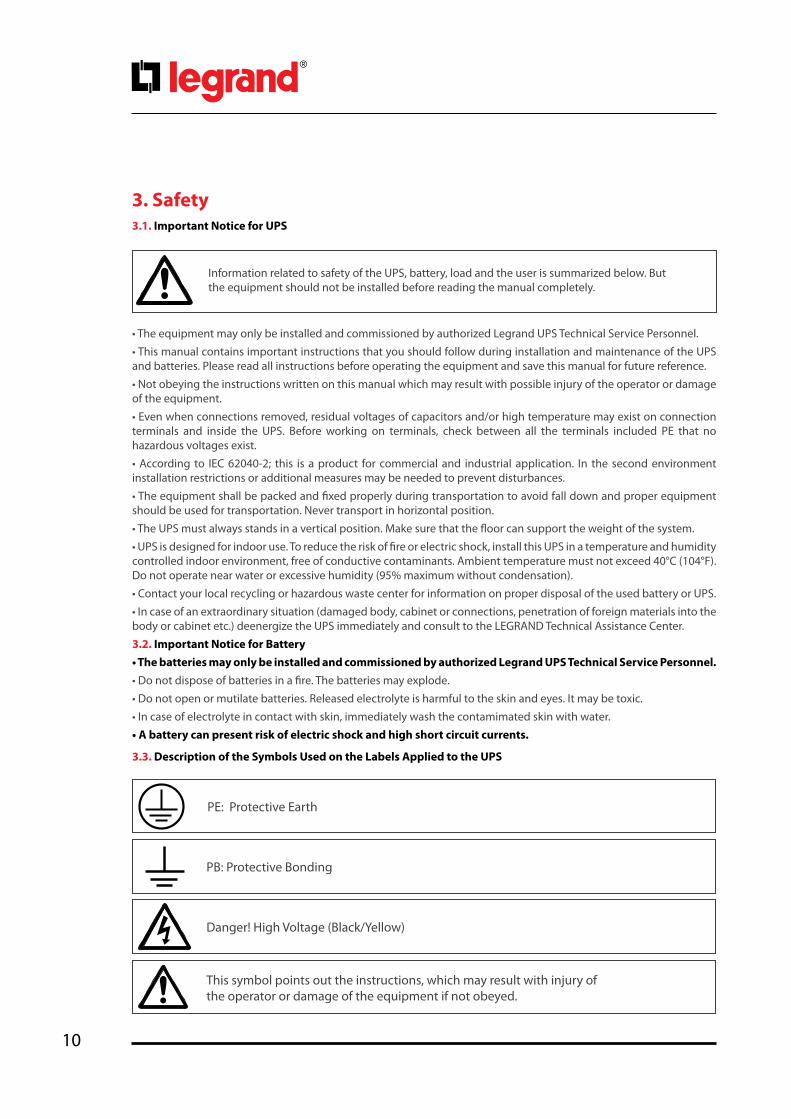
3.3. Description of the Symbols Used on the Labels Applied to the UPS
3.1. Important Notice for UPS
3. Safety
Information related to safety of the UPS, battery, load and the user is summarized below. But the equipment should not be installed before reading the manual completely.
PE: Protective Earth
PB: Protective Bonding
Danger! High Voltage (Black/Yellow)
This symbol points out the instructions, which may result with injury of the operator or damage of the equipment if not obeyed.

11
Keor T
Ope
ratin
g M
anua
l
4. Operation ModesUninterruptible Power Supplies (UPS) most important function is the protection of critical and sensitive loads from the irregular mains voltage conditions. They are used to supply uninterruptible energy to these loads in such irregular mains voltage conditions and provide regulated energy supply to the equipment present in the IT room, industrial workshop, hospitals and offices.
Keor T UPS during Inverter operation provides stable pure sine wave. This pure sine wave is not affected from the input voltage fluctuations. This helps to extend the life time of your sensible loads. Power factor of the current consumed from the mains voltage is nearly one. You do not have any problem on generator or isolation transformer applications. The reactive energy consumption decreases.
During the mains voltage failure, the energy needed for the load is provided by the internal battery (or installed in external battery cabinet/s). These batteries are charged by an intelligent battery charging circuit during the mains voltage within the limits. Batteries are lead acid battery (VRLA) and do not require any maintenance until the end of their life time.
In case of longer overload or inverter failure situation, UPS transfers the load to bypass line, and load is supplied from the mains voltage. When the condition turns back to normal, UPS will continue to supply the load through inverter.
UPS control and management is done by Digital Signal Processor (DSP) which is 200 times faster than standard microprocessors. This helps to make your UPS smarter. DSP uses all the sources on optimum conditions, observes the failure conditions, and communicates with your computer system.
UPS can be operated in one of the following operational modes depending on the condition of common/auxiliary mains voltage, battery, bypass, UPS and/or user preference.
You may see the block diagram of UPS in Appendix-6 Description of UPS and Block Diagram.

12
4.1. Online Mode
Energy is drawn from the mains voltage input. Loads are supplied through the rectifier and the inverter. The AC voltage at the input is converted to a DC voltage by the rectifier. The inverter converts this DC voltage to an AC voltage with a stable sinusoidal waveform, amplitude and frequency. Output voltage and frequency can be set via front panel. Output voltage is sinusoidal and has a regulated amplitude and frequency. It is independent from the input voltage. The loads are not affected by the disturbances of the mains voltage.
If the mains voltage and frequency are in an acceptable range, Online Operation is possible. Check Appendix-4 Technical Specifications for Online Operation mode mains voltage limits.
The upper limit of mains voltage is independent from the load percentage and it is Ph-N: 270V. UPS switch-es to Battery Operation mode when the mains voltage is over Ph-N: 270V. The mains voltage is required to decrease below Ph-N: 260V for UPS to return Online Operation.
Online Operation Conditions;
In case Online Operation is set as operation mode of UPS, the mains voltage is within the limits and/or if there is no abnormal condition (overheat, overload, failure…etc.) UPS operates in Online Operation. Except for failures, as soon as the abnormal conditions are eliminated, UPS switches to Online Operation automati-cally.
In case Bypass Operation is set as operation mode of UPS and the voltage and frequency is out of the by-pass limits but within the rectifier limits, UPS swithes to Online Operation.
4.2. Battery Mode
In this operation, energy is drawn from the batteries. The loads are supplied via inverter. Output voltage is sinusoidal and has a regulated amplitude and frequency.
Battery voltage should be in acceptable limits and the inverter should be enabled for the UPS to operate in this mode.
UPS operates in Battery Operation in the following cases:
• While UPS is operationg in Online Operation; if frequency/waveform/rms value of mains voltage go be-yond the rectifier limits,
• While UPS is operationg in Bypass Operation, if frequency/waveform/rms value of mains voltage go be-yond Bypass limits,
• If Inverter enabled: “YES”, Rectifier enabled: “NO” are selected through the front panel (Authorisations Menu for authorized Service Staff).
Keor T UPS operates with one or several parallel strings of 1 x 60pcs 12VDC battery with common neutral.You may see the battery string connection as below;
+ -
n x 30 pcs n x 30 pcs
POSITIVE STRING
NEUTRAL POINT
N
NEGATIVE STRING
Two Serial Strings with Central Point – Neutral Potential –

13
Keor T
Ope
ratin
g M
anua
l
Battery Management and Battery Back-Up Time
When UPS operates in Online or Bypass Operation; it continuously calculates and displays the remaining back-up time. However the calculated values will be healthier and accurate a few minutes after the UPS switches to Battery Operation.
Autonomy time depends on battery type, quantity, capacity, situation and load level. UPS stops supplying the loads if the battery voltage decreases under a specific value.
Battery life depends on some parameters such as battery type, charge-discharge cycle, and depth of dis-charge, ambient temperature, conditions. Please check Technical Specifications for the ideal environmental conditions for the batteries. Using the batteries outside this temperature range will decrease battery opera-tion time and battery life.
4.3. Bypass Mode
UPS transfers the loads automatically to the mains voltage in order to protect them during abnormal condi-tions.
While UPS operates in Online Operation, UPS switches to bypass automatically (in case the mains voltage and frequency is within the limits of bypass) in the following conditions;
• During start-up
• Bypass Priority
• Inverter Fault
• Prolonged Overload, output short circuit
• High Heatsink Temperature
After these conditions are eliminated, the UPS automatically returns to inverter.
Bypass Operation Voltage Range
The mains voltage is required to be in certain range for Bypass Operation. Voltage tolerance is set 18% of the output voltage in the factory. For instance; if the output voltage is Ph-Ph: 400V, the tolerance range of bypass voltage would be Ph-Ph: 328V – 472V. In case the input voltage decreases below Ph-Ph: 328V or in-creases above Ph-Ph: 472V; if UPS runs in Bypass Mode UPS switches to Online Mode Operation; if UPS runs in Online Mode Operation it cannot switch to Bypass Mode Operation even if a fault occurs. If the batteries and the inverter are suitable to supply the loads, UPS switches to Battery Mode Operation.
Bypass Mode Operation voltage tolerance limit can be adjusted in certain ranges depends on the cus-tomer’s request on site by Legrand UPS Technical Service Personnel.
To return to Bypass Mode Operation; the mains voltage should turn back to +5V above of lower limit, -5V down of upper limit of bypass limits. Default settings are Ph-Ph: 333V – 465V for Ph-Ph: 400V UPS.
Prolonged overloads in Bypass Operation may cause the thermal/magnetic protection act. In this case, all loads will be deenergized.
14
4.4. Eco Mode
Eco Mode Operation can be chosen through the Commands Menu. The purpose of using this mode is to increase the efficiency up to 98% and to provide energy saving; since the loads are supplied by the mains voltage directly, the loads are unprotected against any possible future risks. (e.g. surge voltage, etc.). In devices with auxilary mains supply; energy is drawn from the auxilary mains supply.
As long as the mains voltage and frequency within the limits, the load is supplied by the auxiliary voltage in a controlled manner; double conversion chain is on standby while ensuring the recharge of the batteries.
Eco Mode Operation does not provide perfect stability in frequency/waveform/rms value of the output voltage as in Online Operation. Thus, the use of this mode should be carefully executed according to the level of protection required by the application.
This procedure may only be executed by trained Personnel.
During Maintenance Bypass operation; in case of any mains voltage interruption occurs, all loads on the output will be deenergized. Maintenance Bypass Operation should not be preferred for long time use.
4.7. Operation with External Maintenance Bypass (Optional)The external manual maintenance bypass may be installed in the general distribution panel where Keor T is installed, or in an external bypass panel that is supplied on request.This operating mode enables the user to isolate the electronic circuitry of the UPS from the mains voltage and the load without interrupting the load operation by connecting the loads directly to the bypass utility supply. This feature is useful while performing maintenance or service and should only be executed by trained Personnel.
Maintenance Bypass enables the user to isolate the electronic circuitry of the UPS from the mains voltage and the load without interrupting the load operation by connecting the loads directly to the bypass utility supply. This feature is useful while waiting service staff and should only be executed by trained Personnel.
UPS switches to another mode in case the mains voltage or frequency goes beyond the Bypass limits. UPS returns to Eco Mode Operation when the auxiliary voltage returns to the limits.
Eco Mode Operation does not provide electronic short circuit current limitation. If a short circuit occurs downstream distribution panel supplied by the UPS, the magnetic protection off the Bypass line MCCB may act if not selective with downstream protection and all loads will be de energized. Check discrimination applies between upstream and downstream switchboard.
4.5. No Operation
This mode is used to make settings through Front Panel or by Service Software. To start-up UPS in No Operation mode; all the circuit breakers must be at “0” position except Q1 Input circuit breaker and Q4 Bypass circuit breaker. In this mode UPS does not apply output voltage to supply the loads. After all settings done during No Operation Mode, UPS should be resarted for the new service settings to be saved and valid. It is not necessary to restart UPS for user settings to be valid.
4.6. Operation with Maintenance Bypass
15
Keor T
Ope
ratin
g M
anua
l
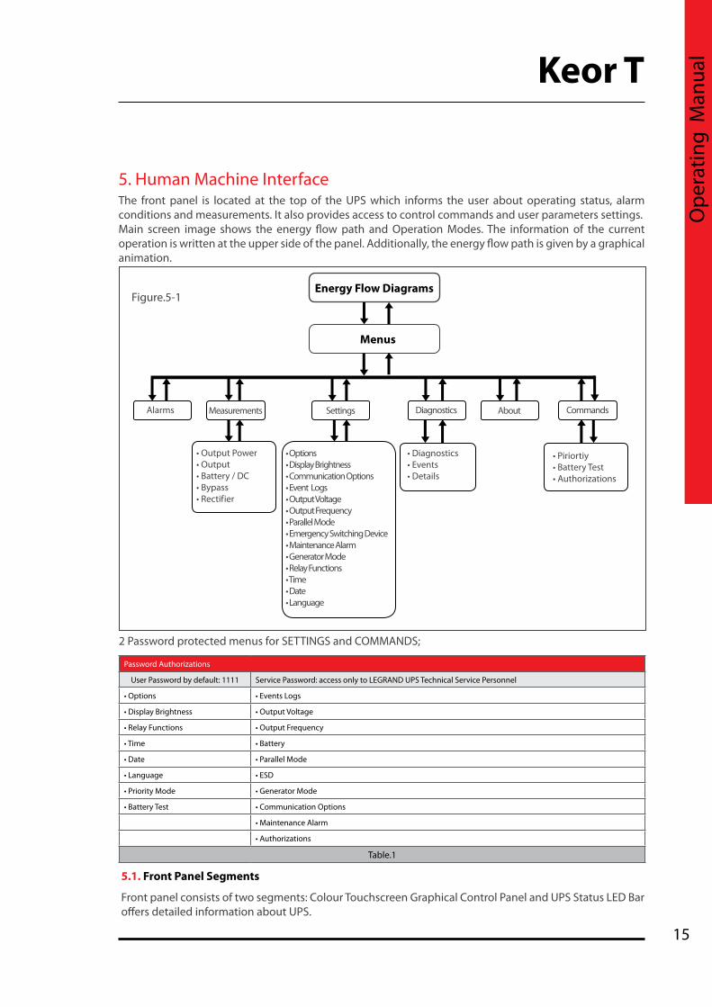
2 Password protected menus for SETTINGS and COMMANDS;
Figure.5-1
5.1. Front Panel Segments
Front panel consists of two segments: Colour Touchscreen Graphical Control Panel and UPS Status LED Bar offers detailed information about UPS.
The front panel is located at the top of the UPS which informs the user about operating status, alarm conditions and measurements. It also provides access to control commands and user parameters settings. Main screen image shows the energy flow path and Operation Modes. The information of the current operation is written at the upper side of the panel. Additionally, the energy flow path is given by a graphical animation.
5. Human Machine Interface
Energy Flow Diagrams
Menus
Alarms Measurements Settings Diagnostics About Commands
• Output Power• Output• Battery / DC• Bypass• Rectifier
• Diagnostics• Events• Details
• Piriortiy• Battery Test• Authorizations
• Options• Display Brightness• Communication Options• Event Logs• Output Voltage• Output Frequency• Parallel Mode• Emergency Switching Device• Maintenance Alarm• Generator Mode• Relay Functions• Time• Date• Language
Password Authorizations
User Password by default: 1111 Service Password: access only to LEGRAND UPS Technical Service Personnel
• Options • Events Logs
• Display Brightness • Output Voltage
• Relay Functions • Output Frequency
• Time • Battery
• Date • Parallel Mode
• Language • ESD
• Priority Mode • Generator Mode
• Battery Test • Communication Options
• Maintenance Alarm
• Authorizations
Table.1

16
5.1.1. Colour Graphical Touchscreen
Energy Flow Diagram/Modes Of Operation and Menus are displayed on LCD.
The description of the symbols in the energy flow diagram:Bypass Input: If Bypass voltage is OK and synchronizes with inverter; it lits Green, If Bypass voltage is OK and not synchronizes with inverter; it lits Orange.Rectifier Input: If Input voltage is OK, it lits Green.Rectifier: Converts AC voltage at the input into DC voltage. You may reach the rectifier measurements by touching it. Bypass Line: Shows that the loads are supplied via Bypass and line colour is Orange. If UPS is on Eco Mode it is Green. Battery: Shows battery conditions. If it is discharging the indicator goes down, if it is charging the indicator goes up. You may reach the battery/DC measurements by touching it. Inverter: Converts DC voltage into AC voltage. You may reach the output measurements by touching it. Operation Mode Information: Shows UPS’s current operation mode. Load: Shows the percentage of the load as numerical and graphical information. If there is overload at the output the load graphic lits Red. You may reach the output power measurements by touching it.Menu: You may reach the menus by touching it.Configuration: It indicates if UPS is in parallel or single operation configuration. In Single Mode; there is no symbolTime: It indicates the time.Circuit Breaker: It appears if battery Fuse is in “OFF” position or battery fuse has blown. If battery Fuse is in “ON” position; the circuit breaker icon is not displayed, instead battery capacity percentage is displayed. Alarms: If there is an alarm on UPS this icon appears and informs the user by flashing. You may reach the alarms by touching it.Exclamation Mark: Indicates that there is a problem where the icon appears.Transfer: Indicates that transfer to bypass is disabled. Wrench: Indicates that UPS requires Periodic Preventive Maintenance. Temperature: Indicates ambient temperature of UPS is too high. Generator Mode: Indicates UPS operates on Generator Mode.
10
1
2 3
14 5
6
12
1413
18
416
15
8
11
17
7 9
1
2
3
4
5
6
78
910
11
12
13
1415161718

17
Keor T
Ope
ratin
g M
anua
l
Operation Modes of UPS and Energy Flow Diagram;
Online Mode:
Frequency Converter Mode:
Battery Mode:
Bypass Mode:
*Bypass Line is Orange

18
Eco Mode:
*Bypass Line is Green
Maintenance Bypass Mode:
*Bypass Line is Orange and no battery charging
5.1.2. UPS Status LED Bar
Status LED Bar under the front panel gives information of current UPS status.
No Operation:
You may see the colour code assigned for status of UPS;• GREEN: Everything is OK on UPS. Load is protected.• ORANGE: The load is supplied by UPS but an alarm is active, control is required.• RED: The load is not supplied by UPS. Emergency exists.

19
Keor T
Ope
ratin
g M
anua
l
5.2. Menu
The related sub-menus under the main Menu can be reached by touching MENU icon while main screen image is displayed. They provide information to user about the measurements, about the UPS and status of UPS.
By touching Back icon you may exit from the menu.
You may see the sub-menus as shown below;
5.2.1. Alarms Menu
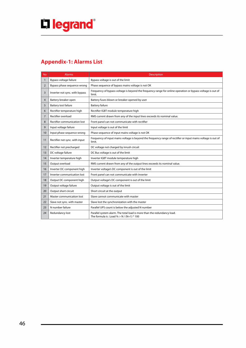
UPS displays 24 different alarms in Alarms menu. For detailed information about alarms please check Appendix-1-Alarms List.
You may reach sub-menus by touching Menu; Alarms, Measurements, Settings, Diagnostics, About and Commands.
All active alarms present are displayed on the Alarms screen.
They will appear in red colour and as soon as acknowledged by touching the hand icon at the right side of the screen, they switch to gray colour and the buzzer will stop.
In case a new alarm occurs; the buzzer is activated, new alarmit is displayed in red in addition with the remaining active alarms already acknowledged. It is necessary to acknowledge again the new alarm to stop the buzzer, then alarm text switch to gray colour

20
5.2.2. Measurements Menu
It provides useful measurements about the UPS and the load.
You may scroll to right and left by touching right and left keys through Measurements menu. The screens of MEASUREMENTS menu are as below:
Output load percentage, apparent power, real power and power factor information of each phase is displayed.
Output voltage (Ph-N), current, frequency information of each phase is displayed.
DC Bus and Positive-Negative string of battery voltage is displayed.
When the battery circuit breaker is closed, it gives just Battery Voltage measurements.
Charge (+) / Discharge (-) battery current, ambient temperature and back-up time are displayed.

21
Keor T
Ope
ratin
g M
anua
l
Bypass voltage (Ph-N) and frequency information of each phase are displayed. If the MAINS and AUX Supply are connected in COMMON, Rectifier and Bypass values will be the same.
Rectifier voltage (Ph-N), current and frequency information of each phase are displayed. If the MAINS and AUX Supply are connected in COMMON, Rectifier and Bypass values will be the same.
When the Password Screen appears, enter 1111, touch ENTER to confirm.
5.2.3. Settings Menu
This menu is the section where all the settings related to UPS usage customization can be done.
User Password must be entered to make changes in this section.
User Password: 1111 (the password cannot be changed)

22
UPS gives audible warning when alarm occurs. Alarm voice can be disabled if requested.
UPS gives audible echo when keyboard is used. Key voice can be disabled if requested.
You can adjust brightness setting of LCD screen.
When you touch the save icon key, a confirmation pop-up bar will appear.
You should touch Yes to save the settings. Touch No to exit without saving the changes.
You may choose communication options here.
If Modbus is chosen; you may also make Modbus adjustments.
There are 4 different relays and one alarm is assigned to each relay.

23
Keor T
Ope
ratin
g M
anua
l
There are 7 different alarms defined.
By default one alarm is assigned to each relay; however this can be changed by the user. It is also possible to assign the same alarm to each of the 4 relays. You may set each relay via this menu.
When you touch the save icon key, a confirmation pop-up bar will appear.
You should touch Yes to save the settings. Touch No to exit without saving the changes.
UPS records the event logs with the date and time information. Thus, the events can be followed chronologically.
When you touch the save icon key, a confirmation pop-up bar will appear. You should touch Yes to save the settings. Touch No to exit without saving the changes.
UPS records the event logs with the date and time information. Thus, the events can be followed chronologically.
When you touch the save icon key, a confirmation pop-up bar will appear. You should touch Yes to save the settings. Touch No to exit without saving the changes.
Set the date and time of UPS during pre-setting.

24
You may choose the language package installed in UPS.
When you touch the save icon key, a confirmation pop-up bar will appear. You should touch Yes to save the settings. Touch No to exit without saving the changes.
When you touch the save icon key, a confirmation pop-up bar will appear.
You should touch Yes to save the settings. Touch No to exit without saving the changes.
You may see UPS status here. There are 17 different notifications.
When you touch the calendar icon; you may reach below Event Menu.
5.2.4. Diagnostics Menu
All the alarms/notifications are logged real-time and can be reached via this menu.
UPS displays up to 380 last events. Events are stored in EEPROM using FIFO method. Order number of last occurred event is 001, the oldest event is erased.
You may touch right/left arrow through the menu pages. When you touch any event log, you may reach the details of it.

25
Keor T
Ope
ratin
g M
anua
l
You may see the logged events with time and date stamp.
Events are stored in EEPROM using FIFO method.
When you touch any event log, you may reach the details of it as you see on the side.
You may see the details of the event with event code.
If Technical Support required; taking notes of current event logs would be useful.
You may reach detailed information about events from Appendix-3: Event List.
03.01.2012 21:23
Back
Event descripton
Flags
Rectifier reception timeout
0x2940 0x15F0 0xe628 0x0322
Details [ Online ]

26
5.2.5. About Menu
This menu provides information about the UPS itself.
5.2.6. Command Menu
Through this menu; you may send some commands to UPS. User Password must be entered to make changes in this section.
User Password: 1111 (the password cannot be changed).
You may see the COMMAND Menu’s screen as below;
• UPS: UPS model and nominal power
• Serial: UPS serial number
• UPS output: UPS output voltage (Ph-N / Ph-Ph) and frequency
• HMI version: Human Machine Interface version
• Inverter version: Inverter firmware version
• Rectifier version: Rectifier firmware version
When the Password Screen appears, enter 1111, touch enter to confirm.

27
Keor T
Ope
ratin
g M
anua
l
Via this menu; you may choose operation mode of UPS as Online or Eco Mode.
If system is configured as Single; you may choose operation mode of UPS Online or Eco Mode.
When you touch the Save icon key, a confirmation pop-up bar will appear.
You should touch Yes to save the settings. Touch No to exit without saving the changes.
Via this menu; you may choose operation mode of UPS as Online or Bypass Mode.If system is configured as Parallel; you may choose operation mode of UPS Online or Bypass Mode. It would be enough to set the priority on one of the UPS, all the UPSs will pass to Bypass Mode at the same time. When you touch the Save icon key, a confirmation pop-up bar will appear. You should touch Yes to save the settings. Touch No to exit without saving the changes.
With this command, UPS battery test feature can be started. When you touch the Start test key, a confirmation pop-up bar will appear.
You should touch Yes to start the test; otherwise touch No. UPS tests the battery automatically once each 90 days.

28
6. CommunicationInterface connectivity cards allow UPS to communicate in a variety of networking environments and with different type of devices.
Standard and optional communication interfaces are listed below;
Communication Interfaces
Model (kVA) 10 15 20 30 40 60 80 100 120
RS232
RS485 / MODBUS
Dry Contacts
Generator Interface
Remote Emergency Switching Device (ESD) Interface
Internal SNMP / Web Monitoring / e-mail
External SNMP
Standard Option
Table.2
Inverter and Rectifier communication connectors are used for Technical Service only.Do no not connect RS232 or external SNMP, damage may occur to your equipment and cancel your warranty.
1 RS485 / Modbus
2 RS232 / External SNMP
3 Remote Emergency Switching Device interface
4 Generator Interface
5 Dry Contacts Interface
Internal SNMP Slot
Figure. 6 -1
1 2 3 4 5
29
Keor T
Ope
ratin
g M
anua
l
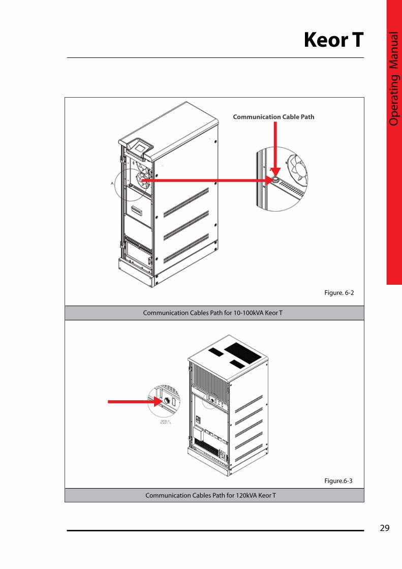
Communication Cable Path
Figure. 6-2
Figure.6-3
Communication Cables Path for 10-100kVA Keor T
Communication Cables Path for 120kVA Keor T

30
The communication solutions listed below can be used with this port:• Monitoring Software (Optional) • External SNMP Adapter (Optional)
Via SNMP; the information listed below can be monitored;
• The Latest Battery Test Date • UPS Information (example: 220V - 50Hz)• Input Data (Vin, Fin, Vmax etc.)• Output Data (Vout, Load Percantge...etc.)• Battery Situation (Vbatt...etc)
6.1. Serial Communication (RS232)UPS is equipped with Serial Communication as standard. RS232 cable shall be shielded and shorter than 25m.RS232: DSUB-9 male connector with the following pin layout shall be used on the UPS side of the connection cable.
RS232 Pin Layout
PIN# Signal Name Signal Description
2 RX Receive Data
3 TX Transmit Data
5 GND Signal Ground
Table.3
Over SNMP communication, battery test can be started or current test can be cancelled. UPS can be shut-down or stand-by (stand-by duration is adjustable). Alarms can be discarded.
6.2. Internal SNMP CommunicationInternal SNMP card can be installed into SNMP slot placed at the front of UPS. As soon as SNMP installed, RS232 port would be disabled.
Internal SNMP has the same features as External SNMP; refer to Section 6.1 for more information.
If Serial Communication cable is needed, it can be produced according to the pin configuration described at side.

31
Keor T
Ope
ratin
g M
anua
l
If the jumpers are at the upper side for internal SNMP configuration, RS232 and RS485 Serial Communication are disabled. If the jumpers are at the lower side for RS232 or RS485 configuration, internal SNMP is disabled.
SNMP JUMPER (J2 – J3): If internal SNMP would be used, 2 jumpers should be moved to upper side. If RS232 or RS485 would be used, 2 jumpers should be moved to lower side.
SNMP
SNMP RS232 - RS485
SNMP
RS232RS485
RS232RS485
J2 J2J3 J3

32
UPS output can be switched off immediately by Remote Emergency Switching Device interface (ESD) connection if desired. A remote latched switch can be used as described in above figure.
Pay attention to the polarity of the voltages applied to the digital input terminals.
Input Function
UPS OFF
If the UPS OFF input is set high by applying 5VDC voltage on the related terminals, UPS stops generating the output voltage and stops feeding the load. When the voltage on the digital input is removed, you have to restart UPS. The factory default setting of ESD contact is “Normally open”.
GEN ON
If the GEN ON input is set high by applying 5VDC voltage on the related terminals, UPS transfers to Generator Mode, bypass and battery charging is disabled. Generator icon appears on Energy Flow Diagram screen. The factory default setting of Generator contact is “Normally open”.
Table.4
6.3. Emergency Switching Device and Generator ConnectionsVoltage to be applied to the digital inputs is 5VDC. Maximum current drawn by each input is 1mA. 5VDC supply provided on the communication interface board can be used to supply both digital inputs.
Figure.6.3-1
Generator StartInformation

33
Keor T
Ope
ratin
g M
anua
l
6.4. Dry Contacts
There are 4 dry contact sockets on the Interface Board. The relays can be programmable from Relay Functions menu (under Settings menu). “General alarm, Input failure, Battery failure, Output failure, Bypass active, Output overload, High temperature” alarms can be assigned to the contacts. Each alarm can be assigned to separate relays but also one alarm may be assigned to all relays.
Each output socket 3-pin and middle pin is fixed, the upper pin is normally closed and lower pin is normally open.
You may see the relay numbers as above.
Maximum voltage to be applied to the relay contacts is 42VAC rms (sinus) or 60VDC. Maximum contact current depends on the applied voltage and the load characteristic. Both maximum voltage and maximum contact current corresponding to the applied voltage shall not be exceeded.
Free contact relay connection cables shall have a cross-section of 1.5 mm2.
Maximum allowed resistive contact currents for several voltages are given on the table below:
Each relay has both a normally open (NO) and a normally closed (NC) contact. One end of these contacts is common.
Relay functions are described below:
Relay functions can be changed through front panel.
Applied voltage Maximum contact current for resistive load
Up to 42 VAC 16 A
Up to 20 VDC 16 A
30 VDC 6 A
40 VDC 2 A
50 VDC 1 A
60 VDC 0.8 A
Table.5
Relay Default Function
Relay 1 General Alarm
Relay 2 Input failure
Relay 3 Battery failure
Relay 4 Output failure
Table.6

34
MODBUS END JUMPER (J4): If the UPS is at the end of the bus; the jumper should be moved to right side to close the bus.
The RS485 differential line consists of three pins:
• A is inverting pin (TxD-/RxD-)• B is non-inverting pin (TxD+/RxD+)• Middle Pin is reference pin (optional GND)
Middle Pin is the reference potential used by the transceiver to measure the A and B voltages.
The B line is positive (compared to A) when the line is idle.
6.5. RS485 RS485 with Modbus protocol is used in a wide range of automation systems for Industrial Process monitoring or for Building Management Systems. This communication link allows monitoring UPS status and measurements with such systems.
RS485
RS48
5
AB
Communication Parameters
Baud Rate 2400
Data Bits 8
Stop Bits 1
Parity No Parity
Flow Control No Flow Control
Communication Type RTU
Table.7
R24
R24
J4 J4
C18
C18
R22
R22
U1_485• U1_485•
DEFAULT MODBUS END
35
Keor T
Ope
ratin
g M
anua
l
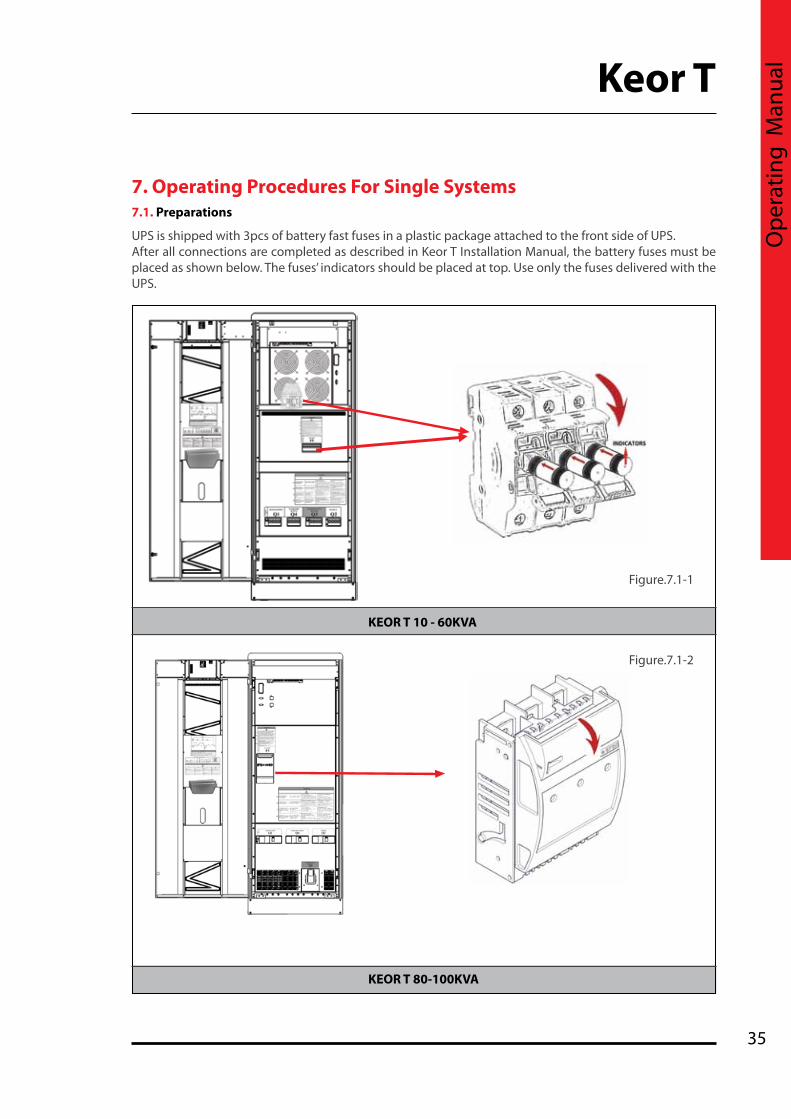
7. Operating Procedures For Single Systems7.1. Preparations
UPS is shipped with 3pcs of battery fast fuses in a plastic package attached to the front side of UPS. After all connections are completed as described in Keor T Installation Manual, the battery fuses must be placed as shown below. The fuses’ indicators should be placed at top. Use only the fuses delivered with the UPS.
Figure.7.1-1
KEOR T 10 - 60KVA
KEOR T 80-100KVA
Figure.7.1-2

36
Even without connections on UPS terminals, residual voltages may exist on these terminals and inside the UPS. Do not touch these parts.
* Keor T 120kVA battery fuses are fixed.
If you work on terminals; all circuit breakers in the input/bypass distribution panel, and all battery circuit breakers (F5 inside UPS and in the external battery cabinet, if any) should be brought to “OFF” position.
7.2.1. Start-Up UPS With Internal Battery1. Put the battery fast fuses into the battery circuit breaker on the UPS (F5). Do not close the circuit breaker yet!2. Switch the auxiliary supply circuit breaker on the distribution panel to “ON” position. 3. Switch the mains supply circuit breaker on the distribution panel to “ON” position. 4. Switch the auxiliary supply circuit breaker on the UPS (Q4) to “ON” position.5. Switch the mains supply circuit breaker on the UPS (Q1) to “ON” position. 6. Switch the inrush circuit breaker on the UPS (Q6) to “ON” position. 7.Touch Battery icon to see Battery / DC menu measurement. Do not close the battery circuit breakers (F5) until the difference between DC bus and Battery voltages decreases below 10V.8. Switch the output circuit breaker on the UPS (Q2) to “ON” position.9. Switch the output circuit breaker on the distribution panel to “ON” position.Afterwards UPS starts to supply the loads.
7.2.2. Start-Up UPS with External Battery
1. Put the battery fast fuses into the battery circuit breaker on the UPS (F5). Do not close the circuit breaker yet!2. Switch the auxiliary supply circuit breaker on the distribution panel to “ON” position. 3. Switch the mains supply circuit breaker on the distribution panel to “ON” position. 4. Switch the auxiliary supply circuit breaker on the UPS (Q4) to “ON” position. 5. Switch the mains supply circuit breaker on the UPS (Q1) to “ON” position. 6. Switch the inrush circuit breaker on the UPS (Q6) to “ON” position. 7. Switch the circuit breakers on the external battery cabinet to “ON” position.8. For the first start up after external battery cabinet installation, you need to check if no polarity inversion between battery cabinet and UPS. You can control voltages with multimeter on external battery connection terminals9. Touch Battery icon to see Battery / DC menu measurement. Do not close the battery circuit breakers (F5) until the difference between DC bus and Battery voltages decreases below 10V.10. Switch the output circuit breaker on the UPS (Q2) to “ON” position. 11. Switch the output circuit breaker on the distribution panel to “ON” position.Afterwards UPS starts to supply the loads.
7.2. Commissioning After all connections and settings have been done, UPS can be started-up.
Do not leave the battery fuse package at the front of UPS. Otherwise the fans would be blocked and UPS may overheat. Do not close battery fuse holder F5 before starting Commissioning procedure Section 7.2
Mount the battery fast fuses into battery fuse holder on the UPS. Fast fuses indicators side must be placed upper side of the holder.Do not close battery fuse holder F5 before reading Commissioning procedure Section 7.2

37
Keor T
Ope
ratin
g M
anua
l
7.3. DecommissioningFollow the order written below to decommission the UPS:1. Switch the output circuit breaker on the distribution panel to “OFF” position.2. Switch the output circuit breaker on the UPS (Q2) to “OFF” position. 3. Switch the battery circuit breaker on the UPS (F5) to “OFF” position.4. If exists, switch the circuit breakers on the external battery cabinet to “OFF” position.5. Switch the mains supply circuit breaker on the distribution panel to “OFF” position. 6. Switch the auxiliary supply circuit breaker on the distribution panel to “OFF” position. 7. Switch the inrush circuit breaker on the UPS (Q6) to “OFF” position. 8. Switch the mains supply circuit breaker on the UPS (Q1) to “OFF” position. 9. Switch the auxiliary circuit breaker on the UPS (Q4) to “OFF” position. Wait a few minutes till UPS completely turn off.
Even without connections on UPS terminals, residual voltages may exist on these terminals and inside the UPS. Do not touch these parts.
RISK OF BACKFEED: Before working on UPS terminals, check for Hazardous Voltage between all terminals including the protective earth (PE).
This procedure may only be executed by trained Personnel.
Some parts inside the UPS including terminals are still energized during maintenance bypass operation. All the maintenance operations should be done by authorized LEGRAND UPS Technical Service Personnel.
During Maintenance Bypass operation; in case any mains voltage interruption occurs, all loads supplied downstream the UPS will be de-energized. Maintenance Bypass Operation should not be preferred for long time use.
Maintenance bypass enables the user to isolate the electronic circuitry of the UPS from the mains voltage and the load without interrupting the load operation by connecting the loads directly to the bypass supply.This feature is useful while waiting service staff and shall only be executed by trained Personnel.In order to transfer to Maintenance Bypass without interruption, do the following instruction respectively; 1. On the display, select Menu / Command, enter User password (1111). 2. In page Priority, select Eco Mode, save and confirm, go back to Energy Flow Diagram screen3. Check that UPS is in Eco Mode operation.4. Open the front door with the UPS key. 5. Switch the maintenance bypass circuit breaker on the UPS (Q3) to “ON” position.6. See “M. Bypass Mode” written on LCD of UPS.7. Switch to “OFF” position the output circuit breaker (Q2), the battery circuit breakers (F5), the breakers on external battery cabinets if any, the mains supply circuit breaker (Q1) and the inrush circuit breakers (Q6) on the UPS. 8. Switch the auxiliary supply circuit breaker on the UPS (Q4) to “OFF” position. 9. LCD would be off and the alarms would be silenced. The loads will be continued to be supplied directly from the mains voltage.
7.4. Maintenance Bypass Commissioning Instructions (Transfer Load Supply from UPS to Internal Maintenance Bypass)
38
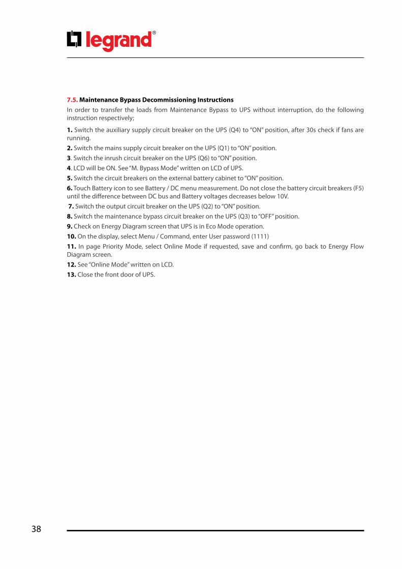
7.5. Maintenance Bypass Decommissioning InstructionsIn order to transfer the loads from Maintenance Bypass to UPS without interruption, do the following instruction respectively;
1. Switch the auxiliary supply circuit breaker on the UPS (Q4) to “ON” position, after 30s check if fans are running. 2. Switch the mains supply circuit breaker on the UPS (Q1) to “ON” position.3. Switch the inrush circuit breaker on the UPS (Q6) to “ON” position. 4. LCD will be ON. See “M. Bypass Mode” written on LCD of UPS.5. Switch the circuit breakers on the external battery cabinet to “ON” position.6. Touch Battery icon to see Battery / DC menu measurement. Do not close the battery circuit breakers (F5) until the difference between DC bus and Battery voltages decreases below 10V. 7. Switch the output circuit breaker on the UPS (Q2) to “ON” position. 8. Switch the maintenance bypass circuit breaker on the UPS (Q3) to “OFF” position.9. Check on Energy Diagram screen that UPS is in Eco Mode operation.10. On the display, select Menu / Command, enter User password (1111) 11. In page Priority Mode, select Online Mode if requested, save and confirm, go back to Energy Flow Diagram screen.12. See “Online Mode” written on LCD.13. Close the front door of UPS.
39
Keor T
Ope
ratin
g M
anua
l
8. Operating Procedures For Parallel Systems8.1. Introduction
KEOR T UPS Systems are designed according to high MTBF figures with increased reliability. To increase the output power or the UPS system availability a second (or more) KEOR T UPS can be connected in parallel redundant/power. Maximum of 8 identical power Keor T unit can be connected in parallel.
You may see the block diagrams of Parallel Systems in Appendix-6: Description of UPS and Block Diagram.
There are two paralleling modes you may choose via Front Panel. You may reach this menu with service password, only.
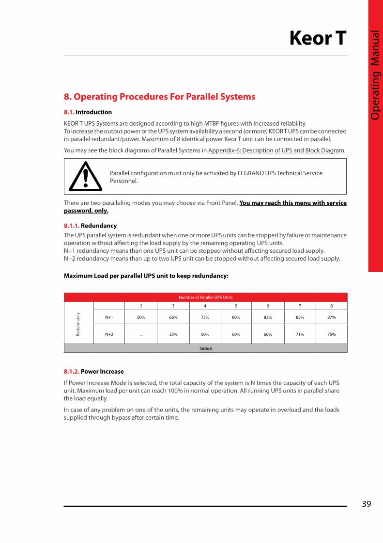
8.1.1. RedundancyThe UPS parallel system is redundant when one or more UPS units can be stopped by failure or maintenance operation without affecting the load supply by the remaining operating UPS units.N+1 redundancy means than one UPS unit can be stopped without affecting secured load supply.N+2 redundancy means than up to two UPS unit can be stopped without affecting secured load supply.
Maximum Load per parallel UPS unit to keep redundancy:
Parallel configuration must only be activated by LEGRAND UPS Technical Service Personnel.
8.1.2. Power Increase
If Power Increase Mode is selected, the total capacity of the system is N times the capacity of each UPS unit. Maximum load per unit can reach 100% in normal operation. All running UPS units in parallel share the load equally.
In case of any problem on one of the units, the remaining units may operate in overload and the loads supplied through bypass after certain time.
Number of Parallel UPS Units
2 3 4 5 6 7 8
N+1 50% 66% 75% 80% 83% 85% 87%
N+2 ... 33% 50% 60% 66% 71% 75%
Table.8
Redu
ndan
cy
40
CAUTION: Do not remove the communication cables between the UPS’s during parallel operation.
In case the communication cable is removed or damaged during parallel operation and the communication is lost then the slave UPS which cannot communicate with the master UPS will disconnect from the output bus and turn off. The other UPSs will continue normal operation. In such a case, this UPS should be turned off completely in order to insert its communication cable again and then switched on again.
Start up for “PARALLEL” UPSs not on Maintenance Bypass Mode;1. Switch the auxiliary supply circuit breaker on the distribution panel to “ON” position. 2. Switch the mains supply circuit breaker on the distribution panel to “ON” position. 3. Switch Q4 (Auxiliary Supply) circuit breakers of all UPSs “ON” position.4. Switch Q1 (Mains Supply) circuit breakers of all UPSs to “ON” position. 5. Switch Q6 (Inrush) circuit breakers of all UPSs to “ON” position.6. Touch Battery icon to see Battery / DC menu measurement. Do not close the battery circuit breakers (F5) until the difference between DC bus and Battery voltages decreases below 10V.7. If exists, switch external Battery circuit breaker to “ON” position.8. Switch Q2 (Output) circuit breakers of all UPSs to “ON” position. 9. If exists, switch the output circuit breakers on the distribution panel to “ON” position (o unit output switch and OS General Output switch).Start up for “PARALLEL” UPSs on Maintenance Bypass Mode;1. Switch Q4 (Auxiliary Supply) circuit breakers of all UPSs “ON” position.2. Switch Q1 (Mains Supply) circuit breakers of all UPSs to “ON” position. 3. Switch Q6 (Inrush) circuit breakers of all UPSs to “ON” position. 4. LCDs will be ON. See “M. Bypass Mode” written on LCD of all UPS.5. Touch Battery icon to see Battery / DC menu measurement. Do not close the battery circuit breakers (F5) until the difference between DC bus and Battery voltages decreases below 10V. 6. If exists, switch external Battery circuit breakers to “ON” position.7. Switch F5 (Battery) circuit breakers of all UPSs to “ON” position.8. Switch Q2 (Output) circuit breakers of all UPSs to “ON” position. 9. If exists, switch the output circuit breakers on the distribution panel to “ON” position (o unit output switch and OS General output switch).10. Switch Q3 (Maintenance Bypass) circuit breakers of all UPSs to “OFF” position. 11. If exists, Switch Q ( External Maintenance Bypass) circuit breaker to “OFF” position. 12. See “Online Mode” written on LCDs
8.2. Procedure for Commissioning and Start-Up
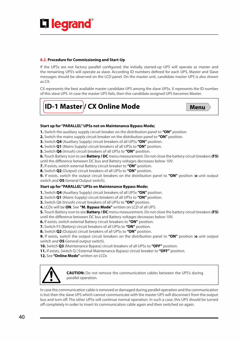
If the UPSs are not factory parallel configured; the initially started-up UPS will operate as master and the remaining UPS’s will operate as slave. According ID numbers defined for each UPS, Master and Slave messages should be observed on the LCD panel. On the master unit, candidate master UPS is also shown as CX.
CX represents the best available master candidate UPS among the slave UPSs. X represents the ID number of this slave UPS. In case the master UPS fails, then this candidate assigned UPS becomes Master.
ID-1 Master / CX Online Mode Menu

41
Keor T
Ope
ratin
g M
anua
l
CAUTION: Do not try to insert its communication cable while it is operating.
The Redundancy System expects to have at least one more UPS than N value. Otherwise it shall provide “Redundancy Lost” alarm. The same alarm shall also appear in case: Load % x (N+1) / N > 100 situation.
8.3. Procedure for DecommissioningDecommissioning “PARALLEL” UPS without switching to Maintenance Bypass Mode; 1. If exists, switch the output circuit breakers on the distribution panel to “OFF” position (o unit output switch and OS General Output switch).2. Switch Q2 (Output) circuit breakers of all Slave to “OFF” position. 3. Switch Q2 (Output) circuit breaker of Master to “OFF” position. 4. Switch F5 (Battery) circuit breakers of all Slave to “OFF” position. 5. If exists, switch external Battery circuit breakers of all Slave to “OFF” position.6. Switch F5 (Battery) circuit breaker of Master to “OFF” position. 7. If exists, switch external Battery circuit breaker of Master to “OFF” position.8. Switch Q6 (Inrush) circuit breakers of all Slave to “OFF” position. 9. Switch Q6 (Inrush) circuit breaker of Master to “OFF” position. 10. Switch Q1 (Mains Supply) circuit breakers of all Slave to “OFF” position.11. Switch Q4 (Auxiliary Supply) circuit breakers of all Slave to “OFF” position.12. Switch Q1 (Mains Supply) circuit breaker of Master to “OFF” position. 13. Switch Q4 (Auxiliary Supply) circuit breaker of Master to “OFF” position.Decommissioning “PARALLEL” UPS with switching Maintenance Bypass Mode;1. Go to Commands menu of Master UPS, enter User password (1111). 2. In page Priority, select Bypass Mode, save and confirm, go back to Energy Flow Diagram screen.3. Check that UPS is in Bypass Mode operation. See all UPSs switch to Bypass Operation. 4. If exists, Switch Q (External Maintenance Bypass) circuit breaker to “ON” position and keep internal Maintenance Bypass Q3 circuit breakers of all units to “OFF” position.5. If External Maintenance Bypass Q is not present , then Switch Q3 (Maintenance Bypass) circuit breakers ofall Slave to “ON” position , then Switch Q3 (Maintenance Bypass) circuit breaker of Master to “ON” position.6. If exists, switch the output circuit breakers on the distribution panel to “OFF” position (o unit output switch and OS General Output switch).7. Switch Q2 (Output) circuit breakers of all Slave to “OFF” position. 8. Switch Q2 (Output) circuit breaker of Master to “OFF” position. 9. Switch F5 (Battery) circuit breakers of all Slave to “OFF” position. 10. If exists, switch external Battery circuit breakers of all Slave to “OFF” position.11. Switch F5 (Battery) circuit breaker of Master to “OFF” position. 12. If exists, switch external Battery circuit breaker of Master to “OFF” position.13. Switch Q6 (Inrush) circuit breakers of all Slave to “OFF” position. 14. Switch Q6 (Inrush) circuit breaker of Master to “OFF” position. 15. Switch Q1 (Mains Supply) circuit breakers of all Slave to “OFF” position. 16. Switch Q4 (Auxiliary Supply) circuit breakers of all Slave to “OFF” position.17. Switch Q1 (Mains Supply) circuit breaker of Master to “OFF” position. 18. Switch Q4 (Auxiliary Supply) circuit breaker of Master to “OFF” position.

42
9. Troubleshooting
The aim of this chapter is to identify potential isues, understand the root cause of the problems and provide solution to them.
9.1. Bypass Voltage Failure AlarmIt means that auxiliary mains supply voltage is out of the limit.Make sure that the auxiliary mains supply circuit breaker is “ON” and the voltage / frequency is between the bypass limit.9.2. Bypass Phase Sequence Wrong AlarmIt means that phase sequence of auxiliary mains supply voltage is not OK. Phase sequence of the auxilary mains supply should be changed. Please contact the LEGRAND Technical Assistance Center.9.3. Inverter not sync. with bypass AlarmFrequency of auxiliary mains supply voltage is beyond the frequency range for online operation or auxiliary mains supply voltage is out of limit. Check if the auxilary mains supply voltage is in specified limits.9.4. Input phase sequence wrong AlarmIt means that phase sequence of common mains supply voltage is not OK. Phase sequence of common mains supply input should be changed. Please contact the LEGRAND Technical Assistance Center.9.5. Rectifier Not Sync. With Input AlarmFrequency of common mains supply voltage is beyond the frequency range of rectifier or common mains supply voltage is out of limit. Check if common mains supply is in specified limits.9.6. Dc Voltage Failure AlarmsAny of the DC bus voltages is out of the limit. If you encounter this alarm during start-up, check if the inrush circuit breaker is at “ON” position. Check polarity of external battery connections if any. If it still exists contact the LEGRAND Technical Assistance Center.9.7. ESD active AlarmIt means that Emergency Switching Device (ESD) is activated (digital input “UPS OFF” is set high). Check if ESD switch is ON or not.9.8. Ambient temperature high AlarmIt is shown “Ambient temperature high” on Diagnostics Menu. If the ambient temperature is high, it causes a rise in the internal temperature of UPS and this alarm appears. In this case; the first thing to do is cool the environment. 9.9. Overload AlarmsLoads connected to the output of the UPS exceed the nominal power of the unit so it gives “Rectifier overload” and/or “Output overload” alarms. Check if there is an overload and origin, remove the excessive load. Hence the alarm would switch to off.
Residual voltage and high temperature metal parts inside even if the UPS is disconnected. Contact may cause electric shock and burns. All operations except replacing battery fuses shall be carried out by the authorized Legrand UPS Technical Service Personnel only.
Make sure that the UPS is not overloaded to provide a higher quality supply to the loads.

43
Keor T
Ope
ratin
g M
anua
l
9.10. Maintenance Bypass Active Alarm
If Maintenance Bypass circuit breaker is brought to “ON” position, this alarm appears. Refer to Section 7.5 to check if Maintenance Bypass decommissioning procedure has been respected.
9.11. Battery test failure Alarm
UPS tests the batteries periodically. In case the batteries failed in the battery test, this alarm appears. Perform the test again when the batteries have been charged for min. 10 hours and verify the battery circuit breaker is at “ON” position. If the alarm continues, contact to Legrand UPS Technical Service.
9.12. Input Voltage Failure Alarms If the input voltage is not in specified limits, these alarms appear and In this case UPS operates in Battery Operation mode. As soon as the mains voltage returns to specified limits, the alarms will dissappear.
9.13. Inverter Temperature High/ Rectifier Temperature High Alarms If temperature of the inverter or rectifier block rises, these alarms appear. The reasons can be: overload, fan failure, high ambient temperature, and dusty environment. If fans failed or any other problem is identified, contact Legrand UPS Technical Service. If any other alarm occurs or if the above alarms cannot be cleared, contact Legrand UPS Technical Service.
Please prepare the following information before you contact Legrand UPS Technical Service:
• Ensure you read and apply troubleshooting procedure carefully • UPS Model Type• Serial Number• Firmware version • Date of failure or problem• Date of commissionning• Symptoms of failure or problem• Customer site address and contact information• Service contract references if any

44
10. Preventive Maintenance
All the maintenance operations should be done by authorized LEGRAND UPS Technical Service Personnel.
Residual voltage and high temperature metal parts inside even if the UPS is disconnected. Contact may cause electric shock and burns. All operations except replacing battery fuses shall be carried out by the authorized LEGRAND UPS Technical Service Personnel only.
10.2. Battery Fuses
There is a risk to blow battery fuses if the battery circuit breaker is closed when the difference between Battery Voltage and DC Voltage is exceeding 10VDC.Please check commissioning procedure in Section 7.
Battery fuses should only be replaced with the same rating and type.
Do not open or mutilate batteries. Released electrolyte is harmful to the skin and eyes. It may be toxic.
Batteries should always be replaced by authorized LEGRAND UPS Technical Service Personnel. Danger of explosion and fire if incorrect battery type is used.Risk of electrical shock, injuries and chemical hazard, lethal voltage present.When replacing batteries, the same quantity and type that were originally fitted should be used.
Batteries must always be disposed of according to local environmental laws.
Preventive Maintenance includes extended control of all the electronic and mechanical components in UPS and permits to replace components before their end of life to assure optimum availability of your UPS system for your critical load.Periodic maintenance also ensures safe and efficient operation of your UPS system.LEGRAND recommends a minimum yearly periodic maintenance visit by authorized LEGRAND UPS Technical Service.
10.1. BatteriesThe life of batteries strongly depends on the usage and environmental conditions. (ambient temperature, frequency of mains outage, etc.). There are also other factors like the number of charge-discharge cycles and discharge depth. Performing battery test can provide you information about battery health condition, but not to avoid any risk of battery failure during mains outage.The batteries should be maintained and checked periodically by authorized LEGRAND UPS Technical Service Personnel and replaced before their end of life.

45
Keor T
Ope
ratin
g M
anua
l
10.3. Fans
The life of fans used to cool the power circuits depends on the usage and environmental conditions (temperature, humidity, dust, pollution)Please look at Appendix-4 Technical Specifications for detailed environment conditions.Preventive maintenance and replacement before end of life shall be done by authorized LEGRAND UPS Technical Service Personnel periodically.
10.4. CapacitorsThe life of the DC electrolytic capacitors and AC filter capacitors used for output and input filtering purposes depends on the UPS usage and environmental conditions.Preventive maintenance and replacement before end of life shall be done by authorized LEGRAND UPS Technical Service Personnel periodically.
46
No Alarms Description
1 Bypass voltage failure Bypass voltage is out of the limit
2 Bypass phase sequence wrong Phase sequence of bypass mains voltage is not OK
3 Inverter not sync. with bypass Frequency of bypass voltage is beyond the frequency range for online operation or bypass voltage is out of limit.
4 Battery breaker open Battery fuses blown or breaker opened by user
5 Battery test failure Battery failure
6 Rectifier temperature high Rectifier IGBT module temperature high
7 Rectifier overload RMS current drawn from any of the input lines exceeds its nominal value.
8 Rectifier communication lost Front panel can not communicate with rectifier
9 Input voltage failure Input voltage is out of the limit
10 Input phase sequence wrong Phase sequence of input mains voltage is not OK
11 Rectifier not sync. with input Frequency of input mains voltage is beyond the frequency range of rectifier or input mains voltage is out of limit.
12 Rectifier not precharged DC voltage not charged by inrush circuit
13 DC voltage failure DC Bus voltage is out of the limit
14 Inverter temperature high Inverter IGBT module temperature high
15 Output overload RMS current drawn from any of the output lines exceeds its nominal value.
16 Inverter DC component high Inverter voltage’s DC component is out of the limit
17 Inverter communication lost Front panel can not communicate with inverter
18 Output DC component high Output voltage’s DC component is out of the limit
19 Output voltage failure Output voltage is out of the limit
20 Output short circuit Short circuit at the output
21 Master communication lost Slave cannot communicate with master
22 Slave not sync. with master Slave lost the synchronization with the master
23 N number failure Parallel UPS count is below the adjusted N number
24 Redundancy lost Parallel system alarm. The total load is more than the redundancy load. The formula is : Load % > N / (N+1) * 100
Appendix-1: Alarms List

47
Keor T
Ope
ratin
g M
anua
l
Appendix-2: Diagnostics List
No Diagnostics Description
1 Bypass active UPS is on Bypass operation.
2 Bypass blocked Bypass is blocked by UPS
3 Bypass disabled Bypass is disabled by user
4 Eco mode active Eco mode is selected
5 Battery test active Battery test is running now
6 Battery discharging Rectifier overload and can not feed DC enough or mains failure
7 Ambient temperature high Ambient temperature exceeds the upper limit
8 Rectifier passive Rectifier is not running now
9 Rectifier blocked Rectifier is blocked by UPS
10 Rectifier disabled Rectifier is disabled by user
11 Inverter passive Inverter is not running now
12 Inverter blocked Inverter is blocked by UPS
13 Inverter disabled Inverter is disabled by user
14 Generator mode active Generator friendly operation is activated
15 ESD active Emergency Switching Device interface is activated
16 Maintenance bypass active Maintenance bypass switch is at “ON” position
17 Output breaker open Output circuit breaker is at “OFF” position

48
No Events Description
1 Bypass voltage ok Bypass voltage is within its limit.
2 Inv. sync. with Byp. Frequency of bypass mains voltage synchronized with output frequency.
3 Byp. ph. seq. ok Phase sequence of bypass mains voltages is OK.
4 M. Bypass passive Manual bypass switch is at “0” position.
5 Inverter temp. ok Inverter block temperature is within the limits.
6 Inverter load ok RMS current drawn from any of the output lines does not exceed its nominal value.
7 Bypass passive Bypass does not operate now.
8 Inverter active Inverter operates now.
9 Output voltage ok Output voltage is within the limits.
10 Master com. ok There is no communication problem with master UPS.
11 Input voltage ok Input voltage is within the limits.
12 Rec. sync. with Inp. Rectifier is synchronized to input frequency.
13 Inp. ph. seq. ok Phase sequence of input voltages is OK.
14 Rectifier temp. ok Rectifier block temperature is within the limits.
15 Rectifier load ok RMS current drawn from any of the input lines does not exceed its nominal value.
16 DC voltage ok DC bus voltage is within the limits.
17 DC voltage ok DC bus voltage is within the limits.
18 Rectifier active Rectifier operates now.
19 Output breaker closed Output circuit breaker is at “I” position.
20 Batt. test completed Battery test is completed.
21 Redundancy ok All parallel UPS are OK.
22 N number ok All parallel UPS are OK.
23 Rectifier enabled Rectifier enabled is set as “YES” from front panel.
24 Inverter enabled Inverter enabled is set as “YES” from front panel.
25 Bypass enabled Bypass enabled is set as “YES” from front panel.
26 Eco mode passive Eco Mode enabled is set as “NO” from front panel.
27 Batt. not discharging Battery is not discharging.
28 Ambient temp. ok Ambient temperature is within the limits.
29 Gen. mode passive Generator friendly operation is passive.
30 ESD incactive Emergency Switching Device interface is inactive.
31 Battery test succeed Battery test result is success.
32 Battery breaker closed Battery circuit breaker is at “I” position.
33 Rec. precharged DC bus voltage is equal to input voltage.
34 Inverter com. ok Communication between the inverter and the front panel is OK.
35 Rectifier com. ok Communication between the rectifier and the front panel is OK.
36 Bypass voltage high Bypass voltage is higher than its limit.
37 Bypass voltage low Bypass voltage is lower than its limit.
38 Inv. not sync. with Byp. Frequency of bypass mains voltage not synchronized with output frequency.
39 Byp. ph. seq. wrong Phase sequence of bypass mains voltages is not OK
40 M. Bypass active Manual bypass switch is “ON”
41 Inverter temp. high Inverter block temperature is very high.
Appendix-3: Event List

49
Keor T
Ope
ratin
g M
anua
l
42 Inverter overload RMS current drawn from any of the output lines exceeds its nominal value.
43 Bypass active UPS is on Bypass Operation.
44 Inverter passive Inverter does not operate now.
45 Output voltage failure Output voltage is beyond its limits
46 Master com. lost This alarm is observed when information flow from master ups is interrupted
47 Input voltage high Input voltage is higher than its limit.
48 Input voltage low Input voltage is lower than its limit.
49 Rec. not sync. with Inp. Frequency of input voltage is beyond the frequency range for bypass operation or bypass mains voltage is very low
50 Inp. ph. seq. wrong Phase sequence of input mains voltages is not OK.
51 Rectifier temp. high Rectifier block temperature is very high.
52 Rectifier overload RMS current drawn from any of the input lines exceeds its nominal value.
53 DC voltage high DC bus voltages are higher than its upper limit.
54 DC voltage low DC bus voltages are lower than its lower limit.
55 Rectifier passive Rectifier does not operate now.
56 Output breaker open Output Circuit Breaker is at “OFF” position.
57 Batt. test active Battery test is on progress.
58 Redundancy lost Parallel system alarm. The total load is more than the redundancy load. The formula is : Load % > N / (N+1) * 100
59 N number failure Parallel system alarm. If the UPS number in parallel is less than the preadjusted N number, that alarm appears.
60 Rectifier disabled Rectifier enabled is set as “NO” from front panel.
61 Inverter disabled Inverter enabled is set as “NO” from front panel.
62 Bypass disabled Bypass enabled is set as “NO” from front panel.
63 Eco mode active Eco Mode enabled is set as “YES” from front panel.
64 Batt. discharging Battery is discharging.
65 Ambient temp. high Ambient temperature exceeds its upper limit.
66 Gen. mode active Generator friendly operation is activated.
67 ESD active Emergency Switching Device interface is activated.
68 Battery test failure Batteries failed in the battery test.
69 Battery breaker open Battery Circuit Breaker is at “OFF” position.
70 Rec. not precharged DC bus voltage is not equal to input voltage.
71 Inverter com. lost Communication between the inverter and the front panel is lost.
72 Rectifier com. lost Communication between the rectifier and the front panel is lost.

50
Appendix-4: Technical Specifications
Tower Model (3Ph/3Ph) KEOR T 10KVA
KEOR T 15KVA
KEOR T 20KVA
KEOR T 30KVA
KEOR T 40KVA
KEOR T 60KVA
KEOR T 80KVA
KEOR T100KVA
KEOR T 120KVA
Output Power (VA) 10.000 15.000 20.000 30.000 40.000 60.000 80.000 100.000 120.000
Nominal Active Power (W) 9.000 13.500 18.000 27.000 36.000 54.000 72.000 90.000 108.000
Rectifier Input
Nominal Voltage 400V (Ph-Ph) 3Ph+N+PE
Input Voltage Range (VAC) (at 50% Load) 208-459V
Input Voltage Range (VAC) (at full Load, with battery charging) ±15%
Frequency (Hz) 45 - 65
Power Factor ≥ 0.99
Bypass Input
Nominal Voltage 400V (Ph-Ph) 3Ph+N+PB
Voltage Tolerance ±18% (Customizable)
Frequency Tolerance (Hz) ±3
Transfer Time (ms) <1
Output
Nominal Voltage (VAC) (Ph-Ph) 400V (Ph-Ph) 3Ph+N+PB (380/415 Adjustable)
Power Factor 0.9
Wave Form Sinusoidal
Frequency (Hz) 50 or 60 (Adjustable)
Frequency Tolerance (Battery Operation) 0.01%
Voltage Regulation (Static) ±1%
Output voltage unbalance at reference unbalance load
<0.5%
Maximum phase angle variation <0.10
Crest Factor 3:1
Nominal Power (kVA) 10 15 20 30 40 60 80 100 120
Overload Protection (sec) 600 (at 100 - 125% Load)60 (at 125 - 150% Load)
THDV
< 2%Non-Linear Load < 4%
Battery
Battery Type Maintenance-Free Lead Acid Batteries
Battery String (Blocks) 1x60
Protection
Overload Protection, High Temperature, Input Over Voltage, Input & Output Over Current, Back-Feed Protection,
Intelligent Charging Algorithm - Deep Charge Protection - Battery Test (Automatic / Manual), Short-Circuit Protection

51
Keor T
Ope
ratin
g M
anua
l
Communication*Standard Interface RS232, ESD, Genset, Modbus, 4 Programmable Relay Contacts
Options USB Converter, SNMP
Environment
Operating Temperature Range (⁰C) 0 - 40
Battery Temperature Range (⁰C) 20 - 25 (Recommended For Longer Battery Life)
Maximum Altitude without Derating (m) 1000
Relative Humidity Range 20-95% (Non-Condensing)
Acoustic Noise (dBA) < 55 (at 1m)
Pyhsical
Dimensions (HxWxD) (mm) 1345/1650 x 400 x 800 1650 x 600 x 900 1650 x 600 x 800 1650 x 600 x 900
Weight (kg) (without battery & transformer) 121 / 140 132/151 144/162 148/169 241 276 317 348 365
Paint RAL 7016@enclosureRAL 9005@front door metal
Standards
Safety IEC/EN 62040-1
EMC IEC/EN 62040-2
Performance IEC/EN 62040-3
Design IEC/EN 62040ISO 9001:2008 - ISO 14001:2004
Protection IP 20 (other IP as option)
Options
Galvanic Isolation Transformer (Internal for 10-60kVA, External for 80-120kVA (on request))
* Please contact Legrand or your local authorized distributor for optional communication interfaces.** The manufacturer reserves the rights to change the Technical Specifications and design without notice.
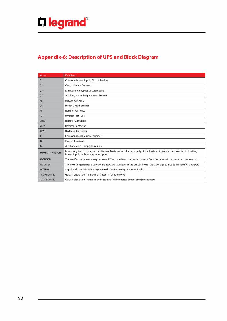
52
Appendix-6: Description of UPS and Block Diagram
Name Definition
Q1 Common Mains Supply Circuit Breaker
Q2 Output Circuit Breaker
Q3 Maintenance Bypass Circuit Breaker
Q4 Auxiliary Mains Supply Circuit Breaker
F5 Battery Fast Fuse
Q6 Inrush Circuit Breaker
F1 Rectifier Fast Fuse
F2 Inverter Fast Fuse
KREC Rectifier Contactor
KINV Inverter Contactor
KBYP Backfeed Contactor
X1 Common Mains Supply Terminals
X2 Output Terminals
X4 Auxiliary Mains Supply Terminals
BYPASS THYRISTOR In case any inverter fault occurs; Bypass thyristors transfer the supply of the load electronically from inverter to Auxiliary Mains Supply without any interruption.
RECTIFIER The rectifier generates a very constant DC voltage level by drawing current from the input with a power factor close to 1.
INVERTER The inverter generates a very constant AC voltage level at the output by using DC voltage source at the rectifier’s output.
BATTERY Supplies the necessary energy when the mains voltage is not available.
T1 OPTIONAL Galvanic Isolation Transformer (Internal for 10-60kVA)
T2 OPTIONAL Galvanic Isolation Transformer for External Maintenance Bypass Line (on request)

53
Keor T
Ope
ratin
g M
anua
lSEPARATED RECTIFIER AND BYPASS INPUTS FOR SINGLE UPS UNIT (10-60kVA)

54
SEPARATED RECTIFIER AND BYPASS INPUTS FOR SINGLE UPS UNIT (80-120kVA)

55
Keor T
Ope
ratin
g M
anua
lCOMMON RECTIFIER AND BYPASS INPUTS FOR SINGLE UPS UNIT (10-60kVA)

56
COMMON RECTIFIER AND BYPASS INPUTS FOR SINGLE UPS UNIT (80-120kVA)

57
Keor T
Ope
ratin
g M
anua
lTWO PARALLEL UNITS 1+1 Redundant Configuration with Dual Distribution Input (10-60kVA)
a1, a2: Mains Supply MCCB 4pd: Distribution MCCB b1, b2: Auxiliary Supply MCCB 4po1, o2, unit output switch 4p
NOTE :Q3= Internal Maintenance Bypass can be used when total load < single unit rating (kVA) Option o1, o2= unit output disconnect switch to enable single unit complete shut down for maintenance a, b, o should be 4poles unless TN-C distribution is usedIn case we have parallel system with internal transformer; it is recommended to install output switches (o) to enable sequential energizing of the different transformers.

58
TWO PARALLEL UNITS 1+1 Redundant Configuration with Dual Distribution Input (80-120kVA)
a1, a2: Mains Supply MCCB 4pd: Distribution MCCB b1, b2: Auxiliary Supply MCCB 4po1, o2, unit output switch 4p
NOTE :Q3= Internal Maintenance Bypass can be used when total load < single unit rating (kVA) Option o1, o2= unit output disconnect switch to enable single unit complete shut down for maintenance a, b, o should be 4poles unless TN-C distribution is used

59
Keor T
Ope
ratin
g M
anua
lTWO PARALLEL UNITS 1+1 Redundant Configuration with Single Distribution Input (10-60kVA)
a1, a2: Mains Supply MCCB 4pd: Distribution MCCB o1, o2 unit output switch 4p
NOTE:Q3= Internal Maintenance Bypass can be used when total load < single unit rating (kVA) Option o1, o2= unit output disconnect switch to enable single unit complete shut down for maintenance a, o should be 4poles unless TN-C distribution is used
In case we have parallel system with internal transformer; it is recommended to install output switches (o) to enable sequential energizing of the different transformers.

60
TWO PARALLEL UNITS 1+1 Redundant Configuration with Single Distribution Input (80-120kVA)
a1, a2: Mains Supply MCCB 4pd: Distribution MCCB o1, o2 unit output switch 4pNOTE:Q3= Internal Maintenance Bypass can be used when total load < single unit rating (kVA) Option o1, o2= unit output disconnect switch to enable single unit complete shut down for maintenance a, o should be 4poles unless TN-C distribution is used

61
Keor T
Ope
ratin
g M
anua
lTHREE PARALLEL UNITS N+1 Redundant Configuration with Dual Distribution Input (10-60kVA)
a1, a2, a3: Mains Supply MCCB 4pb1, b2, b3: Auxiliary Supply MCCB 4pd: Distribution MCCB o1, o2, o3 unit output switch 4pOS: General output switch 4pQ: External Maintenance Bypass MCCB 4p NOTE:Q= External Maintenance Bypass MCCBOS = general output disconnect switchRating = N X unit rating (kVA) Internal Maintenance Bypass Q3 cannot be used should be locked to avoid any misuse.Option o1, o2, o3= unit output disconnect switch to enable single unit complete shut down for maintenancea, b, o, OS, Q should be 4poles unless TN-C distribution is usedIn case we have parallel system with internal transformer; it is recommended to install output switches (o) to enable sequential energizing of the different transformers.

62
THREE PARALLEL UNITS N+1 Redundant Configuration with Dual Distribution Input (80-120kVA)
a1, a2, a3: Mains Supply MCCB 4pb1, b2, b3: Auxiliary Supply MCCB 4pd: Distribution MCCB o1, o2, o3 unit output switch 4pOS: General output switch 4pQ: External Maintenance Bypass MCCB 4p NOTE:Q= External Maintenance Bypass MCCBOS = general output disconnect switchRating = N X unit rating (kVA) Internal Maintenance Bypass Q3 cannot be used should be locked to avoid any misuse.Option o1, o2, o3= unit output disconnect switch to enable single unit complete shut down for maintenance a, b, o, OS, Q should be 4poles unless TN-C distribution is used

63
Keor T
Ope
ratin
g M
anua
lTHREE PARALLEL UNITS N+1 Redundant Configuration with Single Distribution Input (10-60kVA)
a1, a2, a3: Mains Supply MCCB 4pd: Distribution MCCB o1, o2, o3 unit output switch 4pOS: General output switch 4pQ: External Maintenance Bypass MCCB 4p NOTE:Q = External Maintenance By pass MCCB OS = general output disconnect switchRating = N X unit rating (kVA) Internal Maintenance Bypass Q3 cannot be used should be locked to avoid any misuse.Option o1, o2, o3= unit output disconnect switch to enable single unit complete shut down for maintenance a, o, OS, Q should be 4poles unless TN-C distribution is usedIn case we have parallel system with internal transformer; it is recommended to install output switches (o) to enable sequential energizing of the different transformers.
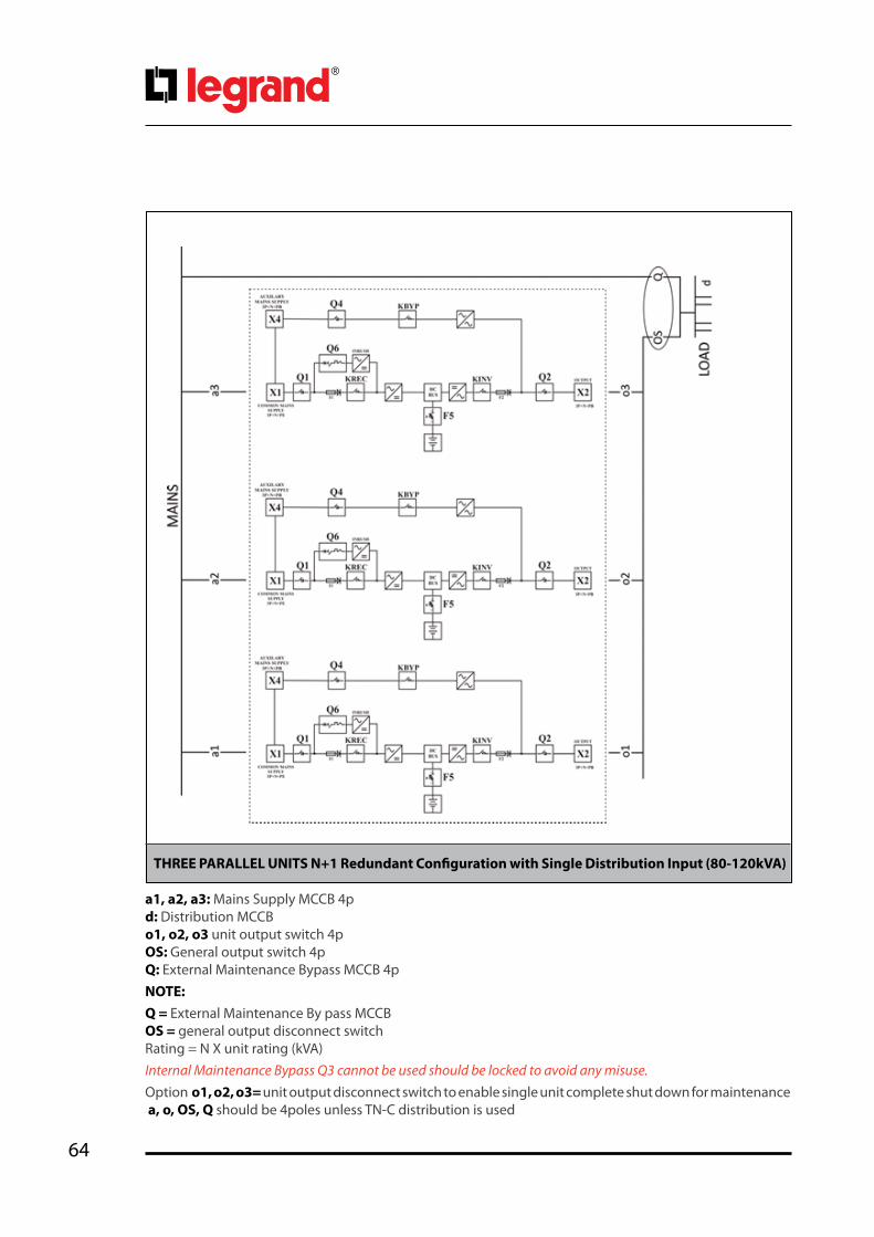
64
THREE PARALLEL UNITS N+1 Redundant Configuration with Single Distribution Input (80-120kVA)
a1, a2, a3: Mains Supply MCCB 4pd: Distribution MCCB o1, o2, o3 unit output switch 4pOS: General output switch 4pQ: External Maintenance Bypass MCCB 4p NOTE:Q = External Maintenance By pass MCCB OS = general output disconnect switchRating = N X unit rating (kVA) Internal Maintenance Bypass Q3 cannot be used should be locked to avoid any misuse.Option o1, o2, o3= unit output disconnect switch to enable single unit complete shut down for maintenance a, o, OS, Q should be 4poles unless TN-C distribution is used


LEGRANDPro and Consumer ServiceBP 30076 - 87002LIMOGES CEDEX FRANCEwww.legrand.com
Legrand reserves at any time the right to modify the contents of this booklet and to communicate,in any form and modality, the changes brought to the same.
Installer stamp
Figure.5.3.2-3