kepco power supply. news - the library of...
TRANSCRIPT

•
•
KEPCO POWER SUPPLY. o l atest Information on the development and applicatio n of Voltage/Current Regulated Power Supplies . news
KEP C O . In c, • 131 -38 Sanfo rd Ave ,. Flush;ng. N, Y 11352 . Phon e : (2 12) I N 1-7000 • TWX 710-582-2631 • Cabl e: K EP COP OWER NEW YO RK
VOLUME 11 , NUMB ER 146-1167 ! KEPCO , In c , 1967
KEPCO-MIDWEST SEMINAR ON TOUR
Mldwesl ' s Bernie Menarik discusses th e prog ra mm ing cap abi li ti es of the basic Kep co Cont ro l Brid ge w ith a sem in a r gro up .
~I i clll e~ t Electronic S ~l cs. Kepco's re presc nt~til'es fo r So uth Wi sconsin . Ea stern 10 11' ,1, l'!orth ern Illin ois . Indi nlLl. ~ nd Kentuckt- , has del 'C lopcd a I'erl' success ful "on tlt e spot" in
plant I.:: epco Semin a r Il l"Ogram , Alth ough rece ntit' inaugurated, these selllinJr~ hal 'e a lrcml l' achi el'ed consiclerable popul ,)l'ilt ' Il'i th the 01 <1 01 ' industrial , elec tronic and rese<Hch firm s in ~ Iidll'es t' s area , ft brings to iJ) terested tcchn ica l 'llIc1i ences tIle latest opCl'ati on a l control techniques (lctc loped hI' I\e pco II'hich ra n"e far hel'ond the front knob con trol limits mos t cO lllnlO nh' a ss(~' i<lt e d lI;th the use of pOll'cr suppli es, The lectu re material. based on th e I':: epco POll' ('\' Supp" Han d book, is presented in a d ea r and infor matil 'e manner , <1 nd h 'l s prOl'ell ITn useful to engineers and technici ans, Tn f~c t , se l ' er ~t1 unil 'C rsiti cs h~I ' e responrled l'e n ' fa l'Orabh to these i\lidll' est-Kepco Se min ~ r s ,
Contil/lled all Page 4 - Col. J
NEW HIGH-VOLTAGE OPERATIONAL POWER SUPPLY/AMPLIFIER In the nell' BHK Series H igh Voltagc PowerSul'p,," /A lllplili e r. Kepco has c hose n to use a fulk cli ssipati l't' n:gu Lltor dcsi gn , ,\1 though thi s requ ires more p~ ss e lements amI grea ter he;lt di ssipation , b )' avoidin g the usc of un)' pre rcgul Mors, the powcr suppl y is m ade much less restri cted in terms of banchl' idth, di ss ip~ ti on, and output r ange. One kind of p re regulator used p revious lt' to limit d issipation ill [\ e pC(i~ OlIn HB d esign , reli ed on the se lec tion of secondary t ~ ps on th e pOIl' c r t ransformer to kee p the voltage ac ross the pa ss e lemcn l lllinimi /cd , PrilJHlr ik , t he objec til'e, in th e case of the HB desi gn . is to keep the rii ssil'atio ll minimi /ed wh ere tIl e pass tubes arc able to l~ke the voltage, Oth er design methods . include var ia ble auto-tra nsformer track ing, as in the HE 20 50 and the lI B 2500 [lower supplies. ( in which the purpose is to keep the I'O ltage lIi thin
the ca pabiliti es of the pass tubes) . All of these m e thods of prereg ulat ion or di ssi pation control,
ill some lI'a\ limit the Aex ibilitl of the pOIIl' r , upplt , Other Cont inlled 011 Page 2 - C ol. I
THE HI FI POWER SUPPLY I'\: eed an audi o amplifi er ' Faced recently with a requi re ment for a small publi c ~ddres s amplifier , " epco en g in ee rs dec ided to scc lI'hat would h ~ pp c n if they hooked a micro ph one or pllOll O unit input to one of th e nell , fa st sleW ing D C power supplies , The results ; bea utiflJ lmusic l Th e H i Fi POII'c r Suppit·, as it is known , h as been tra\'e ling eve r since , serl' in g as the PA amplifi e r for " e pco's lec t(J re series ( on th e "Op-Amps
with muscle," see EEE Maga zill e. Jun e. 196 6 ),
Thi s \'Oc~ 1 power suppl l' ha s eli c itedmanl' questions from audio-mindeci e ngin ee rs th at we hope th is close-up view will he ll' anSIl 'l' r a nd , perha ps, in spire others, \\'e h al'e no illu sions th at fast s lell'ing power supplies shou ld be p rom oted as auelio ilmplifie rs , but th e banclwith -ga in so illu strated is indicatil'e of th e \'ar ie tl ' o f in strum ent ation tas ks tha t can be handled bl such equipmcnt.
MICROPHONE PR E-AMP PLUG-IN ATTAC HM ENT WITH MODEL PA X 7-1CH S POWER SUPP LY
The I'e rsatililt· of wh ich we speak der ives fro m the power supply's "bilitl' to be eas ily mod ula ted ; th at is, to hal'e its outpu t I' ~ri c d as a linea r fun c tion of inp!lt or comm and Signals. All of l\ epco's p rogramm a bl e DC supplies ha l'e thi s ca pabilitl" Th el' ma ~ ' be moclu lilt eel b y a chan gi ng reSista nce/voltage/ cu rren t and / or co nductance. a nd like operation a l amplifiers , c~n bc m ade to res pond in spec ifiC, pred ictable \I'~I ' S to such ex citation , Dmami calll' , th e usua l pOIl'Cf su pph"s output and fecdback filter-capa citors severcll' limits the bandll'idth of Signa ls th ~ t can be accomm oe1 a tecl. For practical purposes , th e conventional pOlI'er supply is limited to CJ uas i-static p rograms whose d ynamic ra te -of-change d oes not exeeed a fe ll' hund red
l'OltS per second, Cont/Ill/ ed on Page 5 - Col. 1
THE H IFI POWER SUPPLY . . Page t
KEPCO MIDWEST SEMINARS ON TOUR . Page 1
HIGH VOLTAGE POWER SUPPLYjAMPtiFIERS Page t
NEW PRODUCTS FOR '67 , Page 6

HIGH VOLTAGE POWER SUPPLY/AMPLIFIERS
Continued from Page] - Col.
methods which have been used include "the piggy back" design, ( with similar limitations ), and switching prcregul ators,
another pair. The BHK , then, is a unipolar, high I'oltage DC amplifier.
\ Ve have made provision for fast slell';l/g cOI/1/Cet;oIlS, in which the filter capacitors, that are normally used II'h en the power suppll' is functioning as a power supplY, ca n be re
which are semi-conductors in loll' level voltage circuits, moved . The bandwidth of th e unit without the lilter capaci- •
switched on and off at various frcgu encies. This technique tors is large enou gh so that the power suppll' is ex trem ely
produces non-harmonic frequency components in the output, useful as an instrumentatian amplifier.
howcver, which are disadvantageous. For example, from the chart that is reprod uced elsewhere
All of these techniques depend on "trading off" one perin this issue, a 500 ,000 I'olt/second slewing rate with a 100
formance feature for another. "'e have chosen in the new I'olt peak to pcak wave form is capable of 1.6 ke bandwidth, BHK design , a fully di ss ipative route, in which we do not
and at the 10 volt peak to peak level, 16 kc . For a 1 volt peak "trade off" anI' performance at all. Instead, we have dealt di
to pea k excu rs ion, the bandwidth is incrcased to 160 kc. Thi s rectly with th~ problem of heat dissipati on, rather efficiently is a suffici cn tlv wide bandwidth to make the device useful in by using vacuum tube pass elements which opera te at high s ign~l foll o ll'i~ g and proccssi ng applications , and as a quicktempera tures . The heat tra nsfer problem is considerablv less
responding cur rent source, among other poss ible applications. than with transistors , II'here the temperature differen tial be When thc power supply is opera tin g as a current source , tween the dissipating element and the outside temperature it is effectivell' self-programmed. Its voltage will follow the would be relatively small. load rcsis t a nc~s in an automatic fash ion . There fo re , th c user
has to think in terms of the slclVing rate of the output to determine what the recol'erv time of the device 1I'0uld be as a current regulator. In thi; case, the recovery time would be better than 0.5 volt per microseco nd.
As a power supply, fast programmed from one voltage level to another throughout its range, the ability to gct to a nell' volt
TYPICAL REAR VIEW BHK POWER SUPPLIES SHOWING age, and settled at that voltage, is enormously improved by PASS AND CON TROL TERMINALS. this fast slewing ca pability. 1t is possible to step from 0 to 1000
The type 8068 pass tube is particul arly well designed for l'O\tS, for exam ple, in < 2 milliseconds . This by comparison,this kind of service. It has a 3500 volt plate to cathode rating, might take 4 seconds, if th e power supply were functionin g a 35 watt plate dissipation rating, 5200pmhos trans-conduc with its normal ou tput capacitor. tance, and \'ields I'ery high gain. As a matter of fact , the tube The settling time is a function of the dam ping ratio of the gives so much gain in this particular circuit that the overall power suppll'. Provisions are maele to se t it up for an under- • loop gain approaches 120 db, ( although the closed loop gain is damped , O\'erdamped, or critically da mped response. The only specified as > 1OOdb ). This mea ns th at although the meth od that has been provided takes the form of an adjustable power suppll.'s temperature compensated six volt refercnce is fecdback capaci tor in para llelll'itl1 the voltage control. Assum amplified up to the 500,1000, or 2000 volt output level, ( the ing J 1 milliampere control current, a se lection of fixed ceroperational gain , or amplifica tion is better th an 83,167, or amic capacitors , from 50 to 3900 picofarads is prol'ided.333 times, respectil'ely), the rema ining, so-ca lled "loop gain", These can be connected in parallel in various combinations.
FIGURE which determines the regulating capabilit\', will still exceed The range of feedback capacitance is such that it is possible60 db. In order to have a well-regulated high voltagc pOll'er /\ 5 anto set the pOII'cr supply either for an underdampeel state (i n supply, it is obviously necessary to have very high gain Supply-It\\'hich the output voltage overshoots its final va lue, osci llates circuits. gain rat i(on ce or twice about the ultimate valuc and th en settles down),
Rather than letting all this gai n go to waste, we havc de input J' C~a critically damped state, or a conSiderably ol'erdamped st ate signed the BHK power su pply so that there is eOIl\'enient ac in which the I'oltage approaches its fin al va lue in an aSl'mptotic resistaneo cess to all the necessary control points in the circuit . Th e gain J1li croph( fashion . The maximum programming spced occurs when the can be used as thou gh it were an amplifier, with a signal ap sl'stem is some\\·hat underdamped, and ol'ershoots perhaps b\' the 51 plied to a pair of input termin als, and an output taken from cono'nee, and then settles back to its final value. This relationship wa s ~
is treated in man y textbooks on servomechanisms or feedback Supply, ~ Rr FEEDB ACK RESISTOR control sys tems .
r---------,
Ed lNTERNAL REfERENCE)
The BH K powcr supply is also an automatic crossol'cr EXTERNAL power supply. Becau se of its full dissipati on capabi litv, it ha s II I I I I I I + I I I I L _________ ...JI 1 to choose between the Signa l from the voltage am plifier ,m el
~ LinkS IttwOVell bet 'Neen lefllOrnals 1,2, J ~od 7, 14 . the signal from the current amplifier. A VIX ' circuit in the The illo. power supply displa ys the position of the gate on the front rarccl 0
TYPICAL BHK OPERATIONAL AMPLIFIER CONFIGURATION . panel, and also prol'ides a Signal at the rear. In this power gai n am I
2
the ability to operate as a current regulator from zero to its
R, maximum rated output voltage, without anI' current derating EXTERNAL restriction. Consequently, Kepro has built in the automatic INPUT RESISTOR crossover circuit. In effect , we have built-in a full ampifier
to detect the I'o ltage across an internal curren t sampling resistor, produ ci ng a signal proportional to th e output current. There is a complete ga te circuit which allows th e pass tubes •
FIG• "
suppk, the VIX " signal is I 15 V "c. Like all of tile I<epeo autom~tie crosso\'er power suppl ies,
this one cont ai ns a pair of o utput controls o n the f ron t pa nel , a ten-turn I'o ltage controL ami a ten-turn c urrent control. Since tile I'oltage control mu st cover a relative'" wide voltage range, a ten pos ition range sll'itch and ten-turn H'rnier control is proI'ided. In the ca se of th e "Iodd BHI<-I 000-0.2:\1, the r~ngc swi tch h as ten ste ps of 100 volts per stcp , and the 10-turn control need on II, cover a 100 "olt spa n . The current cont rol does n ot ha, e this kind of problem, since it has onll' a fell' hundred milliamperes of ra nge, and is adeljuatell' eo"ercel b,' a singl e 10- turn cont rol. The "oltage control's ste p se lect o r docs not limit the programming of the power supph-. The switch is th ere fo r th e purpose of increas in g the re solution in the settin g of th e ou tput ,'oltage and ~Iso to circuml'ent the problem of supportin g all the output " o ltage across a single contro l. Since all res istors ha\'e a "olt age coefficient, that is to say, th eir resistance ch a nges as a fun c tion of the I'olta ge being supported across their terminals, it is desirab le to keep that vo ltage small, and this the ten position s\\' itc h acco lllplishes. The snitch is //ot doi ng anI" SWitching in the I'ri1l1ar),
or the .IccO Ilr/ar.\' of the tr ansform e rs. It is lIo t in anI" \\, H"
limitin g the dissi pation inside the po\\'er suppl\' , and so it has 110 li11litatioll on th e program ming function of th e pmrer supply, or on its ra nge of oper<3tion ~s a current regulator.
a~z::~ Q f7:l ~~-~-~] c ~.~ lalla} ~,I C)- ~[~-•• ~?;-;_~-:;_":- I ! .. G -... z• FRONT PANEL VIEW MODEL BHK l OOO-O. 2M
The fro nt pane l OUtpllt connectors on the CHI< ore speciall\' des ign ed for safrt l". The" arc recessed , so that a ll accidental contact ca n be minimiLl'd. 1\11 the p rogramming run cti on and output termin a ls nre, of co urse, pro"ided on the b~ck of the su ppJr, behind luc ite safet\' pan els.
The controls \\'hich are prol' ided on the BIl K pO\l'er supp'" arc uniClue in the power supp,," industn' for thei r completeness and I' a riet y. In addition to th e front panel ,'oltage cont ro ls nnd curren t con trols, the designers of th is pO\\'e r sllppll' ha''l' built into it prim arv offse t compensation contro ls, whi ch recognize th e existence of offset r atings, and thei r importa nce. These offse t con trols enable the user to preci sch ' /e ro nil of the no n-idealities of the amplifiers.
Non-idealities can hri enl' bc dividcd into t\\'o parts; the fi xed parts of th e offset \' olt age, and the offset current. In the BHI<, there is a n offset I'oltage adjustment hal'in g a plusminus 120 milli" o lt range. It is a 25 -turn trimmer built into the power suppll . There is an ofrset current compen sa tor haVing a 0-12. microampere rangc, II'hi ch lI'ili lero the offset curren t into the I'oltage a mplifi e r. There' a re a pair of ca librators, whic h e ffecti" elv set the con trol cur re nt, one for ti le I'olt age al11 l, lifier , h a"ing a plus-minus fil' e percent r~nge , a nd the other for the current amplifier, agai n h a"ing <3 plus or minu s fi\'e perce nt range. Both of th em are 2.5- tLirn trimmers ,
There are two adj ustable ,\C lag ne tlrork s, which prm'id e Fur t\C stabilitl', whe n the output li lter c~paci t (J rs are unstrapped for fas t s leWing operatio n . \\'ith the rem Oval o f the capacitors, tbe phase ga in margin of stah ilitl is gre<3 th reduced . To opcra te with out the output capaci tor, it is necessa n to \\'ork into a
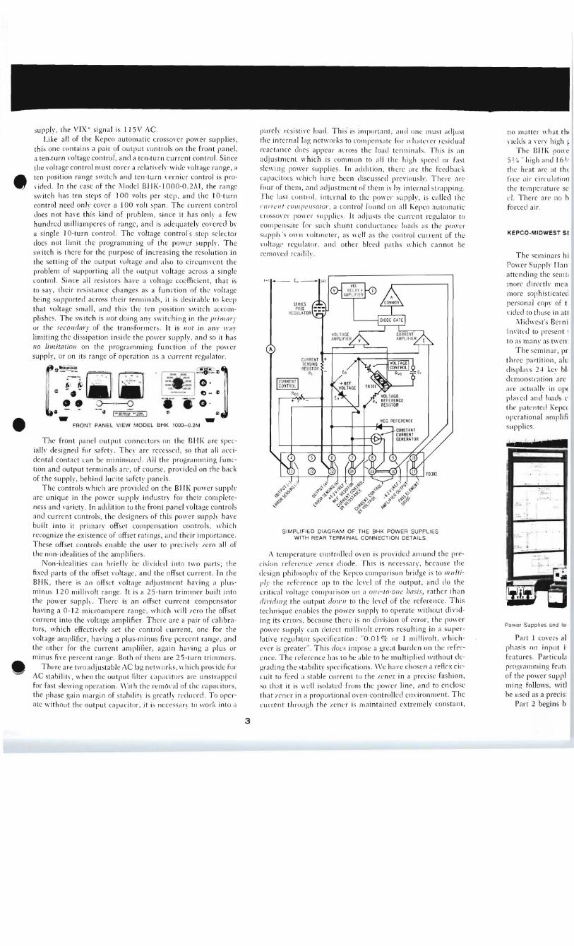
plII'e h ' resi stive 10<3d. Thi s' is il1ll,o rtan t , ,lIld nne must adjust the intern a l lag net\l'orks to compens,ltc for \I'h ate ,'er res.idual reac tan ce docs appear across the load tcrmin " ls. This is an adjustment which is common to a ll the hi gh speed or fast sle \\ 'ing po\\'er supplies, fn add iti on, th ere arc the feedback ca pacitors ,rhic h hil" e been di scussed pre"iouslv. There arc four of them, ,md adj us tment or thelll is 1)\ internal strapp ing. The las t con trol, internal to the ]lOl\'l'r supph', is Cil lled the "II/Tell t l'()l1/I'l'lI sntor, a con trol round on nil f.:epco automatic crosso , 'er po\\'('r suppli cs. It adjusts the current regul ator to
eompcnsa te [01' su ch sh unt condu ctance loads as tIll' penH'r ,upI'll' 's mrn mltmeter, as \\TlI as the cont..-ol current of the m ilage' regulator, and other bleed paths \\·hi ch cannot be remol'ed readil",
+
SIMPLIFIED DIAGRAM OF THE BHK POWER SUPPLIES WITH REAR TERMINAL CONNECTION DETAILS.
i\ tel1lperntu re controlled m'en is prOl"idcd around th e precis ion refe rence /enl'l' diode, This is necessary, because the d es ign philosopl1\' of the l< e]1('O comparison bridge is to 111l11ti1'1.1' the re f'crence up to the le"el of the () ul[JUt , and d o the critical , 'o lt aoe com par ison un ,I Vll e-I() -O IlL' "miS, rath er than riil ' ir/ illg th e ~)utput riVlI'lI to the !e1'c1 of the re feren ce, Thi s technique ena bles th e powe r supply to opera te without (Jj"id in g its errors, beca use th ere is no d ivisi o n of error, the pO\\ 'er po\\'e>r supph' ca n det cc t millil'olt errors resultin g in a superlilti" e regulator specificJtion : "0. 0 I o/c or I m illivo lt , whi c hever is grrate r". Th is r/()C S impose a gre<lt burden on the refl'rence, Th e re Fe re nce hn s to be able to be multiplied ll'ith out degra din g the stabi lity spec ifications , We ha l'c choscn a re Ae x circuit to feed a stabl e current to the I.cn('[ in a precise fas),ion, so tha t it is '\'l, 1I isobteel from the power line , anei to enclose th a t I c/wr in it proportional ()I"en-controll ed environment, The current through th e I.cner is maintained extremel" constant ,
no m att er \\ 'ha t th,
'iclds a "el"\' hi gh ~ The Cll" po\\e
51/~ " hi gh iln d 16 1/ the hea t Me a t th t fn:e a ir circul ation the tcm perature sc c l. There a ,·c no h forced ai r ,
KEPCQ-MIDWEST S(
The seminars hi
Fo\\n Sup!,'" IJaII :Htending the sem i, more direct"· m(' :1 m ore sophi stieMc(;
person:d CO l'" of t "idl'cl to th ose in <ltt
"lichl'est's Bern i
in"itcd to present ' to as m(ln~ ' (IS tWCIl"
The semin a r, 1'1'
three partition , al Ll
cli sp"" s 2~ kel ' bl, dcmonS! ra tion arc
a rc :Ktual'" in 01'(
plR, ed ,mel loads c the pJtenteci Kepc( opera ti onal itmplifi supplies.
: ~r "
1,.,. ,
Powe r Suppl ies and Ie
Part I cOl'ers al phasis on input i' features. Partic u la progratnlllin g feCl h
of the power suppl ming follo\\'s, witl be used as a preci s
Pa,·t 2 begins h
3

ant, and one must adjust ;a te for II'hatever residual .ad terminals . This is an II the high speed or fast 1 , there are the feedback ;ed previously. There are .n is b\' internal strapping. lIver suppl\', is called the ld on all Kepeo automatic ; the current regulator to :tance loads as the power the control current of the I paths which cannot be
NE G. RH £REHCE
BHK POWER SUPPLIES NECTION DETAILS
is provided around the preIS is necessarv, because the mparison bridge is to I1llllti
of the output, and do the '"c-to-o"e basi s, rather than leve l of the reference. This )1), to opera te without dividdivision of error. the power errors resulting in a super
01 % or I millivolt , whi cha oreat burden on the referto"be multiplied without de -
o We have chosen a reRex cire ze ner in a precise fashion, e power line. and to enclose :ontrolled environment. The .nta ined extremely constant,
no matter what the output setting of the power supply. This yields a very high grade refcrence indeed .
The Btl K power supplies a rc 19" wide (stan darcl rack), 5J/4 " high and 16 J/2" deep.The vacuum tubes that dissipate a ll the heat are at the rem' of the pOll'er supply. which permit'S free air circulation. but keeps them physica lly i,olated from the temperature sensitive ci rc uits locate el ncar the front pane l. There a re no blowers , nor is there aIll' necd for external
forced air.
KEPCO-MIOWEST SEMINARS ON TOUR
COrllil1!1 cd from Page J - Col. J
The semin ars hi ghlight many of the concepts in the Kepco Power Suppl\' Handbook. Following the demonstrations. those atten din g th e semin ars find reference to the Handbook easi er , more directly mea ningful , and are also encouraged to make more sophisticated utili za tion of Kepco Power Supplies. A personal COllY of the Kepco Power Suppl v Handbook is provided to those in atten dance.
i\lidwes t's Bernie i\lenar ik and his associates are frequ e ntlv invited to present the semin~r before groups from just a felV , to as m~n\' as tll'enty-five persons.
The seminar, prese nted in three parts. features a two sided, three partition. aluminum fold-away panel, which effect ive ly di spbys 24 kev block (li ~grams . Also included as part of th e demonstration arc fi ve typical Kepco Power Supplies , which are actually in operation , with input or output voltages displal' ecl and loads connected . After ~ thorough explanation ofthe patented Kepco bridge circuit, the sem ina r moves into th e operational amplifier concept of programmable Kepco power supplies.
Power Suppl ies and lec lure diagrams used in the Kep co -Midwest Seminals.
Part 1 covers all phases of voltage program min g, lVith em phasis on input impeda nces, am plifier g~ in. and summing features . Particular stress is placed on how the operational programmin g fea tures are realized at full rated output current of the power supplY under considera tion. Resistance program ming follows, with emphasis on how the Kepeo supplv can be used as a precision voltage reference source.
Part 2 begins by turning and reversing th e fo ILl-awav dis
4
play panel, which introduces each subject with simplified operational di agrams. A novel fea ture of the presentation, for many Kepco users and prospects. is the thorough ana lysis of h oll' an)' programmable Kepco pOlVer suppl y ca n be converted to a unity gain impedan ce transformer , repea ting input voltages at full ra ted output current. One of the highlights of the demonstration is a sta ndard cell repeate r connection measurin g only 10- 15 nanoamps throu gh a reference voltage ce ll. This very high impedan ce and low source current drain, once established , ca n be used to repea t all)' voltage with current am plification . Variolls industrial applications are shown where Kepco power supplies utili ze external load sensors for "servofeed back" closed-loop control purposes; for example, motor speed and illumination control, controlled tempera ture cham bers, chemical process control, etc. Actual demons trations of solar ce ll and th erm is tor se nsors are shown. IVith free sa mple therm istors given to participants .
Part 3 follows with di sc ussion and demonstration of constant current app li ca tions, and holl' they can be effec tive lv employed for la boratory and industrial uses. The seminar concludes with a detailed discussion of programming speeds and various applications which ca n employ the fas t-sl ewing capabilities of Kepco's expanding line of high-speed programmed
power supplies. If you are in the Indiana , Illinois, IOlVa . Kentucky or Wis
consin area, and are interested in ha ving this informative seminar cond ucted for technical personnel at your facility. please contac t vour loca l i\lidwest Elec tronic Sales Engineer. or i\lidwest El~ctronic Sales, 5 707 \\'. Division Street , C hicago. illinois 60651. Telephone: 626-0300. Area Code 312 . In other areas, con tact your closest Kepco technical represe nta tive, II'ho has bee n trained in si milar prese ntations .
B.A. Menarik, Ke pco's midwest represent ative, has been senior partner in Midwest Elec tronic Sales since 1959. He init iated and developed the Kepco-Midwest Semi nar Series described in this article . Since receiv ing hi s 8S Degree in Elec trical Engineering from Notre Dame Unive rsity . his experience has covered sales , engineering and teaching . He has contributed g reatly to the success of the training session s for Kepco's Sales Representat ives held recently in New Yo rk.
HANDBOOK DEMAND CONTINUES! The Kepco Power Supply Handboo" expounds in severa l forms the Kepco opera tional concept for regulated power supplies, treating the signal flow rather than the power flow as a way of better understanding their intrinsic capabilities. 'With the introduction of the new high specd CK (CK-HS) line of power supplies, and the remarkable BHK group, the applications information in the Handbook is more valuable than ever. If you haven't already obtained a personal copy, write on your company's letterhead to : Publications Manage r, Dept. K, Kepco, Inc., C.P.O. Box 67, l'Iushing, Ncw York 11352 .

gh voltage DC THE HI-FI POWER SUPPLY COlltinll cd from Pa~e 1 - Co/. 2 tioned mostly as an impedance converter, dclivering from 0,2
ol/ncctjolls, in to 0,7 volt s peak-to-pcak to a 10K input resistor where the
Ised when the Tn the Kcpco T-lS (high spced), fast slewing, and the unique appropriatc ratio of feedback to input resistance boosts it to
Iy, can be re- ors (operational power supph') designs, elimination of the a 7\1 peak-to-peak aUllio level at the output. To provide suffi
e filter capaei- • output and feedback capacitors results in enormously quick cient bias ( 3 . 5V DC) so thn! equal positive and "negative" y is extremely cll('d slcw rates producing relatil 'eh' wide usable bandwidth. excursions can be handled, a SLImming resistor is provided
Speeds from 50 to 500 kilovolts per seeoncl (0.05 to 0,5 volts betll'een the 6,2V DC refcrence, and the null junction of the Iced elsewhere per microsecond) are routinely achieved, lI'ith equivalent amplifier ( see Figure 3), lte lVith a 100 bandll'idths to 20 kc . Bdndll'iclth is a function of excursion,
kc bandwidth, being the slew rate / ." El'eah-l'eah (see Figure I). When the
r a 1 volt peak filters are removed from a pOII'er supply, other means IlIUSt
~) 160 ke , This be employed to stabilize the high gain amplifier; these take the
el'ice useful in form of integral adjustable lag netl\'(lrks, without which filter
md as a quick removal is not possible,
e applications. 'urrent source, viII follow the efore, the user ~ output to de
I
f-LL
FIGURE 3: MICROPHONE PRE-AMP PLUG·IN ATTACHMENT WITH MODEL PAX 7·1CHS POWER SUPPLY wou Id be as a
ime 1V0uid be The output impedance of a J\lodel PAX 7-ICT-lS Power SUl'pll' is a fairlv close match for an 8 ohm speaker ( 7V /1 A
ne voltage level is 7 Ohms), This is quite different from the usual \\ 'ay of :t to a new volt speCifying a pOll'er supplv's output impedance in which the y improved by incremental attenuation, or "clamping" impedance is speCified fron) 0 to 1000 (a function of the internal inverse feedback). For audio power )y comparison, purposes, the lIIatcilillg impedance (for maximum power Te functioning
• transfer) is more interesting, Higher output could have been ohtained by using a i\lodel OPS 15 -1 ,5C Power Supply whose
ing ratio of the matching impedance would be 10 ohms,'< ) for an under- • response, The If an adjustable :ontrol. Assum)11 of fixed cer-Is is prOVided. combinations,
FIGURE 7: DYNAMIC SLEWING TO SINUSOIDAL FREQUENCY CHART It it is possible mped state (in As an operational del' ice, the input resistance of the Power
FIGURE 4: 'I, HARMONIC DISTORTION 'alue, oscillates Supph·- turnct] anlplifier is an inverse function of the desired
settles dOIl'Il ) , gain ratio and is effectively equal to the value chosen for the
~rdamped state input resistor (see Figure 2), (Gain equals feedback/input
) an asymptotic resistance). To adapt an existing high impedance dl'namic
:eurs when the microphone to this input, a single transistor stage, pOlVered
,hoots perhaps bl' the supph's oll'n reference \'Oltage (6 .2V DC nominal ) lis relationship \\'i1S constructed for a standard i\(odel PAX 7-1CHS Power 11S or feedback Supply, and mounted on the connector plug (refer to Figure 3).
FIGURE 5: FREQUENCY RESPONSE R,latic crossover
With microphone and speaker connected, the little PAX.pabilitl', it has gave remarkable performance, filling, on occasion, some prettI'
.lrrent derating :om zero to its
good-Size auclitoriums \l'ith clear, ul1(listorted audio. The mea
the automatic sured bandwidth and distortion plots are reproduced as FigINPUT ures 4 and 5, Part!I', its good sound comes because of the ex
,t sampling re1 full ampifier
cellent speaker damping prOVided bl' the lulV incremental imutput current. pedance (0,02 ohms to I kc), plus the lack of low frequency
the pass tubes • phase shift olVing to its DC coupling and lack of output transamplifier and FIGURE 2: OPERATIONAL CONFIGURATION FOR PAX 7-1CHS former. The onlv important problem was the DC offset in the•circuit in the Continued on Page 6 - Col, 1 The i\fode1 PAX 7-ICHS is a high speed power suppl\' module
~ on the front "Editors Note: The new CK18-3MHS, announced elsewhere in these pagesrated 0-7\1 DC, 0-1 ampere, and is set up as an adjustableIn this power wou ld be a line match lor a 6rl speaker. also, (lBV/ 3A = 6rl) with a 101 more
+ 6.2 V ~EFE~ENCE _(PART OF PAX)
lOOK
'lIe PREA'JtP
/
gain amplifier I"ith a range 0- I 000. The pre-amp stage func
5
output.
THE HI-FI POWER SUPPLY COlllillllCn from Page 5 - Col. 2
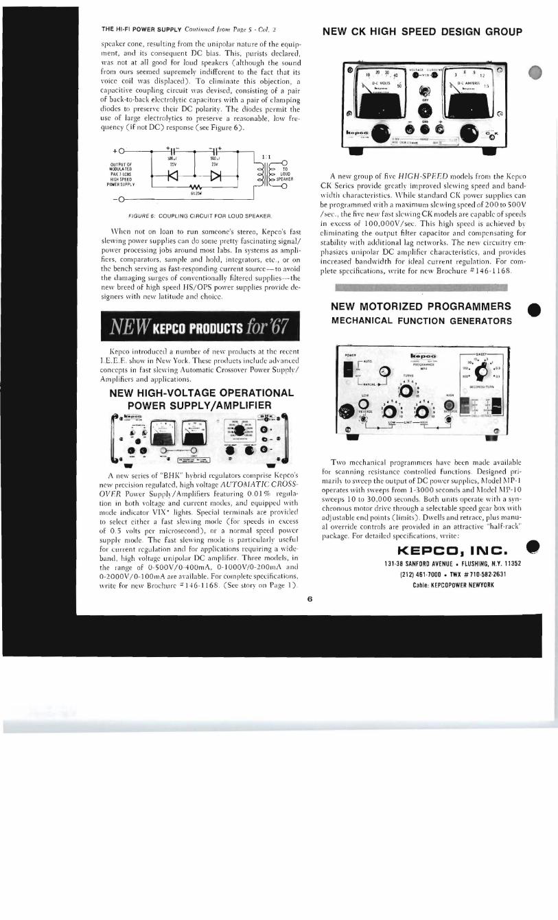
speaker cone , resu lt ing from the unipola r nature of th e equipmen t, an d it s conseqllen t D C bias . Thi s, purists declared, lI'as not at ~ II good for loud speakers (a lthough the sound fr om ours seemed suprem ek ind ifferent to th e fact that its I'o ice coil was displaced). To eliminate thi s obj ec tion, a ca pacitive coupling c ircuit was devised, consisting of ~ pair of back-ta-back electrolyti c capacitors with a pair of cl~mping diodes to preserve their DC polaritl' . The diodes permit the use of large elec tro lyti cs to preserve a reasonable, low frequency (iF not DC) response (see Figure 6).
OUTPUT Of MOOULA TEO PAX }- ICHS HIGH SPEED
POif£R SUPPL V
602!}(t
FIGURE 6: COUPLING CIRCUIT FOR LOUD SPEAKER.
\ Vhen not on loan to run someone's stereo, Kepco's fast slewing power supplies ca n cl o some prett)' fasci nat ing sign al! power processing jobs around most labs. In s),stems as amplifiers, compara tors , sam ple and hold, integrators, e tc., or on the bench servi ng as Fast-responding current source-to avoid the dam~ging surges of cOIlI'enti onall y filtered supplies- the nell' breed of high speed HS/OPS pOll'er supplies provide designers with nell' la titude a nd ch oice.
NEW KEPCO PRODUCTS for '(j7 Kepco introd uced a number of nell' prot/u cts at the rece nt
I.E .E.F. sholl' in Nell' York. These products include alhanced con cepts in Fast sle ll'in g t\u tom atic Crossol'er POlI'er Supph) Amplifiers and applications.
NEW HIGH-VOLTAGE OPERATIONAL POWER SUPPLY/AMPLIFIER
[~!i~ ~- . . [il' .~~"K.-": ~]I ,;--, . ' • • " I "- - ~ ft6J/rt -- - . ~ ~.
<l ~ . ~ - . - 0 - ~
!4! 2-"~' .. e G II ~ 1_::;::::.: -'"",.1 l' .. - ..
A nell' series of "B HK" hybrid regulators comprise Kepco's new precision regulatcd, high voltage AUTOMATIC CROSSOVER POlI'er Supply/Amplifiers featuring 0 .0 1 % reg lll~tion in both voltage and current modes, a nd eq uipped with mode indicator VIX' lights. Special te rmin als are prol'ided to select ei th er a fast slewing morle (for speeds in excess of 0 .5 volts per microsecond), or a normal speed pOll'er suppll' mocle. The Fast slewin g mode is part icular/v useful for current rcgu lati on and for ~pplicMions requiring a wideband . high I'ol tage un ipolar DC amplifier. Three models. in the range of 0 -sOOV/0 -400mf\, 0-1000V/0- 2001ll/\ a nd 0-200 0V/0- 1OOmA are available. For complete specifica tion s, write for nell' Brochure 'f H 6-116 8. ( See stor l' 011 Page I ).
6
NEW CK HIGH SPEED DESIGN GROUP
-)." o
h o pe.. • .. i G • c;'''' _.. .Ml' __ ___ . "" ,"""" I h " o;! II.~ -
A new group of five HIGH-SPE ED models from the Kepco CK Series provide grea tly improvecl slewing speed and bandwidth characteristics. While standard C I( power supplies can be program meclwith a maximum slell'ingspeed of200 to sOOV /sec., the five nell' fast skwing CI< models are capable of speecl s in excess of I OO ,OOO V/sec. Thi s high speed is achie ved bl' eliminating the ou tput filter capac itor and compen sa ting for s ta bility with add ition al lag networks. The new circuitry emphasizes unipolar DC amplifier characteris tics, and provides in creased bandwidth for ideal current regul atio n. For complete speCi ficati ons, write For new Brochure # 146-116 8,
NEW MOTORIZED PROGRAIVIMERS • MECHANICAL FUNCTION GENERATORS
~-~~~.!: ,._~iIt......t. ".'c'· .' .''100 . . O l
100 - · 0 1
Q -. Two mechan ica l programm ers hal'e been made ava ilable
for scanning res istance controlled functi ons. DeSigned primariJr to sweep the ou tput of DC power supplies, j\ lode} i\ IP-1 opera tes with sweeps from 1-3000 seconds and i\ Iodd i\ IP-l 0 sweeps 10 to 30,000 secon ds. Both u n its opera te with a synchronous motor dril'e throu gh a selec table speed gear box with ad justable e nd point s ( limits). Dwells and retrace, plu s manual o l'erride controls are provided in an a ttrac ti ve "h a lf-rack" package. For detailed speCi fi cations, write:
KEPCO. INC. 131 -38 SANFORD AVENUE. FLUSHING, N.Y. 11352
(212) 461·7000 • TWX #710-582-2631
Cable: KEPCOPOWER NEWYORK
•