key design engineering test pressure psi test liquid ... l stresses at nozzle openings have been...
TRANSCRIPT
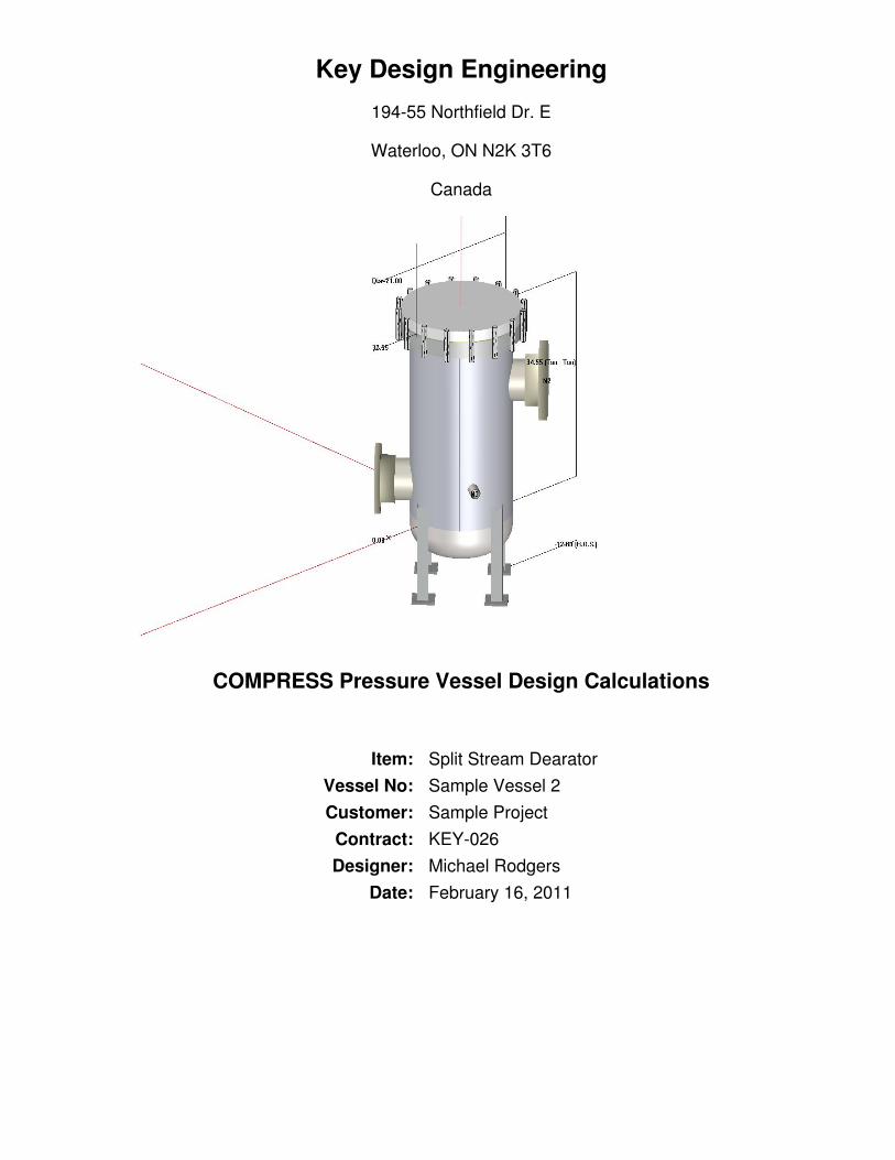
Key Design Engineering
194-55 Northfield Dr. E
Waterloo, ON N2K 3T6
Canada
COMPRESS Pressure Vessel Design Calculations
Item: Split Stream DearatorVessel No: Sample Vessel 2Customer: Sample Project
Contract: KEY-026Designer: Michael Rodgers
Date: February 16, 2011

Hydrostatic Test
Shop test pressure determination for Chamber bounded by F&D Head #1 and Bolted Cover #1 based onMAWP per UG-99(b)
Shop hydrostatic test gauge pressure is 195 psi at 70 °F (the chamber MAWP = 150 psi)
The shop test is performed with the vessel in the horizontal position.
IdentifierLocal testpressure
psi
Test liquidstatic head
psi
UG-99stressratio
UG-99pressure
factor
Stressduring test
psi
Allowabletest stress
psi
Stressexcessive?
Cylinder #1 195.778 0.778 1.0256 1.30 9,299 27,000 No
Straight Flange on F&D Head #1 195.781 0.781 1.0256 1.30 13,998 27,000 No
F&D Head #1 195.781 0.781 1.0256 1.30 14,096 27,000 No
Bolted Cover #1 195.778 0.778 1.0256 1.30 11,104 40,500 No
Flange #1 195.785 0.785 1.0256 1.30 16,982 40,500 No
Copy of Nozzle #1 (N2) (1) 195.921 0.921 1 1.30 21,170 40,500 No
Nozzle #1 (N1) 195.308 0.308 1.0256 1.30 21,103 40,500 No
Nozzle #3 (N3) 195.318 0.318 1 1.30 9,180 40,500 No
Notes:(1) Copy of Nozzle #1 (N2) limits the UG-99 stress ratio.(2) PL stresses at nozzle openings have been estimated using the method described in PVP-Vol. 399, pages 77-82.(3) 1.5*0.9*Sy used as the basis for the maximum local primary membrane stress at the nozzle intersection PL.(4) The zero degree angular position is assumed to be up, and the test liquid height is assumed to the top-mostflange.
The field test condition has not been investigated for the Chamber bounded by F&D Head #1 and Bolted Cover #1.
The test temperature of 70 °F is warmer than the minimum recommended temperature of -25 °F so the brittle fractureprovision of UG-99(h) has been met.
1/78
Table Of ContentsHydrostatic Test1.
Deficiencies Summary2.
Long Seam Summary3.
Settings Summary4.
Pressure Summary5.
Nozzle Summary6.
Nozzle Schedule7.
Thickness Summary8.
F&D Head #19.
Bolted Cover #110.
Cylinder #111.
Legs #112.
Flange #113.
Nozzle #1 (N1)14.
Copy of Nozzle #1 (N2)15.
Nozzle #3 (N3)16.
Straight Flange on F&D Head #117.
Weight Summary18.
2/78

Deficiencies Summary
No deficiencies found.
3/78

Long Seam Summary
Shell Long SeamAngles
Component Seam 1
Cylinder #1 315°
Shell Plate Lengths
Component StartingAngle Plate 1
Cylinder #1 315° 55.9596"
*North is located at 0°*Plate Lengths use the circumfrence of the vessel based on the mid diameter of the components
4/78

Shell Rollout
5/78

Settings Summary
COMPRESS Build 7110
Units: U.S. Customary
Datum Line Location: 0.00" from bottom seam
Design
ASME Section VIII Division 1, 2010 Edition
Design or Rating: Get Thickness from PressureMinimum thickness: 0.0625" per UG-16(b)Design for cold shut down only: NoDesign for lethal service (full radiography required): NoDesign nozzles for: Design P, find nozzle MAWP and MAPCorrosion weight loss: 100% of theoretical lossUG-23 Stress Increase: 1.20Skirt/legs stress increase: 1.0Minimum nozzle projection: 0.01"Juncture calculations for α > 30 only: YesPreheat P-No 1 Materials > 1.25" and <= 1.50" thick: NoUG-37(a) shell tr calculation considers longitudinal stress: NoButt welds are tapered per Figure UCS-66.3(a).
Hydro/Pneumatic Test
Shop Hydrotest Pressure: 1.3 times vesselMAWP
Test liquid specific gravity: 1.00Maximum stress during test: 90% of yield
Required Marking - UG-116
UG-116(e) Radiography: RT4UG-116(f) Postweld heat treatment: None
Code Cases\Interpretations
Use Code Case 2547: NoApply interpretation VIII-1-83-66: NoApply interpretation VIII-1-86-175: YesApply interpretation VIII-1-83-115: NoApply interpretation VIII-1-01-37: YesNo UCS-66.1 MDMT reduction: NoNo UCS-68(c) MDMT reduction: NoDisallow UG-20(f) exemptions: No
6/78

UG-22 Loadings
UG-22(a) Internal or External Design Pressure : YesUG-22(b) Weight of the vessel and normal contents under operating or test conditions: YesUG-22(c) Superimposed static reactions from weight of attached equipment (external loads): NoUG-22(d)(2) Vessel supports such as lugs, rings, skirts, saddles and legs: YesUG-22(f) Wind reactions: NoUG-22(f) Seismic reactions: NoUG-22(j) Test pressure and coincident static head acting during the test: YesNote: UG-22(b),(c) and (f) loads only considered when supports are present.
7/78

Pressure Summary
Pressure Summary for Chamber bounded by F&D Head #1 and Bolted Cover #1
IdentifierP
Design( psi)
T
Design( °F)
MAWP( psi)
MAP( psi)
MAEP( psi)
Te
external( °F)
MDMT( °F)
MDMTExemption
ImpactTested
Bolted Cover #1 150 250 343.82 352.63 497.66 250 -320 Note 1 No
Cylinder #1 150 250 266.28 273.11 93.73 250 -320 Note 1 No
Straight Flange on F&D Head #1 150 250 231.49 237.43 46.41 250 -320 Note 1 No
F&D Head #1 150 250 177.2 181.75 50.44 250 -320 Note 2 No
Legs #1 150 250 150 N/A N/A N/A N/A N/A N/A
Flange #1 150 250 163.54 169.84 488.49 250 -55 Note 3 No
Nozzle #1 (N1) 150 250 245 257.44 68.55 250 -55 Note 4 No
Copy of Nozzle #1 (N2) 150 250 242.26 246.89 66.07 250 -55 Note 5 No
Nozzle #3 (N3) 150 250 409.67 420.17 93.73 250 -55 Note 5 No
Chamber design MDMT is -20 °FChamber rated MDMT is -55 °F @ 150 psiChamber MAWP was used in the MDMT determination
Chamber MAWP hot & corroded is 150 psi @ 250 °F
Chamber MAP cold & new is 169.84 psi @ 70 °F
Chamber MAEP is 46.41 psi @ 250 °FVacuum rings did not govern the external pressure rating.
Notes for MDMT Rating:
Note # Exemption Details
1. Rated MDMT per UHA-51(d)(1)(a) = -320 °F
2. Material Rated MDMT per UHA-51(d)(1)(a) = -320 °F
3. Flange Rated MDMT per UHA-51(d)(1)(a) = -320 °F Bolts rated MDMT per Fig UCS-66 note (c) = -55 °F
4. Flange rating governs: UCS-66(b)(1)(b)
5.Nozzle impact test exemption temperature from Fig UCS-66 Curve B = -20 °FFig UCS-66.1 MDMT reduction = 130.8 °F, (coincident ratio = 0.35893)Rated MDMT is governed by UCS-66(b)(2)
UCS-66 governing thickness = 0.1875 in.
Design notes are available on the Settings Summary page.
8/78

Nozzle Summary
Nozzlemark
OD(in)
tn
(in)Req t
n(in)
A1? A2?Shell Reinforcement
Pad Corr(in)
Aa/A
r(%)
Nom t(in)
Design t(in)
User t(in)
Width(in)
tpad(in)
N1 6.625 0.28 0.1318 Yes Yes 0.1875 0.1528 N/A N/A 0 100.0
N2 6.625 0.28 0.1272 Yes Yes 0.1875 0.1113 N/A N/A 0 100.0
N3 1.75 0.2175 0.0625 Yes Yes 0.1875 N/A N/A N/A 0 Exempt
tn: Nozzle thicknessReq tn: Nozzle thickness required per UG-45/UG-16Nom t: Vessel wall thicknessDesign t: Required vessel wall thickness due to pressure + corrosion allowance per UG-37User t: Local vessel wall thickness (near opening)Aa: Area available per UG-37, governing conditionAr: Area required per UG-37, governing conditionCorr: Corrosion allowance on nozzle wall
9/78

Nozzle Schedule
Nozzlemark
Service SizeMaterials
Nozzle Impact Norm FineGrain Pad Impact Norm Fine
Grain Flange
N1 Nozzle #1 NPS 6 Sch 40S (Std) SA-312 TP304 Wld &smls pipe No No No N/A N/A N/A N/A
WN A105Class150
N2 Copy of Nozzle#1 NPS 6 Sch 40 (Std) SA-106 B Smls pipe No No No N/A N/A N/A N/A
WN A105Class300
N3 Nozzle #3 NPS 1 Class 3000 -threaded SA-105 No No No N/A N/A N/A N/A N/A
10/78

Thickness Summary
ComponentIdentifier
Material Diameter(in)
Length(in)
Nominal t(in)
Design t(in)
Total Corrosion(in)
JointE
Load
Bolted Cover #1 SA-240 304 21 OD 1.75 1.75* 1.1559 0 1.00 Internal
Cylinder #1 SA-240 304 18 OD 32 0.1875 0.1061 0 0.65 Internal
Straight Flange on F&D Head #1 SA-240 304 18 OD 2 0.125 0.0812 0 0.85 Internal
F&D Head #1 SA-240 304 18 OD 4.8285 0.125* 0.106 0 0.85 Internal
Nominal t: Vessel wall nominal thickness
Design t: Required vessel thickness due to governing loading + corrosion
Joint E: Longitudinal seam joint efficiency
* Head minimum thickness after forming
Load
internal: Circumferential stress due to internal pressure governs
external: External pressure governs
Wind: Combined longitudinal stress of pressure + weight + wind governs
Seismic: Combined longitudinal stress of pressure + weight + seismic governs
11/78

F&D Head #1
ASME Section VIII, Division 1, 2010 Edition
Component: F&D HeadMaterial Specification: SA-240 304 (II-D p.86, ln. 25)Material Rated MDMT per UHA-51(d)(1)(a) = -320 °F
Internal design pressure: P = 150 psi @ 250 °FExternal design pressure: Pe = 15 psi @ 250 °F
Static liquid head:
Ps= 0 psi (SG=1, Hs=0" Operating head)Pth= 0.7806 psi (SG=1, Hs=21.6259" Horizontal test head)
Corrosion allowance: Inner C = 0" Outer C = 0"
Design MDMT = -20°F No impact test performedRated MDMT = -320°F Material is not normalized
Material is not produced to fine grain practicePWHT is not performedDo not Optimize MDMT / Find MAWP
Radiography: Category A joints - Spot UW-11(b) Type 1 Head to shell seam - UserDefined (E = 0.5)
Estimated weight*: new = 17.5 lb corr = 17.5 lbCapacity*: new = 5.7 US gal corr = 5.7 US gal* includes straight flange
Outer diameter = 18"Crown radius L = 18"Knuckle radius r = 3.75"Minimum head thickness = 0.125"Straight flange length Lsf = 2"Nominal straight flange thickness tsf = 0.125"Results Summary
The governing condition is internal pressure.Minimum thickness per UG-16 = 0.0625" + 0" = 0.0625"Design thickness due to internal pressure (t) = 0.106"Design thickness due to external pressure (te) = 0.0543"Maximum allowable working pressure (MAWP) = 177.2 psiMaximum allowable pressure (MAP) = 181.75 psiMaximum allowable external pressure (MAEP) = 50.44 psi
Note: Appendix 1-4 footnote 1 used to determine allowable stress.
M (Corroded)
M=1/4*[3 + (L / r)1/2]=1/4*[3 + (18 / 3.75)1/2]=1.297723
12/78
M (New)
M=1/4*[3 + (L / r)1/2]=1/4*[3 + (18 / 3.75)1/2]=1.297723
Design thickness for internal pressure, (Corroded at 250 °F) Appendix 1-4(d)
t = P*Lo*M / (2*S*E + P*(M - 0.2)) + Corrosion= 150*18.125*1.2977 / (2*19,500*0.85 + 150*(1.2977 - 0.2)) + 0= 0.1059"
The head internal pressure design thickness is 0.106".
Maximum allowable working pressure, (Corroded at 250 °F) Appendix 1-4(d)
P = 2*S*E*t / (M*Lo - t*(M - 0.2)) - Ps= 2*19,500*0.85*0.125 / (1.2977*18.125 - 0.125*(1.2977 - 0.2)) - 0= 177.2 psi
The maximum allowable working pressure (MAWP) is 177.2 psi.
Maximum allowable pressure, (New at 70 °F) Appendix 1-4(d)
P = 2*S*E*t / (M*Lo - t*(M - 0.2)) - Ps= 2*20,000*0.85*0.125 / (1.2977*18.125 - 0.125*(1.2977 - 0.2)) - 0= 181.75 psi
The maximum allowable pressure (MAP) is 181.75 psi.
Design thickness for external pressure, (Corroded at 250 °F) UG-33(e)
Equivalent outside spherical radius (Ro)= Outside crown radius= 18.125 in
A = 0.125 / (Ro / t)= 0.125 / (18.125 / 0.054243)= 0.000374
From TableHA-1: B = 5,012.2065
psi
Pa = B / (Ro / t)= 5,012.207 / (18.125 / 0.0542)= 15 psi
t = 0.0542" + Corrosion = 0.0542" + 0" = 0.0542"Check the external pressure per UG-33(a)(1) Appendix 1-4(d)
t = 1.67*Pe*Lo*M / (2*S*E + 1.67*Pe*(M - 0.2)) + Corrosion= 1.67*15*18.125*1.2977 / (2*19,500*1 + 1.67*15*(1.2977 - 0.2)) + 0= 0.0151"
The head external pressure design thickness (te) is 0.0542".
Maximum Allowable External Pressure, (Corroded at 250 °F) UG-33(e)
Equivalent outside spherical radius (Ro)
13/78

= Outside crown radius= 18.125 in
A = 0.125 / (Ro / t)= 0.125 / (18.125 / 0.125)= 0.000862
From TableHA-1: B = 7,313.6406
psi
Pa = B / (Ro / t)= 7,313.641 / (18.125 / 0.125)= 50.4389 psi
Check the Maximum External Pressure, UG-33(a)(1) Appendix 1-4(d)
P = 2*S*E*t / ((M*Lo - t*(M - 0.2))*1.67) - Ps2= 2*19,500*1*0.125 / ((1.2977*18.125 - 0.125*(1.2977 - 0.2))*1.67) - 0= 124.84 psi
The maximum allowable external pressure (MAEP) is 50.44 psi.
% Forming strain - UHA-44(a)(2)(b)
EFE = (75*t / Rf)*(1 - Rf / Ro)= (75*0.125 / 3.8125)*(1 - 3.8125 / ∞)= 2.459%
14/78
Bolted Cover #1
ASME Section VIII Division 1, 2010 Edition
Component: Bolted CoverAttached to: Flange #1Material specification: SA-240 304 (II-D p. 86, ln. 25)Rated MDMT per UHA-51(d)(1)(a) = -320 °F
Internal design pressure: P = 150 psi @ 250 °FExternal design pressure: Pe = 15 psi @ 250 °F
Static liquid head:
Pth = 0.79 psi (SG = 1, Hs = 21.7509", Horizontal testhead)
Corrosion allowance: Inner C = 0" Outer C = 0"
Design MDMT = -20 °F No impact test performedRated MDMT = -320 °F Material is not normalized
Material is not produced to Fine Grain PracticePWHT is not performed
Radiography: Category A joints - Seamless No RT
Estimated weight: New = 175.8 lb corr = 175.8 lb
Head diameter, d = 20"Cover thickness, t = 1.75"Design thickness, (at 250 °F) UG-34 (c)(2), flange operating
t = d*Sqr(C*P / (S*E) + 1.9*W*hG / (S*E*d3)) + Corrosion= 20*Sqr(0.3*150 / (19,500*1) + 1.9*56,520*1.5 / (19,500*1*203)) + 0= 1.1559 in
Design thickness, (at 70 °F) UG-34 (c)(2), gasket seating
t = d*Sqr(1.9*W*hG / (S*E*d3)) + Corrosion= 20*Sqr(1.9*68,660*1.5 / (20,000*1*203)) + 0= 0.6994 in
Maximum allowable working pressure, (at 250 °F )
P = (S*E / C)*((t / d)2 - (1.9*W*hG / (S*E*d3))) - Ps= (19,500*1 / 0.3)*((1.75 / 20)2 - (1.9*129,550*1.5 / (19,500*1*203))) - 0= 343.82 psi
Maximum allowable pressure, (At 70 °F )
P = (S*E / C)*((t / d)2 - (1.9*W*hG / (S*E*d3)))= (20,000*1 / 0.3)*((1.75 / 20)2 - (1.9*132,871.7*1.5 / (20,000*1*203)))= 352.63 psi
Design thickness for external pressure, (at 250 °F) U-2(g)
t = d*Sqr(C*Pa / (S*E)) + Corrosion
15/78

= 20*Sqr(0.3*15 / (19,500*1)) + 0= 0.3038 in
Maximum allowable external pressure, (At 250 °F ) U-2(g)
Pa = (S*E / C)*(t / d)2
= (19,500*1 / 0.3)*(1.75 / 20)2
= 497.66 psi
16/78

Cylinder #1
ASME Section VIII Division 1, 2010 Edition
Component: CylinderMaterial specification: SA-240 304 (II-D p. 86, ln. 25)Rated MDMT per UHA-51(d)(1)(a) = -320 °F
Internal design pressure: P = 150 psi @ 250 °FExternal design pressure: Pe = 15 psi @ 250 °F
Static liquid head:
Pth = 0.78 psi (SG = 1, Hs = 21.5634", Horizontal testhead)
Corrosion allowance Inner C = 0" Outer C = 0"
Design MDMT = -20 °F No impact test performedRated MDMT = -320 °F Material is not normalized
Material is not produced to Fine Grain PracticePWHT is not performed
Radiography: Longitudinal joint - None UW-11(c) Type 2Top circumferential joint - N/ABottom circumferential joint - UserDefined
E = 0.5
Estimated weight New = 93.5 lb corr = 93.5 lbCapacity New = 33.8 US gal corr = 33.8 US gal
OD = 18"LengthLc
= 32"
t = 0.1875"
Design thickness, (at 250 °F) Appendix 1-1
t = P*Ro / (S*E + 0.40*P) + Corrosion= 150*9 / (19,500*0.65 + 0.40*150) + 0= 0.1061"
Maximum allowable working pressure, (at 250 °F) Appendix 1-1
P = S*E*t / (Ro - 0.40*t) - Ps= 19,500*0.65*0.1875 / (9 - 0.40*0.1875) - 0= 266.28 psi
Maximum allowable pressure, (at 70 °F) Appendix 1-1
P = S*E*t / (Ro - 0.40*t)= 20,000*0.65*0.1875 / (9 - 0.40*0.1875)= 273.11 psi
17/78
External Pressure, (Corroded & at 250 °F) UG-28(c)
L /Do
= 36.1178/ 18 = 2.0065
Do/ t = 18 /
0.0791 = 227.4320
From table G: A = 0.000191From tableHA-1: B = 2,558.6055
psi
Pa = 4*B / (3*(Do / t))
= 4*2,558.61 / (3*(18 /0.0791))
= 15 psi
Design thickness for external pressure Pa = 15 psi
ta = t +Corrosion = 0.0791
+ 0 = 0.0791"
Maximum Allowable External Pressure, (Corroded & at 250 °F) UG-28(c)
L /Do
= 36.1178/ 18 = 2.0065
Do/ t = 18 /
0.1875 = 96.0000
From table G: A = 0.000689From tableHA-1: B = 6,748.7842
psi
Pa = 4*B / (3*(Do / t))
= 4*6,748.78 / (3*(18 /0.1875))
= 93.73 psi
% Forming strain - UHA-44(a)(2)(a)
EFE = (50*t / Rf)*(1 - Rf / Ro)= (50*0.1875 / 8.9063)*(1 - 8.9063 / ∞)= 1.0526%
External Pressure + Weight Check (Bergman, ASME paper 54-A-104)
Pv = W / (2*π*Rm) + M / (π*Rm2)
= 412.8 / (2*π*8.9063) + 261 / (π*8.90632)= 8.4235 lb/in
α = Pv / (Pe*Do)= 8.4235 / (15*18)= 0.0312
n = 4
m = 1.23 / (L / Do)2
= 1.23 / (36.1178 / 18)2
= 0.3055
18/78

Ratio Pe = (n2 - 1 + m + m*α) / (n2 - 1 + m)= (42 - 1 + 0.3055 + 0.3055*0.0312) / (42 - 1 + 0.3055)= 1.0006
Ratio Pe * Pe ≤ MAEP design cylinder thickness is satisfactory.
External Pressure + Weight Check at Bottom Seam (Bergman, ASME paper 54-A-104)
Pv = W / (2*π*Rm) + M / (π*Rm2)
= -20.5 / (2*π*8.9063) + 0 / (π*8.90632)= -0.3669 lb/in
α = Pv / (Pe*Do)= -0.3669 / (15*18)= -0.0014
n = 4
m = 1.23 / (L / Do)2
= 1.23 / (36.1178 / 18)2
= 0.3055
Ratio Pe = (n2 - 1 + m + m*α) / (n2 - 1 + m)= (42 - 1 + 0.3055 + 0.3055*-0.0014) / (42 - 1 + 0.3055)= 1.0000
Ratio Pe * Pe ≤ MAEP design cylinder thickness is satisfactory.
Design thickness = 0.1061"
The governing condition is due to internal pressure.
The cylinder thickness of 0.1875" is adequate.
Thickness Required Due to Pressure + External Loads
Condition Pressure P (psi)
Allowable StressBefore UG-23
Stress Increase (psi)
Temperature (°F)
Corrosion C(in) Location Load Req'd Thk Due to
Tension (in)
Req'd Thk Dueto
Compression(in)
St Sc
Operating, Hot & Corroded 150 19,500 10,322 250 0 Top Weight 0.0335 0.0334
Bottom Weight 0.0339 0.0339
Operating, Hot & New 150 19,500 10,322 250 0 Top Weight 0.0335 0.0334
Bottom Weight 0.0339 0.0339
Hot Shut Down, Corroded 0 19,500 10,322 250 0 Top Weight 0.0006 0.0008
Bottom Weight 0 0
Hot Shut Down, New 0 19,500 10,322 250 0 Top Weight 0.0006 0.0008
Bottom Weight 0 0
Empty, Corroded 0 20,000 12,142 70 0 Top Weight 0.0005 0.0007
Bottom Weight 0 0
Empty, New 0 20,000 12,142 70 0 Top Weight 0.0005 0.0007
Bottom Weight 0 0
Vacuum -15 19,500 10,322 250 0 Top Weight 0.007 0.0072
19/78

Bottom Weight 0.0064 0.0064
Hot Shut Down, Corroded,Weight & Eccentric MomentsOnly 0 19,500 10,322 250 0
Top Weight 0.0006 0.0008
Bottom Weight 0 0
Allowable Compressive Stress, Hot and Corroded- ScHC, (table HA-1)A = 0.125 / (Ro / t)
= 0.125 / (9 / 0.1875)= 0.002604
B = 10,322 psi
S = 19,500 / 1.00 = 19,500 psi
ScHC = min(B, S) = 10,322 psi
Allowable Compressive Stress, Hot and New- ScHN
ScHN = ScHC
= 10,322 psi
Allowable Compressive Stress, Cold and New- ScCN, (table HA-1)A = 0.125 / (Ro / t)
= 0.125 / (9 / 0.1875)= 0.002604
B = 12,142 psi
S = 20,000 / 1.00 = 20,000 psi
ScCN = min(B, S) = 12,142 psi
Allowable Compressive Stress, Cold and Corroded- ScCC
ScCC = ScCN
= 12,142 psi
Allowable Compressive Stress, Vacuum and Corroded- ScVC, (table HA-1)A = 0.125 / (Ro / t)
= 0.125 / (9 / 0.1875)= 0.002604
B = 10,322 psi
S = 19,500 / 1.00 = 19,500 psi
ScVC = min(B, S) = 10,322 psi
Operating, Hot & Corroded, Above Support Point
tp = P*R / (2*St*Ks*Ec + 0.40*|P|) (Pressure)= 150*8.8125 / (2*19,500*1.00*1.00 + 0.40*|150|)= 0.0338"
tm = M / (π*Rm2*St*Ks*Ec) (bending)
= 261 / (π*8.90632*19,500*1.00*1.00)= 0.0001"
20/78

tw = W / (2*π*Rm*St*Ks*Ec) (Weight)= 412.8 / (2*π*8.9063*19,500*1.00*1.00)= 0.0004"
tt = tp + tm - tw(total required,tensile)
= 0.0338 + 0.0001 - (0.0004)= 0.0335"
tc = |tmc + twc - tpc|(total, nettensile)
= |0.0001 + (0.0004) - (0.0338)|= 0.0334"
Maximum allowable working pressure, Longitudinal Stress
P = 2*St*Ks*Ec*(t - tm + tw) / (R - 0.40*(t - tm + tw))= 2*19,500*1.00*1.00*(0.1875 - 0.0001 + (0.0004)) / (8.8125 - 0.40*(0.1875 - 0.0001 + (0.0004)))= 838.37 psi
Operating, Hot & New, Above Support Point
tp = P*R / (2*St*Ks*Ec + 0.40*|P|) (Pressure)= 150*8.8125 / (2*19,500*1.00*1.00 + 0.40*|150|)= 0.0338"
tm = M / (π*Rm2*St*Ks*Ec) (bending)
= 261 / (π*8.90632*19,500*1.00*1.00)= 0.0001"
tw = W / (2*π*Rm*St*Ks*Ec) (Weight)= 412.8 / (2*π*8.9063*19,500*1.00*1.00)= 0.0004"
tt = tp + tm - tw(total required,tensile)
= 0.0338 + 0.0001 - (0.0004)= 0.0335"
tc = |tmc + twc - tpc|(total, nettensile)
= |0.0001 + (0.0004) - (0.0338)|= 0.0334"
Maximum allowable working pressure, Longitudinal Stress
P = 2*St*Ks*Ec*(t - tm + tw) / (R - 0.40*(t - tm + tw))= 2*19,500*1.00*1.00*(0.1875 - 0.0001 + (0.0004)) / (8.8125 - 0.40*(0.1875 - 0.0001 + (0.0004)))= 838.37 psi
Hot Shut Down, Corroded, Above Support Point
tp = 0" (Pressure)tm = M / (π*Rm
2*Sc*Ks) (bending)
21/78

= 261 / (π*8.90632*10,322.04*1.00)= 0.0001"
tw = W / (2*π*Rm*Sc*Ks) (Weight)= 412.8 / (2*π*8.9063*10,322.04*1.00)= 0.0007"
tt = |tp + tm - tw| (total, net compressive)= |0 + 0.0001 - (0.0007)|= 0.0006"
tc = tmc + twc - tpc (total required, compressive)= 0.0001 + (0.0007) - (0)= 0.0008"
Hot Shut Down, New, Above Support Point
tp = 0" (Pressure)tm = M / (π*Rm
2*Sc*Ks) (bending)= 261 / (π*8.90632*10,322.04*1.00)= 0.0001"
tw = W / (2*π*Rm*Sc*Ks) (Weight)= 412.8 / (2*π*8.9063*10,322.04*1.00)= 0.0007"
tt = |tp + tm - tw| (total, net compressive)= |0 + 0.0001 - (0.0007)|= 0.0006"
tc = tmc + twc - tpc (total required, compressive)= 0.0001 + (0.0007) - (0)= 0.0008"
Empty, Corroded, Above Support Point
tp = 0" (Pressure)tm = M / (π*Rm
2*Sc*Ks) (bending)= 261 / (π*8.90632*12,141.51*1.00)= 0.0001"
tw = W / (2*π*Rm*Sc*Ks) (Weight)= 412.8 / (2*π*8.9063*12,141.51*1.00)= 0.0006"
tt = |tp + tm - tw| (total, net compressive)= |0 + 0.0001 - (0.0006)|= 0.0005"
tc = tmc + twc - tpc (total required, compressive)= 0.0001 + (0.0006) - (0)= 0.0007"
22/78

Empty, New, Above Support Point
tp = 0" (Pressure)tm = M / (π*Rm
2*Sc*Ks) (bending)= 261 / (π*8.90632*12,141.51*1.00)= 0.0001"
tw = W / (2*π*Rm*Sc*Ks) (Weight)= 412.8 / (2*π*8.9063*12,141.51*1.00)= 0.0006"
tt = |tp + tm - tw| (total, net compressive)= |0 + 0.0001 - (0.0006)|= 0.0005"
tc = tmc + twc - tpc (total required, compressive)= 0.0001 + (0.0006) - (0)= 0.0007"
Vacuum, Above Support Point
tp = P*R / (2*Sc*Ks + 0.40*|P|) (Pressure)= -15*8.8125 / (2*10,322.04*1.00 + 0.40*|15|)= -0.0064"
tm = M / (π*Rm2*Sc*Ks) (bending)
= 261 / (π*8.90632*10,322.04*1.00)= 0.0001"
tw = W / (2*π*Rm*Sc*Ks) (Weight)= 412.8 / (2*π*8.9063*10,322.04*1.00)= 0.0007"
tt = |tp + tm - tw| (total, net compressive)= |-0.0064 + 0.0001 - (0.0007)|= 0.007"
tc = tmc + twc - tpc (total required, compressive)= 0.0001 + (0.0007) - (-0.0064)= 0.0072"
Maximum Allowable External Pressure, Longitudinal Stress
P = 2*Sc*Ks*(t - tmc - twc) / (R - 0.40*(t - tmc - twc))= 2*10,322.04*1.00*(0.1875 - 0.0001 - 0.0007) / (8.8125 - 0.40*(0.1875 - 0.0001 - 0.0007))= 441.06 psi
Hot Shut Down, Corroded, Weight & Eccentric Moments Only, Above Support Point
tp = 0" (Pressure)tm = M / (π*Rm
2*Sc*Ks) (bending)= 261 / (π*8.90632*10,322.04*1.00)= 0.0001"
23/78

tw = W / (2*π*Rm*Sc*Ks) (Weight)= 412.8 / (2*π*8.9063*10,322.04*1.00)= 0.0007"
tt = |tp + tm - tw| (total, net compressive)= |0 + 0.0001 - (0.0007)|= 0.0006"
tc = tmc + twc - tpc (total required, compressive)= 0.0001 + (0.0007) - (0)= 0.0008"
Operating, Hot & Corroded, Below Support Point
tp = P*R / (2*St*Ks*Ec + 0.40*|P|) (Pressure)= 150*8.8125 / (2*19,500*1.00*1.00 + 0.40*|150|)= 0.0338"
tm = M / (π*Rm2*St*Ks*Ec) (bending)
= 0 / (π*8.90632*19,500*1.00*1.00)= 0"
tw = W / (2*π*Rm*St*Ks*Ec) (Weight)= -20.5 / (2*π*8.9063*19,500*1.00*1.00)= 0"
tt = tp + tm - tw(total required,tensile)
= 0.0338 + 0 - (0)= 0.0339"
tc = |tmc + twc - tpc|(total, nettensile)
= |0 + (0) - (0.0338)|= 0.0339"
Maximum allowable working pressure, Longitudinal Stress
P = 2*St*Ks*Ec*(t - tm + tw) / (R - 0.40*(t - tm + tw))= 2*19,500*1.00*1.00*(0.1875 - 0 + (0)) / (8.8125 - 0.40*(0.1875 - 0 + (0)))= 836.83 psi
Operating, Hot & New, Below Support Point
tp = P*R / (2*St*Ks*Ec + 0.40*|P|) (Pressure)= 150*8.8125 / (2*19,500*1.00*1.00 + 0.40*|150|)= 0.0338"
tm = M / (π*Rm2*St*Ks*Ec) (bending)
= 0 / (π*8.90632*19,500*1.00*1.00)= 0"
tw = W / (2*π*Rm*St*Ks*Ec) (Weight)= -20.5 / (2*π*8.9063*19,500*1.00*1.00)
24/78

= 0"
tt = tp + tm - tw(total required,tensile)
= 0.0338 + 0 - (0)= 0.0339"
tc = |tmc + twc - tpc|(total, nettensile)
= |0 + (0) - (0.0338)|= 0.0339"
Maximum allowable working pressure, Longitudinal Stress
P = 2*St*Ks*Ec*(t - tm + tw) / (R - 0.40*(t - tm + tw))= 2*19,500*1.00*1.00*(0.1875 - 0 + (0)) / (8.8125 - 0.40*(0.1875 - 0 + (0)))= 836.83 psi
Hot Shut Down, Corroded, Below Support Point
tp = 0" (Pressure)tm = M / (π*Rm
2*St*Ks*Ec) (bending)= 0 / (π*8.90632*19,500*1.00*1.00)= 0"
tw = W / (2*π*Rm*St*Ks*Ec) (Weight)= -20.5 / (2*π*8.9063*19,500*1.00*1.00)= 0"
tt = tp + tm - tw(total required,tensile)
= 0 + 0 - (0)= 0"
tc = |tmc + twc - tpc|(total, nettensile)
= |0 + (0) - (0)|= 0"
Hot Shut Down, New, Below Support Point
tp = 0" (Pressure)tm = M / (π*Rm
2*St*Ks*Ec) (bending)= 0 / (π*8.90632*19,500*1.00*1.00)= 0"
tw = W / (2*π*Rm*St*Ks*Ec) (Weight)= -20.5 / (2*π*8.9063*19,500*1.00*1.00)= 0"
tt = tp + tm - tw(total required,tensile)
= 0 + 0 - (0)= 0"
25/78

tc = |tmc + twc - tpc|(total, nettensile)
= |0 + (0) - (0)|= 0"
Empty, Corroded, Below Support Point
tp = 0" (Pressure)tm = M / (π*Rm
2*St*Ks*Ec) (bending)= 0 / (π*8.90632*20,000*1.00*1.00)= 0"
tw = W / (2*π*Rm*St*Ks*Ec) (Weight)= -20.5 / (2*π*8.9063*20,000*1.00*1.00)= 0"
tt = tp + tm - tw(total required,tensile)
= 0 + 0 - (0)= 0"
tc = |tmc + twc - tpc|(total, nettensile)
= |0 + (0) - (0)|= 0"
Empty, New, Below Support Point
tp = 0" (Pressure)tm = M / (π*Rm
2*St*Ks*Ec) (bending)= 0 / (π*8.90632*20,000*1.00*1.00)= 0"
tw = W / (2*π*Rm*St*Ks*Ec) (Weight)= -20.5 / (2*π*8.9063*20,000*1.00*1.00)= 0"
tt = tp + tm - tw(total required,tensile)
= 0 + 0 - (0)= 0"
tc = |tmc + twc - tpc|(total, nettensile)
= |0 + (0) - (0)|= 0"
Vacuum, Below Support Point
tp = P*R / (2*Sc*Ks + 0.40*|P|) (Pressure)= -15*8.8125 / (2*10,322.04*1.00 + 0.40*|15|)= -0.0064"
tm = M / (π*Rm2*Sc*Ks) (bending)
26/78

= 0 / (π*8.90632*10,322.04*1.00)= 0"
tw = W / (2*π*Rm*Sc*Ks) (Weight)= -20.5 / (2*π*8.9063*10,322.04*1.00)= 0"
tt = |tp + tm - tw| (total, net compressive)= |-0.0064 + 0 - (0)|= 0.0064"
tc = tmc + twc - tpc (total required, compressive)= 0 + (0) - (-0.0064)= 0.0064"
Maximum Allowable External Pressure, Longitudinal Stress
P = 2*Sc*Ks*(t - tmc - twc) / (R - 0.40*(t - tmc - twc))= 2*10,322.04*1.00*(0.1875 - 0 - 0) / (8.8125 - 0.40*(0.1875 - 0 - 0))= 443.09 psi
Hot Shut Down, Corroded, Weight & Eccentric Moments Only, Below Support Point
tp = 0" (Pressure)tm = M / (π*Rm
2*St*Ks*Ec) (bending)= 0 / (π*8.90632*19,500*1.00*1.00)= 0"
tw = W / (2*π*Rm*St*Ks*Ec) (Weight)= -20.5 / (2*π*8.9063*19,500*1.00*1.00)= 0"
tt = tp + tm - tw(total required,tensile)
= 0 + 0 - (0)= 0"
tc = |tmc + twc - tpc|(total, nettensile)
= |0 + (0) - (0)|= 0"
27/78

Legs #1
Leg material:
Leg description: 2x2x1/8 Equal Angle(Leg in)
Number of legs: N = 4Overall length: 16 inBase to girth seam length: 12.8 inBolt circle: 16 inAnchor bolt size: 0.375 inch series 8 threadedAnchor bolt material:Anchor bolts/leg: 1Anchor bolt allowable stress: Sb = 20,000 psiAnchor bolt corrosion allowance: 0 inAnchor bolt hole clearance: 0.375 inBase plate width: 4 inBase plate length: 4 inBase plate thickness: 0.375 in (0.0517 in required)Base plate allowable stress: 24,000 psiFoundation allowable bearing stress: 1,658 psiEffective length coefficient: K = 1.2Coefficient: Cm = 0.85Leg yield stress: Fy = 36,000 psiLeg elastic modulus: E = 29,000,000 psiLeg to shell fillet weld: 0.25 in (0.0014 in required)Legs braced: No
28/78

Note: The support attachment point is assumed to be 1 in up from the cylinder circumferential seam.
LoadingForceattack
angle °
Legposition °
Axialend load
lbf
Shearresisted
lbf
Axialfa
psi
Bendingfbxpsi
Bendingfbypsi
RatioH1-1
RatioH1-2
GoverningCondition
Weightoperatingcorroded
Moment =21.7 lbf-ft
0
0 97.7 0.0 202 526 0 0.0355 0.0370
90 112.2 0.0 232 604 0 0.0408 0.0425
180 126.7 0.0 262 682 0 0.0461 0.0480
270 112.2 0.0 232 604 0 0.0408 0.0425
LoadingForceattack
angle °
Legposition °
Axialend load
lbf
Shearresisted
lbf
Axialfa
psi
Bendingfbxpsi
Bendingfbypsi
RatioH1-1
RatioH1-2
Weightempty
corroded
Moment =21.7 lbf-ft
0
0 97.7 0.0 202 526 0 0.0355 0.0370
90 112.2 0.0 232 604 0 0.0408 0.0425
180 126.7 0.0 262 682 0 0.0461 0.0480
270 112.2 0.0 232 604 0 0.0408 0.0425
29/78

LoadingForceattack
angle °
Legposition °
Axialend load
lbf
Shearresisted
lbf
Axialfa
psi
Bendingfbxpsi
Bendingfbypsi
RatioH1-1
RatioH1-2
Weightvacuum
corroded
Moment =21.7 lbf-ft
0
0 97.7 0.0 202 526 0 0.0355 0.0370
90 112.2 0.0 232 604 0 0.0408 0.0425
180 126.7 0.0 262 682 0 0.0461 0.0480
270 112.2 0.0 232 604 0 0.0408 0.0425
Leg Calculations (AISC manual ninth edition)
Axial end load, P1 (Based on vessel total bending moment acting at leg attachment elevation)
30/78

P1 = W / N + 48*Mt / (N*D)= 448.89 / 4 + 48*21.7 / ( 4*18)= 126.71 lbf
Allowable axial compressive stress, Fa (AISC chapter E)
Local buckling check (AISC 5-99)
Qs = 1.34 - 0.00447*(b / t)*Sqr(Fy)= 1.34 - 0.00447*(2 / 0.125)*Sqr(36)= 0.91088
Flexural-torsional buckling (AISC 5-317)
Shear center distance wo = 0.6838ro
2 = wo2 + (Iz + Iw) / A
= 0.68382 + (0.08 + 0.3) / 0.484= 1.25 in2
Torsional constant J = 0 in4
Shear modulus G = 11,165 ksi
Fej = G*J / (A*ro2)
= 11,165,000*0 / (0.484*1.2527)= 46 ksi
K*l / rw = 1.2*10.8 / 0.7917 = 16.3688
Few = π2*E / (K*l / rw)2
= π2*29,000 / (16.3688)2
= 1,068 ksi
H = 1 - (wo2 / ro
2)= 1 - (0.68382 / 1.2527)= 0.6267569
Fe = ((Few + Fej) / (2*H))*(1 - Sqr(1 - (4*Few*Fej*H) / (Few + Fej)2))= ((1,068 + 46) / (2*0.6268))*(1 - Sqr(1 - (4*1,068*46*0.6268) / (1,068 + 46)2))= 46 ksi
Equivalent slenderness ratio
K*l / r = π*Sqr(E / Fe)= π*Sqr(29,000 / 46)= 79.17258
Cc = Sqr(2*π2*E / (Fy*Qs))= Sqr(2*π2*29,000,000 / (36,000*0.9109))= 132.1241
K*l / r = 1.2*10.8 / 0.3978 = 32.5795
Fa = 1 * (1 - (K*l / r)2 / (2*Cc2))*Fy / (5 / 3 + 3*(K*l / r) / (8*Cc)-(K*l / r)3 / (8*Cc
3))= 1 * (1 - (79.1726)2 / (2*132.12412))*36,000 / (5 / 3 + 3*(79.1726) / (8*132.1241)-(79.1726)3 / (8*132.12413))= 15,842 psi
31/78
Allowable axial compression and bending (AISC chapter H)
Note: r is divided by 1.35 - See AISC 6.1.4, pg. 5-314
F'ex = 1*12*π2*E / (23*(K*l / r)2)
= 1*12*π2*29,000,000 / (23*(43.9823)2)= 77,196 psi
F'ey = 1*12*π2*E / (23*(K*l / r)2)
= 1*12*π2*29,000,000 / (23*(22.0979)2)= 305,808 psi
Fb = 1*0.6*Fy*Qs (local buckling governs)= 1*0.6*36,000*0.91088 (local buckling governs)= 19,675 psi
Compressive axial stress
fa = P1 / A= 126.71 / 0.484= 262 psi
Bending stresses
fbx = F*cos(α)*L / (Ix / Cx) + P1*Ecc / (Ix / Cx)= 0*cos(0)*10.8 / (0.0766 / 0.642) + 126.71*0.642 / (0.0766 / 0.642)= 682 psi
fby= F*sin(α)*L / (Iy / Cy)= 0*sin(0)*10.8 / (0.3 / 1.41)= 0 psi
AISC equation H1-1
H1-1 = fa / Fa + Cmx*fbx / ((1 - fa / F'ex)*Fbx) + Cmy*fby / ((1 - fa / F'
ey)*Fby)= 262 / 15,842 + 0.85*682 / ((1 - 262 / 77,196)*19,675) + 0.85*0 / ((1 - 262 / 305,808)*19,675)= 0.0461
AISC equation H1-2
H1-2 = fa / (0.6*1*Fy) + fbx / Fbx + fby / Fby= 262 / (0.6*1*36,000) + 682 / 19,675 + 0 / 19,675= 0.048
4, 2x2x1/8 Equal Angle legs are adequate.
Anchor bolts - Weight operating corroded condition governs
Tensile loading per leg (1 bolt per leg)
R = 48*M / (N*BC) - W / N= 48*21.7 / (4*16) - 448.89 / 4= -95.92 lbfThere is no net uplift (R is negative).
0.375 inch series 8 threaded bolts are satisfactory.
32/78

Check the leg to vessel fillet weld, Bednar 10.3, Weight operating corroded governs
Note: continuous welding is assumed for all support leg fillet welds.
The following leg attachment weld analysis assumes the fillet weld is present on three sides (leg top closure plate isused).
Zw = (2*b*d + d2) / 3= (2*2.8284*5.2 + 5.22) / 3= 18.8185 in2
Jw = (b + 2*d)3 / 12 - d2*(b + d)2 / (b + 2*d)= (2.8284 + 2*5.2)3 / 12 - 5.22*(2.8284 + 5.2)2 / (2.8284 + 2*5.2)= 61.1517 in3
E = d2 / (b + 2*d)= 5.22 / (2.8284 + 2*5.2)= 2.044087 in
Governing weld load fx = Cos(0)*0 = 0 lbfGoverning weld load fy = Sin(0)*0 = 0 lbf
f1 = P1 / Lweld= 126.71 / 13.2284= 9.58 lbf/in (V
L direct shear)
f2= fy*Lleg*0.5*b / Jw= 0*10.8*0.5*2.8284 / 61.1517= 0 lbf/in (V
L torsion shear)
f3 = fy / Lweld= 0 / 13.2284= 0 lbf/in (V
c direct shear)
f4 = fy*Lleg*E / Jw= 0*10.8*2.0441 / 61.1517= 0 lbf/in (V
c torsion shear)
f5 = (fx*Lleg + P1*Ecc) / Zw= (0*10.8 + 126.71*0.642) / 18.8185= 4.32 lbf/in (M
L bending)
f6 = fx / Lweld= 0 / 13.2284= 0 lbf/in (Direct outward radial shear)
f = Sqr((f1 + f2)2 + (f3 + f4)2 + (f5 + f6)2)= Sqr((9.58 + 0)2 + (0 + 0)2 + (4.32 + 0)2)= 10.51 lbf/in (Resultant shear load)
Required leg to vessel fillet weld leg size (welded both sides + top)
tw = f / (0.707*0.55*Sa)= 10.51 / (0.707*0.55*19,500)= 0.0014 in
The 0.25 in leg to vessel attachment fillet weld size is adequate.
33/78

Base plate thickness check, AISC 3-106
fp = P / (B*N)= 128.52 / (4*4)= 8 psi
Required base plate thickness is the largest of the following: (0.0517 in)
tb = Sqr(0.5*P / Sb)= Sqr(0.5*128.52 / 24,000)= 0.0517 in
tb = 0.5*(N - d)*Sqr(3*fp / Sb)= 0.5*(4 - 2)*Sqr(3*8 / 24,000)= 0.0317 in
The base plate thickness is adequate.
Check the leg to vessel attachment stresses, WRC-107 (Weight operating corrodedgoverns)
Applied Loads
Radial load: Pr = 0 lbfCircumferential moment: Mc = 0 lbf-inCircumferential shear: Vc = 0 lbfLongitudinal moment: ML = 81.35 lbf-inLongitudinal shear: VL = 126.71 lbfTorsion moment: Mt = 0 lbf-inInternal pressure: P = 150 psiMean shell radius: Rm = 8.9063 inLocal shell thickness: t = 0.1875 inShell yield stress: Sy = 23,600 psi
34/78

Maximum stresses due to the applied loads at the leg edge (includes pressure)
Rm / t = 8.9063 / 0.1875 = 47.5
C1 = 1.4142, C2 = 4.1272 in
Local circumferential pressure stress = P*Ri / t =7,050 psi
Local longitudinal pressure stress = P*Ri / (2*t) =3,525 psi
Maximum combined stress (PL+P
b+Q) = 7,165 psi
Allowable combined stress (PL+P
b+Q) = +-3*S = +-58,500 psi
Note: The allowable combined stress (PL+P
b+Q) is based on the strain hardening characteristics of this material.
The maximum combined stress (PL+P
b+Q) is within allowable limits.
Maximum local primary membrane stress (PL) = 7,088 psi
Allowable local primary membrane (PL) = +-1.5*S = +-29,250 psi
The maximum local primary membrane stress (PL) is within allowable limits.
Stresses at the leg edge per WRC Bulletin 107
Figure value β Au Al Bu Bl Cu Cl Du Dl
3C* 1.604 0.3854 0 0 0 0 0 0 0 0
4C* 4.8136 0.3188 0 0 0 0 0 0 0 0
1C 0.0622 0.2427 0 0 0 0 0 0 0 0
2C-1 0.0219 0.2427 0 0 0 0 0 0 0 0
3A* 1.8994 0.2269 0 0 0 0 0 0 0 0
1A 0.0641 0.2687 0 0 0 0 0 0 0 0
3B* 3.0132 0.3243 -38 -38 38 38 0 0 0 0
1B-1 0.0143 0.2901 -77 77 77 -77 0 0 0 0
Pressure stress* 7,050 7,050 7,050 7,050 7,050 7,050 7,050 7,050
Total circumferential stress 6,935 7,089 7,165 7,011 7,050 7,050 7,050 7,050
Primary membranecircumferential stress* 7,012 7,012 7,088 7,088 7,050 7,050 7,050 7,050
3C* 2.1622 0.3188 0 0 0 0 0 0 0 0
4C* 4.0033 0.3854 0 0 0 0 0 0 0 0
1C-1 0.0292 0.3307 0 0 0 0 0 0 0 0
2C 0.03 0.3307 0 0 0 0 0 0 0 0
4A* 4.2003 0.2269 0 0 0 0 0 0 0 0
2A 0.0247 0.3441 0 0 0 0 0 0 0 0
4B* 1.6357 0.3243 -33 -33 33 33 0 0 0 0
2B-1 0.0199 0.3709 -84 84 84 -84 0 0 0 0
Pressure stress* 3,525 3,525 3,525 3,525 3,525 3,525 3,525 3,525
Total longitudinal stress 3,408 3,576 3,642 3,474 3,525 3,525 3,525 3,525
Primary membranelongitudinal stress* 3,492 3,492 3,558 3,558 3,525 3,525 3,525 3,525
Shear from Mt 0 0 0 0 0 0 0 0
35/78

Circ shear from Vc 0 0 0 0 0 0 0 0
Long shear from VL 0 0 0 0 -41 -41 41 41
Total Shear stress 0 0 0 0 -41 -41 41 41
Combined stress (PL+Pb+Q) 6,935 7,089 7,165 7,011 7,050 7,050 7,050 7,050
Note: * denotes primary stress.
36/78

Flange #1
ASME VIII-1, 2010 Edition, Appendix 2 Flange Calculations
Flange is attached to: Cylinder #1 (Top)Flange type: Ring type looseFlange material specification: SA-240 304 (II-D p. 86, ln. 25)
Bolt material specification: SA-193 B7 Bolt <= 2 1/2 (II-D p. 334,ln. 32)
Bolt Description: 0.625 in Series 8 ThreadInternal design pressure, P: 150 psi @ 250 °FRequired flange thickness: tr= 2.5505 inMaximum allowable working pressure,MAWP: 163.54 psi @ 250 °F
Maximum allowable pressure, MAP: 169.84 psi @ 70 °FExternal design pressure, Pe 15 psi @ 250 °FMaximum allowable external pressure,MAEP: 488.49 psi @ 250 °F
Corrosion allowance: Bore = 0 in Flange = 0 inBolt corrosion (root), Cbolt: 0 inDesign MDMT: -20 °F No impact test performedRated MDMT: -55 °F Flange material is normalized
Material is produced to fine grainpracticePWHT is not performed
Estimated weight: New = 70 lb corroded = 70 lb
Flange dimensions, new
flange OD A = 21 inbolt circle C = 23 ingasket OD = 20.5 ingasket ID = 19.5 inflange ID B = 18 inthickness t = 2.625 inbolting = 16- 0.625 in dialower fillet weld h = 0.1875 inupper fillet weld h1 = 0.1875 inlength e = 0.375 ingasket factor m = 2seating stress y = 2,500 psiGasket thickness T = 0.175 in
37/78

Note: this flange is calculated as a loose type.
Flange calculations for Internal Pressure + Weight Only
Longitudinal bending moment on flange
Pm = 16*Mb/(π*G3)= 16*0/(π*203)= 0 psi
Axial load on flange
Pr = -4*F/(π*G2)= -4*175.78/(π*202)= -0.5595 psi
Total design load on flange (used for H - ref. III-1 NC-3658.1)
= P + Ps + Pm + Pr= 150 + 0 + 0 + -0.5595= 150 psi
When the sum of equivalent pressures due to external loads (Pm + Pr) is a negative value, it is conservativelyignored.
The static head of liquid has not been included in the total design load because the vessel is supported below theflange.
Gasket details from facing sketch 1(a) or (b), Column II
Gasket width N = 0.5 in
b0 = N/2 = 0.25 in
Effective gasket seating width, b = b0 = 0.25 in
G = (gasket OD + gasket ID) / 2 = (20.5 + 19.5) / 2 = 20 in
hG = (C - G)/2 = (23 - 20)/2 = 1.5 in
hD = (C - B)/2 = (23 - 18)/2 = 2.5 in
hT = (hD + hG)/2 = (2.5 + 1.5)/2 = 2 in
Hp = 2*b*3.14*G*m*P= 2*0.25*3.14*20*2*150= 9,420 lbf
H = 0.785*G2*P= 0.785*202*150= 47,100 lbf
HD = 0.785*B2*P= 0.785*182*150= 38,151 lbf
38/78
HT = H - HD= 47,100 - 38,151= 8,949 lbf
Wm1 = H + Hp= 47,100 + 9,420= 56,520 lbf
Wm2 = 3.14*b*G*y= 3.14*0.25*20*2,500= 39,250 lbf
Required bolt area, Am = greater of Am1, Am2 = 2.2608 in2
Am1 = Wm1/Sb = 56,520/25,000 = 2.2608 in2
Am2 = Wm2/Sa = 39,250/25,000 = 1.57 in2
Total area for 16- 0.625 in dia bolts, corroded, Ab = 3.232 in2
W = (Am + Ab)*Sa/2= (2.2608 + 3.232)*25,000/2= 68,660 lbf
MD = HD*hD = 38,151*2.5 = 95,377.5 lbf-inMT = HT*hT = 8,949*2 = 17,898 lbf-in
HG = Wm1 - H = 56,520 - 47,100 = 9,420 lbf
MG = HG*hG = 9,420*1.5 = 14,130 lbf-in
Mo = MD + MT + MG = 95,377.5 + 17,898 + 14,130 = 127,405.5 lbf-in
Mg = W*hG = 68,660*1.5 = 102,990 lbf-in
From FIG. 2-7.1, where K = A/B = 21/18 = 1.1667, Y = 12.66625
Stresses at operating conditions - VIII-1, Appendix 2-7
SR = SH = 0
ST = Y*Mo/(t2*B)= 12.6662*127,405.5/(2.6252*18)= 13,011 psi
Allowable stress Sfo = 19,500 psi
ST does not exceed Sfo
Stresses at gasket seating - VIII-1, Appendix 2-7
ST = Y*Mg/(t2*B)= 12.6662*102,990/(2.6252*18)= 10,517 psi
Allowable stress Sfa = 20,000 psi
39/78

ST does not exceed Sfa
Flange rigidity per VIII-1, Appendix 2-14
J = 109.4*Mo/(E*t3*KL*ln(K))= 109.4*127,405.5/(27,250,000*2.6253*0.2*ln(1.1667))= 0.9172246
The flange rigidity index J does not exceed 1; satisfactory.
Flange calculations for External Pressure + Weight Only per VIII-1, Appendix 2-11
Longitudinal bending moment on flange
Pm = 16*Mb/(π*G3)= 16*0/(π*203)= 0 psi
Axial load on flange
Pr = 4*F/(π*G2)= 4*175.78/(π*202)= 0.5595 psi
Total design load on flange (used for H - ref. III-1 NC-3658.1)
= P + Ps + Pm + Pr= 15 + 0 + 0 + 0.5595= 15.5595 psi
The static head of liquid has not been included in the total design load because the vessel is supported below theflange.
Gasket details from facing sketch 1(a) or (b), Column II
Gasket width N = 0.5 in
b0 = N/2 = 0.25 in
Effective gasket seating width, b = b0 = 0.25 in
G = (gasket OD + gasket ID) / 2 = (20.5 + 19.5) / 2 = 20 in
hG = (C - G)/2 = (23 - 20)/2 = 1.5 in
hD = (C - B)/2 = (23 - 18)/2 = 2.5 in
hT = (hD + hG)/2 = (2.5 + 1.5)/2 = 2 in
Hp = 2*b*3.14*G*m*P= 2*0.25*3.14*20*2*15= 942 lbf
H = 0.785*G2*P= 0.785*202*15.5595= 4,885.68 lbf
40/78

HD = 0.785*B2*P= 0.785*182*15= 3,815.1 lbf
HT = H - HD= 4,885.68 - 3,815.1= 1,070.58 lbf
Wm1 = H + Hp= 4,885.68 + 942= 5,827.68 lbf
Wm2 = 3.14*b*G*y= 3.14*0.25*20*2,500= 39,250 lbf
Required bolt area, Am = greater of Am1, Am2 = 1.57 in2
Am1 = 0.785*G2*(Pm - Pr)/Sb = 0/25,000 = 0 in2
Am2 = Wm2/Sa = 39,250/25,000 = 1.57 in2
Total area for 16- 0.625 in dia bolts, corroded, Ab = 3.232 in2
W = (Am2 + Ab)*Sa/2= (1.57 + 3.232)*25,000/2= 60,025 lbf
Mo = HD*(hD - hG) + HT*(hT - hG)= 3,815.1*(2.5 - 1.5) + 1,070.58*(2 - 1.5)= 4,350.4 lbf-in
Mg = W*hG = 60,025*1.5 = 90,037.5 lbf-in
From FIG. 2-7.1, where K = A/B = 21/18 = 1.1667, Y = 12.66625
Stresses at operating conditions - VIII-1, Appendix 2-7
SR = SH = 0
ST = Y*Mo/(t2*B)= 12.6662*4,350.4/(2.6252*18)= 444 psi
Allowable stress Sfo = 19,500 psi
ST does not exceed Sfo
Stresses at gasket seating - VIII-1, Appendix 2-7
ST = Y*Mg/(t2*B)= 12.6662*90,037.5/(2.6252*18)= 9,195 psi
Allowable stress Sfa = 20,000 psi
ST does not exceed Sfa
41/78

Flange rigidity per VIII-1, Appendix 2-14
J = 109.4*Mo/(E*t3*KL*ln(K))= 109.4*90,037.5/(28,300,000*2.6253*0.2*ln(1.1667))= 0.624153
The flange rigidity index J does not exceed 1; satisfactory.
42/78
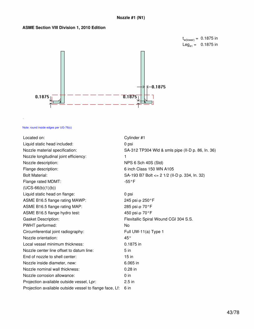
Nozzle #1 (N1)
ASME Section VIII Division 1, 2010 Edition
tw(lower) = 0.1875 inLeg41 = 0.1875 in
Note: round inside edges per UG-76(c)
Located on: Cylinder #1Liquid static head included: 0 psiNozzle material specification: SA-312 TP304 Wld & smls pipe (II-D p. 86, ln. 36)Nozzle longitudinal joint efficiency: 1Nozzle description: NPS 6 Sch 40S (Std)Flange description: 6 inch Class 150 WN A105Bolt Material: SA-193 B7 Bolt <= 2 1/2 (II-D p. 334, ln. 32)Flange rated MDMT: -55°F(UCS-66(b)(1)(b))Liquid static head on flange: 0 psiASME B16.5 flange rating MAWP: 245 psi @ 250°FASME B16.5 flange rating MAP: 285 psi @ 70°FASME B16.5 flange hydro test: 450 psi @ 70°FGasket Description: Flexitallic Spiral Wound CGI 304 S.S.PWHT performed: NoCircumferential joint radiography: Full UW-11(a) Type 1Nozzle orientation: 45°Local vessel minimum thickness: 0.1875 inNozzle center line offset to datum line: 5 inEnd of nozzle to shell center: 15 inNozzle inside diameter, new: 6.065 inNozzle nominal wall thickness: 0.28 inNozzle corrosion allowance: 0 inProjection available outside vessel, Lpr: 2.5 inProjection available outside vessel to flange face, Lf: 6 in
43/78

Reinforcement Calculations for Internal Pressure
The attached ASME B16.5 flange limits the nozzle MAWP.
UG-37 Area Calculation Summary (in2)For P = 245 psi @ 250 °F
The opening is adequately reinforced
UG-45 NozzleWall
ThicknessSummary (in)The nozzle passes
UG-45
Arequired
Aavailable A1 A2 A3 A5
Awelds treq tmin
0.6824 0.7165 0.4548 0.2265 -- -- 0.0352 0.1125 0.245
UG-41 Weld Failure Path Analysis Summary
The nozzle is exempt from weld strength calculationsper UW-15(b)(1)
UW-16 Weld Sizing Summary
Weld description Required weldthroat size (in)
Actual weldthroat size (in) Status
Nozzle to shell fillet (Leg41) 0.1312 0.1312 weld size is adequate
Calculations for internal pressure 245 psi @ 250 °F
Nozzle rated MDMT per UHA-51(d)(1)(a) = -320 °F.
Parallel Limit of reinforcement per UG-40
LR = MAX(d, Rn + (tn - Cn) + (t - C))= MAX(6.065, 3.0325 + (0.28 - 0) + (0.1875 - 0))= 6.065 in
Outer Normal Limit of reinforcement per UG-40
LH = MIN(2.5*(t - C), 2.5*(tn - Cn) + te)= MIN(2.5*(0.1875 - 0), 2.5*(0.28 - 0) + 0)= 0.4688 in
Nozzle required thickness per UG-27(c)(1)
trn = P*Rn / (Sn*E - 0.6*P)= 245*3.0325 / (19,500*1 - 0.6*245)= 0.0384 in
Required thickness tr from UG-37(a)
tr = P*Ro / (S*E + 0.4*P)= 245*9 / (19,500*1 + 0.4*245)= 0.1125 in
44/78

Area required per UG-37(c)
Allowable stresses: Sn = 19,500, Sv = 19,500 psi
fr1 = lesser of 1 or Sn / Sv = 1
fr2 = lesser of 1 or Sn / Sv = 1
A = d*tr*F + 2*tn*tr*F*(1 - fr1)= 6.065*0.1125*1 + 2*0.28*0.1125*1*(1 - 1)= 0.6824 in2
Area available from FIG. UG-37.1
A1 = larger of the following= 0.4548 in2
= d*(E1*t - F*tr) - 2*tn*(E1*t - F*tr)*(1 - fr1)= 6.065*(1*0.1875 - 1*0.1125) - 2*0.28*(1*0.1875 - 1*0.1125)*(1 - 1)= 0.4548 in2
= 2*(t + tn)*(E1*t - F*tr) - 2*tn*(E1*t - F*tr)*(1 - fr1)= 2*(0.1875 + 0.28)*(1*0.1875 - 1*0.1125) - 2*0.28*(1*0.1875 - 1*0.1125)*(1 - 1)= 0.0701 in2
A2 = smaller of the following= 0.2265 in2
= 5*(tn - trn)*fr2*t= 5*(0.28 - 0.0384)*1*0.1875= 0.2265 in2
= 5*(tn - trn)*fr2*tn= 5*(0.28 - 0.0384)*1*0.28= 0.3382 in2
A41 = Leg2*fr2= 0.18752*1= 0.0352 in2
Area = A1 + A2 + A41
= 0.4548 + 0.2265 + 0.0352= 0.7165 in2
As Area >= A the reinforcement is adequate.
45/78

UW-16(c) Weld Check
Fillet weld: tmin = lesser of 0.75 or tn or t = 0.1875 intc(min) = lesser of 0.25 or 0.7*tmin = 0.1312 intc(actual) = 0.7*Leg = 0.7*0.1875 = 0.1313 in
The fillet weld size is satisfactory.
Weld strength calculations are not required for this detail which conforms to Fig. UW-16.1, sketch (c-e).
UG-45 Nozzle Neck Thickness Check
ta UG-27 = P*R / (S*E - 0.6*P) + Corrosion= 245*3.0325 / (19,500*1 - 0.6*245) + 0= 0.0384 in
ta = max[ ta UG-27 , ta UG-22 ]= max[ 0.0384 , 0 ]= 0.0384 in
tb1 = P*Ro / (S*E + 0.4*P) + Corrosion= 245*9 / (19,500*1 + 0.4*245) + 0= 0.1125 in
tb1 = max[ tb1 , tb UG16 ]= max[ 0.1125 , 0.0625 ]= 0.1125 in
tb = min[ tb3 , tb1 ]= min[ 0.245 , 0.1125 ]= 0.1125 in
tUG-45 = max[ ta , tb ]= max[ 0.0384 , 0.1125 ]= 0.1125 in
46/78

Available nozzle wall thickness new, tn = 0.875*0.28 = 0.245 in
The nozzle neck thickness is adequate.
Reinforcement Calculations for MAP
Available reinforcement per UG-37 governs the MAP of this nozzle.
UG-37 Area Calculation Summary (in2)For P = 257.44 psi @ 70 °F
The opening is adequately reinforced
UG-45 NozzleWall
ThicknessSummary (in)The nozzle passes
UG-45
Arequired
Aavailable A1 A2 A3 A5
Awelds treq tmin
0.699 0.6991 0.4382 0.2257 -- -- 0.0352 0.1153 0.245
UG-41 Weld Failure Path Analysis Summary
The nozzle is exempt from weld strength calculationsper UW-15(b)(1)
UW-16 Weld Sizing Summary
Weld description Required weldthroat size (in)
Actual weldthroat size (in) Status
Nozzle to shell fillet (Leg41) 0.1312 0.1312 weld size is adequate
Calculations for internal pressure 257.44 psi @ 70 °F
Nozzle rated MDMT per UHA-51(d)(1)(a) = -320 °F.
Parallel Limit of reinforcement per UG-40
LR = MAX(d, Rn + (tn - Cn) + (t - C))= MAX(6.065, 3.0325 + (0.28 - 0) + (0.1875 - 0))= 6.065 in
Outer Normal Limit of reinforcement per UG-40
LH = MIN(2.5*(t - C), 2.5*(tn - Cn) + te)= MIN(2.5*(0.1875 - 0), 2.5*(0.28 - 0) + 0)= 0.4688 in
Nozzle required thickness per UG-27(c)(1)
trn = P*Rn / (Sn*E - 0.6*P)= 257.4357*3.0325 / (20,000*1 - 0.6*257.4357)= 0.0393 in
47/78

Required thickness tr from UG-37(a)
tr = P*Ro / (S*E + 0.4*P)= 257.4357*9 / (20,000*1 + 0.4*257.4357)= 0.1153 in
Area required per UG-37(c)
Allowable stresses: Sn = 20,000, Sv = 20,000 psi
fr1 = lesser of 1 or Sn / Sv = 1
fr2 = lesser of 1 or Sn / Sv = 1
A = d*tr*F + 2*tn*tr*F*(1 - fr1)= 6.065*0.1153*1 + 2*0.28*0.1153*1*(1 - 1)= 0.699 in2
Area available from FIG. UG-37.1
A1 = larger of the following= 0.4382 in2
= d*(E1*t - F*tr) - 2*tn*(E1*t - F*tr)*(1 - fr1)= 6.065*(1*0.1875 - 1*0.1153) - 2*0.28*(1*0.1875 - 1*0.1153)*(1 - 1)= 0.4382 in2
= 2*(t + tn)*(E1*t - F*tr) - 2*tn*(E1*t - F*tr)*(1 - fr1)= 2*(0.1875 + 0.28)*(1*0.1875 - 1*0.1153) - 2*0.28*(1*0.1875 - 1*0.1153)*(1 - 1)= 0.0676 in2
A2 = smaller of the following= 0.2257 in2
= 5*(tn - trn)*fr2*t= 5*(0.28 - 0.0393)*1*0.1875= 0.2257 in2
= 5*(tn - trn)*fr2*tn= 5*(0.28 - 0.0393)*1*0.28= 0.337 in2
A41 = Leg2*fr2= 0.18752*1= 0.0352 in2
Area = A1 + A2 + A41
= 0.4382 + 0.2257 + 0.0352
48/78

= 0.6991 in2
As Area >= A the reinforcement is adequate.
UW-16(c) Weld Check
Fillet weld: tmin = lesser of 0.75 or tn or t = 0.1875 intc(min) = lesser of 0.25 or 0.7*tmin = 0.1312 intc(actual) = 0.7*Leg = 0.7*0.1875 = 0.1313 in
The fillet weld size is satisfactory.
Weld strength calculations are not required for this detail which conforms to Fig. UW-16.1, sketch (c-e).
UG-45 Nozzle Neck Thickness Check
ta UG-27 = P*R / (S*E - 0.6*P) + Corrosion= 257.4357*3.0325 / (20,000*1 - 0.6*257.4357) + 0= 0.0393 in
ta = max[ ta UG-27 , ta UG-22 ]= max[ 0.0393 , 0 ]= 0.0393 in
tb1 = P*Ro / (S*E + 0.4*P) + Corrosion= 257.4357*9 / (20,000*1 + 0.4*257.4357) + 0= 0.1153 in
tb1 = max[ tb1 , tb UG16 ]= max[ 0.1153 , 0.0625 ]= 0.1153 in
tb = min[ tb3 , tb1 ]= min[ 0.245 , 0.1153 ]= 0.1153 in
tUG-45 = max[ ta , tb ]= max[ 0.0393 , 0.1153 ]= 0.1153 in
49/78
Available nozzle wall thickness new, tn = 0.875*0.28 = 0.245 in
The nozzle neck thickness is adequate.
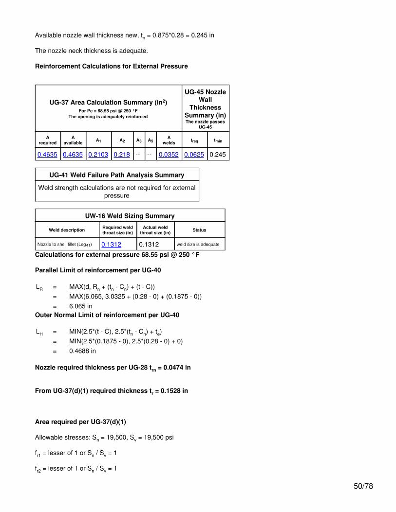
Reinforcement Calculations for External Pressure
UG-37 Area Calculation Summary (in2)For Pe = 68.55 psi @ 250 °F
The opening is adequately reinforced
UG-45 NozzleWall
ThicknessSummary (in)The nozzle passes
UG-45
Arequired
Aavailable A1 A2 A3 A5
Awelds treq tmin
0.4635 0.4635 0.2103 0.218 -- -- 0.0352 0.0625 0.245
UG-41 Weld Failure Path Analysis Summary
Weld strength calculations are not required for externalpressure
UW-16 Weld Sizing Summary
Weld description Required weldthroat size (in)
Actual weldthroat size (in) Status
Nozzle to shell fillet (Leg41) 0.1312 0.1312 weld size is adequate
Calculations for external pressure 68.55 psi @ 250 °F
Parallel Limit of reinforcement per UG-40
LR = MAX(d, Rn + (tn - Cn) + (t - C))= MAX(6.065, 3.0325 + (0.28 - 0) + (0.1875 - 0))= 6.065 in
Outer Normal Limit of reinforcement per UG-40
LH = MIN(2.5*(t - C), 2.5*(tn - Cn) + te)= MIN(2.5*(0.1875 - 0), 2.5*(0.28 - 0) + 0)= 0.4688 in
Nozzle required thickness per UG-28 trn = 0.0474 in
From UG-37(d)(1) required thickness tr = 0.1528 in
Area required per UG-37(d)(1)
Allowable stresses: Sn = 19,500, Sv = 19,500 psi
fr1 = lesser of 1 or Sn / Sv = 1
fr2 = lesser of 1 or Sn / Sv = 1
50/78

A = 0.5*(d*tr*F + 2*tn*tr*F*(1 - fr1))= 0.5*(6.065*0.1528*1 + 2*0.28*0.1528*1*(1 - 1))= 0.4635 in2
Area available from FIG. UG-37.1
A1 = larger of the following= 0.2103 in2
= d*(E1*t - F*tr) - 2*tn*(E1*t - F*tr)*(1 - fr1)= 6.065*(1*0.1875 - 1*0.1528) - 2*0.28*(1*0.1875 - 1*0.1528)*(1 - 1)= 0.2103 in2
= 2*(t + tn)*(E1*t - F*tr) - 2*tn*(E1*t - F*tr)*(1 - fr1)= 2*(0.1875 + 0.28)*(1*0.1875 - 1*0.1528) - 2*0.28*(1*0.1875 - 1*0.1528)*(1 - 1)= 0.0324 in2
A2 = smaller of the following= 0.218 in2
= 5*(tn - trn)*fr2*t= 5*(0.28 - 0.0474)*1*0.1875= 0.218 in2
= 5*(tn - trn)*fr2*tn= 5*(0.28 - 0.0474)*1*0.28= 0.3256 in2
A41 = Leg2*fr2= 0.18752*1= 0.0352 in2
Area = A1 + A2 + A41
= 0.2103 + 0.218 + 0.0352= 0.4635 in2
As Area >= A the reinforcement is adequate.
UW-16(c) Weld Check
Fillet weld: tmin = lesser of 0.75 or tn or t = 0.1875 intc(min) = lesser of 0.25 or 0.7*tmin = 0.1312 intc(actual) = 0.7*Leg = 0.7*0.1875 = 0.1313 in
The fillet weld size is satisfactory.
Weld strength calculations are not required for this detail which conforms to Fig. UW-16.1, sketch (c-e).
51/78

UG-45 Nozzle Neck Thickness Check
ta UG-28 = 0.0474 in
ta = max[ ta UG-28 , ta UG-22 ]= max[ 0.0474 , 0 ]= 0.0474 in
tb2 = P*Ro / (S*E + 0.4*P) + Corrosion= 68.549*9 / (19,500*1 + 0.4*68.549) + 0= 0.0316 in
tb2 = max[ tb2 , tb UG16 ]= max[ 0.0316 , 0.0625 ]= 0.0625 in
tb = min[ tb3 , tb2 ]= min[ 0.245 , 0.0625 ]= 0.0625 in
tUG-45 = max[ ta , tb ]= max[ 0.0474 , 0.0625 ]= 0.0625 in
Available nozzle wall thickness new, tn = 0.875*0.28 = 0.245 in
The nozzle neck thickness is adequate.
External Pressure, (Corroded & at 250 °F) UG-28(c)
L /Do
= 6.6318 /6.625 = 1.0010
Do/ t = 6.625 /
0.0474 = 139.6917
From table G: A = 0.000820From tableHA-1: B = 7,181.8008
psi
Pa = 4*B / (3*(Do / t))
= 4*7,181.8 / (3*(6.625 /0.0474))
= 68.55 psi
Design thickness for external pressure Pa = 68.55 psi
ta = t +Corrosion = 0.0474
+ 0 = 0.0474"
52/78

Copy of Nozzle #1 (N2)
ASME Section VIII Division 1, 2010 Edition
tw(lower) = 0.1875 inLeg41 = 0.1875 in
Note: round inside edges per UG-76(c)
Located on: Cylinder #1Liquid static head included: 0 psiNozzle material specification: SA-106 B Smls pipe (II-D p. 10, ln. 40)Nozzle longitudinal joint efficiency: 1Nozzle description: NPS 6 Sch 40 (Std)Flange description: 6 inch Class 300 WN A105Bolt Material: SA-193 B7 Bolt <= 2 1/2 (II-D p. 334, ln. 32)Flange rated MDMT: -55°F(UCS-66(b)(3): Coincident ratio = 0.2027027)(Flange rated MDMT = -155 °FBolts rated MDMT per Fig UCS-66 note (c) = -55 °F)Liquid static head on flange: 0 psiASME B16.5 flange rating MAWP: 667.5 psi @ 250°FASME B16.5 flange rating MAP: 740 psi @ 70°FASME B16.5 flange hydro test: 1125 psi @ 70°FGasket Description: Flexitallic Spiral Wound CGI 304 S.S.PWHT performed: NoCircumferential joint radiography: Full UW-11(a) Type 1Nozzle orientation: 225°Local vessel minimum thickness: 0.1875 inNozzle center line offset to datum line: 22 inEnd of nozzle to shell center: 15 inNozzle inside diameter, new: 6.065 inNozzle nominal wall thickness: 0.28 inNozzle corrosion allowance: 0 inProjection available outside vessel, Lpr: 2.12 inProjection available outside vessel to flange face, Lf: 6 in
53/78

Reinforcement Calculations for Internal Pressure
Available reinforcement per UG-37 governs the MAWP of this nozzle.
UG-37 Area Calculation Summary (in2)For P = 242.26 psi @ 250 °F
The opening is adequately reinforced
UG-45 NozzleWall
ThicknessSummary (in)The nozzle passes
UG-45
Arequired
Aavailable A1 A2 A3 A5
Awelds treq tmin
0.6825 0.6825 0.4571 0.1946 -- -- 0.0308 0.1113 0.245
UG-41 Weld Failure Path Analysis Summary
The nozzle is exempt from weld strength calculationsper UW-15(b)(1)
UW-16 Weld Sizing Summary
Weld description Required weldthroat size (in)
Actual weldthroat size (in) Status
Nozzle to shell fillet (Leg41) 0.1312 0.1312 weld size is adequate
Calculations for internal pressure 242.26 psi @ 250 °F
Fig UCS-66.2 general note (1) applies.
Nozzle impact test exemption temperature from Fig UCS-66 Curve B = -20 °FFig UCS-66.1 MDMT reduction = 130.8 °F, (coincident ratio = 0.35893)Rated MDMT is governed by UCS-66(b)(2).
Nozzle UCS-66 governing thk: 0.1875 inNozzle rated MDMT: -55 °FParallel Limit of reinforcement per UG-40
LR = MAX(d, Rn + (tn - Cn) + (t - C))= MAX(6.065, 3.0325 + (0.28 - 0) + (0.1875 - 0))= 6.065 in
Outer Normal Limit of reinforcement per UG-40
LH = MIN(2.5*(t - C), 2.5*(tn - Cn) + te)= MIN(2.5*(0.1875 - 0), 2.5*(0.28 - 0) + 0)= 0.4688 in
Nozzle required thickness per UG-27(c)(1)
trn = P*Rn / (Sn*E - 0.6*P)= 242.2648*3.0325 / (17,100*1 - 0.6*242.2648)
54/78

= 0.0433 in
Required thickness tr from UG-37(a)
tr = P*Ro / (S*E + 0.4*P)= 242.2648*9 / (19,500*1 + 0.4*242.2648)= 0.1113 in
Area required per UG-37(c)
Allowable stresses: Sn = 17,100, Sv = 19,500 psi
fr1 = lesser of 1 or Sn / Sv = 0.8769
fr2 = lesser of 1 or Sn / Sv = 0.8769
A = d*tr*F + 2*tn*tr*F*(1 - fr1)= 6.065*0.1113*1 + 2*0.28*0.1113*1*(1 - 0.8769)= 0.6825 in2
Area available from FIG. UG-37.1
A1 = larger of the following= 0.4571 in2
= d*(E1*t - F*tr) - 2*tn*(E1*t - F*tr)*(1 - fr1)= 6.065*(1*0.1875 - 1*0.1113) - 2*0.28*(1*0.1875 - 1*0.1113)*(1 - 0.8769)= 0.4571 in2
= 2*(t + tn)*(E1*t - F*tr) - 2*tn*(E1*t - F*tr)*(1 - fr1)= 2*(0.1875 + 0.28)*(1*0.1875 - 1*0.1113) - 2*0.28*(1*0.1875 - 1*0.1113)*(1 - 0.8769)= 0.066 in2
A2 = smaller of the following= 0.1946 in2
= 5*(tn - trn)*fr2*t= 5*(0.28 - 0.0433)*0.8769*0.1875= 0.1946 in2
= 5*(tn - trn)*fr2*tn= 5*(0.28 - 0.0433)*0.8769*0.28= 0.2906 in2
A41 = Leg2*fr2= 0.18752*0.8769= 0.0308 in2
55/78

Area = A1 + A2 + A41
= 0.4571 + 0.1946 + 0.0308= 0.6825 in2
As Area >= A the reinforcement is adequate.
UW-16(c) Weld Check
Fillet weld: tmin = lesser of 0.75 or tn or t = 0.1875 intc(min) = lesser of 0.25 or 0.7*tmin = 0.1312 intc(actual) = 0.7*Leg = 0.7*0.1875 = 0.1313 in
The fillet weld size is satisfactory.
Weld strength calculations are not required for this detail which conforms to Fig. UW-16.1, sketch (c-e).
UG-45 Nozzle Neck Thickness Check
ta UG-27 = P*R / (S*E - 0.6*P) + Corrosion= 242.2648*3.0325 / (17,100*1 - 0.6*242.2648) + 0= 0.0433 in
ta = max[ ta UG-27 , ta UG-22 ]= max[ 0.0433 , 0 ]= 0.0433 in
tb1 = P*Ro / (S*E + 0.4*P) + Corrosion= 242.2648*9 / (19,500*1 + 0.4*242.2648) + 0= 0.1113 in
tb1 = max[ tb1 , tb UG16 ]= max[ 0.1113 , 0.0625 ]= 0.1113 in
tb = min[ tb3 , tb1 ]= min[ 0.245 , 0.1113 ]= 0.1113 in
tUG-45 = max[ ta , tb ]= max[ 0.0433 , 0.1113 ]= 0.1113 in
56/78

Available nozzle wall thickness new, tn = 0.875*0.28 = 0.245 in
The nozzle neck thickness is adequate.
Reinforcement Calculations for MAP
Available reinforcement per UG-37 governs the MAP of this nozzle.
UG-37 Area Calculation Summary (in2)For P = 246.89 psi @ 70 °F
The opening is adequately reinforced
UG-45 NozzleWall
ThicknessSummary (in)The nozzle passes
UG-45
Arequired
Aavailable A1 A2 A3 A5
Awelds treq tmin
0.6795 0.6796 0.4605 0.189 -- -- 0.0301 0.1106 0.245
UG-41 Weld Failure Path Analysis Summary
The nozzle is exempt from weld strength calculationsper UW-15(b)(1)
UW-16 Weld Sizing Summary
Weld description Required weldthroat size (in)
Actual weldthroat size (in) Status
Nozzle to shell fillet (Leg41) 0.1312 0.1312 weld size is adequate
Calculations for internal pressure 246.89 psi @ 70 °F
Parallel Limit of reinforcement per UG-40
LR = MAX(d, Rn + (tn - Cn) + (t - C))= MAX(6.065, 3.0325 + (0.28 - 0) + (0.1875 - 0))= 6.065 in
Outer Normal Limit of reinforcement per UG-40
LH = MIN(2.5*(t - C), 2.5*(tn - Cn) + te)= MIN(2.5*(0.1875 - 0), 2.5*(0.28 - 0) + 0)= 0.4688 in
Nozzle required thickness per UG-27(c)(1)
trn = P*Rn / (Sn*E - 0.6*P)= 246.8865*3.0325 / (17,100*1 - 0.6*246.8865)= 0.0442 in
Required thickness tr from UG-37(a)
tr = P*Ro / (S*E + 0.4*P)= 246.8865*9 / (20,000*1 + 0.4*246.8865)
57/78

= 0.1106 in
Area required per UG-37(c)
Allowable stresses: Sn = 17,100, Sv = 20,000 psi
fr1 = lesser of 1 or Sn / Sv = 0.855
fr2 = lesser of 1 or Sn / Sv = 0.855
A = d*tr*F + 2*tn*tr*F*(1 - fr1)= 6.065*0.1106*1 + 2*0.28*0.1106*1*(1 - 0.855)= 0.6795 in2
Area available from FIG. UG-37.1
A1 = larger of the following= 0.4605 in2
= d*(E1*t - F*tr) - 2*tn*(E1*t - F*tr)*(1 - fr1)= 6.065*(1*0.1875 - 1*0.1106) - 2*0.28*(1*0.1875 - 1*0.1106)*(1 - 0.855)= 0.4605 in2
= 2*(t + tn)*(E1*t - F*tr) - 2*tn*(E1*t - F*tr)*(1 - fr1)= 2*(0.1875 + 0.28)*(1*0.1875 - 1*0.1106) - 2*0.28*(1*0.1875 - 1*0.1106)*(1 - 0.855)= 0.0657 in2
A2 = smaller of the following= 0.189 in2
= 5*(tn - trn)*fr2*t= 5*(0.28 - 0.0442)*0.855*0.1875= 0.189 in2
= 5*(tn - trn)*fr2*tn= 5*(0.28 - 0.0442)*0.855*0.28= 0.2823 in2
A41 = Leg2*fr2= 0.18752*0.855= 0.0301 in2
Area = A1 + A2 + A41
= 0.4605 + 0.189 + 0.0301= 0.6796 in2
As Area >= A the reinforcement is adequate.
58/78

UW-16(c) Weld Check
Fillet weld: tmin = lesser of 0.75 or tn or t = 0.1875 intc(min) = lesser of 0.25 or 0.7*tmin = 0.1312 intc(actual) = 0.7*Leg = 0.7*0.1875 = 0.1313 in
The fillet weld size is satisfactory.
Weld strength calculations are not required for this detail which conforms to Fig. UW-16.1, sketch (c-e).
UG-45 Nozzle Neck Thickness Check
ta UG-27 = P*R / (S*E - 0.6*P) + Corrosion= 246.8865*3.0325 / (17,100*1 - 0.6*246.8865) + 0= 0.0442 in
ta = max[ ta UG-27 , ta UG-22 ]= max[ 0.0442 , 0 ]= 0.0442 in
tb1 = P*Ro / (S*E + 0.4*P) + Corrosion= 246.8865*9 / (20,000*1 + 0.4*246.8865) + 0= 0.1106 in
tb1 = max[ tb1 , tb UG16 ]= max[ 0.1106 , 0.0625 ]= 0.1106 in
tb = min[ tb3 , tb1 ]= min[ 0.245 , 0.1106 ]= 0.1106 in
tUG-45 = max[ ta , tb ]= max[ 0.0442 , 0.1106 ]= 0.1106 in
59/78

Available nozzle wall thickness new, tn = 0.875*0.28 = 0.245 in
The nozzle neck thickness is adequate.
Reinforcement Calculations for External Pressure
UG-37 Area Calculation Summary (in2)For Pe = 66.07 psi @ 250 °F
The opening is adequately reinforced
UG-45 NozzleWall
ThicknessSummary (in)The nozzle passes
UG-45
Arequired
Aavailable A1 A2 A3 A5
Awelds treq tmin
0.4582 0.4583 0.2285 0.199 -- -- 0.0308 0.0625 0.245
UG-41 Weld Failure Path Analysis Summary
Weld strength calculations are not required for externalpressure
UW-16 Weld Sizing Summary
Weld description Required weldthroat size (in)
Actual weldthroat size (in) Status
Nozzle to shell fillet (Leg41) 0.1312 0.1312 weld size is adequate
Calculations for external pressure 66.07 psi @ 250 °F
Parallel Limit of reinforcement per UG-40
LR = MAX(d, Rn + (tn - Cn) + (t - C))= MAX(6.065, 3.0325 + (0.28 - 0) + (0.1875 - 0))= 6.065 in
Outer Normal Limit of reinforcement per UG-40
LH = MIN(2.5*(t - C), 2.5*(tn - Cn) + te)= MIN(2.5*(0.1875 - 0), 2.5*(0.28 - 0) + 0)= 0.4688 in
Nozzle required thickness per UG-28 trn = 0.038 in
From UG-37(d)(1) required thickness tr = 0.1494 in
Area required per UG-37(d)(1)
Allowable stresses: Sn = 17,100, Sv = 19,500 psi
fr1 = lesser of 1 or Sn / Sv = 0.8769
fr2 = lesser of 1 or Sn / Sv = 0.8769
60/78

A = 0.5*(d*tr*F + 2*tn*tr*F*(1 - fr1))= 0.5*(6.065*0.1494*1 + 2*0.28*0.1494*1*(1 - 0.8769))= 0.4582 in2
Area available from FIG. UG-37.1
A1 = larger of the following= 0.2285 in2
= d*(E1*t - F*tr) - 2*tn*(E1*t - F*tr)*(1 - fr1)= 6.065*(1*0.1875 - 1*0.1494) - 2*0.28*(1*0.1875 - 1*0.1494)*(1 - 0.8769)= 0.2285 in2
= 2*(t + tn)*(E1*t - F*tr) - 2*tn*(E1*t - F*tr)*(1 - fr1)= 2*(0.1875 + 0.28)*(1*0.1875 - 1*0.1494) - 2*0.28*(1*0.1875 - 1*0.1494)*(1 - 0.8769)= 0.033 in2
A2 = smaller of the following= 0.199 in2
= 5*(tn - trn)*fr2*t= 5*(0.28 - 0.038)*0.8769*0.1875= 0.199 in2
= 5*(tn - trn)*fr2*tn= 5*(0.28 - 0.038)*0.8769*0.28= 0.2971 in2
A41 = Leg2*fr2= 0.18752*0.8769= 0.0308 in2
Area = A1 + A2 + A41
= 0.2285 + 0.199 + 0.0308= 0.4583 in2
As Area >= A the reinforcement is adequate.
UW-16(c) Weld Check
Fillet weld: tmin = lesser of 0.75 or tn or t = 0.1875 intc(min) = lesser of 0.25 or 0.7*tmin = 0.1312 intc(actual) = 0.7*Leg = 0.7*0.1875 = 0.1313 in
The fillet weld size is satisfactory.
Weld strength calculations are not required for this detail which conforms to Fig. UW-16.1, sketch (c-e).
61/78

UG-45 Nozzle Neck Thickness Check
ta UG-28 = 0.038 in
ta = max[ ta UG-28 , ta UG-22 ]= max[ 0.038 , 0 ]= 0.038 in
tb2 = P*Ro / (S*E + 0.4*P) + Corrosion= 66.0717*9 / (19,500*1 + 0.4*66.0717) + 0= 0.0305 in
tb2 = max[ tb2 , tb UG16 ]= max[ 0.0305 , 0.0625 ]= 0.0625 in
tb = min[ tb3 , tb2 ]= min[ 0.245 , 0.0625 ]= 0.0625 in
tUG-45 = max[ ta , tb ]= max[ 0.038 , 0.0625 ]= 0.0625 in
Available nozzle wall thickness new, tn = 0.875*0.28 = 0.245 in
The nozzle neck thickness is adequate.
External Pressure, (Corroded & at 250 °F) UG-28(c)
L /Do
= 6.6318 /6.625 = 1.0010
Do /t = 6.625 /
0.038 = 174.4501
From table G: A = 0.000600From tableCS-2: B = 8,644.7656
psi
Pa = 4*B / (3*(Do / t))
= 4*8,644.77 / (3*(6.625 /0.038))
= 66.07 psi
Design thickness for external pressure Pa = 66.07 psi
ta = t +Corrosion = 0.038
+ 0 = 0.038"
62/78

Nozzle #3 (N3)
ASME Section VIII Division 1, 2010 Edition
tw(lower) = 0 inLeg41 = 0.3125 in
Note: round inside edges per UG-76(c)
Located on: Cylinder #1Liquid static head included: 0 psiNozzle material specification: SA-105 (II-D p. 18, ln. 5)Nozzle longitudinal joint efficiency: 1Nozzle description: NPS 1 Class 3000 - threadedNozzle orientation: 300°Local vessel minimum thickness: 0.1875 inNozzle center line offset to datum line: 7 inEnd of nozzle to shell center: 11 inNozzle inside diameter, new: 1.315 inNozzle nominal wall thickness: 0.2175 inNozzle corrosion allowance: 0 inProjection available outside vessel, Lpr: 2 in
63/78

Reinforcement Calculations for Internal Pressure
The vessel wall thickness governs the MAWP of this nozzle.
UG-37 Area Calculation Summary(in2)
For P = 409.67 psi @ 250 °F
UG-45 NozzleWall
ThicknessSummary (in)The nozzle passes
UG-45
Arequired
Aavailable A1 A2 A3 A5
Awelds treq tmin
This nozzle is exempt from areacalculations per UG-36(c)(3)(a) 0.0625 0.2175
UG-41 Weld Failure Path Analysis Summary
The nozzle is exempt from weld strength calculationsper UW-15(b)(2)
UW-16 Weld Sizing Summary
Weld description Required weldthroat size (in)
Actual weldthroat size (in) Status
Nozzle to shell fillet (Leg41) 0.1268 0.2188 weld size is adequate
Calculations for internal pressure 409.67 psi @ 250 °F
Nozzle impact test exemption temperature from Fig UCS-66 Curve B = -20 °FFig UCS-66.1 MDMT reduction = 130.8 °F, (coincident ratio = 0.35893)Rated MDMT is governed by UCS-66(b)(2).
Nozzle UCS-66 governing thk: 0.1875 inNozzle rated MDMT: -55 °FParallel Limit of reinforcement per UG-40
LR = MAX(d, Rn + (tn - Cn) + (t - C))= MAX(1.315, 0.6575 + (0.2175 - 0) + (0.1875 - 0))= 1.315 in
Outer Normal Limit of reinforcement per UG-40
LH = MIN(2.5*(t - C), 2.5*(tn - Cn) + te)= MIN(2.5*(0.1875 - 0), 2.5*(0.2175 - 0) + 0)= 0.4688 in
Nozzle required thickness per UG-27(c)(1)
trn = P*Rn / (Sn*E - 0.6*P)= 409.6698*0.6575 / (20,000*1 - 0.6*409.6698)= 0.0136 in
64/78

Required thickness tr from UG-37(a)
tr = P*Ro / (S*E + 0.4*P)= 409.6698*9 / (19,500*1 + 0.4*409.6698)= 0.1875 in
This opening does not require reinforcement per UG-36(c)(3)(a)
Check the weld - From UW-16(f)(3)(a)(3)(a)
Wall thickness per UG-45(a): tr1 = 0.0178 in (E =1)Wall thickness per UG-45(b)(1): tr2 = 0.1875 inWall thickness per UG-16(b): tr3 = 0.0625 inStandard wall pipe per UG-45(b)(4): tr4 = 0.1269 inThe greater of tr2 or tr3: tr5 = 0.1875 inThe lesser of tr4 or tr5: tr6 = 0.1269 in
Required per UG-45 is the larger of tr1 or tr6 = 0.1269 in
tw(actual) = 0.7*Leg = 0.7*0.3125 = 0.2188 in
The fillet weld size is satisfactory.
ASME B16.11 Coupling Wall Thickness Check
Wall thickness req'd per ASME B16.11 2.1.1: tr1 = 0.0178 in (E =1)Wall thickness per UG-16(b): tr3 = 0.0625 in
65/78

Available nozzle wall thickness new, tn = 0.2175 in
The nozzle neck thickness is adequate.
Reinforcement Calculations for MAP
The vessel wall thickness governs the MAP of this nozzle.
UG-37 Area Calculation Summary(in2)
For P = 420.17 psi @ 70 °F
UG-45 NozzleWall
ThicknessSummary (in)The nozzle passes
UG-45
Arequired
Aavailable A1 A2 A3 A5
Awelds treq tmin
This nozzle is exempt from areacalculations per UG-36(c)(3)(a) 0.0625 0.2175
UG-41 Weld Failure Path Analysis Summary
The nozzle is exempt from weld strength calculationsper UW-15(b)(2)
UW-16 Weld Sizing Summary
Weld description Required weldthroat size (in)
Actual weldthroat size (in) Status
Nozzle to shell fillet (Leg41) 0.1268 0.2188 weld size is adequate
Calculations for internal pressure 420.17 psi @ 70 °F
Parallel Limit of reinforcement per UG-40
LR = MAX(d, Rn + (tn - Cn) + (t - C))= MAX(1.315, 0.6575 + (0.2175 - 0) + (0.1875 - 0))= 1.315 in
Outer Normal Limit of reinforcement per UG-40
LH = MIN(2.5*(t - C), 2.5*(tn - Cn) + te)= MIN(2.5*(0.1875 - 0), 2.5*(0.2175 - 0) + 0)= 0.4688 in
Nozzle required thickness per UG-27(c)(1)
trn = P*Rn / (Sn*E - 0.6*P)= 420.172*0.6575 / (20,000*1 - 0.6*420.172)= 0.014 in
66/78

Required thickness tr from UG-37(a)
tr = P*Ro / (S*E + 0.4*P)= 420.172*9 / (20,000*1 + 0.4*420.172)= 0.1875 in
This opening does not require reinforcement per UG-36(c)(3)(a)
Check the weld - From UW-16(f)(3)(a)(3)(a)
Wall thickness per UG-45(a): tr1 = 0.0182 in (E =1)Wall thickness per UG-45(b)(1): tr2 = 0.1875 inWall thickness per UG-16(b): tr3 = 0.0625 inStandard wall pipe per UG-45(b)(4): tr4 = 0.1269 inThe greater of tr2 or tr3: tr5 = 0.1875 inThe lesser of tr4 or tr5: tr6 = 0.1269 in
Required per UG-45 is the larger of tr1 or tr6 = 0.1269 in
tw(actual) = 0.7*Leg = 0.7*0.3125 = 0.2188 in
The fillet weld size is satisfactory.
ASME B16.11 Coupling Wall Thickness Check
Wall thickness req'd per ASME B16.11 2.1.1: tr1 = 0.0182 in (E =1)Wall thickness per UG-16(b): tr3 = 0.0625 in
67/78

Available nozzle wall thickness new, tn = 0.2175 in
The nozzle neck thickness is adequate.
Reinforcement Calculations for External Pressure
UG-37 Area Calculation Summary(in2)
For Pe = 93.73 psi @ 250 °F
UG-45 NozzleWall
ThicknessSummary (in)The nozzle passes
UG-45
Arequired
Aavailable A1 A2 A3 A5
Awelds treq tmin
This nozzle is exempt from areacalculations per UG-36(c)(3)(a) 0.0625 0.2175
UG-41 Weld Failure Path Analysis Summary
Weld strength calculations are not required for externalpressure
UW-16 Weld Sizing Summary
Weld description Required weldthroat size (in)
Actual weldthroat size (in) Status
Nozzle to shell fillet (Leg41) 0.0625 0.2188 weld size is adequate
Calculations for external pressure 93.73 psi @ 250 °F
Parallel Limit of reinforcement per UG-40
LR = MAX(d, Rn + (tn - Cn) + (t - C))= MAX(1.315, 0.6575 + (0.2175 - 0) + (0.1875 - 0))= 1.315 in
Outer Normal Limit of reinforcement per UG-40
LH = MIN(2.5*(t - C), 2.5*(tn - Cn) + te)= MIN(2.5*(0.1875 - 0), 2.5*(0.2175 - 0) + 0)= 0.4688 in
Nozzle required thickness per UG-28 trn = 0.0124 in
From UG-37(d)(1) required thickness tr = 0.1875 in
This opening does not require reinforcement per UG-36(c)(3)(a)
68/78

Check the weld - From UW-16(f)(3)(a)(3)(a)
Wall thickness per UG-45(a): tr1 = 0.0124 inWall thickness per UG-45(b)(1): tr2 = 0.0432 inWall thickness per UG-16(b): tr3 = 0.0625 inStandard wall pipe per UG-45(b)(4): tr4 = 0.1269 inThe greater of tr2 or tr3: tr5 = 0.0625 inThe lesser of tr4 or tr5: tr6 = 0.0625 in
Required per UG-45 is the larger of tr1 or tr6 = 0.0625 in
tw(actual) = 0.7*Leg = 0.7*0.3125 = 0.2188 in
The fillet weld size is satisfactory.
UG-45 Nozzle Neck Thickness Check
ta UG-28 = 0.0124 in
ta = max[ ta UG-28 , ta UG-22 ]= max[ 0.0124 , 0 ]= 0.0124 in
tb2 = P*Ro / (S*E + 0.4*P) + Corrosion= 93.7331*9 / (19,500*1 + 0.4*93.7331) + 0= 0.0432 in
tb2 = max[ tb2 , tb UG16 ]= max[ 0.0432 , 0.0625 ]= 0.0625 in
tb = min[ tb3 , tb2 ]= min[ 0.1269 , 0.0625 ]= 0.0625 in
tUG-45 = max[ ta , tb ]= max[ 0.0124 , 0.0625 ]= 0.0625 in
Available nozzle wall thickness new, tn = 0.2175 in
The nozzle neck thickness is adequate.
External Pressure, (Corroded & at 250 °F) UG-28(c)
L /Do
= 2.0426 /1.75 = 1.1672
Do/ t = 1.75 /
0.0124 = 140.9503
From table G: A = 0.000687B =
69/78
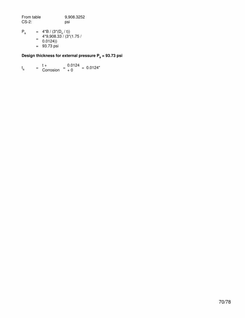
From tableCS-2:
9,908.3252psi
Pa = 4*B / (3*(Do / t))
= 4*9,908.33 / (3*(1.75 /0.0124))
= 93.73 psi
Design thickness for external pressure Pa = 93.73 psi
ta = t +Corrosion = 0.0124
+ 0 = 0.0124"
70/78

Straight Flange on F&D Head #1
ASME Section VIII Division 1, 2010 Edition
Component: Straight FlangeMaterial specification: SA-240 304 (II-D p. 86, ln. 25)Rated MDMT per UHA-51(d)(1)(a) = -320 °F
Internal design pressure: P = 150 psi @ 250 °FExternal design pressure: Pe = 15 psi @ 250 °F
Static liquid head:
Pth = 0.78 psi (SG = 1, Hs = 21.6259", Horizontal testhead)
Corrosion allowance Inner C = 0" Outer C = 0"
Design MDMT = -20 °F No impact test performedRated MDMT = -320 °F Material is not normalized
Material is not produced to Fine Grain PracticePWHT is not performed
Radiography: Longitudinal joint - Spot UW-11(b) Type 1Circumferential joint - UserDefined
E = 0.5
Estimated weight New = 4.1 lb corr = 4.1 lbCapacity New = 2.14 US gal corr = 2.14 US gal
OD = 18"LengthLc
= 2"
t = 0.125"
Design thickness, (at 250 °F) Appendix 1-1
t = P*Ro / (S*E + 0.40*P) + Corrosion= 150*9 / (19,500*0.85 + 0.40*150) + 0= 0.0812"
Maximum allowable working pressure, (at 250 °F) Appendix 1-1
P = S*E*t / (Ro - 0.40*t) - Ps= 19,500*0.85*0.125 / (9 - 0.40*0.125) - 0= 231.49 psi
Maximum allowable pressure, (at 70 °F) Appendix 1-1
P = S*E*t / (Ro - 0.40*t)= 20,000*0.85*0.125 / (9 - 0.40*0.125)= 237.43 psi
External Pressure, (Corroded & at 250 °F) UG-28(c)
L /Do
= 36.1178/ 18 = 2.0065
71/78

Do/ t = 18 /
0.0791 = 227.4320
From table G: A = 0.000191From tableHA-1: B = 2,558.6055
psi
Pa = 4*B / (3*(Do / t))
= 4*2,558.61 / (3*(18 /0.0791))
= 15 psi
Design thickness for external pressure Pa = 15 psi
ta = t +Corrosion = 0.0791
+ 0 = 0.0791"
Maximum Allowable External Pressure, (Corroded & at 250 °F) UG-28(c)
L /Do
= 36.1178/ 18 = 2.0065
Do/ t = 18 /
0.125 = 144.0000
From table G: A = 0.000374From tableHA-1: B = 5,012.4644
psi
Pa = 4*B / (3*(Do / t))
= 4*5,012.46 / (3*(18 /0.125))
= 46.41 psi
% Forming strain - UHA-44(a)(2)(a)
EFE = (50*t / Rf)*(1 - Rf / Ro)= (50*0.125 / 8.9375)*(1 - 8.9375 / ∞)= 0.6993%
Design thickness = 0.0812"
The governing condition is due to internal pressure.
The cylinder thickness of 0.125" is adequate.
Thickness Required Due to Pressure + External Loads
Condition Pressure P (psi)
Allowable StressBefore UG-23
Stress Increase (psi)
Temperature (°F)
Corrosion C(in) Load Req'd Thk Due to
Tension (in)
Req'd Thk Dueto
Compression(in)
St Sc
Operating, Hot & Corroded 150 19,500 9,316 250 0 Weight 0.0681 0.0681
Operating, Hot & New 150 19,500 9,316 250 0 Weight 0.0681 0.0681
Hot Shut Down, Corroded 0 19,500 9,316 250 0 Weight 0 0
Hot Shut Down, New 0 19,500 9,316 250 0 Weight 0 0
Empty, Corroded 0 20,000 11,048 70 0 Weight 0 0
72/78

Empty, New 0 20,000 11,048 70 0 Weight 0 0
Vacuum -15 19,500 9,316 250 0 Weight 0.0071 0.0071
Hot Shut Down, Corroded, Weight& Eccentric Moments Only 0 19,500 9,316 250 0 Weight 0 0
Allowable Compressive Stress, Hot and Corroded- ScHC, (table HA-1)A = 0.125 / (Ro / t)
= 0.125 / (9 / 0.125)= 0.001736
B = 9,316 psi
S = 19,500 / 1.00 = 19,500 psi
ScHC = min(B, S) = 9,316 psi
Allowable Compressive Stress, Hot and New- ScHN
ScHN = ScHC
= 9,316 psi
Allowable Compressive Stress, Cold and New- ScCN, (table HA-1)A = 0.125 / (Ro / t)
= 0.125 / (9 / 0.125)= 0.001736
B = 11,048 psi
S = 20,000 / 1.00 = 20,000 psi
ScCN = min(B, S) = 11,048 psi
Allowable Compressive Stress, Cold and Corroded- ScCC
ScCC = ScCN
= 11,048 psi
Allowable Compressive Stress, Vacuum and Corroded- ScVC, (table HA-1)A = 0.125 / (Ro / t)
= 0.125 / (9 / 0.125)= 0.001736
B = 9,316 psi
S = 19,500 / 1.00 = 19,500 psi
ScVC = min(B, S) = 9,316 psi
Operating, Hot & Corroded, Top Seam
tp = P*R / (2*St*Ks*Ec + 0.40*|P|) (Pressure)= 150*8.875 / (2*19,500*1.00*0.50 + 0.40*|150|)= 0.0681"
tm = M / (π*Rm2*St*Ks*Ec) (bending)
= 0 / (π*8.93752*19,500*1.00*0.50)= 0"
73/78
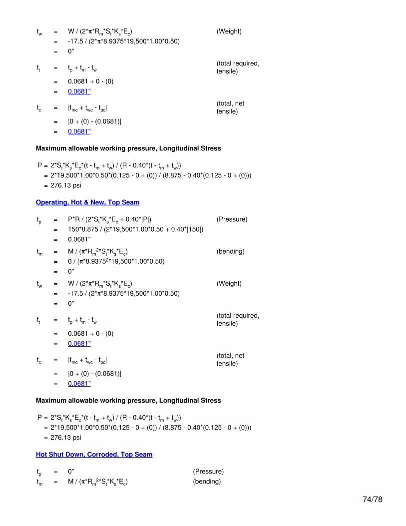
tw = W / (2*π*Rm*St*Ks*Ec) (Weight)= -17.5 / (2*π*8.9375*19,500*1.00*0.50)= 0"
tt = tp + tm - tw(total required,tensile)
= 0.0681 + 0 - (0)= 0.0681"
tc = |tmc + twc - tpc|(total, nettensile)
= |0 + (0) - (0.0681)|= 0.0681"
Maximum allowable working pressure, Longitudinal Stress
P = 2*St*Ks*Ec*(t - tm + tw) / (R - 0.40*(t - tm + tw))= 2*19,500*1.00*0.50*(0.125 - 0 + (0)) / (8.875 - 0.40*(0.125 - 0 + (0)))= 276.13 psi
Operating, Hot & New, Top Seam
tp = P*R / (2*St*Ks*Ec + 0.40*|P|) (Pressure)= 150*8.875 / (2*19,500*1.00*0.50 + 0.40*|150|)= 0.0681"
tm = M / (π*Rm2*St*Ks*Ec) (bending)
= 0 / (π*8.93752*19,500*1.00*0.50)= 0"
tw = W / (2*π*Rm*St*Ks*Ec) (Weight)= -17.5 / (2*π*8.9375*19,500*1.00*0.50)= 0"
tt = tp + tm - tw(total required,tensile)
= 0.0681 + 0 - (0)= 0.0681"
tc = |tmc + twc - tpc|(total, nettensile)
= |0 + (0) - (0.0681)|= 0.0681"
Maximum allowable working pressure, Longitudinal Stress
P = 2*St*Ks*Ec*(t - tm + tw) / (R - 0.40*(t - tm + tw))= 2*19,500*1.00*0.50*(0.125 - 0 + (0)) / (8.875 - 0.40*(0.125 - 0 + (0)))= 276.13 psi
Hot Shut Down, Corroded, Top Seam
tp = 0" (Pressure)tm = M / (π*Rm
2*St*Ks*Ec) (bending)
74/78

= 0 / (π*8.93752*19,500*1.00*0.50)= 0"
tw = W / (2*π*Rm*St*Ks*Ec) (Weight)= -17.5 / (2*π*8.9375*19,500*1.00*0.50)= 0"
tt = tp + tm - tw(total required,tensile)
= 0 + 0 - (0)= 0"
tc = |tmc + twc - tpc|(total, nettensile)
= |0 + (0) - (0)|= 0"
Hot Shut Down, New, Top Seam
tp = 0" (Pressure)tm = M / (π*Rm
2*St*Ks*Ec) (bending)= 0 / (π*8.93752*19,500*1.00*0.50)= 0"
tw = W / (2*π*Rm*St*Ks*Ec) (Weight)= -17.5 / (2*π*8.9375*19,500*1.00*0.50)= 0"
tt = tp + tm - tw(total required,tensile)
= 0 + 0 - (0)= 0"
tc = |tmc + twc - tpc|(total, nettensile)
= |0 + (0) - (0)|= 0"
Empty, Corroded, Top Seam
tp = 0" (Pressure)tm = M / (π*Rm
2*St*Ks*Ec) (bending)= 0 / (π*8.93752*20,000*1.00*0.50)= 0"
tw = W / (2*π*Rm*St*Ks*Ec) (Weight)= -17.5 / (2*π*8.9375*20,000*1.00*0.50)= 0"
tt = tp + tm - tw(total required,tensile)
= 0 + 0 - (0)= 0"
tc = |tmc + twc - tpc|
75/78

(total, nettensile)
= |0 + (0) - (0)|= 0"
Empty, New, Top Seam
tp = 0" (Pressure)tm = M / (π*Rm
2*St*Ks*Ec) (bending)= 0 / (π*8.93752*20,000*1.00*0.50)= 0"
tw = W / (2*π*Rm*St*Ks*Ec) (Weight)= -17.5 / (2*π*8.9375*20,000*1.00*0.50)= 0"
tt = tp + tm - tw(total required,tensile)
= 0 + 0 - (0)= 0"
tc = |tmc + twc - tpc|(total, nettensile)
= |0 + (0) - (0)|= 0"
Vacuum, Top Seam
tp = P*R / (2*Sc*Ks + 0.40*|P|) (Pressure)= -15*8.875 / (2*9,316.21*1.00 + 0.40*|15|)= -0.0071"
tm = M / (π*Rm2*Sc*Ks) (bending)
= 0 / (π*8.93752*9,316.21*1.00)= 0"
tw = W / (2*π*Rm*Sc*Ks) (Weight)= -17.5 / (2*π*8.9375*9,316.21*1.00)= 0"
tt = |tp + tm - tw| (total, net compressive)= |-0.0071 + 0 - (0)|= 0.0071"
tc = tmc + twc - tpc (total required, compressive)= 0 + (0) - (-0.0071)= 0.0071"
Maximum Allowable External Pressure, Longitudinal Stress
P = 2*Sc*Ks*(t - tmc - twc) / (R - 0.40*(t - tmc - twc))= 2*9,316.21*1.00*(0.125 - 0 - 0) / (8.875 - 0.40*(0.125 - 0 - 0))= 263.99 psi
76/78

Hot Shut Down, Corroded, Weight & Eccentric Moments Only, Top Seam
tp = 0" (Pressure)tm = M / (π*Rm
2*St*Ks*Ec) (bending)= 0 / (π*8.93752*19,500*1.00*0.50)= 0"
tw = W / (2*π*Rm*St*Ks*Ec) (Weight)= -17.5 / (2*π*8.9375*19,500*1.00*0.50)= 0"
tt = tp + tm - tw(total required,tensile)
= 0 + 0 - (0)= 0"
tc = |tmc + twc - tpc|(total, nettensile)
= |0 + (0) - (0)|= 0"
77/78

Weight Summary
ComponentWeight ( lb) Contributed by Vessel Elements Surface
Areaft2Metal
New*
Metal
Corroded*Insulation &
Supports Lining Piping+ Liquid
OperatingLiquid
TestLiquid
Bolted Cover #1 175.8 175.8 0 0 0 0 0 3
Cylinder #1 93.5 93.5 0 0 0 0 291.8 12
F&D Head #1 17.5 17.5 0 0 0 0 47.7 4
Legs #1 15.6 15.6 0 0 0 0 0 4
TOTAL: 302.3 302.3 0 0 0 0 339.5 23
* Shells with attached nozzles have weight reduced by material cut out for opening.
Component
Weight ( lb) Contributed by AttachmentsSurface Area
ft2Body Flanges Nozzles &Flanges Packed
BedsLadders &Platforms
Trays &Supports
Rings &Clips
VerticalLoads
New Corroded New Corroded
Bolted Cover #1 0 0 0 0 0 0 0 0 0 0
Cylinder #1 70 70 76.6 76.6 0 0 0 0 0 8
F&D Head #1 0 0 0 0 0 0 0 0 0 0
Legs #1 0 0 0 0 0 0 0 0 0 0
TOTAL: 70 70 76.6 76.6 0 0 0 0 0 4
Vessel operating weight, Corroded: 449 lbVessel operating weight, New: 449 lbVessel empty weight, Corroded: 449 lbVessel empty weight, New: 449 lbVessel test weight, New: 788 lbVessel surface area: 27 ft2
Vessel center of gravity location - from datum - lift condition
Vessel Lift Weight, New: 449 lbCenter of Gravity: 23.3864"
Vessel Capacity
Vessel Capacity** (New): 40 US galVessel Capacity** (Corroded): 40 US gal**The vessel capacity does not include volume of nozzle, piping or other attachments.
78/78