key execution challenges successfully managed by … conferences/2000/data...management &...
TRANSCRIPT
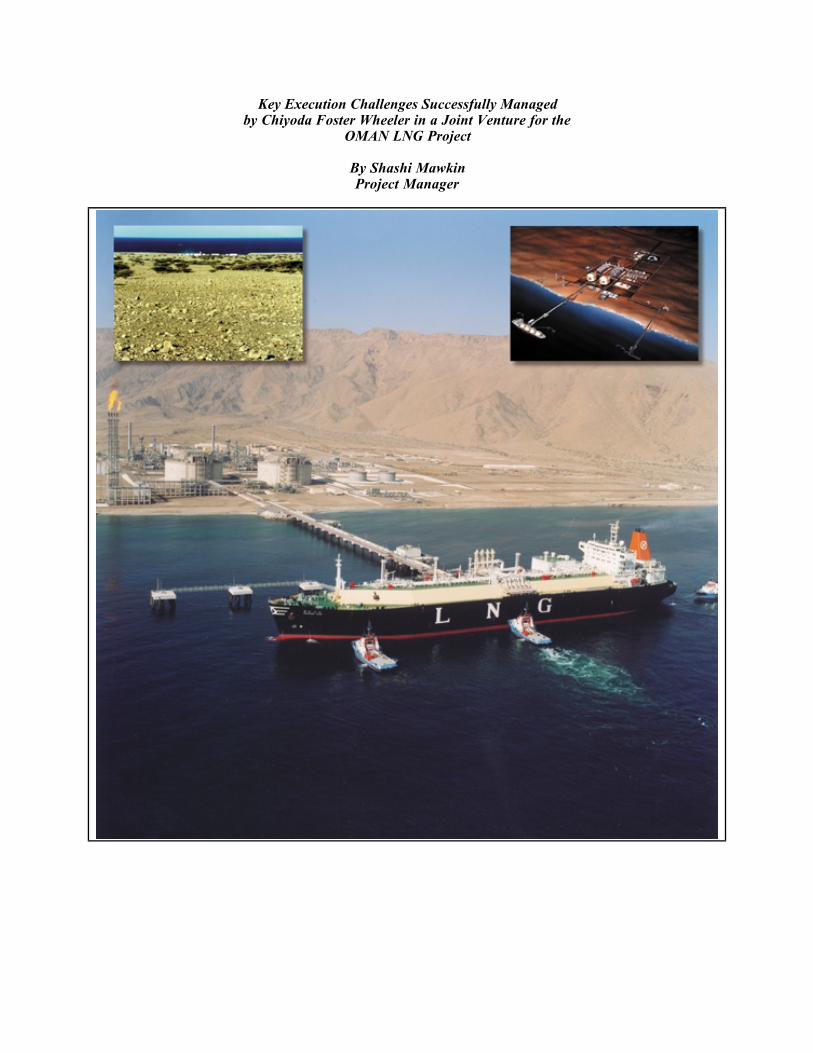
Key Execution Challenges Successfully Managedby Chiyoda Foster Wheeler in a Joint Venture for the
OMAN LNG Project
By Shashi MawkinProject Manager

Mawkin 1
OMAN LNG Project — Key Execution Challenges Successfully Managed by Chiyoda Foster Wheelerin a Joint Venture for the OMAN LNG Project
In the summer of 1996, at a remote site in Oman, telephone communications were not possible.Forty two months later the Oman LNG downstream Project, at an overall cost of more than US$2˚billion, has commenced commercial production of LNG on target.
1. Introduction
Following the discovery of substantial quantities of gas in the Andam and Miqrat formations in
central OMAN during the 1989-1991 period, the OMAN LNG Project has established itself as the
largest Project in the Sultanate of OMAN and a significant new source of Liquefied Natural Gas for
the world s rapidly growing natural gas market.
OMAN LNG L.L.C. (OLNG) was set-up by Royal Decree to handle the Downstream Project to cover
gas liquefaction, transportation and sales of LNG. The share holders of the OMAN LNG Company
are:
Government of OMAN: 51%
Shell: 30%
Total: 5.54%
Partex: 2%
Mitsubishi: 2.77%
Mitsui: 2.77%
Itochu: 0.92%
KOLNG (a Korean Consortium): 5%
Chiyoda-Foster Wheeler (CFW) was awarded a lump-sum contract in 1996 to build one of the largest
and most technologically advanced two-train LNG plant (2 x 3.3 mtpa) on a green field site.
The first LNG train along with utilities and offsites were completed within 38 months and were
handed over to the OLNG in December 1999. The second train was handed over in April 2000, 41.5
months after contract award. The plant is now producing LNG for shipping to Korea and, in the near
future, to Japan, India and other countries.
With a capacity of 6.6 million metric tons of LNG production per year, the Project will add
substantially to the revenue of the Sultanate of Oman, contributing about 10% to the current GDP of
the country. Reputed to be one of the fastest LNG projects ever built, it also ranks as one of the
lowest-cost LNG producers in the world.
Detailed design, engineering, procurement, construction, commissioning and start-up activities have
faced numerous challenges, which have been successfully managed by CFW to meet the Project
objectives. This paper provides an overview of the key activities completed during the Project
development.

Mawkin 2
2. Oman LNG Project Overview
Figure 1
The OMAN LNG plant is located near a natural harbour at Qalhat on the North East Coast of
Oman some 15 km North East of the town of Sur and approx. 350 km by road from the capital,
Muscat (see Fig. 1). This site is naturally well protected from severe ocean currents and tropical
storms and has deep water with close proximity to the shoreline, the LNG jetty needing to be less
that 500 meters long. The attributes of the location not only contribute to the economics of the
Project but also enhance the reliability and safety of the LNG supply chain. Being close to the town
of Sur, there is also a commercial infrastructure on which to base the Project and the services it
requires.

Mawkin 3
Fig. 2 shows the plot plan for the complex comprising two LNG trains, two LNG tanks, each with a
capacity of 120,000 m3, power generation, common facilities area for the inert gas system,
desalination plant, drinking, service and process water system, fire water supply and instrument and
tool air systems; two condensate storage tanks, vapour and liquid flare systems, effluent treatment
plant, water intake and outfall lines, material off-loading and LNG loading jetties. The plot plan
takes into consideration expansion for further three trains.
Figure 2.
The complex receives feed gas collected from the gas fields in central Oman. After necessary
processing in the upstream gathering and processing facilities, the gas is transported via a single feed
gas transmission system to the LNG complex at Qalhat. The feed gas is high quality with low inerts
(around 1% C02) and only a trace quantity of H2S
Design Philosophy
The design of the complex for a 25 years operating life is based on the following principles:
a) Propane pre-cooled \ MR cycle with Air Products and Chemicals Inc. (APCI) main
cryogenic heat exchangers for the liquefaction trains.
b) Shell International Oil Products B.V. technology for the acid gas removal unit.
c) Compressor mechanical drives by fixed speed gas turbines (GE Frame 6 for propane
and GE Frame 7 for Mixed Refrigerant) with variable speed electric starter/helper
motors (7.5MW) for each machine.
d) Once-through sea water main process cooling system.

Mawkin 4
3. Description Of The LNG Plant
The LNG Complex comprises process units, utility plant and offsites required for the production
and shipment of LNG. The total plant concept, including liquefaction was developed by Shell
Global Solutions International B.V. This plant has the largest capacity LNG trains and lowest
emissions in the base load LNG world.
The complex is supplied with dry natural gas which arrives via a single gas feed line. The
incoming gas is filtered and metered before passing to two parallel LNG production trains. Each
identical LNG train comprises treating units for the removal of carbon dioxide, water and mercury,
a liquefaction unit with nitrogen rejection and finally a fractionation unit for the separation of
heavy components and the production of refrigerant make-up and condensate product. The block
diagram is shown in Fig. 3.
Figure 3
Process Units
The Acid Gas Removal unit utilises the Shell Sulfinol D process to achieve the removal of carbon
dioxide and traces of hydrogen sulphide. Offgas from the regenerator is incinerated in the heat
transfer fluid furnace.
The Dehydration unit utilises conventional molecular sieve beds to dry the natural gas feedstock
prior to liquefaction. The final pre-treatment step is mercury removal by passage through a
sulphur impregnated activated carbon bed.
The Liquefaction section utilises APCI s propane-precooled Mixed Refrigerant (MR) process. The
treated gas is first chilled and passed to the Scrub Column where heavy hydrocarbons are removed

Mawkin 5
and passed to the Fractionation section. The chilled gas is then liquefied in APCI s Main Cryogenic
Heat Exchanger before passing to the LNG Stripper for nitrogen rejection.
The APCI process uses two refrigeration loops. The propane loop uses a four stage single casing
compressor driven by a frame 6 gas turbine and helper motor. The MR loop uses a two stage
compressor driven by a frame 7 gas turbine with helper motor. Hydraulic turbines are installed in
the heavy MR circuit and the LNG end flash system. The Liquefaction process flow diagram is
illustrated in Fig. 4.
Figure 4
The Fractionation unit utilises four columns to recover refrigerant grade ethane and propane, and
to produce a stabilised condensate product for export. Liquid NGLs not required for refrigerant
make-up are re-injected.
Offsite Systems
LNG Storage and Loading facilities comprise two full containment LNG storage tanks (120,000 m3
net pumpable each) and eight loading pumps capable of loading a ship at a rate of 10,000 m3/h via
two liquid loading arms and one vapour return arm.
The Condensate Storage and Loading system stores condensate product prior to transfer to marine
tankers. Two floating roof condensate storage tanks are installed which provide approximately 20
days capacity at maximum production. Condensate product is transferred to marine tankers via a

Mawkin 6
loading arm. Facilities are provided to enable stored condensate product to be circulated via a
cooler to maintain the True Vapour Pressure (TVP) specification.
Utility Systems
Heat Transfer Fluid (HTF) systems are provided to supply heat to the LNG trains and process
heaters. Separate systems are installed for each train. A fired heater is used to supply the heat
input to each loop.
A once-through Sea Water Cooling system provides the primary cooling medium for the LNG
trains and the utility systems. Sea water enters via two subsea intake lines before passing through
static and rotating screening equipment. A total of five circulation pumps are provided, two
serving each train plus one spare. Each pump is rated for approximately 16,000 m3/h.
A Tempered Cooling Water System is supplied to provide for machinery cooling within parts of
the complex.
The Fuel Gas system provides fuel to the gas turbine drivers, HTF heaters and regeneration gas
heaters plus other miscellaneous heaters. The collection, mixing and distribution system is designed
to modulate variations in the Wobbe index of HP fuel gas supplied to the gas turbines.
Desalination units provide fresh water for the complex. These supply the Drinking and Process
Water systems, and provide inventory to the fire water system.
Other necessary support facilities include Power Generation (4 off GE Frame 6 gas turbine driven
generators), an Instrument and Tool Air system, an Inert Gas generation and storage system, a
Diesel Fuel system, Fire Fighting systems, Pressure Relief and Liquid Disposal systems and Drainage
and Effluent Treating.
4. Project Set-Up
PROJECT CALENDAR OF EVENTS
Date ActivityMay 96 CFW selected as the preferred Contractor by OLNG.
Nov 96 Main contract award. Management & reporting procedures prepared.
OLNG team mobilised to Reading office.
Order placed for Cryogenic heat exchangers, compression trains and LNG tanks.
Dec 96 Site pioneer force mobilised. Early earthworks and camp facility sub - contracts
awarded. Order placed for Gas Turbine Generators (GTGs)
Apr 97 Home Office manpower stood at 435. 1,500 personnel at site - 1 M site manhours
expended
Aug 97 30% model review completed. Commitment made for 99% equipment and 60%
bulk items. Site achieved 3 M manhours with no LTI (Lost Time Incident).
Ground improvement & detailed Engineering for foundations completed —
milestone #2a achieved
Feb 98 Detailed Engineering 80% Complete. Milestone #3 achieved three months ahead
of plan.
Aug 98 90% Model review completed. Milestone #4 achieved.
Nov 98 Site U/G cabling & piping complete. Milestone #5 achieved.
Jan 00 Pre-commissioning activities commenced for Train 2 and Utility areas.
Apr 99 15 M manhours without LTI achieved. Site Manpower peaked at 6800
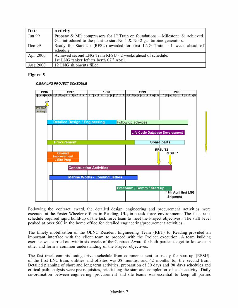
Mawkin 7
Date ActivityJun 99 Propane & MR compressors for 1
st Train on foundations — Milestone 6a achieved.
Gas introduced to the plant to start No 1 & No 2 gas turbine generators.
Dec 99 Ready for Start-Up (RFSU) awarded for first LNG Train - 1 week ahead of
schedule.
Apr 2000 Achieved second LNG Train RFSU - 2 weeks ahead of schedule.
1st LNG tanker left its berth 07th
April.
Aug 2000 12 LNG shipments filled.
Figure 5
OMAN LNG PROJECT SCHEDULE
J J A S O N D J F M A M J J A S O N D J F M A M J J A S O N D J F M A M J J A S O N D J F M A M J J A S O N D
MCA
Detailed Design / Engineering Follow up activities
Life Cycle Database Development
Procurement Spare parts
RFSU T2RFSU T1
Construction Activities
Marine Works - Loading Jetties
Precomm / Comm / Start up *
* 7th April first LNG Shipment
1996 1997 1998 1999 2000
Pre MCAActivity
/ Site Prep
GroundImprovement
Following the contract award, the detailed design, engineering and procurement activities were
executed at the Foster Wheeler offices in Reading, UK, in a task force environment. The fast-track
schedule required rapid build-up of the task force team to meet the Project objectives. The staff level
peaked at over 500 in the home office for detailed engineering/procurement activities.
The timely mobilisation of the OLNG Resident Engineering Team (RET) to Reading provided an
important interface with the client team to proceed with the Project execution. A team building
exercise was carried out within six weeks of the Contract Award for both parties to get to know each
other and form a common understanding of the Project objectives.
The fast track commissioning driven schedule from commencement to ready for start-up (RFSU)
of the first LNG train, utilities and offsites was 38 months, and 42 months for the second train.
Detailed planning of short and long term activities, preparation of 30 days and 90 days schedules and
critical path analysis were pre-requisites, prioritising the start and completion of each activity. Daily
co-ordination between engineering, procurement and site teams was essential to keep all parties
Mawkin 8
informed of tasks in hand, problems and forthcoming activities. It was essential to produce weekly
logs/reports to advise site teams of the progress and shipment status of items of equipment with ETA
dates and engineering progress for discipline activities. This information was critical for the
construction team to plan their weekly activities, including heavy lifting.
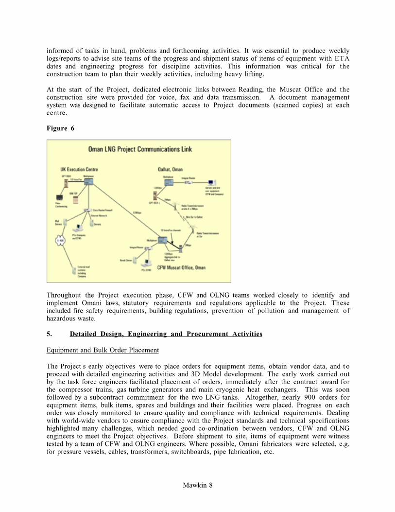
At the start of the Project, dedicated electronic links between Reading, the Muscat Office and the
construction site were provided for voice, fax and data transmission. A document management
system was designed to facilitate automatic access to Project documents (scanned copies) at each
centre.
Figure 6
Throughout the Project execution phase, CFW and OLNG teams worked closely to identify and
implement Omani laws, statutory requirements and regulations applicable to the Project. These
included fire safety requirements, building regulations, prevention of pollution and management of
hazardous waste.
5. Detailed Design, Engineering and Procurement Activities
Equipment and Bulk Order Placement
The Project s early objectives were to place orders for equipment items, obtain vendor data, and t o
proceed with detailed engineering activities and 3D Model development. The early work carried out
by the task force engineers facilitated placement of orders, immediately after the contract award for
the compressor trains, gas turbine generators and main cryogenic heat exchangers. This was soon
followed by a subcontract commitment for the two LNG tanks. Altogether, nearly 900 orders for
equipment items, bulk items, spares and buildings and their facilities were placed. Progress on each
order was closely monitored to ensure quality and compliance with technical requirements. Dealing
with world-wide vendors to ensure compliance with the Project standards and technical specifications
highlighted many challenges, which needed good co-ordination between vendors, CFW and OLNG
engineers to meet the Project objectives. Before shipment to site, items of equipment were witness
tested by a team of CFW and OLNG engineers. Where possible, Omani fabricators were selected, e.g.
for pressure vessels, cables, transformers, switchboards, pipe fabrication, etc.

Mawkin 9
The requirement to provide data for approximately 20 000 spare parts for future plant maintenance
was an integral part of the scope of work by CFW. The value of spare parts was in excess of US$ 20
million.
For this grassroots Project, CFW scope of work also included supply and installation of all
laboratory, workshop, canteen and IT equipment. Other procurement items included a fire engine, an
ambulance, general purpose vehicles, cranes and fork lift trucks.
Material Control
Effective material control was the cornerstone of the successful management and usage of materials.
Foster Wheeler s latest version of its System for Material Inventory and Logistics Evaluation
(SMILE 2000) was used to provide the required control of materials.
The system provided the necessary visibility for all materials but most importantly the many
thousands of bulk material line items, from definition by Engineering through Purchasing and into
Construction. It also maintained strict account of quantities required, purchased, received, held in
stock, allocated and issued, together with the required location of each item by line or drawing.
Flexibility in fabrication and erection was maintained through matching and forecast matching to the
benefit of the overall construction programme.
Figure 7
Shipping
Careful attention was given to the preplanning and subsequent execution of the shipping activities. In
excess of 1800 individual shipments of permanent plant materials were made including the part
charter of 29 heavy lift shipments. Antanov and Illushin transport aircraft were used to ship delicate
control equipment to Muscat. These cargoes were then moved to site using air ride vehicles.

Mawkin 10
A laydown area at Muscat Port was used to temporarily store the large numbers of out of gauge and
heavy cargoes prior to onward shipment to site. A temporary Roll On Roll Off jetty was constructed
at site to allow the delivery of the large cargoes in accordance with site construction requirements.
Detailed Design and Engineering Activities
The execution of detailed design and engineering activities faced many speciality tasks and challenges
throughout the Project development. The task force s sound knowledge, experience and continuing
support by OLNG s resident team played an important part in keeping the Project on schedule.
The 3D model was used as the core spatial design environment for all disciplines. Bills of Materials
(BOMs) were produced which directly integrated with the engineering module of Foster Wheeler s
material control system.
Piping, vessels, LNG tanks, all equipment items, structural steel, foundations and underground pits
were all modelled, as were underground services such as drains, drain hubs and manholes. Cable trays
and trenches were also modelled; the spatial reference database was used to produce automated cable
and drum schedules. All field located instrument and electrical components were located in the 3D
model. The 3D Model data files were electronically transferred to the steel fabricator and site for
plant construction.
At the start of the Project, a full time engineer was appointed to co-ordinate ergonomic studies for
the plant to cover safety, operational and maintenance requirements.
The development of the 3D model also included vendor packages. Some vendors performed their
own 3D modelling exercise, which on completion at vendor works was integrated into the overall
plant model. The benefits of using a 3D model included the possibility of checking automated design
consistency (e.g. clashes), accurate material take-off and construction drawings production, e.g.
isometrics and general arrangement drawings.
Figure 8

Mawkin 11
Formal model reviews at 30%, 60% and 90% completion of the model were held to review the plant
design from safety, ergonomics, maintenance and operational viewpoints. These model review
sessions, which lasted 2 - 4 weeks each, were attended by CFW and OLNG teams. OLNG
representatives included members of the resident team, specialised engineers and operational staff,
who brought to the table their extensive knowledge and experience of LNG plant operation.
Corrective actions taken during these model reviews were very beneficial in minimising recycle during
the construction phase.
The effort provided for 3D model development contributed significantly to timely completion of
construction activities.
Technology Transfer to Omani Nationals
During Project execution, considerable effort was made by both OLNG and CFW teams to ensure
that the technology being used to build and operate the plant was transferred to Oman. A key part of
this technology transfer was the training of Omanis with a view to building a core of competent local
staff capable of operating the plant over its 25 year life. By start-up, more than 50% of the
workforce were Omani nationals.

Mawkin 12
Figure 9
Process Control and Monitoring Systems Total Integration Test
Process control and monitoring systems comprising the DCS, Fire and Gas System, Plant Shut Down
System, Compressor Train Control Systems, Equipment Condition and Monitoring system (CPM),
and other major equipment control panels, were brought to the DCS supplier factory to stage a total
system integration test prior to shipment of equipment to site. This exercise involved over 160
system cabinets, 30 consoles and screens, and included full integration of 17 different types of
subsystems into the main DCS. The logistics achievement of getting all this equipment to site on the
basis of just in time completion with the support of the subsystem vendors was quite remarkable and
required the chartering of an Antonov cargo plane for delivery to Muscat. The attention given t o
detailed upfront planning and vigorous expediting had proved worthwhile.

Mawkin 13
Operator Training System (OTS)
To meet the Project requirements, an order was placed with Honeywell Hi-Spec Solutions for the
development of the Operator Training Simulator (OTS), which combined a dynamic model of the
LNG process with a replica of the control and shutdown systems. The system is a comprehensive
training tool designed to provide intensive hands-on experience for operators on a simulation model
to represent the specific units at their Liquefied Natural Gas (LNG) facility. The benefits from the
OTS include faster start-ups, improved response to abnormal conditions, and a better understanding
of plant behaviour. Following complete factory testing of the system with the OLNG team, the
system was sent to site for operator training purposes.
Management of Compressor Train Order
Timely deliveries to site of power generation equipment and the main compressor train were critical
success factors. To achieve this task, a full time Project Manager, well qualified and experienced, was
assigned to the vendor works. He was supported by two full-time inspectors supplemented by regular
discipline reviews and additional short term residences for such tasks as detailed engineering
development, document reviews and factory testing of these large compressor trains.
The thermodynamic design for a LNG propane compressor is very difficult due to many
constraints. It is a large compressor with side streams. Each stage has performance tolerances
which is similar to individual compressors all within the same casing at a fixed speed. The mass of
gas available for compression at the side streams is dependent on the side stream pressures. The
compressor performance has therefore to be within acceptable tolerances at the side streams as well
as at the compressor discharge.
These stringent performance requirements together with fixed speed of operation of the gas turbine
driver requires accurate prediction of thermodynamic design. This is particularly difficult in the
mixing of the side streams with the main compressor flow where inaccurate assessment of associated
losses can affect the individual stage performance.
To ensure that the specified performance is achieved, a shop performance test is required.
The first performance test of the Oman propane compressor identified deficiencies in meeting the
stringent performance requirements due to higher than expected static component losses in side
streams volute & channel and in the final discharge section. Modifications to the compressor
internals which were verified by Computerised Fluid Dynamics analysis and model testing resulted in
an acceptable performance to achieve the overall LNG plant throughput.
Careful re-planning of all critical paths due to a delay in arrival of compressors at Site, helped t o
minimise construction delays. Propane and MR Compressors on their foundations Milestone for the
First Train was achieved in June 99, as planned, and for the Second Train in July 99.
Main Cryogenic Heat Exchanger (MCHE)
One of the largest cryogenic heat exchangers with capacity of 3.3 MTPA was manufactured by APCI
for the Oman LNG Project.
The delivery, on time, of the two MCHEs was another critical path activity. An excellent
understanding was achieved between APCI and CFW, which resulted in one of the best order
performances.

Mawkin 14
APCI specialists provided their full support at site, right through from the arrival of the heat
exchangers at site to the completion of performance tests for both trains.
Chained Heat Exchangers
Large kettle type heat exchangers "chained" together (tubesheet to tubesheet) are used for pre-
cooling of the treated gas by propane, upstream of the scrub column and the Main Cryogenic Heat
Exchanger. This arrangement minimises the pressure loss and therefore reduces the compressor
power requirement in the refrigeration circuit. Another consequence of this arrangement is the
reduction of interconnecting pipework with obvious advantages of reduced piping costs, plot size, and
reduced number of flanged joints. Such large exchangers with shell diameters approaching 5 metres
and tube lengths up to 16 metres, particularly when chained together, represent a considerable
engineering challenge. The numerous potential problem areas in design, fabrication, testing,
transport, installation, and maintainability of these exchangers were addressed and successfully solved
by CFW for this Project.
Printed Circuit Heat Exchangers
Proprietary heat exchangers of the type known as "Printed Circuit" are used in LNG Stripper
Reboiler and Light MR/End Flash Gas services. This type of heat exchanger provides improved
mechanical integrity and cost effectiveness over other types of heat exchanger previously used in
LNG plants. Detailed study into the performance and reliability of these items for a 25 year life was
undertaken by CFW in conjunction with OLNG and the manufacturer. Finite Element Analyses were
performed by CFW and the vendor as part of these studies. Fig 9(b) shows FEA analysis.
Fig 9(a) Printed Circuit Heat ExchangerFig 9(b) TRESCA Line Contours on the Model Surface

Mawkin 15
Technology Related Issues
LNG plant design of gas liquefaction at —160¡C brings many interesting challenges for the technology
group to handle. For this Project, a very wide range of technology related issues were addressed.
These included material selection and corrosion protection philosophy, design philosophy for
cathodic protection, materials standards and applications for low temperature applications (LTCS,
3_% Ni, 9% Ni and SS), LNG tank material specifications, painting and insulation, design of
cryogenic cold supports, noise control, pneumatic testing specification and acoustic fatigue
assessment.
Task force engineers carried out a number of Finite Element Analyses (FEA). The majority of
applications involved stress analysis associated with pressure vessels, heat exchangers, piping
components, and sea water intake and outfall structures.
During insulation design/selection for the cryogenic duty, main process considerations were
prevention of surface condensation, cold conservation, reduction of heat gain and minimisation of
boil-off. Additional factors included acoustic control and personnel protection.
The design also took account of practical aspects such as piping arrangements, nozzle stand-offs,
structural supports and ease of application. Site insulation strategy required consideration with regard
to pre-insulation and prevention of damage to installed systems. Completed insulation systems had t o
remain functional to ensure that materials remain sound, dry and effective.
6. Computer Management System
The following electronic as-built deliverables were produced by CFW for handover to OLNG, each
covering the entire plant complex.
• Life Cycle Data Base
The Life Cycle Database (PACER) was populated by CFW to meet future operational and
maintenance needs for the Project.
A special team of OLNG and CFW engineers was responsible for the development of over
1,000,000 records for the following three modules of PACER, which is the computerised
operations and maintenance management system selected by Oman LNG.
Document Module: Project deliverables in native, scanned and hard copy format. The
scope covered electronic Handover of more than 30,000 documents.
Maintenance Module: Data Record Cards for static and rotating equipment, electrical,
telecommunication systems and piping items. Altogether, data for over 10,000 cards was
populated to complete this activity. Instrument database (INtools) was linked by OLNG t o
provide selected data to this module to meet the future maintenance requirements.
Warehouse Module: Data for over 20,000 spare parts for equipment supplied for the
Project. All spare parts supplied were coded with Materials and Equipment Standards and Code
(MESC). Spare parts interchangeability was an important part of this activity to minimise
stock levels.
The PACER system enables the plant staff to access all documents for operational and
maintenance needs from desktop computers. An essential aspect of preparing the PACER
data was to ensure absolute consistency of the data which originated from different sources

Mawkin 16
including vendors, licensors and subcontractors as well as CFW. This was a large part of the
data preparation done by CFW.
• 2D Plant Model — Intelligent plant schematics, including process flow diagrams, engineering flow
diagrams, process safeguarding diagrams and material selection diagrams.
• 3D Plant Model — fully detailed intelligent electronic plant model.
• Instrument Database — supplied using INtools software.
• Engineering Database — plant equipment data supplied in integrated, neutral format according t o
ISO 10303-221 (STEP) principles.
7. Total Quality Management
The Total Quality Management programme, identified at the start of the Project, required
completion of more than 150 audits during the detailed engineering, procurement, construction and
commissioning phases of the Project to ensure compliance with Project execution procedures.
More than 4,000 inspection visits were made to vendor works to check and maintain high standards
of quality and technical compliance for equipment and bulk items. This required the mobilisation of
190 inspectors world-wide.
8. Oman LNG Project - Financing
The finance for the Project was arranged by Oman LNG on a limited-recourse Project finance basis;
however, they required this financing structure to include the maximum achievable amount of export
credits, with the minimum number of export credit agencies. This was therefore one of their key
criteria in awarding the EPC Contract.
In response to OLNG’s needs, CFW arranged multi-source export credits supported by ECGD (UK),
US-Exim, SACE (Italy) and NCM (Netherlands) within the US$ 2 billion limited-recourse Project
financing. In order to maximise the export credit coverage, Foster Wheeler developed and
implemented a complex contracting structure to access the multi-source finance whilst meeting the
legal and commercial objectives of the Project. The US, Italian and Dutch export credits were
arranged by FW using affiliate companies in those countries as the nominated exporters.
The ECGD facility, for up to US$ 555 million, was their deal of the year ; in addition to using their
Project financing scheme, it also takes advantage of their co-operation agreement with MITI in
Japan to provide one stop shop coverage for UK, Japanese and EU goods and services in a single
package.
The Italian and Dutch export credits also supported an element of third-country goods. With this
flexibility, CFW was able to procure goods and services not only from the four countries providing
the export credits, but from other European countries and from Japan.
CFW worked with Oman LNG, the ECAs and banks to develop the relevant export credit
documentation, and was then responsible for managing the multi-source procurement to ensure that
this complied with the loan provisions for export credit finance.

Mawkin 17
Figure 10
NCM6%
ECGD55%
US EXIM18%
SACE20.89
EXPORT CREDIT AGENCIES USEDFOR THE OMAN PROJECT
9. Construction Activities
Health, Safety and the Environment (HSE)
From the outset, strict, challenging HSE targets were set for the construction phase. The Project
bettered a Lost Time Injury Frequency Rate of 0.4 and a Total reportable case frequency of 4.5, (per
1m manhours). In a single period, over 15 million manhours were recorded without a Lost Time
Incident.
To achieve such goals, it was necessary to instil a culture of awareness and prevention to ensure issues
were addressed in a timely manner. With the majority of the workforce unaccustomed to the high
standards expected on the Project, educational courses of several descriptions were required as
personnel joined the workforce, at the commencement of key activities and in the event of
unacceptable actions.
HSE attention involved significant planning and publication of procedures prior to construction
commencement. Where risks could be eliminated they were designed out of the works, where not,
they were managed under a detailed control plan
Recommendations and requirements of the Environmental Impact Assessment were met or surpassed.
In all respects, emissions and waste from the Project were eliminated or acceptably managed. As
with attention to safety, it was important to ensure all personnel adopted the right attitude from the
outset. Facilities included a fully managed rubbish landfill area and effluent treatment system. Waste
was removed on a daily basis, dust was constantly suppressed and the impact on the local community
was minimised by design and personnel management.
In all forms of HSE efforts, the emphasis was placed on communication and ensuring each person felt
personally responsible for their own safety and the safety of those around them.
Mawkin 18
Temporary Facilities
At peak a total of 6,800 people were employed at the construction site. Over 90% were resident on
the adjacent campsite. Following completion of infrastructure during month 9, the camp was
occupied on a phased basis through the Project. Facilities included various grades of accommodation
units, power, water, effluent treatment and telephone communication, water dispersion, canteens,
shops, bank, medical and fire services, recreational facilities to suit various cultures, security, fuel
station and a helicopter landing pad.
Overall management of the camp was by CFW with individual camp area management within the
overall area by each subcontractor.
Civil Works
The first nine months of the construction phase saw little above ground permanent works
installation. Effectively, the period was allocated to temporary camp and facility construction, site
surface preparation and pressure grouting the substantial cavities within the rock formation below
major structures. Some 33,000m� of grout was required to attain the specified bearing capacity.
Structure design was a mix of steel and concrete. Main piperack units in Trains and offsites were
designed as precast concrete. A fabrication facility was established onsite and a production time
system established. Pre-casting accounted for 4300m� of concrete with a further 55,000m� poured
in-situ for foundations etc. Adopting a simplistic, production line approach to civil works in
accordance with advance detailed planning proved a key factor in ensuring areas were available for
following trades
As final protection, all sloping surfaces were concrete paved, roads were tarmac surfaced and key at-
risk areas adjacent to equipment were concrete paved. In all, up to 100,000m� was paved for vehicle
or pedestrian access.
Heavy Lift & Transportation
Main items of equipment were delivered to Muscat Port by ocean going vessels and transhipped onto
barges for onward transport to a temporary Roll-on - Roll-off jetty at site.
Initial storage and inspection of equipment was performed in an open laydown area adjacent to site
with appropriate preservation measures adopted as necessary to facilitate a site installation
programme requiring a degree of flexibility.
A substantial cranage fleet operated onsite with 14 No tower cranes, a main Gottwald AK912 1200
tonne unit, plus a range of mobile units from 10-400 tonnes capacity.

Mawkin 19
Figure 11
Mechanical
Mechanical equipment was packaged and delivered to site for hook up under the supervision of
service engineers. The majority of packages, including the main rotating equipment such as pumps,
compressors, diesel and gas turbine generators etc., are located within a central Utility area, whilst the
main compressor package is a major component of the process train.
In order to increase economic efficiency, units were broken down into manageable sizes, and where
possible, for shipment by container.
Piping
Greenfield, self-contained LNG plants require impressive pipe quantities to allow for the volume of
cooling seawater circulation and gas transmission. Seawater lines ranged from 32 to 96 diameter
either constructed from GRE or concrete lined carbon steel material. Early installation of the main
underground lines is essential to prevent access restraints throughout the main construction phase.
With piping almost completely fabricated from four materials — GRE, carbon steel, low temperature
carbon steel and stainless steel — training in the management of different materials for the workforce
was not an issue. The main challenges came from volume of work and pipe sizes.
Electrical and Instrumentation
A milestone of great significance was achieved by month 25 with the completion of all underground
services. This included firemains and drainage and to a large extent covered all main cabling. With a
direct buried cableway design, open trench width over extensive lengths severely disrupted access
during early construction. To meet the milestone, early cable design and material delivery, followed
by a concentrated construction effort was essential.
Early delivery and installation of the DCS in the Operations Building was also a major success factor,
allowing tighter control of loop testing from an early stage. A key success feature in the early start
Mawkin 20
up of the DCS was successful completion of a full Factory Acceptance Test , including System
Integration Test, prior to delivery
10. Plant Commissioning and Start-up
The commissioning work commenced immediately at Contract Award and involved planning for site
activities, plus commissioning input to detailed design, engineering, procurement, construction and
preparation of schedule, procedures and manuals.
The Complex was divided into units/areas, each of which was then further divided into systems and
shown on the commissioning schedule. System limits, definitions, equipment lists, descriptions and
colour mark-ups for each system were produced in time to allow input into appropriate subcontract
documentation. Priority was set for Utility Systems to reach RFSU first to support construction and
commissioning activities.
Several Commissioning resources studies were undertaken to identify total and peak demand for
critical items such as fuel, water and electricity. Other studies concentrated on the logistical
requirements to complete critical activities.
Gas was brought in to the site six months prior to RFSU of the first LNG train. The gas was initially
required for firing gas turbines for electricity generation to support the ongoing work.
System Handover Dossiers were prepared and used for Mechanical Completion and RFSU.
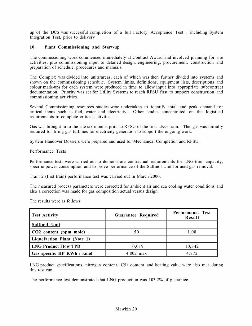
Performance Tests
Performance tests were carried out to demonstrate contractual requirements for LNG train capacity,
specific power consumption and to prove performance of the Sulfinol Unit for acid gas removal.
Train 2 (first train) performance test was carried out in March 2000.
The measured process parameters were corrected for ambient air and sea cooling water conditions and
also a correction was made for gas composition actual versus design.
The results were as follows:
Test Activity Guarantee Required Performance TestResult
Sulfinol Unit
CO2 content (ppm mole) 50 1.08
Liquefaction Plant (Note 1)
LNG Product Flow TPD 10,019 10,342
Gas specific HP KWh / kmol 4.802 max 4.772
LNG product specifications, nitrogen content, C5+ content and heating value were also met during
this test run
The performance test demonstrated that LNG production was 103.2% of guarantee.

Mawkin 21
The total gas HP of the Propane and MR compressors was 98.3% of guaranteed maximum for these
ambient conditions (108.42 MW vs 110.25 MW).
The same test procedure was carried out for Train 1, from 27th to 30th May 2000 and gave the
following results:
Test Activity Guarantee Required Performance TestResult
Sulfinol Unit
CO2 content (ppm mole) 50 0.54
Liquefaction (Note 1)
LNG Production TPD 9,712 10,544
Gas Specific HP KWh / kmol 4.889 4.34
The performance test for Train 1 demonstrated that LNG production was 108.6% of guarantee.
The total gas horsepower of the Propane and MR compressors was 99% of guaranteed maximum for
the ambient conditions, (108.42 MW Vs 109.53 MW).
Note (1) Corrected for prevailing ambient conditions and feed gas composition
Figure 12
11. Conclusion
This paper summarises some of the key challenges experienced and overcome by the CFW and
OLNG teams to complete this Project on schedule. The impressive achievements are the result of
good Project management, planning and teamwork. However, the Oman LNG success story is also
the result of hard work, total commitment, dedication and ownership by a professional team of both
CFW and OLNG staff over the past six years.
12. Acknowledgements
The acceptance of this paper and the valuable contribution by Oman LNG L.L.C. is gratefully
acknowledged. The author also wishes to thank his Project colleagues for their contribution and
support for the writing of this paper.