keynote paper computational modelling of polymer ...membrane.ustc.edu.cn/class/ref/27 computational...
TRANSCRIPT
ARTICLE IN PRESS
0360-5442/$ - se
doi:10.1016/j.en
�Tel.: +1 250
E-mail addr
Energy 32 (2007) 269–280
www.elsevier.com/locate/energy
Keynote Paper
Computational modelling of polymer electrolyte membrane (PEM) fuelcells: Challenges and opportunities
N. Djilali�
University of Victoria, Institute for Integrated Energy Systems & Department of Mechanical, Engineering, Victoria, BC, Canada V8W 3P6
Received 7 November 2005
Abstract
Fuel cells are still undergoing intense development, and the combination of new and optimized materials, improved product
development, novel architectures, more efficient transport processes, and design optimization and integration are expected to lead to
major gains in performance, efficiency, reliability, manufacturability and cost-effectiveness. Computational fuel cell engineering (CFCE)
tools that allow systematic simulation, design and optimization of fuel cell systems would facilitate the integration of such advances,
allow less heavy reliance on hardware prototyping, and reduce development cycles.
CFCE requires the robust integration of models representing a variety of complex multi-physics transport processes characterized by a
broad spectrum of length and time scales. These processes include a fascinating, but not always well understood, array of phenomena
involving fluidic, ionic, electronic and thermal transport in concert with electrochemical reactions. In this paper, we report on some
progress in both fundamental modelling of these phenomena, as well as in the development of integrated, computational fluid dynamics
(CFD) based models for polymer electrolyte membrane (PEM) fuel cells. A new rational model for coupled protonic and water transport
in PEMS, as well direct numerical simulations of two-phase flow in porous gas diffusion electrodes are discussed. Illustrative applications
of CFD-based simulations are presented for conventional fuel cells and novel micro-structured fuel cells. The paper concludes with a
perspective on some of the remaining theoretical, experimental and numerical challenges to achieve truly functional CFCE tools.
r 2006 Elsevier Ltd. All rights reserved.
Keywords: Fuel cell; Transport phenomena; Two phase flow; Modelling; CFD; Polymer electrolyte membranes; Porous electrodes; Computational design;
Micro-fuel cell; Review
1. Introduction
Fuel cells and hydrogen technologies offer a promisingpathway towards sustainable energy systems. They offerthe prospect of low to zero emission power generation forsubWatt to MWatt applications in transportation, heating,manufacturing, and communication. However, many en-gineering and scientific obstacles (as well as economic andsocio-political ones) need to be surmounted before widespread adoption of these technologies becomes possible.
The potential of fuel cells for clean and efficient energyconversion have long been recognized. Fuel cells areadaptable, have a high theoretical efficiency, and, unlikebatteries, they can produce electricity continuously as long
e front matter r 2006 Elsevier Ltd. All rights reserved.
ergy.2006.08.007
721 6034; fax: +1 250 721 6323.
ess: [email protected].
as supplied with a fuel. When fuelled by hydrogen, the onlyby-products of a fuel cell are water and heat. In addition tothe important question surrounding the development of ahydrogen fuelling infrastructure discussed elsewhere [1], themain obstacles to the deployment and commercializationof polymer electrolyte membrane fuel cells (PEMFCs) arecost, durability, and performance [2]. In this paper we willfocus on the role of computational tools in addressingsome of the technical challenges in the development ofbetter performance and affordable PEMFC technology,the lead contender for replacing the ubiquitous battery andinternal combustion engine.The overall operating principle of a PEMFC is relatively
simple. Hydrogen is fed to the cell and oxidized at theanode, while oxygen, usually carried in an air feed stream,is reduced at the cathode. The protons produced at theanode are conducted through the polymer electrolyte
ARTICLE IN PRESS
Nomenclature
c molar concentrationI, i current; current densityk permeabilityF Faraday’s constantNp protonic fluxNl water fluxP pressure
_S source terms saturationT Temperatureu velocitye porosityF potentialm viscosityr densitys conductivity; interfacial tension
N. Djilali / Energy 32 (2007) 269–280270
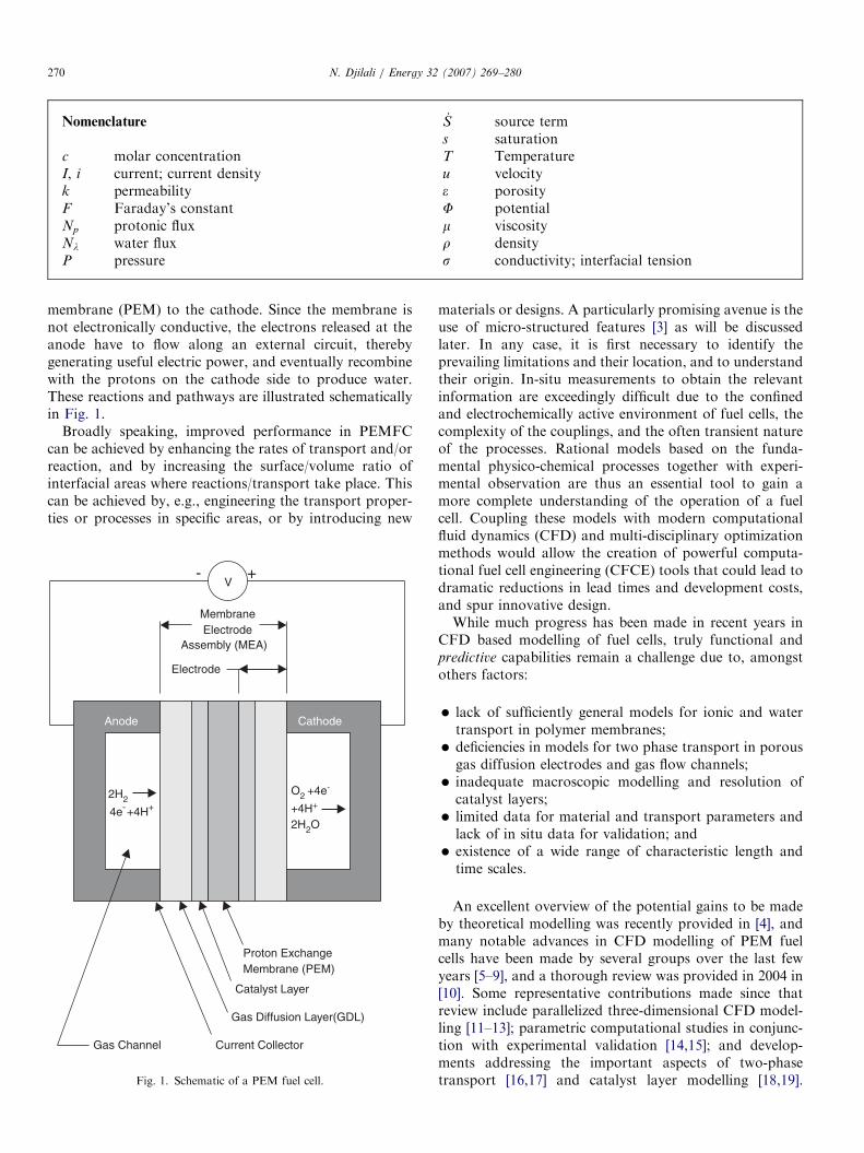
membrane (PEM) to the cathode. Since the membrane isnot electronically conductive, the electrons released at theanode have to flow along an external circuit, therebygenerating useful electric power, and eventually recombinewith the protons on the cathode side to produce water.These reactions and pathways are illustrated schematicallyin Fig. 1.
Broadly speaking, improved performance in PEMFCcan be achieved by enhancing the rates of transport and/orreaction, and by increasing the surface/volume ratio ofinterfacial areas where reactions/transport take place. Thiscan be achieved by, e.g., engineering the transport proper-ties or processes in specific areas, or by introducing new
2H2
4e-+4H+
O2 +4e-
+4H+
2H2O
CathodeAnode
Electrode
MembraneElectrode
Assembly (MEA)
Catalyst Layer
Proton ExchangeMembrane (PEM)
Gas Diffusion Layer(GDL)
V+-
Current CollectorGas Channel
Fig. 1. Schematic of a PEM fuel cell.
materials or designs. A particularly promising avenue is theuse of micro-structured features [3] as will be discussedlater. In any case, it is first necessary to identify theprevailing limitations and their location, and to understandtheir origin. In-situ measurements to obtain the relevantinformation are exceedingly difficult due to the confinedand electrochemically active environment of fuel cells, thecomplexity of the couplings, and the often transient natureof the processes. Rational models based on the funda-mental physico-chemical processes together with experi-mental observation are thus an essential tool to gain amore complete understanding of the operation of a fuelcell. Coupling these models with modern computationalfluid dynamics (CFD) and multi-disciplinary optimizationmethods would allow the creation of powerful computa-tional fuel cell engineering (CFCE) tools that could lead todramatic reductions in lead times and development costs,and spur innovative design.While much progress has been made in recent years in
CFD based modelling of fuel cells, truly functional andpredictive capabilities remain a challenge due to, amongstothers factors:
�
lack of sufficiently general models for ionic and watertransport in polymer membranes; � deficiencies in models for two phase transport in porousgas diffusion electrodes and gas flow channels;
� inadequate macroscopic modelling and resolution ofcatalyst layers;
� limited data for material and transport parameters andlack of in situ data for validation; and
� existence of a wide range of characteristic length andtime scales.
An excellent overview of the potential gains to be madeby theoretical modelling was recently provided in [4], andmany notable advances in CFD modelling of PEM fuelcells have been made by several groups over the last fewyears [5–9], and a thorough review was provided in 2004 in[10]. Some representative contributions made since thatreview include parallelized three-dimensional CFD model-ling [11–13]; parametric computational studies in conjunc-tion with experimental validation [14,15]; and develop-ments addressing the important aspects of two-phasetransport [16,17] and catalyst layer modelling [18,19].
ARTICLE IN PRESSN. Djilali / Energy 32 (2007) 269–280 271
A review of challenges and modelling issues in both lowand high temperature fuel cells, with particular attention toheat management, appeared recently [20]. In this paper, weprovide an overview focused primarily on recent progressmade at the University of Victoria in addressing some ofthe key transport phenomena issues and in the develop-ment of CFD based modelling strategies for PEMFCs. Thefirst part of the paper focuses on fundamental modelling ofspecific transport phenomena encountered in componentlayers of the membrane electrode assembly (MEA). In thesecond part, we discuss the integration of some of thesesub-models into multi-dimensional CFD codes and illus-trate their application in plate and frame unit cells as wellas in novel micro-structured designs. The paper closes witha perspective on some of the remaining challenges.
2. Transport phenomena in PEMFCS
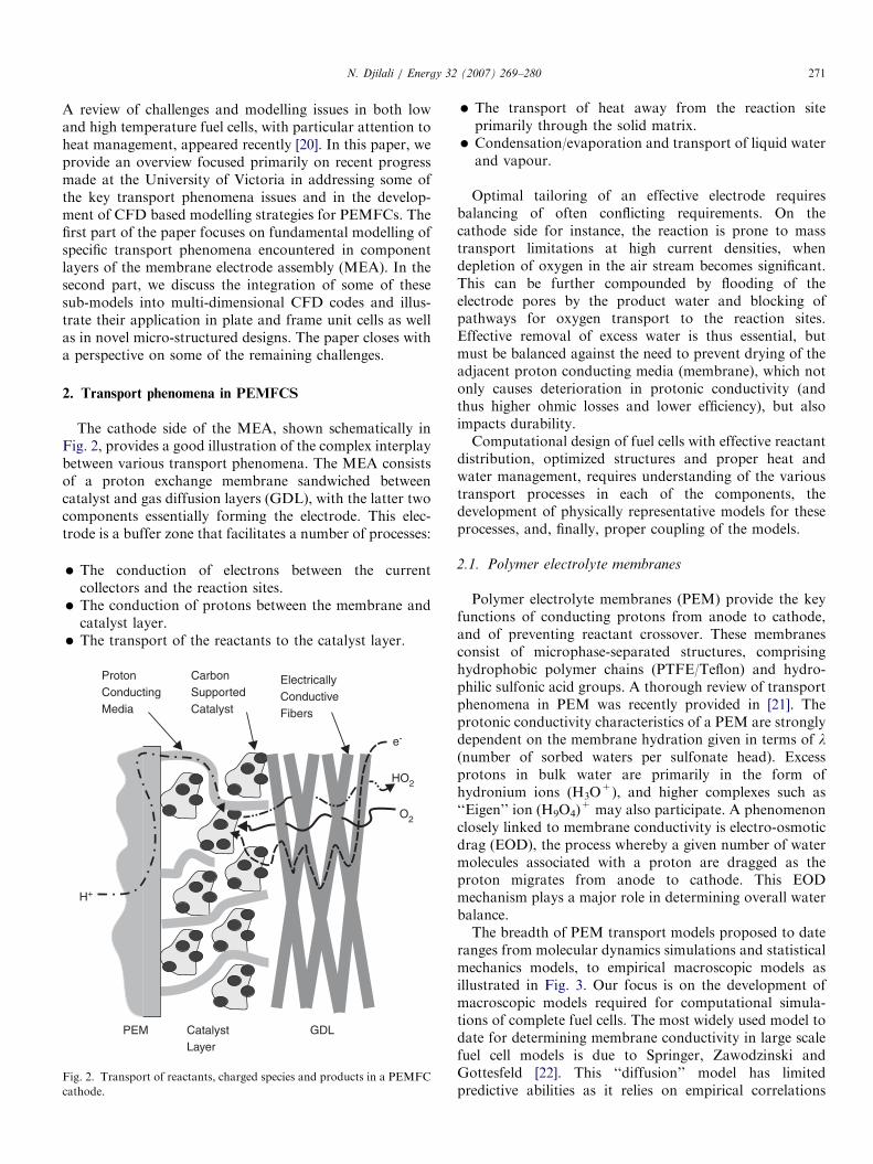
The cathode side of the MEA, shown schematically inFig. 2, provides a good illustration of the complex interplaybetween various transport phenomena. The MEA consistsof a proton exchange membrane sandwiched betweencatalyst and gas diffusion layers (GDL), with the latter twocomponents essentially forming the electrode. This elec-trode is a buffer zone that facilitates a number of processes:
�
Fig
cat
The conduction of electrons between the currentcollectors and the reaction sites.
� The conduction of protons between the membrane andcatalyst layer.
� The transport of the reactants to the catalyst layer.e-
O2
H+
GDLCatalystLayer
PEM
ProtonConductingMedia
CarbonSupportedCatalyst
HO2
ElectricallyConductiveFibers
. 2. Transport of reactants, charged species and products in a PEMFC
hode.
�
The transport of heat away from the reaction siteprimarily through the solid matrix. � Condensation/evaporation and transport of liquid waterand vapour.
Optimal tailoring of an effective electrode requiresbalancing of often conflicting requirements. On thecathode side for instance, the reaction is prone to masstransport limitations at high current densities, whendepletion of oxygen in the air stream becomes significant.This can be further compounded by flooding of theelectrode pores by the product water and blocking ofpathways for oxygen transport to the reaction sites.Effective removal of excess water is thus essential, butmust be balanced against the need to prevent drying of theadjacent proton conducting media (membrane), which notonly causes deterioration in protonic conductivity (andthus higher ohmic losses and lower efficiency), but alsoimpacts durability.Computational design of fuel cells with effective reactant
distribution, optimized structures and proper heat andwater management, requires understanding of the varioustransport processes in each of the components, thedevelopment of physically representative models for theseprocesses, and, finally, proper coupling of the models.
2.1. Polymer electrolyte membranes
Polymer electrolyte membranes (PEM) provide the keyfunctions of conducting protons from anode to cathode,and of preventing reactant crossover. These membranesconsist of microphase-separated structures, comprisinghydrophobic polymer chains (PTFE/Teflon) and hydro-philic sulfonic acid groups. A thorough review of transportphenomena in PEM was recently provided in [21]. Theprotonic conductivity characteristics of a PEM are stronglydependent on the membrane hydration given in terms of l(number of sorbed waters per sulfonate head). Excessprotons in bulk water are primarily in the form ofhydronium ions (H3O
+), and higher complexes such as‘‘Eigen’’ ion (H9O4)
+ may also participate. A phenomenonclosely linked to membrane conductivity is electro-osmoticdrag (EOD), the process whereby a given number of watermolecules associated with a proton are dragged as theproton migrates from anode to cathode. This EODmechanism plays a major role in determining overall waterbalance.The breadth of PEM transport models proposed to date
ranges from molecular dynamics simulations and statisticalmechanics models, to empirical macroscopic models asillustrated in Fig. 3. Our focus is on the development ofmacroscopic models required for computational simula-tions of complete fuel cells. The most widely used model todate for determining membrane conductivity in large scalefuel cell models is due to Springer, Zawodzinski andGottesfeld [22]. This ‘‘diffusion’’ model has limitedpredictive abilities as it relies on empirical correlations
ARTICLE IN PRESS
Fig. 3. Classification of transport models for proton exchange mem-
branes.
0 2 4 6 8 10 12
1
2
3
4
5
6
7
Con
duct
ivity
σ (
S/m
)
Upper bound
Lower bound
ThampanSprin
ger
λ (mol H2O / molSO3-)
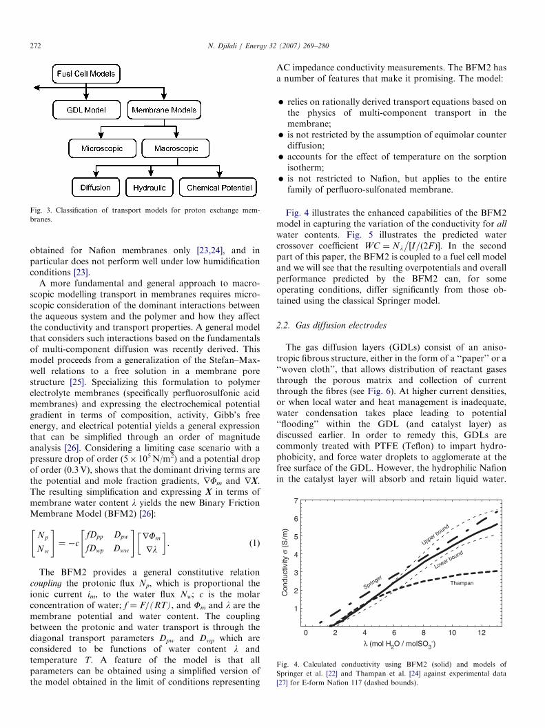
Fig. 4. Calculated conductivity using BFM2 (solid) and models of
Springer et al. [22] and Thampan et al. [24] against experimental data
[27] for E-form Nafion 117 (dashed bounds).
N. Djilali / Energy 32 (2007) 269–280272
obtained for Nafion membranes only [23,24], and inparticular does not perform well under low humidificationconditions [23].
A more fundamental and general approach to macro-scopic modelling transport in membranes requires micro-scopic consideration of the dominant interactions betweenthe aqueous system and the polymer and how they affectthe conductivity and transport properties. A general modelthat considers such interactions based on the fundamentalsof multi-component diffusion was recently derived. Thismodel proceeds from a generalization of the Stefan–Max-well relations to a free solution in a membrane porestructure [25]. Specializing this formulation to polymerelectrolyte membranes (specifically perfluorosulfonic acidmembranes) and expressing the electrochemical potentialgradient in terms of composition, activity, Gibb’s freeenergy, and electrical potential yields a general expressionthat can be simplified through an order of magnitudeanalysis [26]. Considering a limiting case scenario with apressure drop of order (5� 105N/m2) and a potential dropof order (0.3V), shows that the dominant driving terms arethe potential and mole fraction gradients, rFm and rX.The resulting simplification and expressing X in terms ofmembrane water content l yields the new Binary FrictionMembrane Model (BFM2) [26]:
Np
Nw
" #¼ �c
fDpp Dpw
fDwp Dww
" #rFm
rl
� �. (1)
The BFM2 provides a general constitutive relationcoupling the protonic flux Np, which is proportional theionic current im, to the water flux Nw; c is the molarconcentration of water; f ¼ F/(RT), and Fm and l are themembrane potential and water content. The couplingbetween the protonic and water transport is through thediagonal transport parameters Dpw and Dwp which areconsidered to be functions of water content l andtemperature T. A feature of the model is that allparameters can be obtained using a simplified version ofthe model obtained in the limit of conditions representing
AC impedance conductivity measurements. The BFM2 hasa number of features that make it promising. The model:
�
relies on rationally derived transport equations based onthe physics of multi-component transport in themembrane; � is not restricted by the assumption of equimolar counterdiffusion;
� accounts for the effect of temperature on the sorptionisotherm;
� is not restricted to Nafion, but applies to the entirefamily of perfluoro-sulfonated membrane.
Fig. 4 illustrates the enhanced capabilities of the BFM2model in capturing the variation of the conductivity for all
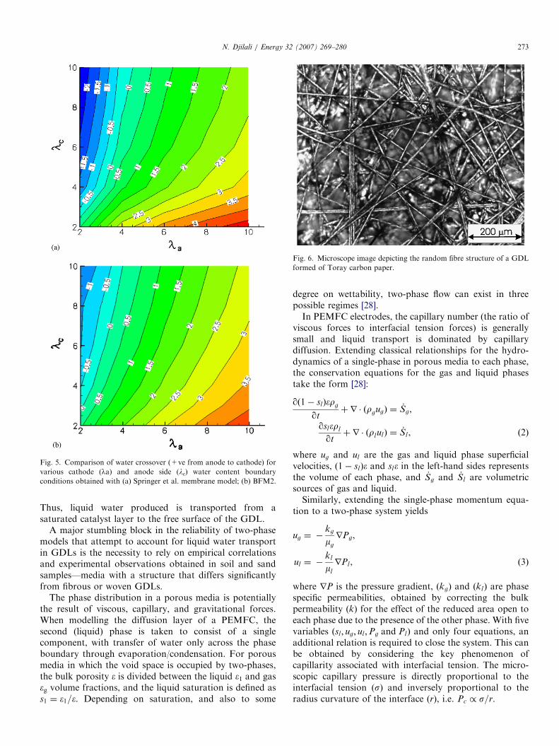
water contents. Fig. 5 illustrates the predicted watercrossover coefficient WC ¼ Nl
�½I=ð2F Þ�. In the second
part of this paper, the BFM2 is coupled to a fuel cell modeland we will see that the resulting overpotentials and overallperformance predicted by the BFM2 can, for someoperating conditions, differ significantly from those ob-tained using the classical Springer model.
2.2. Gas diffusion electrodes
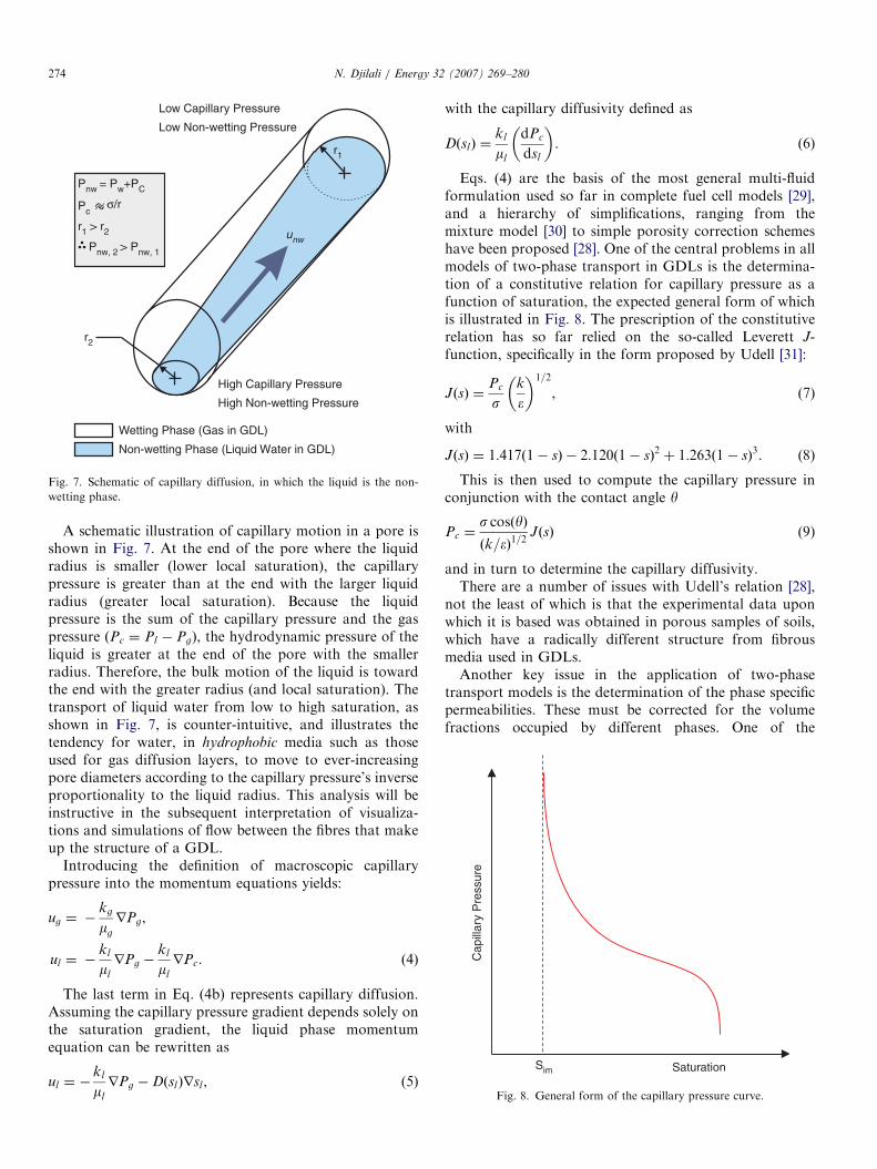
The gas diffusion layers (GDLs) consist of an aniso-tropic fibrous structure, either in the form of a ‘‘paper’’ or a‘‘woven cloth’’, that allows distribution of reactant gasesthrough the porous matrix and collection of currentthrough the fibres (see Fig. 6). At higher current densities,or when local water and heat management is inadequate,water condensation takes place leading to potential‘‘flooding’’ within the GDL (and catalyst layer) asdiscussed earlier. In order to remedy this, GDLs arecommonly treated with PTFE (Teflon) to impart hydro-phobicity, and force water droplets to agglomerate at thefree surface of the GDL. However, the hydrophilic Nafionin the catalyst layer will absorb and retain liquid water.
ARTICLE IN PRESS
Fig. 5. Comparison of water crossover (+ve from anode to cathode) for
various cathode (la) and anode side (lc) water content boundary
conditions obtained with (a) Springer et al. membrane model; (b) BFM2.
Fig. 6. Microscope image depicting the random fibre structure of a GDL
formed of Toray carbon paper.
N. Djilali / Energy 32 (2007) 269–280 273
Thus, liquid water produced is transported from asaturated catalyst layer to the free surface of the GDL.
A major stumbling block in the reliability of two-phasemodels that attempt to account for liquid water transportin GDLs is the necessity to rely on empirical correlationsand experimental observations obtained in soil and sandsamples—media with a structure that differs significantlyfrom fibrous or woven GDLs.
The phase distribution in a porous media is potentiallythe result of viscous, capillary, and gravitational forces.When modelling the diffusion layer of a PEMFC, thesecond (liquid) phase is taken to consist of a singlecomponent, with transfer of water only across the phaseboundary through evaporation/condensation. For porousmedia in which the void space is occupied by two-phases,the bulk porosity e is divided between the liquid e1 and gaseg volume fractions, and the liquid saturation is defined ass1 ¼ �1=�. Depending on saturation, and also to some
degree on wettability, two-phase flow can exist in threepossible regimes [28].In PEMFC electrodes, the capillary number (the ratio of
viscous forces to interfacial tension forces) is generallysmall and liquid transport is dominated by capillarydiffusion. Extending classical relationships for the hydro-dynamics of a single-phase in porous media to each phase,the conservation equations for the gas and liquid phasestake the form [28]:
qð1� slÞ�rg
qtþ r � ðrgugÞ ¼ _Sg,
qsl�rl
qtþ r � ðrlulÞ ¼ _Sl , ð2Þ
where ug and ul are the gas and liquid phase superficialvelocities, ð1� slÞ� and sl� in the left-hand sides representsthe volume of each phase, and _Sg and _Sl are volumetricsources of gas and liquid.Similarly, extending the single-phase momentum equa-
tion to a two-phase system yields
ug ¼ �kg
mg
rPg,
ul ¼ �kl
ml
rPl , ð3Þ
where rP is the pressure gradient, ðkgÞ and ðklÞ are phasespecific permeabilities, obtained by correcting the bulkpermeability (k) for the effect of the reduced area open toeach phase due to the presence of the other phase. With fivevariables ðsl ; ug; ul ;Pg and PlÞ and only four equations, anadditional relation is required to close the system. This canbe obtained by considering the key phenomenon ofcapillarity associated with interfacial tension. The micro-scopic capillary pressure is directly proportional to theinterfacial tension (s) and inversely proportional to theradius curvature of the interface (r), i.e. Pc / s=r.
ARTICLE IN PRESS
High Capillary Pressure
High Non-wetting Pressure
Low Capillary Pressure
Low Non-wetting Pressure
unw
r2
r1
Pnw = Pw+PC
Pc
r1 > r2
Pnw, 2 > Pnw, 1
Wetting Phase (Gas in GDL)
Non-wetting Phase (Liquid Water in GDL)
σ/r
Fig. 7. Schematic of capillary diffusion, in which the liquid is the non-
wetting phase.
Sim
Cap
illar
y P
ress
ure
Saturation
Fig. 8. General form of the capillary pressure curve.
N. Djilali / Energy 32 (2007) 269–280274
A schematic illustration of capillary motion in a pore isshown in Fig. 7. At the end of the pore where the liquidradius is smaller (lower local saturation), the capillarypressure is greater than at the end with the larger liquidradius (greater local saturation). Because the liquidpressure is the sum of the capillary pressure and the gaspressure ðPc ¼ Pl � PgÞ, the hydrodynamic pressure of theliquid is greater at the end of the pore with the smallerradius. Therefore, the bulk motion of the liquid is towardthe end with the greater radius (and local saturation). Thetransport of liquid water from low to high saturation, asshown in Fig. 7, is counter-intuitive, and illustrates thetendency for water, in hydrophobic media such as thoseused for gas diffusion layers, to move to ever-increasingpore diameters according to the capillary pressure’s inverseproportionality to the liquid radius. This analysis will beinstructive in the subsequent interpretation of visualiza-tions and simulations of flow between the fibres that makeup the structure of a GDL.
Introducing the definition of macroscopic capillarypressure into the momentum equations yields:
ug ¼ �kg
mg
rPg,
ul ¼ �kl
ml
rPg �kl
ml
rPc. ð4Þ
The last term in Eq. (4b) represents capillary diffusion.Assuming the capillary pressure gradient depends solely onthe saturation gradient, the liquid phase momentumequation can be rewritten as
ul ¼ �kl
ml
rPg �DðslÞrsl , (5)
with the capillary diffusivity defined as
DðslÞ ¼kl
ml
dPc
dsl
� �. (6)
Eqs. (4) are the basis of the most general multi-fluidformulation used so far in complete fuel cell models [29],and a hierarchy of simplifications, ranging from themixture model [30] to simple porosity correction schemeshave been proposed [28]. One of the central problems in allmodels of two-phase transport in GDLs is the determina-tion of a constitutive relation for capillary pressure as afunction of saturation, the expected general form of whichis illustrated in Fig. 8. The prescription of the constitutiverelation has so far relied on the so-called Leverett J-function, specifically in the form proposed by Udell [31]:
JðsÞ ¼Pc
sk
�
� �1=2
, (7)
with
JðsÞ ¼ 1:417ð1� sÞ � 2:120ð1� sÞ2 þ 1:263ð1� sÞ3. (8)
This is then used to compute the capillary pressure inconjunction with the contact angle y
Pc ¼s cosðyÞ
ðk=�Þ1=2JðsÞ (9)
and in turn to determine the capillary diffusivity.There are a number of issues with Udell’s relation [28],
not the least of which is that the experimental data uponwhich it is based was obtained in porous samples of soils,which have a radically different structure from fibrousmedia used in GDLs.Another key issue in the application of two-phase
transport models is the determination of the phase specificpermeabilities. These must be corrected for the volumefractions occupied by different phases. One of the
ARTICLE IN PRESS
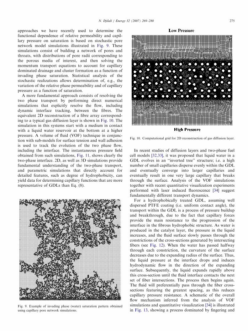
Fig. 10. Computational grid for 2D reconstruction of gas diffusion layer.
N. Djilali / Energy 32 (2007) 269–280 275
approaches we have recently used to determine thefunctional dependence of relative permeability and capil-lary pressure on saturation is based on stochastic porenetwork model simulations illustrated in Fig. 9. Thesesimulations consist of building a network of pores andthroats, with distributions of pore radii corresponding tothe porous media of interest, and then solving themomentum transport equations to account for capillarydominated drainage and cluster formation as a function ofinvading phase saturation. Statistical analysis of thestochastic realizations allows determination of, e.g., thevariation of the relative phase permeability and of capillarypressure as a function of saturation.
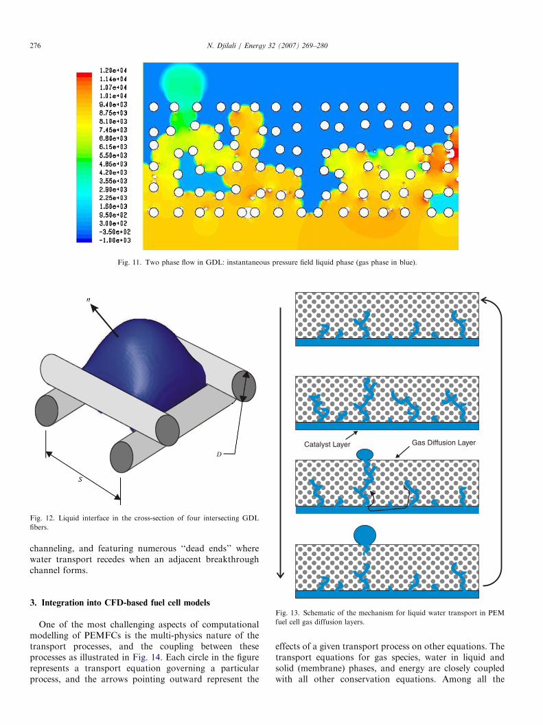
A more fundamental approach consists of resolving thetwo phase transport by performing direct numericalsimulations that explicitly resolve the flow, includingdynamic interface tracking, between the fibres. Theequivalent 2D reconstruction of a fibre array correspond-ing to a typical gas diffusion layer is shown in Fig. 10. Thesimulation in this systems start with a medium in contactwith a liquid water reservoir at the bottom at a higherpressure. A volume of fluid (VOF) technique in conjunc-tion with sub-models for surface tension and wall adhesionis used to track the evolution of the two phase flow,including the interface. The instantaneous pressure fieldobtained from such simulations, Fig. 11, shows clearly thetwo-phase interface. 2D, as well as 3D simulations providefundamental understanding of the two-phase transport,and parametric simulations that directly account fordetailed features, such as degree of hydrophobicity, canyield data for determining capillary functions that are morerepresentative of GDLs than Eq. (8).
Fig. 9. Example of invading phase (water) saturation pattern obtained
using capillary pore network simulations.
In recent studies of diffusion layers and two-phase fuelcell models [32,33], it was proposed that liquid water in aGDL evolves in an ‘‘inverted tree’’ structure; i.e. a highnumber of small capillaries disperse evenly within the GDLand eventually converge into larger capillaries andeventually result in one very large capillary that breaksthrough the surface. Analysis of the VOF simulationstogether with recent quantitative visualization experimentsperformed with laser induced fluorescence [34] suggestfundamentally different transport dynamics.For a hydrophobically treated GDL, assuming well
dispersed PTFE coating (i.e. uniform contact angle), thetransport within the GDL is a process of pressure buildupand breakthrough, due to the fact that capillary forcesprovide the main resistance to the progression of theinterface in the fibrous hydrophobic structure. As water isproduced in the catalyst layer, the pressure in the liquidincreases, and the fluid surface slowly passes through theconstrictions of the cross-sections generated by intersectingfibers (see Fig. 12). When the water has passed halfwaythrough each constriction, the curvature of the surfacedecreases due to the expanding radius of the surface. Thus,the liquid pressure at the interface drops and induceshydrodynamic flow in the direction of the expandingsurface. Subsequently, the liquid expands rapidly abovethis cross-section until the fluid interface contacts the nextset of fiber intersections. The process then begins again.The fluid will preferentially pass through the fiber cross-sections featuring the greatest spacing, as this reducescapillary pressure resistance. A schematic of the overallflow mechanism inferred from the analysis of VOFsimulations and quantitative visualization [34] is illustratedin Fig. 13, showing a process dominated by fingering and
ARTICLE IN PRESS
Fig. 11. Two phase flow in GDL: instantaneous pressure field liquid phase (gas phase in blue).
Fig. 12. Liquid interface in the cross-section of four intersecting GDL
fibers.
Catalyst Layer Gas Diffusion Layer
N. Djilali / Energy 32 (2007) 269–280276
channeling, and featuring numerous ‘‘dead ends’’ wherewater transport recedes when an adjacent breakthroughchannel forms.
Fig. 13. Schematic of the mechanism for liquid water transport in PEM
fuel cell gas diffusion layers.
3. Integration into CFD-based fuel cell models
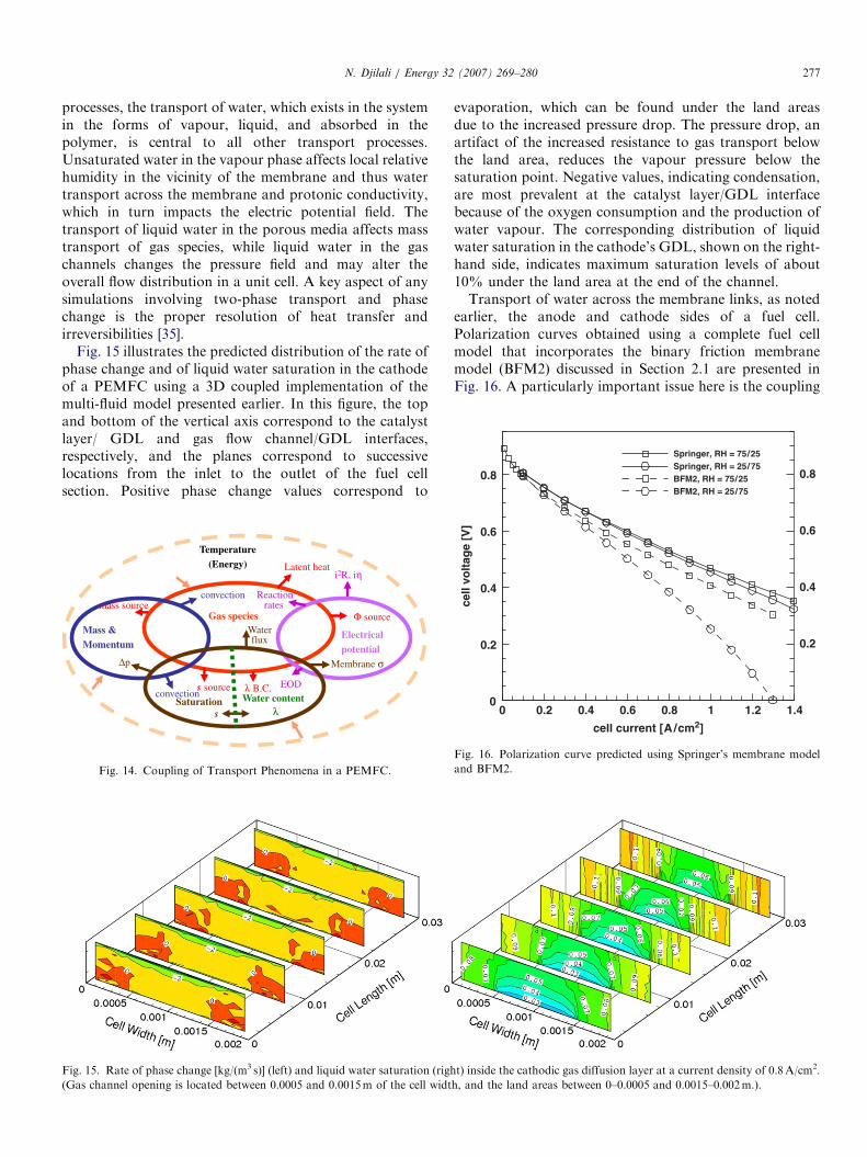
One of the most challenging aspects of computationalmodelling of PEMFCs is the multi-physics nature of thetransport processes, and the coupling between theseprocesses as illustrated in Fig. 14. Each circle in the figurerepresents a transport equation governing a particularprocess, and the arrows pointing outward represent the
effects of a given transport process on other equations. Thetransport equations for gas species, water in liquid andsolid (membrane) phases, and energy are closely coupledwith all other conservation equations. Among all the
ARTICLE IN PRESS
0.8 0.8
Springer, RH = 75/25Springer, RH = 25/75BFM2, RH = 75/25BFM2, RH = 25/75
N. Djilali / Energy 32 (2007) 269–280 277
processes, the transport of water, which exists in the systemin the forms of vapour, liquid, and absorbed in thepolymer, is central to all other transport processes.Unsaturated water in the vapour phase affects local relativehumidity in the vicinity of the membrane and thus watertransport across the membrane and protonic conductivity,which in turn impacts the electric potential field. Thetransport of liquid water in the porous media affects masstransport of gas species, while liquid water in the gaschannels changes the pressure field and may alter theoverall flow distribution in a unit cell. A key aspect of anysimulations involving two-phase transport and phasechange is the proper resolution of heat transfer andirreversibilities [35].
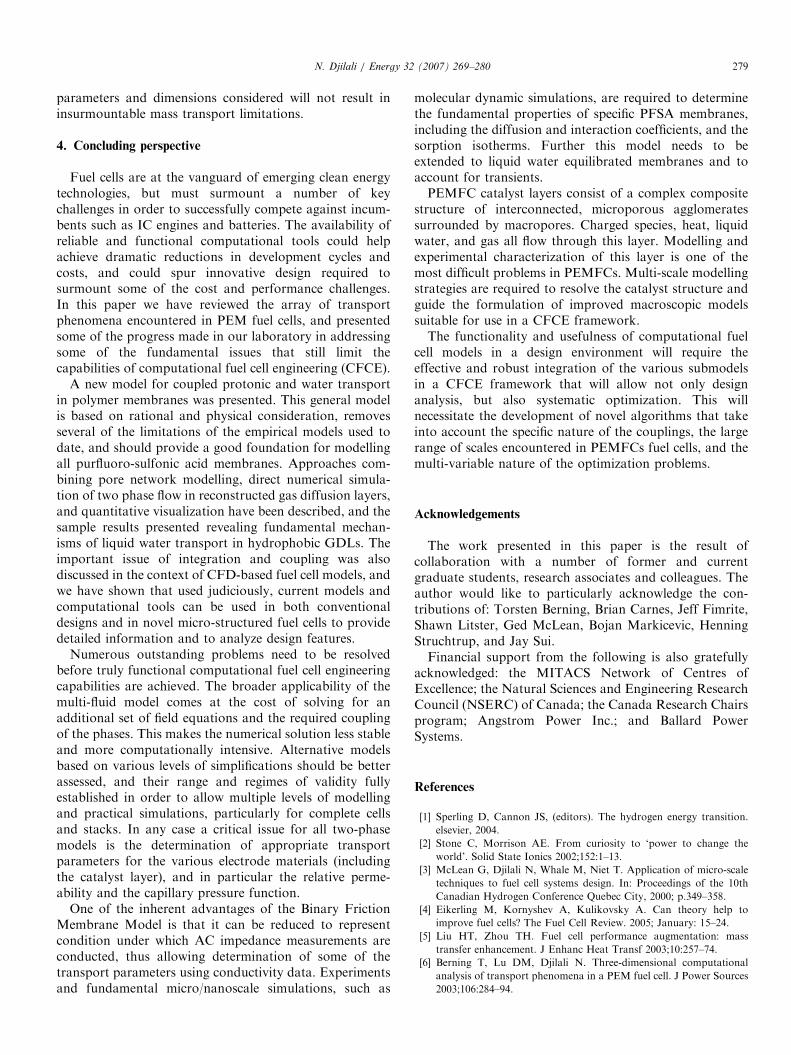
Fig. 15 illustrates the predicted distribution of the rate ofphase change and of liquid water saturation in the cathodeof a PEMFC using a 3D coupled implementation of themulti-fluid model presented earlier. In this figure, the topand bottom of the vertical axis correspond to the catalystlayer/ GDL and gas flow channel/GDL interfaces,respectively, and the planes correspond to successivelocations from the inlet to the outlet of the fuel cellsection. Positive phase change values correspond to
Gas species
Temperature(Energy)
i2R, iηLatent heat
convection
Mass & Momentum
mass source
Electricalpotential
Φ source
Reactionrates
λ B.C.Water content
λSaturation
s
Waterflux
EODconvection
Δp
s source
Membrane σ
Fig. 14. Coupling of Transport Phenomena in a PEMFC.
Fig. 15. Rate of phase change [kg/(m3 s)] (left) and liquid water saturation (righ
(Gas channel opening is located between 0.0005 and 0.0015m of the cell widt
evaporation, which can be found under the land areasdue to the increased pressure drop. The pressure drop, anartifact of the increased resistance to gas transport belowthe land area, reduces the vapour pressure below thesaturation point. Negative values, indicating condensation,are most prevalent at the catalyst layer/GDL interfacebecause of the oxygen consumption and the production ofwater vapour. The corresponding distribution of liquidwater saturation in the cathode’s GDL, shown on the right-hand side, indicates maximum saturation levels of about10% under the land area at the end of the channel.Transport of water across the membrane links, as noted
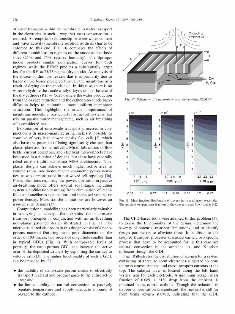
earlier, the anode and cathode sides of a fuel cell.Polarization curves obtained using a complete fuel cellmodel that incorporates the binary friction membranemodel (BFM2) discussed in Section 2.1 are presented inFig. 16. A particularly important issue here is the coupling
t) inside the cathodic gas diffusion layer at a current density of 0.8A/cm2.
h, and the land areas between 0–0.0005 and 0.0015–0.002m.).
cell current [A/cm2]
cell
volt
age
[V]
0 0.2 0.4 0.6 0.8 1.2 1.40
0.2 0.2
0.4 0.4
0.6 0.6
1
Fig. 16. Polarization curve predicted using Springer’s membrane model
and BFM2.
ARTICLE IN PRESS
Fig. 17. Schematic of a micro-structured air-breathing PEMFC.
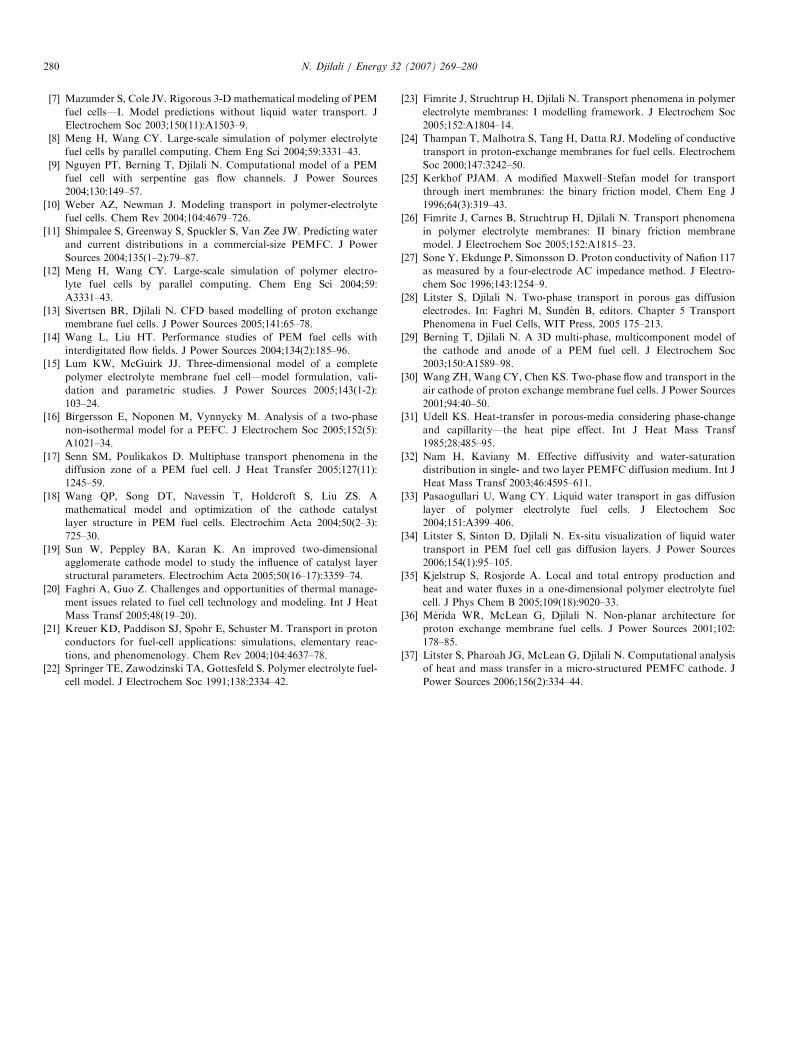
Fig. 18. Mass fraction distribution of oxygen in three adjacent electrodes.
The ambient oxygen mass fraction in the convective air flow (top) is 0.23.
N. Djilali / Energy 32 (2007) 269–280278
of water transport within the membrane to water transportin the electrodes in such a way that mass conservation isensured. An empirical relationship between water contentand water activity (membrane sorption isotherm) has to beenforced to this end. Fig. 16 compares the effects ofdifferent humidification regimes on the anode and cathodesides (25% and 75% relative humidity). The Springermodel predicts similar polarization curves for bothregimes, while the BFM2 predicts a substantially largerloss for the RH ¼ 25/75 regime (dry anode). An analysis ofthe source of this loss reveals that it is primarily due tolarger ohmic losses predicted through the membrane as aresult of drying on the anode side. In this case, there is nowater to hydrate the anode catalyst layer, unlike the case ofthe dry cathode (RH ¼ 75/25), where the water productionfrom the oxygen reduction and the cathode-to-anode back-diffusion helps to maintain a more uniform membranesaturation. This highlights the crucial importance ofmembrane modelling, particularly for fuel cell systems thatrely on passive water management, such as air breathingcells considered next.
Exploitation of microscale transport processes in con-junction with macro-manufacturing makes it possible toconceive of very high power density fuel cells [3], whichalso have the potential of being significantly cheaper thanplanar plate and frame fuel cells. Micro-fabrication of flowfields, current collectors, and electrical interconnects havebeen used in a number of designs, but these have generallyrelied on the traditional planar MEA architecture. Non-planar designs can achieve much higher active area tovolume ratios, and hence higher volumetric power densi-ties, as was demonstrated in our waved cell topology [36].For applications requiring low power, operation in passiveair-breathing mode offers several advantages, includingsystem simplification resulting from elimination of mani-folds and ancillaries such as fans and increased volumetricpower density. Mass transfer limitations are however anissue in such designs [37].
Computational modelling has been particularly valuablein analyzing a concept that exploits the microscaletransport principles in conjunction with an air-breathingnon-planar patented design illustrated in Fig. 17. Themicro-structured electrodes in this design consist of a nano-porous material featuring mean pore diameters on theorder of 100 nm, i.e. two orders of magnitude smaller thanin typical GDLs (Fig. 6). With comparable levels ofporosity, the nano-porous GDL can increase the activearea of the deposited catalyst by exploiting the surface tovolume ratio [3]. The higher functionality of such a GDLcan be impeded by [37]:
�
the inability of nano-scale porous media to effectivelytransport reactant and product gases to the entire activearea; and � the limited ability of natural convection to passivelyregulate temperature and supply adequate amounts ofoxygen to the cathode.
The CFD-based tools were adapted to this problem [37]to assess the functionality of the design, determine theseverity of potential transport limitations, and to identifydesign parameters to alleviate these. In addition to thecoupled transport processes discussed earlier, two specificprocess that have to be accounted for in this case arenatural convection in the ambient air, and Knudsendiffusion though the GDL.Fig. 18 illustrates the distribution of oxygen for a system
consisting of three adjacent electrodes subjected to non-uniform convective heat and mass transport currents at thetop. The catalyst layer is located along the left handvertical axis for each electrode. A minimum oxygen massfraction of 0.089, a 61% drop from the ambient, isobtained in the central cathode. Though the reduction inoxygen concentration is significant, the fuel cell is still farfrom being oxygen starved, indicating that the GDL
ARTICLE IN PRESSN. Djilali / Energy 32 (2007) 269–280 279
parameters and dimensions considered will not result ininsurmountable mass transport limitations.
4. Concluding perspective
Fuel cells are at the vanguard of emerging clean energytechnologies, but must surmount a number of keychallenges in order to successfully compete against incum-bents such as IC engines and batteries. The availability ofreliable and functional computational tools could helpachieve dramatic reductions in development cycles andcosts, and could spur innovative design required tosurmount some of the cost and performance challenges.In this paper we have reviewed the array of transportphenomena encountered in PEM fuel cells, and presentedsome of the progress made in our laboratory in addressingsome of the fundamental issues that still limit thecapabilities of computational fuel cell engineering (CFCE).
A new model for coupled protonic and water transportin polymer membranes was presented. This general modelis based on rational and physical consideration, removesseveral of the limitations of the empirical models used todate, and should provide a good foundation for modellingall purfluoro-sulfonic acid membranes. Approaches com-bining pore network modelling, direct numerical simula-tion of two phase flow in reconstructed gas diffusion layers,and quantitative visualization have been described, and thesample results presented revealing fundamental mechan-isms of liquid water transport in hydrophobic GDLs. Theimportant issue of integration and coupling was alsodiscussed in the context of CFD-based fuel cell models, andwe have shown that used judiciously, current models andcomputational tools can be used in both conventionaldesigns and in novel micro-structured fuel cells to providedetailed information and to analyze design features.
Numerous outstanding problems need to be resolvedbefore truly functional computational fuel cell engineeringcapabilities are achieved. The broader applicability of themulti-fluid model comes at the cost of solving for anadditional set of field equations and the required couplingof the phases. This makes the numerical solution less stableand more computationally intensive. Alternative modelsbased on various levels of simplifications should be betterassessed, and their range and regimes of validity fullyestablished in order to allow multiple levels of modellingand practical simulations, particularly for complete cellsand stacks. In any case a critical issue for all two-phasemodels is the determination of appropriate transportparameters for the various electrode materials (includingthe catalyst layer), and in particular the relative perme-ability and the capillary pressure function.
One of the inherent advantages of the Binary FrictionMembrane Model is that it can be reduced to representcondition under which AC impedance measurements areconducted, thus allowing determination of some of thetransport parameters using conductivity data. Experimentsand fundamental micro/nanoscale simulations, such as
molecular dynamic simulations, are required to determinethe fundamental properties of specific PFSA membranes,including the diffusion and interaction coefficients, and thesorption isotherms. Further this model needs to beextended to liquid water equilibrated membranes and toaccount for transients.PEMFC catalyst layers consist of a complex composite
structure of interconnected, microporous agglomeratessurrounded by macropores. Charged species, heat, liquidwater, and gas all flow through this layer. Modelling andexperimental characterization of this layer is one of themost difficult problems in PEMFCs. Multi-scale modellingstrategies are required to resolve the catalyst structure andguide the formulation of improved macroscopic modelssuitable for use in a CFCE framework.The functionality and usefulness of computational fuel
cell models in a design environment will require theeffective and robust integration of the various submodelsin a CFCE framework that will allow not only designanalysis, but also systematic optimization. This willnecessitate the development of novel algorithms that takeinto account the specific nature of the couplings, the largerange of scales encountered in PEMFCs fuel cells, and themulti-variable nature of the optimization problems.
Acknowledgements
The work presented in this paper is the result ofcollaboration with a number of former and currentgraduate students, research associates and colleagues. Theauthor would like to particularly acknowledge the con-tributions of: Torsten Berning, Brian Carnes, Jeff Fimrite,Shawn Litster, Ged McLean, Bojan Markicevic, HenningStruchtrup, and Jay Sui.Financial support from the following is also gratefully
acknowledged: the MITACS Network of Centres ofExcellence; the Natural Sciences and Engineering ResearchCouncil (NSERC) of Canada; the Canada Research Chairsprogram; Angstrom Power Inc.; and Ballard PowerSystems.
References
[1] Sperling D, Cannon JS, (editors). The hydrogen energy transition.
elsevier, 2004.
[2] Stone C, Morrison AE. From curiosity to ‘power to change the
world’. Solid State Ionics 2002;152:1–13.
[3] McLean G, Djilali N, Whale M, Niet T. Application of micro-scale
techniques to fuel cell systems design. In: Proceedings of the 10th
Canadian Hydrogen Conference Quebec City, 2000; p.349–358.
[4] Eikerling M, Kornyshev A, Kulikovsky A. Can theory help to
improve fuel cells? The Fuel Cell Review. 2005; January: 15–24.
[5] Liu HT, Zhou TH. Fuel cell performance augmentation: mass
transfer enhancement. J Enhanc Heat Transf 2003;10:257–74.
[6] Berning T, Lu DM, Djilali N. Three-dimensional computational
analysis of transport phenomena in a PEM fuel cell. J Power Sources
2003;106:284–94.
ARTICLE IN PRESSN. Djilali / Energy 32 (2007) 269–280280
[7] Mazumder S, Cole JV. Rigorous 3-D mathematical modeling of PEM
fuel cells—I. Model predictions without liquid water transport. J
Electrochem Soc 2003;150(11):A1503–9.
[8] Meng H, Wang CY. Large-scale simulation of polymer electrolyte
fuel cells by parallel computing. Chem Eng Sci 2004;59:3331–43.
[9] Nguyen PT, Berning T, Djilali N. Computational model of a PEM
fuel cell with serpentine gas flow channels. J Power Sources
2004;130:149–57.
[10] Weber AZ, Newman J. Modeling transport in polymer-electrolyte
fuel cells. Chem Rev 2004;104:4679–726.
[11] Shimpalee S, Greenway S, Spuckler S, Van Zee JW. Predicting water
and current distributions in a commercial-size PEMFC. J Power
Sources 2004;135(1–2):79–87.
[12] Meng H, Wang CY. Large-scale simulation of polymer electro-
lyte fuel cells by parallel computing. Chem Eng Sci 2004;59:
A3331–43.
[13] Sivertsen BR, Djilali N. CFD based modelling of proton exchange
membrane fuel cells. J Power Sources 2005;141:65–78.
[14] Wang L, Liu HT. Performance studies of PEM fuel cells with
interdigitated flow fields. J Power Sources 2004;134(2):185–96.
[15] Lum KW, McGuirk JJ. Three-dimensional model of a complete
polymer electrolyte membrane fuel cell—model formulation, vali-
dation and parametric studies. J Power Sources 2005;143(1-2):
103–24.
[16] Birgersson E, Noponen M, Vynnycky M. Analysis of a two-phase
non-isothermal model for a PEFC. J Electrochem Soc 2005;152(5):
A1021–34.
[17] Senn SM, Poulikakos D. Multiphase transport phenomena in the
diffusion zone of a PEM fuel cell. J Heat Transfer 2005;127(11):
1245–59.
[18] Wang QP, Song DT, Navessin T, Holdcroft S, Liu ZS. A
mathematical model and optimization of the cathode catalyst
layer structure in PEM fuel cells. Electrochim Acta 2004;50(2–3):
725–30.
[19] Sun W, Peppley BA, Karan K. An improved two-dimensional
agglomerate cathode model to study the influence of catalyst layer
structural parameters. Electrochim Acta 2005;50(16–17):3359–74.
[20] Faghri A, Guo Z. Challenges and opportunities of thermal manage-
ment issues related to fuel cell technology and modeling. Int J Heat
Mass Transf 2005;48(19–20).
[21] Kreuer KD, Paddison SJ, Spohr E, Schuster M. Transport in proton
conductors for fuel-cell applications: simulations, elementary reac-
tions, and phenomenology. Chem Rev 2004;104:4637–78.
[22] Springer TE, Zawodzinski TA, Gottesfeld S. Polymer electrolyte fuel-
cell model. J Electrochem Soc 1991;138:2334–42.
[23] Fimrite J, Struchtrup H, Djilali N. Transport phenomena in polymer
electrolyte membranes: I modelling framework. J Electrochem Soc
2005;152:A1804–14.
[24] Thampan T, Malhotra S, Tang H, Datta RJ. Modeling of conductive
transport in proton-exchange membranes for fuel cells. Electrochem
Soc 2000;147:3242–50.
[25] Kerkhof PJAM. A modified Maxwell–Stefan model for transport
through inert membranes: the binary friction model. Chem Eng J
1996;64(3):319–43.
[26] Fimrite J, Carnes B, Struchtrup H, Djilali N. Transport phenomena
in polymer electrolyte membranes: II binary friction membrane
model. J Electrochem Soc 2005;152:A1815–23.
[27] Sone Y, Ekdunge P, Simonsson D. Proton conductivity of Nafion 117
as measured by a four-electrode AC impedance method. J Electro-
chem Soc 1996;143:1254–9.
[28] Litster S, Djilali N. Two-phase transport in porous gas diffusion
electrodes. In: Faghri M, Sunden B, editors. Chapter 5 Transport
Phenomena in Fuel Cells, WIT Press, 2005 175–213.
[29] Berning T, Djilali N. A 3D multi-phase, multicomponent model of
the cathode and anode of a PEM fuel cell. J Electrochem Soc
2003;150:A1589–98.
[30] Wang ZH, Wang CY, Chen KS. Two-phase flow and transport in the
air cathode of proton exchange membrane fuel cells. J Power Sources
2001;94:40–50.
[31] Udell KS. Heat-transfer in porous-media considering phase-change
and capillarity—the heat pipe effect. Int J Heat Mass Transf
1985;28:485–95.
[32] Nam H, Kaviany M. Effective diffusivity and water-saturation
distribution in single- and two layer PEMFC diffusion medium. Int J
Heat Mass Transf 2003;46:4595–611.
[33] Pasaogullari U, Wang CY. Liquid water transport in gas diffusion
layer of polymer electrolyte fuel cells. J Electochem Soc
2004;151:A399–406.
[34] Litster S, Sinton D, Djilali N. Ex-situ visualization of liquid water
transport in PEM fuel cell gas diffusion layers. J Power Sources
2006;154(1):95–105.
[35] Kjelstrup S, Rosjorde A. Local and total entropy production and
heat and water fluxes in a one-dimensional polymer electrolyte fuel
cell. J Phys Chem B 2005;109(18):9020–33.
[36] Merida WR, McLean G, Djilali N. Non-planar architecture for
proton exchange membrane fuel cells. J Power Sources 2001;102:
178–85.
[37] Litster S, Pharoah JG, McLean G, Djilali N. Computational analysis
of heat and mass transfer in a micro-structured PEMFC cathode. J
Power Sources 2006;156(2):334–44.