keysight m8085a mipi c-phy receiver test software … · replacing b-macros with c-macros in a...
TRANSCRIPT

User Guide
Keysight M8085A MIPI C-PHY Receiver Test Software
Calibration, Conformance and Characterization Procedures

Notices© Keysight Technologies 2017
No part of this manual may be reproduced in any form or by any means (including electronic storage and retrieval or transla-tion into a foreign language) without prior agreement and written consent from Keysight Technologies as governed by United States and international copyright laws.
Trademarks
MIPI C-PHY™ and MIPI D-PHY™ are registered trademarks of the MIPI Alliance.
Manual Part NumberM8085-91020
Edition
Edition 3.0, July 2017
Keysight Technologies Deutschland GmbHHerrenberger Strasse 130,71034 Böblingen, Germany
Technology LicensesThe hardware and/or software described in this document are furnished under a license and may be used or copied only in accordance with the terms of such license.
U.S. Government Rights
The Software is “commercial computer software,” as defined by Federal Acquisition Regulation (“FAR”) 2.101. Pursuant to FAR 12.212 and 27.405-3 and Department of Defense FAR Supplement
(“DFARS”) 227.7202, the U.S. government acquires commercial computer software under the same terms by which the soft-ware is customarily provided to the public. Accordingly, Keysight provides the Soft-ware to U.S. government customers under its standard commercial license, which is embodied in its End User License Agree-
ment (EULA), a copy of which can be found at http://www.keysight.com/find/sweula. The license set forth in the EULA represents the exclusive authority by which the U.S. government may use, modify, distribute, or disclose the Software. The EULA and the license set forth therein, does not require or permit, among other things, that Key-sight: (1) Furnish technical information related to commercial computer software or commercial computer software docu-mentation that is not customarily provided to the public; or (2) Relinquish to, or other-wise provide, the government rights in excess of these rights customarily provided to the public to use, modify, reproduce, release, perform, display, or disclose com-mercial computer software or commercial computer software documentation. No additional government requirements beyond those set forth in the EULA shall apply, except to the extent that those terms, rights, or licenses are explicitly required from all providers of commercial computer software pursuant to the FAR and the DFARS and are set forth specifically in writing elsewhere in the EULA. Keysight shall be under no obligation to update, revise or otherwise modify the Software. With respect to any technical data as defined by FAR 2.101, pursuant to FAR 12.211 and 27.404.2 and DFARS 227.7102, the U.S. government acquires no greater than Limited Rights as defined in FAR 27.401 or DFAR 227.7103-5 (c), as appli-cable in any technical data.
Warranty
THE MATERIAL CONTAINED IN THIS DOCU-MENT IS PROVIDED "AS IS," AND IS SUB-JECT TO BEING CHANGED, WITHOUT NOTICE, IN FUTURE EDITIONS. FURTHER, TO THE MAXIMUM EXTENT PERMITTED BY APPLICABLE LAW, KEYSIGHT DISCLAIMS ALL WARRANTIES, EITHER EXPRESS OR IMPLIED WITH REGARD TO THIS MANUAL AND ANY INFORMATION CONTAINED
HEREIN, INCLUDING BUT NOT LIMITED TO THE IMPLIED WARRANTIES OF MER-CHANTABILITY AND FITNESS FOR A PAR-TICULAR PURPOSE. KEYSIGHT SHALL NOT BE LIABLE FOR ERRORS OR FOR INCIDEN-TAL OR CONSEQUENTIAL DAMAGES IN CONNECTION WITH THE FURNISHING, USE, OR PERFORMANCE OF THIS DOCU-MENT OR ANY INFORMATION CONTAINED HEREIN. SHOULD KEYSIGHT AND THE USER HAVE A SEPARATE WRITTEN AGREE-MENT WITH WARRANTY TERMS COVER-ING THE MATERIAL IN THIS DOCUMENT THAT CONFLICT WITH THESE TERMS, THE WARRANTY TERMS IN THE SEPARATE AGREEMENT WILL CONTROL.
Safety Notices
CAUTIONA CAUTION notice denotes a hazard. It calls attention to an operating pro-cedure, practice, or the like that, if not correctly performed or adhered to, could result in damage to the product or loss of important data. Do not proceed beyond a CAUTION notice until the indicated conditions are fully understood and met.
WARNINGA WARNING notice denotes a hazard. It calls attention to an operating pro-cedure, practice, or the like that, if not correctly performed or adhered to, could result in personal injury or death. Do not proceed beyond a WARNING notice until the indicated conditions are fully understood and met.
2 Keysight M8085A MIPI C-PHY Receiver Test Software User Guide

Keysight M8085A MIPI C-PHY Receiver Test Software User Guide 3
Contents
1 Introduction
Basic Requirements 9Hardware Setup 9Software Requirements 12License Requirements 13
Accessing the MIPI C-PHY CTS Plug-in 15Configuration Panel 16Parameters Panel 21Logger Panel 25
Running Tests 26
2 Sequence and Data Files
Patterns, Data Format and Sequences 32Overview 32*.ptrn File Format (P Macro) 33*.dat or *.txt File Format (B/LPB Macro) 36*.seq File Format 37
CSI and DSI Sequences 42
Sequence File Definition for CSI 45Overview 45Long and Short Packet Formats 45Frame and Line Synchronization Packets 47Understanding a CSI sequence file 50Calculating HS Data Rate for CSI sequence 52
4 Keysight M8085A MIPI C-PHY Receiver Test Software User Guide
Contents
Sequence File Definition for DSI 54Overview 54Long and Short Packet Formats 55DSI Sequence Format Description 56Transmission Packet Sequences 58Replacing B-Macros with C-Macros in a sequence file 62Understand a DSI sequence file 66Calculating HS Data Rate for the DSI sequence 69
3 Results Description and Procedure Parameters
Resul t Description 72
MIPI C-PHY Receiver Test Software Procedure Parameters 73
4 Calibrations and Test Procedures
Connections and Probing Methods 76Probing for LP Levels Calibration and e-Spike Calibration 76Probing for HS Levels Calibration 76Probing for Jitter Calibrations / Eye Opening Calibration 76
Calibration Procedures 78Amplifier Level Calibration Module 1 Gen 1 78Skew Calibration Module 1 81Inter module Skew Calibration 83LP Level Calibration High Data0 A (and B and C) 85LP Level Calibration Low Data0 A (and B and C) 88HS Level Calibration Data0 A (and B and C) 91e-Spike Calibration Data0 A 94TRTF Calibration 97ISI Calibration 99Sinusoidal Jitter Calibration (SJ Calibration) 102DCD Calibration 104Eye Opening Calibration 106
Keysight M8085A MIPI C-PHY Receiver Test Software User Guide 5
Contents
5 Test Procedures
Connection Diagrams for the Test Procedures 110
HS Tests 112Test 2.3.1 Amplitude Tolerance Data 0 112Test 2.3.2 V_IDTH and V_IDTL Sensitivity Data 0 114Test 2.3.3 Jitter Tolerance Data 0 116Test 2.4.2 T_HS-Prepare - Data0 Procedure 118Test 2.4.3 T_HS-PreBegin - Data0 Procedure 120Test 2.4.4 T_HS-ProgSeq - Data0 Procedure 122Test 2.4.5 T_HS-Post - Data0 Procedure 124
Semi-Automated Tests 126Test 2.4.1 Data 0 Lane T_HS-TERM-EN 128
LP Tests 130Test 2.1.1 V_IH Sensitivity Data0 130Test 2.1.2 V_IL Sensitivity Data0 132Test 2.1.3 V_HYST Sensitivity Data0 A Static 134Test 2.1.3 V_HYST Sensitivity Data0 B Static 136Test 2.1.3 V_HYST Sensitivity Data0 C Static 136Test 2.1.3b V_HYST Sensitivity Data0 A Dynamic 137Test 2.1.3b V_HYST Sensitivity Data0 B Dynamic 139Test 2.1.3b V_HYST Sensitivity Data0 C Dynamic 139Test 2.1.4 LP-RX Minimum Pulse Width ResponseData0 140Test 2.1.5 LP-RX Input pos. Pulse Rejection e_spike Data0 142Test 2.1.5 LP-RX Input neg. Pulse Rejection e_spike Data0 144
Behavioral Tests 146Test 2.2.1 Init. Period TINIT 146Test 2.2.2 ULPS Exit TWAKEUP 148Test 2.2.3 Invalid or Aborted Escape Entry 150Test 2.2.4 Invalid or Aborted Escape Command 152Test 2.2.5 Post-Trigger-Command 154Test 2.2.6 Data Lane LP-RX Escape Mode Unsupported or Unassigned Commands 156
6 Keysight M8085A MIPI C-PHY Receiver Test Software User Guide
Contents
6 SCPI Plug-in Interface
Architecture of a plug-in / sub-model concept 160
Sorting and Using the SCPI Commands 161Remote Queries to find Parameter ranges (maximum and minimum limits) 168
SCPI Commands 171
7 IBerReader Interface
IBerReader Interface Definition 187
IBerReader Usage 190Integration 190
Example Code Description 193IBerReader Test GUI 193MipiCustomBerReader 193OfflineBerReader 194LogicAnalyserBerReader 194
Debugging 195Debugging using the Test GUI 195

Keysight M8085A MIPI C-PHY Receiver Test Software
User Guide
1 Introduction
Basic Requirements / 9Accessing the MIPI C-PHY CTS Plug-in / 15Running Tests / 26
The MIPI C-PHY Receiver Test Software supports the Keysight Technologies M8190A signal generator for single-lane testing and M8195A signal generator for multi-lane testing.
For the terminology used in this document, such as definitions, abbreviations, and acronyms, refer to the “MIPI Alliance Specification for C-PHY” (for short: C-PHY specification). The receiver tests described in this document are implemented according to the requirements of the “MIPI Alliance Test Program C-PHY Physical Layer Conformance Test Suite” (CTS).
8 Keysight M8085A MIPI C-PHY Receiver Test Software User Guide
1 Introduction
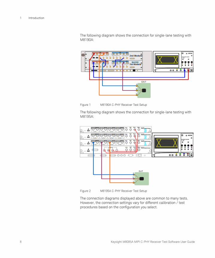
The following diagram shows the connection for single-lane testing with M8190A:
Figure 1 M8190A C-PHY Receiver Test Setup
The following diagram shows the connection for single-lane testing with M8195A:
Figure 2 M8195A C-PHY Receiver Test Setup
The connection diagrams displayed above are common to many tests. However, the connection settings vary for different calibration / test procedures based on the configuration you select.

Keysight M8085A MIPI C-PHY Receiver Test Software User Guide 9
Introduction 1
Basic Requirements
Hardware Setup
Single-lane Setup
Using M8190A AWG Module
The required hardware setup for single-lane using M8190A module are following:
• Two AWG(s) modules (M8190A)
Make sure to use the M8190A software version 5.0 or later for both AWG(s) with the following options:
• 002
• 12G
• AMP
• SEQ
• FSW
• An Embedded Controller (M9536A)
• A 5 slot AXIe chassis
• An Infiniium or SCPI compatible oscilloscope
• LAN or GPIB/USB adapter
For hardware setup, follow the given steps:
1 Put two AWG(s) (M8190A) and an Embedded Controller in the 5 slot frame AXIe chassis.
2 The Embedded Controller must be installed in the slot 1 of the AXIe chassis otherwise, it will not be able to connect to the internal PCIe interface of the frame.
3 The AWG 1 must be installed in the slot 2 and the AWG 2 must be installed in the slot 4 of the 5 slot AXIe chassis.
4 Connect an Inifniium or SCPI compatible Oscilloscope for deskewing the three data channel. This scope can be either connected via LAN or via GPIB adapter with the Embedded Controller host PC. For stability it is advised to use the GPIB adapter instead of a LAN connection.
10 Keysight M8085A MIPI C-PHY Receiver Test Software User Guide
1 Introduction
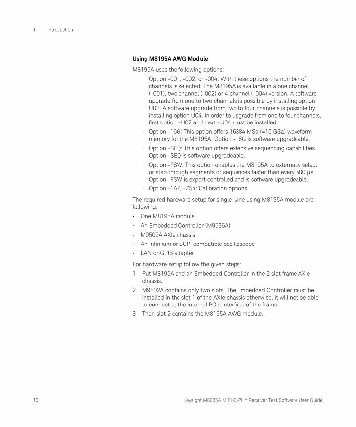
Using M8195A AWG Module
M8195A uses the following options:
• Option -001, -002, or -004: With these options the number of channels is selected. The M8195A is available in a one channel (-001), two channel (-002) or 4 channel (-004) version. A software upgrade from one to two channels is possible by installing option U02. A software upgrade from two to four channels is possible by installing option U04. In order to upgrade from one to four channels, first option –U02 and next –U04 must be installed.
• Option -16G: This option offers 16384 MSa (=16 GSa) waveform memory for the M8195A. Option -16G is software upgradeable.
• Option -SEQ: This option offers extensive sequencing capabilities. Option -SEQ is software upgradeable.
• Option -FSW: This option enables the M8195A to externally select or step through segments or sequences faster than every 500 μs. Option -FSW is export controlled and is software upgradeable.
• Option -1A7, -Z54: Calibration options.
The required hardware setup for single-lane using M8195A module are following:
• One M8195A module
• An Embedded Controller (M9536A)
• M9502A AXIe chassis
• An Infiniium or SCPI compatible oscilloscope
• LAN or GPIB adapter
For hardware setup follow the given steps:
1 Put M8195A and an Embedded Controller in the 2 slot frame AXIe chassis.
2 M9502A contains only two slots. The Embedded Controller must be installed in the slot 1 of the AXIe chassis otherwise, it will not be able to connect to the internal PCIe interface of the frame.
3 Then slot 2 contains the M8195A AWG module.

Keysight M8085A MIPI C-PHY Receiver Test Software User Guide 11
Introduction 1
Multi-lane Setup
Following hardware setup is required for multi-lane:
• Two or three M8195A AWG modules to enable the multi-lane support
• One M8197A module to synchronize multi M8195A modules
• AXIe chassis
• 5 slot AXIe chassis for two lane structure i.e. 2 slots for two M8195A modules and 1 slot for one M8197A module
• 5 slot AXIe chassis for three lane structure i.e. 3 slots for three M8195A modules and 1 slot for one M8197A module
For hardware setup (e.g. three Lane structure i.e. three M8195A modules), follow the given steps:
1 Put three M8195A and one M8197A in the 5 slot frame AXIe chassis.
2 The modules should be arranged inside a 5 slot chassis in the following order:
• Slot 1: M8197A (Used for synchronization)
• Slot 2: M8195A (Used for lane 1)
• Slot 3: M8195A (Used for lane 2)
• Slot 4: M8195A (Used for lane 3)
NOTEThe module itself is already de-skewed. It means that all the signal outs are synchronized with respect to each other, i.e. Data Out 1 is synchro-nous to rest of the data out locations.
The only prerequisite is to have ‘match pair cable’ length for normal and complement connections. This can be done by doing a de-skew calibra-tion. But it is valid only for M8190A.
NOTEM8197A module is used to synchronize M8195A modules (Lane 1, Lane 2 and Lane 3).
However, if you are using only single M8195A module (Lane 1), then M8197A is not required.
12 Keysight M8085A MIPI C-PHY Receiver Test Software User Guide
1 Introduction
Software Requirements
To install the MIPI C-PHY CTS plug-in, the M8070A software (S3.5.104.4 or above) is required. You can download the software from the following link:
http://www.keysight.com/find/M8070A
NOTEYou can also use an embedded controller for M8070A and/or the AWG SFPs. It should be installed in slot 1 of AXI chassis, thereby shifting the other modules one slot up.
NOTEThe module for multi-lane M8195A is also de-skewed itself.
Keysight M8085A MIPI C-PHY Receiver Test Software User Guide 13
Introduction 1
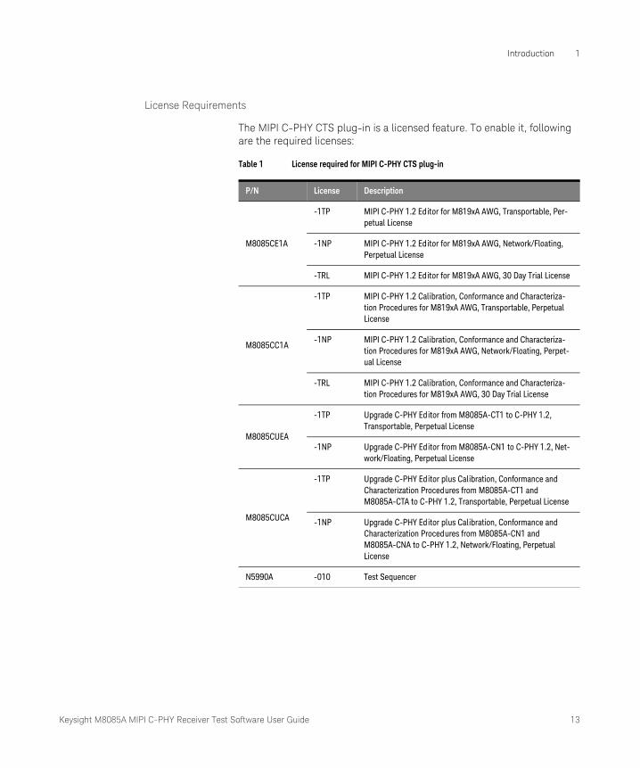
License Requirements
The MIPI C-PHY CTS plug-in is a licensed feature. To enable it, following are the required licenses:
Table 1 License required for MIPI C-PHY CTS plug-in
P/N License Description
M8085CE1A
-1TP MIPI C-PHY 1.2 Editor for M819xA AWG, Transportable, Per-petual License
-1NP MIPI C-PHY 1.2 Editor for M819xA AWG, Network/Floating, Perpetual License
-TRL MIPI C-PHY 1.2 Editor for M819xA AWG, 30 Day Trial License
M8085CC1A
-1TP MIPI C-PHY 1.2 Calibration, Conformance and Characteriza-tion Procedures for M819xA AWG, Transportable, Perpetual License
-1NP MIPI C-PHY 1.2 Calibration, Conformance and Characteriza-tion Procedures for M819xA AWG, Network/Floating, Perpet-ual License
-TRL MIPI C-PHY 1.2 Calibration, Conformance and Characteriza-tion Procedures for M819xA AWG, 30 Day Trial License
M8085CUEA
-1TP Upgrade C-PHY Editor from M8085A-CT1 to C-PHY 1.2, Transportable, Perpetual License
-1NP Upgrade C-PHY Editor from M8085A-CN1 to C-PHY 1.2, Net-work/Floating, Perpetual License
M8085CUCA
-1TP Upgrade C-PHY Editor plus Calibration, Conformance and Characterization Procedures from M8085A-CT1 and M8085A-CTA to C-PHY 1.2, Transportable, Perpetual License
-1NP Upgrade C-PHY Editor plus Calibration, Conformance and Characterization Procedures from M8085A-CN1 and M8085A-CNA to C-PHY 1.2, Network/Floating, Perpetual License
N5990A -010 Test Sequencer

14 Keysight M8085A MIPI C-PHY Receiver Test Software User Guide
1 Introduction
NOTEThe Network license for the M8085A MIPI C-PHY CTS plugin is compati-ble with both the license types of the Keysight M8070A software, that is, Network license (M8070A-0NP) and Transportable license (M8070A-0TP). For the Network license of the M8085A MIPI C-PHY CTS plugin to work, there is no need to install Keysight M8070A software's Network license (M8070A-0NP) separately in case only the Transport-able license (M8070A-0TP) is installed.

Keysight M8085A MIPI C-PHY Receiver Test Software User Guide 15
Introduction 1
Accessing the MIPI C-PHY CTS Plug-in
The MIPI C-PHY Receiver Tests Software user interface allows you to set the DUT and test configuration. It can be accessed through the M8070A system software. You must have the valid license to run the application. For licensing details, see “License Requirements” on page 13.
Follow the steps to access an installed C-PHY CTS plug-in through M8070A system software:
1 Click Start > All Programs > Keysight M8070A > Keysight M8085A. This will launch M8070A system software user interface.
2 In the M8070A user interface, from the menu bar, click Application menu. It will list all installed plug-ins.
3 Select the “MIPI C-PHY CTS” plug-in.
4 The “MIPI C-PHY CTS” plug-in interface appears as shown in Figure 3.
Figure 3 C-PHY CTS Configuration Window
16 Keysight M8085A MIPI C-PHY Receiver Test Software User Guide
1 Introduction
The MIPI C-PHY Receiver Test Software user interface consists of the following GUI elements:
• Configuration
• Parameters
• Logger
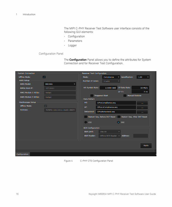
Configuration Panel
The Configuration Panel allows you to define the attributes for System Connection and for Receiver Test Configuration.
Figure 4 C-PHY CTS Configuration Panel
Keysight M8085A MIPI C-PHY Receiver Test Software User Guide 17
Introduction 1
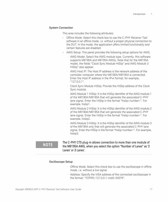
System Connection
This area includes the following attributes:
• Offline Mode: Select this check box to use the C-PHY Receiver Test software in an offline mode, i.e. without a proper physical connection to the DUT. In this mode, the application offers limited functionality and certain features are disabled.
• AWG Setup: This panel provides the following setup options for AWG.
• AWG Model: Select the AWG module type. Currently, this software supports M8190A and M8195A AWGs. Note that for the M8195A model, the fields “Clock Sync Module HiSlip” and AWG Module 3 HiSlip” also appear.
• AWG Host IP: The Host IP address is the network address of the controller computer where the M8190A/M8195A is connected. Enter the Host IP address in the IPv4 format, for example, “127.0.0.1”.
• Clock Sync Module HiSlip: Provide the HiSlip address of the Clock Sync module.
• AWG Module 1 HiSlip: It is the HiSlip identifier of the AWG module 1 of the M8190A/M8195A that will generate the associated C-PHY lane signal. Enter the HiSlip in the format “hislip<number>”. For example, hislip1.
• AWG Module 2 HiSlip: It is the HiSlip identifier of the AWG module 2 of the M8190A/M8195A that will generate the associated C-PHY lane signal. Enter the HiSlip in the format “hislip<number>”. For example, hislip2.
• AWG Module 3 HiSlip: It is the HiSlip identifier of the AWG module 3 of the M8195A only that will generate the associated C-PHY lane signal. Enter the HiSlip in the format “hislip<number>”. For example, hislip3.
Oscilloscope Setup
• Offline Mode: Select this check box to use the oscilloscope in offline mode, i.e. without a live signal.
• Address: Specify the VISA address of the connected oscilloscope in the format: “TCPIP0::127.0.0.1::inst0::INSTR”.
NOTEThe C-PHY CTS plug-in allows connection to more than one module of the M8195A AWG, when you select the option “Number of Lanes” as ‘2 Lanes’ or 3 Lanes’.
18 Keysight M8085A MIPI C-PHY Receiver Test Software User Guide
1 Introduction
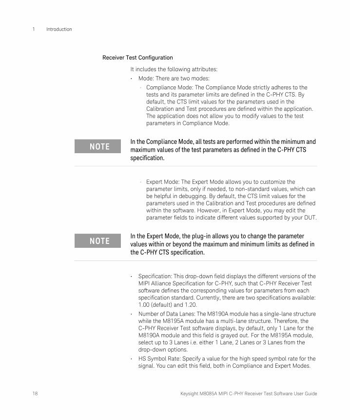
Receiver Test Configuration
It includes the following attributes:
• Mode: There are two modes:
• Compliance Mode: The Compliance Mode strictly adheres to the tests and its parameter limits are defined in the C-PHY CTS. By default, the CTS limit values for the parameters used in the Calibration and Test procedures are defined within the application. The application does not allow you to modify values to the test parameters in Compliance Mode.
• Expert Mode: The Expert Mode allows you to customize the parameter limits, only if needed, to non-standard values, which can be helpful in debugging. By default, the CTS limit values for the parameters used in the Calibration and Test procedures are defined within the software. However, in Expert Mode, you may edit the parameter fields to indicate different values supported by your DUT.
• Specification: This drop-down field displays the different versions of the MIPI Alliance Specification for C-PHY, such that C-PHY Receiver Test software defines the corresponding values for parameters from each specification standard. Currently, there are two specifications available: 1.00 (default) and 1.20.
• Number of Data Lanes: The M8190A module has a single-lane structure while the M8195A module has a multi-lane structure. Therefore, the C-PHY Receiver Test software displays, by default, only 1 Lane for the M8190A module and this field is grayed out. For the M8195A module, select up to 3 Lanes i.e. either 1 Lane, 2 Lanes or 3 Lanes from the drop-down options.
• HS Symbol Rate: Specify a value for the high speed symbol rate for the signal. You can edit this field, both in Compliance and Expert Modes.
NOTEIn the Compliance Mode, all tests are performed within the minimum and maximum values of the test parameters as defined in the C-PHY CTS specification.
NOTEIn the Expert Mode, the plug-in allows you to change the parameter values within or beyond the maximum and minimum limits as defined in the C-PHY CTS specification.
Keysight M8085A MIPI C-PHY Receiver Test Software User Guide 19
Introduction 1
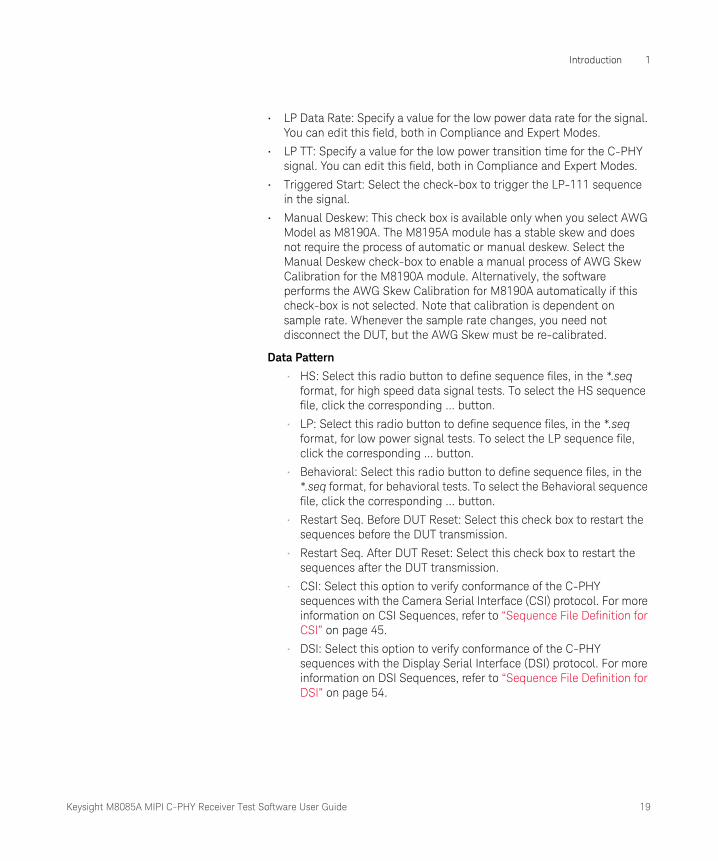
• LP Data Rate: Specify a value for the low power data rate for the signal. You can edit this field, both in Compliance and Expert Modes.
• LP TT: Specify a value for the low power transition time for the C-PHY signal. You can edit this field, both in Compliance and Expert Modes.
• Triggered Start: Select the check-box to trigger the LP-111 sequence in the signal.
• Manual Deskew: This check box is available only when you select AWG Model as M8190A. The M8195A module has a stable skew and does not require the process of automatic or manual deskew. Select the Manual Deskew check-box to enable a manual process of AWG Skew Calibration for the M8190A module. Alternatively, the software performs the AWG Skew Calibration for M8190A automatically if this check-box is not selected. Note that calibration is dependent on sample rate. Whenever the sample rate changes, you need not disconnect the DUT, but the AWG Skew must be re-calibrated.
Data Pattern
• HS: Select this radio button to define sequence files, in the *.seq format, for high speed data signal tests. To select the HS sequence file, click the corresponding ... button.
• LP: Select this radio button to define sequence files, in the *.seq format, for low power signal tests. To select the LP sequence file, click the corresponding ... button.
• Behavioral: Select this radio button to define sequence files, in the *.seq format, for behavioral tests. To select the Behavioral sequence file, click the corresponding ... button.
• Restart Seq. Before DUT Reset: Select this check box to restart the sequences before the DUT transmission.
• Restart Seq. After DUT Reset: Select this check box to restart the sequences after the DUT transmission.
• CSI: Select this option to verify conformance of the C-PHY sequences with the Camera Serial Interface (CSI) protocol. For more information on CSI Sequences, refer to “Sequence File Definition for CSI” on page 45.
• DSI: Select this option to verify conformance of the C-PHY sequences with the Display Serial Interface (DSI) protocol. For more information on DSI Sequences, refer to “Sequence File Definition for DSI” on page 54.
20 Keysight M8085A MIPI C-PHY Receiver Test Software User Guide
1 Introduction
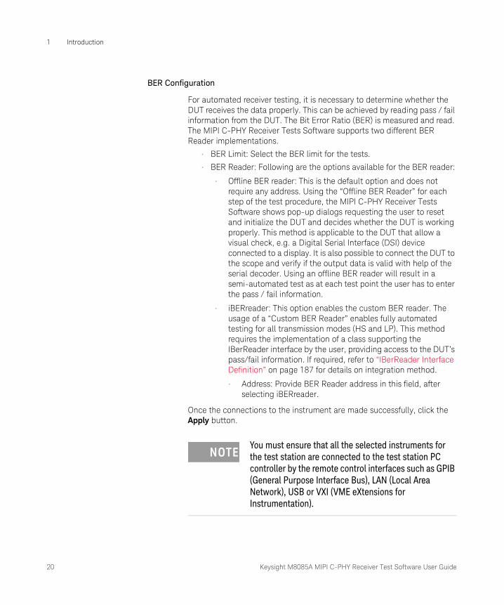
BER Configuration
For automated receiver testing, it is necessary to determine whether the DUT receives the data properly. This can be achieved by reading pass / fail information from the DUT. The Bit Error Ratio (BER) is measured and read. The MIPI C-PHY Receiver Tests Software supports two different BER Reader implementations.
• BER Limit: Select the BER limit for the tests.
• BER Reader: Following are the options available for the BER reader:
• Offline BER reader: This is the default option and does not require any address. Using the “Offline BER Reader” for each step of the test procedure, the MIPI C-PHY Receiver Tests Software shows pop-up dialogs requesting the user to reset and initialize the DUT and decides whether the DUT is working properly. This method is applicable to the DUT that allow a visual check, e.g. a Digital Serial Interface (DSI) device connected to a display. It is also possible to connect the DUT to the scope and verify if the output data is valid with help of the serial decoder. Using an offline BER reader will result in a semi-automated test as at each test point the user has to enter the pass / fail information.
• iBERreader: This option enables the custom BER reader. The usage of a “Custom BER Reader” enables fully automated testing for all transmission modes (HS and LP). This method requires the implementation of a class supporting the IBerReader interface by the user, providing access to the DUT’s pass/fail information. If required, refer to “IBerReader Interface Definition” on page 187 for details on integration method.
• Address: Provide BER Reader address in this field, after selecting iBERreader.
Once the connections to the instrument are made successfully, click the Apply button.
NOTEYou must ensure that all the selected instruments for the test station are connected to the test station PC controller by the remote control interfaces such as GPIB (General Purpose Interface Bus), LAN (Local Area Network), USB or VXI (VME eXtensions for Instrumentation).

Keysight M8085A MIPI C-PHY Receiver Test Software User Guide 21
Introduction 1
Parameters Panel
The Parameters Panel allows you to change the Idle Voltage, Protocol timings supported by the DUT and the signal levels.
Figure 5 Parameters Panel
Idle Voltage
The parameter for Idle Voltage is shown in Figure 6 and described below.
Figure 6 Idle Voltage Parameter
Idle Voltage: The Idle voltage sets the offset on the AWG output amplifiers. This is the output offset voltage when the AWGs are in the Stop state.
22 Keysight M8085A MIPI C-PHY Receiver Test Software User Guide
1 Introduction
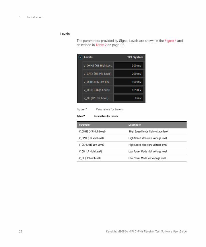
Levels
The parameters provided by Signal Levels are shown in the Figure 7 and described in Table 2 on page 22.
Figure 7 Parameters for Levels
Table 2 Parameters for Levels
Parameter Description
V_OHHS (HS High Level) High Speed Mode high voltage level
V_CPTX (HS Mid Level) High Speed Mode mid voltage level
V_OLHS (HS Low Level) High Speed Mode low voltage level
V_OH (LP High Level) Low Power Mode high voltage level
V_OL (LP Low Level) Low Power Mode low voltage level

Keysight M8085A MIPI C-PHY Receiver Test Software User Guide 23
Introduction 1
Timings
The parameters provided by Timings are shown in the Figure 8 and described in Table 3 on page 23.
Figure 8 Parameters for Timings
Table 3 Parameters for Timings
Parameter Description
T3-PREPARE Sets the time that the transmitter drives a LP-000 state immediately before the start of high speed transmission.
T3-PREBEGIN Sets the T3-PREBEGIN pattern in high-speed C-PHY pattern format. It should be a multiple of 7 UI from a minimum of 7UI to 448 UI.
T3-PREEND Sets the T3-PREEND pattern in high-speed C-PHY pattern format. By default, this pattern contains a total of 7 symbols of type 3.
T3-PROGSEQ Sets the optional T3-PROGSEQ pattern in high-speed C-PHY pattern format.
T3-SYNC Sets the T3-SYNC, which is sent immediately before staring high-speed transmission. By default, the pattern is 3444443.
24 Keysight M8085A MIPI C-PHY Receiver Test Software User Guide
1 Introduction
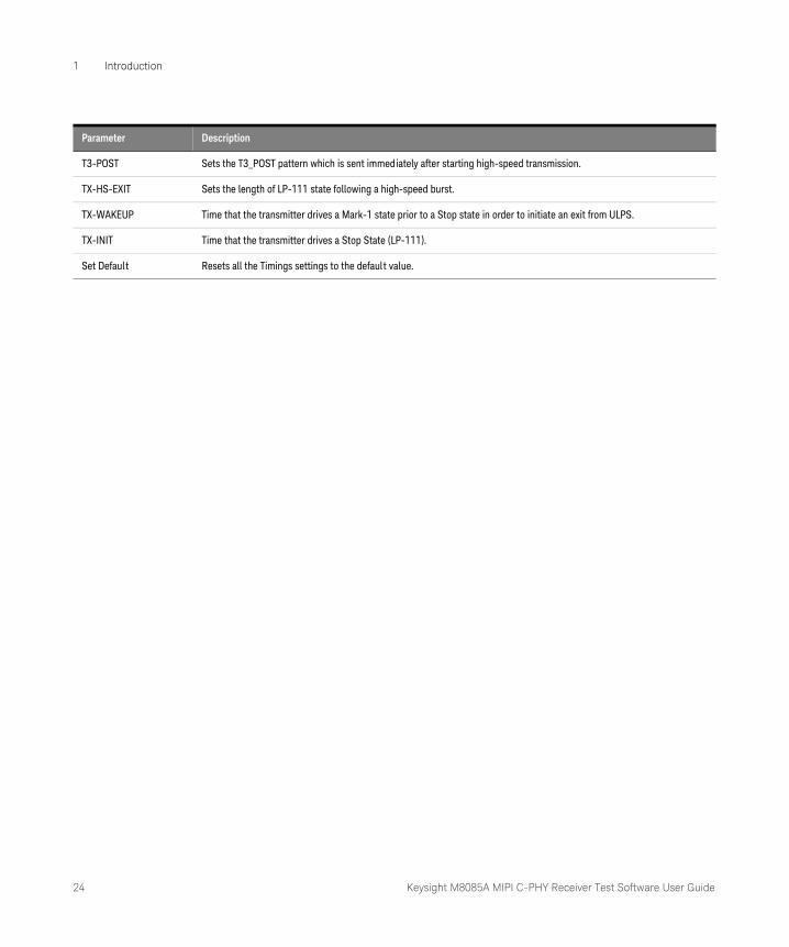
T3-POST Sets the T3_POST pattern which is sent immediately after starting high-speed transmission.
TX-HS-EXIT Sets the length of LP-111 state following a high-speed burst.
TX-WAKEUP Time that the transmitter drives a Mark-1 state prior to a Stop state in order to initiate an exit from ULPS.
TX-INIT Time that the transmitter drives a Stop State (LP-111).
Set Default Resets all the Timings settings to the default value.
Parameter Description

Keysight M8085A MIPI C-PHY Receiver Test Software User Guide 25
Introduction 1
Logger Panel
The Logger Panel displays errors, warnings and information messages along with their respective descriptions, applications from where they are generated and their time stamps.
Figure 9 Logger Panel
26 Keysight M8085A MIPI C-PHY Receiver Test Software User Guide
1 Introduction
Running Tests
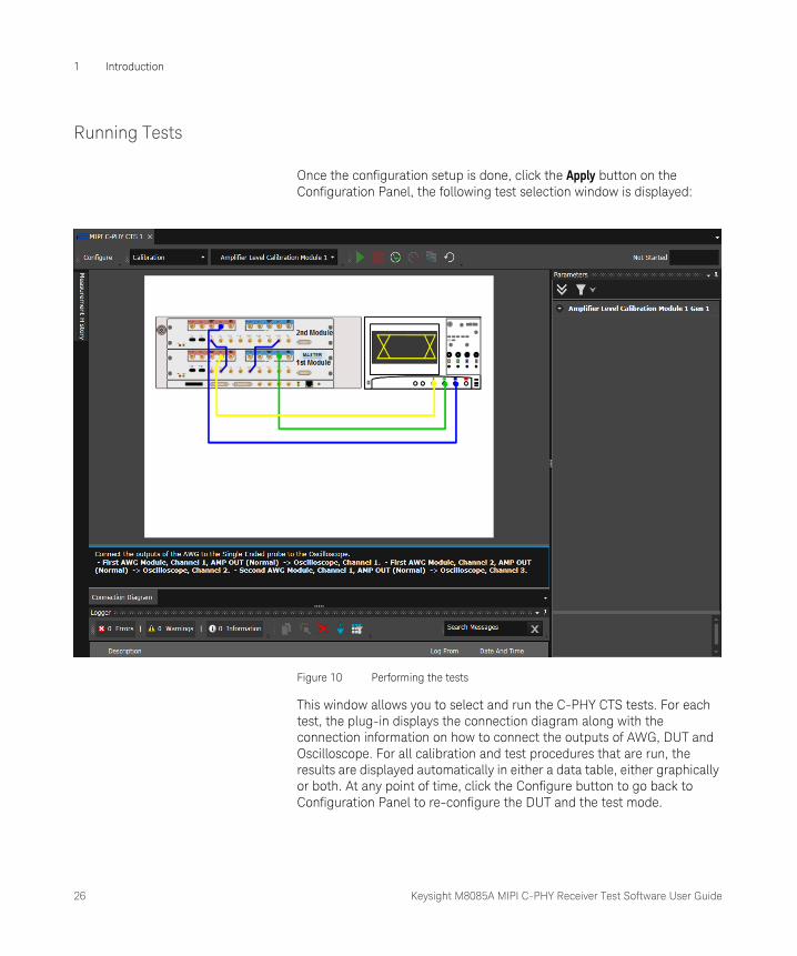
Once the configuration setup is done, click the Apply button on the Configuration Panel, the following test selection window is displayed:
Figure 10 Performing the tests
This window allows you to select and run the C-PHY CTS tests. For each test, the plug-in displays the connection diagram along with the connection information on how to connect the outputs of AWG, DUT and Oscilloscope. For all calibration and test procedures that are run, the results are displayed automatically in either a data table, either graphically or both. At any point of time, click the Configure button to go back to Configuration Panel to re-configure the DUT and the test mode.
Keysight M8085A MIPI C-PHY Receiver Test Software User Guide 27
Introduction 1
This window has the following options:
1 Toolbar Buttons: The following table shows the available buttons on the toolbar:
Table 4 Toolbar Buttons
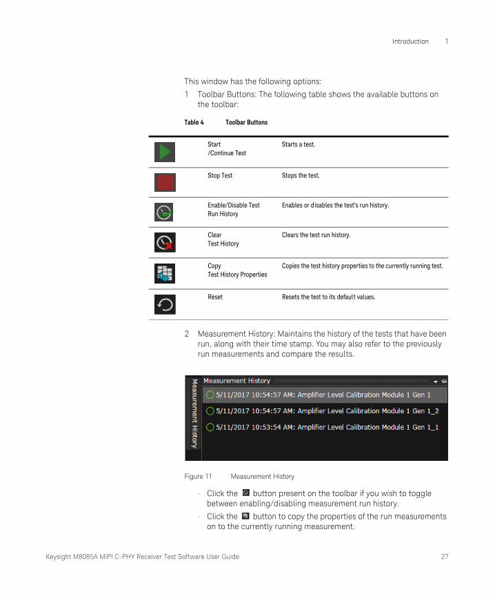
2 Measurement History: Maintains the history of the tests that have been run, along with their time stamp. You may also refer to the previously run measurements and compare the results.
Figure 11 Measurement History
• Click the button present on the toolbar if you wish to toggle between enabling/disabling measurement run history.
• Click the button to copy the properties of the run measurements on to the currently running measurement.
Start/Continue Test
Starts a test.
Stop Test Stops the test.
Enable/Disable Test Run History
Enables or disables the test’s run history.
ClearTest History
Clears the test run history.
CopyTest History Properties
Copies the test history properties to the currently running test.
Reset Resets the test to its default values.
28 Keysight M8085A MIPI C-PHY Receiver Test Software User Guide
1 Introduction
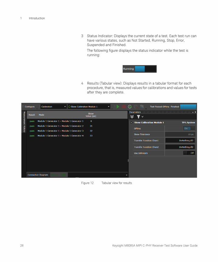
3 Status Indicator: Displays the current state of a test. Each test run can have various states, such as Not Started, Running, Stop, Error, Suspended and Finished.
The following figure displays the status indicator while the test is running:
4 Results (Tabular view): Displays results in a tabular format for each procedure, that is, measured values for calibrations and values for tests after they are complete.
Figure 12 Tabular view for results
Keysight M8085A MIPI C-PHY Receiver Test Software User Guide 29
Introduction 1
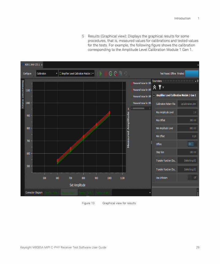
5 Results (Graphical view): Displays the graphical results for some procedures, that is, measured values for calibrations and tested values for the tests. For example, the following figure shows the calibration corresponding to the Amplitude Level Calibration Module 1 Gen 1.
Figure 13 Graphical view for results

30 Keysight M8085A MIPI C-PHY Receiver Test Software User Guide
1 Introduction

Keysight M8085A MIPI C-PHY Receiver Test Software
User Guide
2 Sequence and Data Files
Patterns, Data Format and Sequences / 32CSI and DSI Sequences / 42Sequence File Definition for CSI / 45Sequence File Definition for DSI / 54

32 Keysight M8085A MIPI C-PHY Receiver Test Software User Guide
2 Sequence and Data Files
Patterns, Data Format and Sequences
Overview
• The Pattern Mode has a *.ptrn file, which contains the definition of LP and/or HS C-PHY states. The pattern files are loaded with the extension of ‘*.ptrn’ and write in terms of line states.
• The Burst Mode is a block of binary data, which are converted to C-PHY states, and is repeated infinitely. The burst block may contain either LP Data and HS Data both, pure LP data, or pure HS data, depending on the content of the data given for HS and LP. The files are loaded with the extension of ‘*.dat’.
• The Pure HS mode contains only HS data and no LP111 transitions are included. For pure HS mode, all the LP data is neglected.
• The Frame mode allows to organize the data in blocks, and a sequence of blocks containing loops. The definition of a sequence is done via a sequence file and it can be loaded with the extension ‘*.seq’. Each individual block can be repeated (“looped”) N-times and the number of repetitions N can be selected for each block separately. In addition to the sequence file, the frame mode may require one or more data files.
NOTECurrently, the Data Pattern in the C-PHY CTS plug-in can be defined in the Frame Mode only, that is, using sequence files. However, a sequence file can contain *.ptrn or *.dat/*.txt file names defined within the blocks. The actual *.ptrn or *.dat/*txt files must be included in the same folder location as the sequence (*.seq) files.
D-PHY CTS plug-ins cannot use a sequence that contains C-PHY specific macros such as three wire LP states (for example, LP000, LP011, etc.) or the P-Macro (for example, P"Patternfile.ptrn"). Otherwise, both C-PHY and D-PHY CTS plug-ins use the same sequence structure.

Keysight M8085A MIPI C-PHY Receiver Test Software User Guide 33
Sequence and Data Files 2
*.ptrn File Format (P Macro)
The following table shows the line states available in High-Speed Mode:
Table 5 Line States
The following table shows the symbols (transitions) available in High-Speed Mode:
Table 6 Symbol (Transitions))
The following table shows the line states provided by Low Power Mode:
Table 7 Lines states provided by Low Power Mode
Pattern File Entry Line State Line State {Line A, Line B, Line C}
X +x {1, 0, ½ }
x -x {0, 1, ½ }
Y +y {½ , 1, 0}
y -y {½, 0, 1}
Z +z {0, ½, 1}
z -z {1, ½, 0}
Pattern File Entry Symbol Input Value Activity
0 000 Rotate CCW, polarity stays same
1 001 Rotate CCW, polarity is inverted
2 010 Rotate CW, polarity stays same
3 011 Rotate CW, polarity is inverted
4 1xx Same phase, polarity is inverted
Pattern File Entry
Line A Line B Line C Activity
L 0 0 0 One “L” sets all three wires to low state

34 Keysight M8085A MIPI C-PHY Receiver Test Software User Guide
2 Sequence and Data Files
Pattern Coding Examples
The following table shows the example of different types of patten coding used:
Table 8 Pattern Coding Examples
C 0 0 1 One pattern file entry defines the state of all 3 wires (1 Symbol).An upper case letter means only the selected wire is high, the 2 other wires are low.A lower case letter means only the selected wire is low, the 2 other wires are high.
B 0 1 0
a 0 1 1
A 1 0 0
b 1 0 1
c 1 1 0
H 1 1 1 One “H” sets all three wires to high state
Pattern File Entry
Line A Line B Line C Activity
Pattern Cod ing Line States Description
X0123 (XZyzX) 210432113Resulting Line States: X -> YxzZxyXzX
High speed init pattern and high speed loop pattern. The high speed signal can be coded with transition symbols too.
X0123 (XZyzX) %0101000011101101%Resulting Transitions: X -> 1432300Resulting Line States: zZxyZYX
High speed init pattern and coded binary loop pattern. Between the percentage symbols (%) binary coding can be used. The last wire state of the init pattern needs to be equal to the last wire state of the loop pattern (X). If this is not the case coding of the looped pattern will be erroneous.
xXyx X0241%1011011101001010%xResulting Line States: X ZXxZ yYzxYZY x
High speed init pattern and high speed loop pattern mixed with binary coding. You can mix the use of wire states, transition symbols and binary coding. This is mainly useful for introducing coding errors.
HLB xYzxZyyZy Low power init pattern and high speed loop pattern. There will be a low power to high speed transition at the end of the init pattern.
HLBZ xYzxZyyZ Mixed low power/high speed init pattern and high speed loop pattern. The transition from low power to high speed will happen within the init pattern.

Keysight M8085A MIPI C-PHY Receiver Test Software User Guide 35
Sequence and Data Files 2
acL y -> 0120412CLAbc Low power init pattern and high speed and low power loop pattern. There will be a high speed low power transition within the loop pattern and a low power high speed transition at the end of the loop pattern.Limitation: The “LP->HS Start Wire State” cannot be modified.
Expanded Pattern
Wire States
Expanded Pattern
Wire States
Init Pattern
acL acL Loop Pattern 1 0120412 xZXZzYZ
LP->HS Start
H H HS->LP Post 4444444 zZzZzZz
LP->HS Request
C C HS->LP Exit C C
LP->HS Prepare
L L Loop Pattern 2 CLAbc CLAbc
LP->HS Start Wire State
X X LP->HS Start H H
LP->HS Preamble
3333333 yZxYzXy LP->HS Request C C
LP->HS Pre-End
3333333 ZxYzXyZ LP->HS Prepare L L
LP->HS Sync
3444443 xXxXxXy LP->HS Start Wire State
X X
LP->HS Preamble 3333333 yZxYzXy
LP->HS Pre-End 3333333 ZxYzXyZ
LP->HS Sync 3444443 xXxXxXy
Pattern Cod ing Line States Description
36 Keysight M8085A MIPI C-PHY Receiver Test Software User Guide
2 Sequence and Data Files
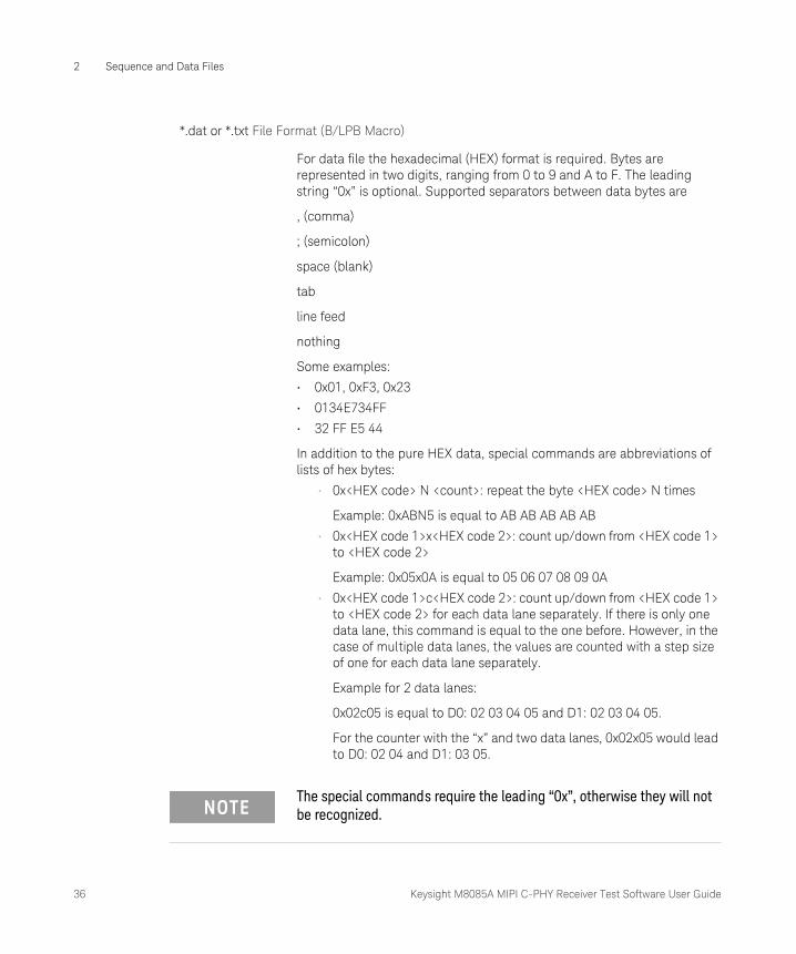
*.dat or *.txt File Format (B/LPB Macro)
For data file the hexadecimal (HEX) format is required. Bytes are represented in two digits, ranging from 0 to 9 and A to F. The leading string “0x” is optional. Supported separators between data bytes are
, (comma)
; (semicolon)
space (blank)
tab
line feed
nothing
Some examples:
• 0x01, 0xF3, 0x23
• 0134E734FF
• 32 FF E5 44
In addition to the pure HEX data, special commands are abbreviations of lists of hex bytes:
• 0x<HEX code> N <count>: repeat the byte <HEX code> N times
Example: 0xABN5 is equal to AB AB AB AB AB
• 0x<HEX code 1>x<HEX code 2>: count up/down from <HEX code 1> to <HEX code 2>
Example: 0x05x0A is equal to 05 06 07 08 09 0A
• 0x<HEX code 1>c<HEX code 2>: count up/down from <HEX code 1> to <HEX code 2> for each data lane separately. If there is only one data lane, this command is equal to the one before. However, in the case of multiple data lanes, the values are counted with a step size of one for each data lane separately.
Example for 2 data lanes:
0x02c05 is equal to D0: 02 03 04 05 and D1: 02 03 04 05.
For the counter with the “x” and two data lanes, 0x02x05 would lead to D0: 02 04 and D1: 03 05.
NOTEThe special commands require the leading “0x”, otherwise they will not be recognized.
Keysight M8085A MIPI C-PHY Receiver Test Software User Guide 37
Sequence and Data Files 2
*.seq File Format
In the sequence file the data rate, data blocks and sequence are defined. Note that all parameters are even integers. The structure of a sequence file is shown inFigure 14.
HSFreq: <frequency in bits/s>
Blocks:
<BlockName 1>: <Block Definition 1>, …, <Block Definition n1>;
…
<BlockName M>: <Block Definition 1>, …,<Block Definition nM>;
Sequence:
1. <BlockName J>, <Loop Count R>; - First block
…
<N>. <BlockName K>, <Loop Count S>; - Nth block
…
<P>. <BlockName L>, <Loop Count T>; - Pth block
[LoopTo N]

38 Keysight M8085A MIPI C-PHY Receiver Test Software User Guide
2 Sequence and Data Files Figure 14 Block Diagram of the structure of sequence file
Each block may comprise multiple sub-blocks (1 to n). Sub-blocks can be used in multiple blocks. In the sequence, blocks can be used as often as needed. Within the sequence, the “LoopTo” expression starts an infinite loop from block <N> to the last block <P>. If no “LoopTo” expression is specified, an infinite loop is created from block 1 to block P (last block). The valid block definitions (macros) may contain the following data:
• LP000, LP001, LP010, LP011, LP100,..,LP111: for a single LP state.
• LPB “<filename>”: for generating LP data specified in the file with the name <filename>. The file should be in the same folder as the sequence file. At the beginning of the data an escape trigger for LP or ULP data mode is sent before the data and a Mark-0/1 sequence is sent after the end of the data. For the data, the data file format given above must be used.
• LP<00, 01, 10, or 11, 000, …, 111> N <number of bits>: The LP state is sent <number of [HS] bits> times.
• LP<00, 01, 10, or 11 000, …, 111> E <number of bits>: The LP state is sent until the block size reaches the number of HS bits given in <number of bits>.
Keysight M8085A MIPI C-PHY Receiver Test Software User Guide 39
Sequence and Data Files 2
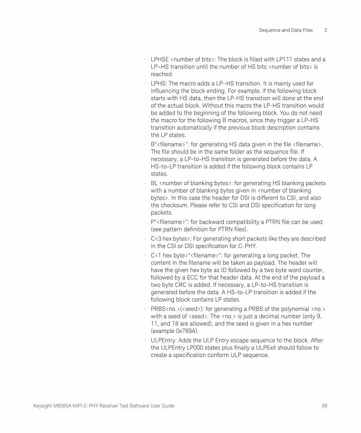
• LPHSE <number of bits>: The block is filled with LP111 states and a LP–HS transition until the number of HS bits <number of bits> is reached.
• LPHS: The macro adds a LP–HS transition. It is mainly used for influencing the block ending. For example, if the following block starts with HS data, then the LP-HS transition will done at the end of the actual block. Without this macro the LP-HS transition would be added to the beginning of the following block. You do not need the macro for the following B macros, since they trigger a LP-HS transition automatically if the previous block description contains the LP states.
• B“<filename>”: for generating HS data given in the file <filename>. The file should be in the same folder as the sequence file. If necessary, a LP-to-HS transition is generated before the data. A HS-to-LP transition is added if the following block contains LP states.
• BL <number of blanking bytes>: for generating HS blanking packets with a number of blanking bytes given in <number of blanking bytes>. In this case the header for DSI is different to CSI, and also the checksum. Please refer to CSI and DSI specification for long packets.
• P“<filename>”: for backward compatibility a PTRN file can be used (see pattern definition for PTRN files).
• C<3 hex bytes>: For generating short packets like they are described in the CSI or DSI specification for C-PHY.
• C<1 hex byte>“<filename>”: for generating a long packet. The content in the filename will be taken as payload. The header will have the given hex byte as ID followed by a two byte word counter, followed by a ECC for that header data. At the end of the payload a two byte CRC is added. If necessary, a LP-to-HS transition is generated before the data. A HS-to-LP transition is added if the following block contains LP states.
• PRBS<no.>(<seed>): for generating a PRBS of the polynomial <no.> with a seed of <seed>. The <no.> is just a decimal number (only 9, 11, and 18 are allowed), and the seed is given in a hex number (example 0x789A).
• ULPEntry: Adds the ULP Entry escape sequence to the block. After the ULPEntry LP000 states plus finally a ULPExit should follow to create a specification conform ULP sequence.

40 Keysight M8085A MIPI C-PHY Receiver Test Software User Guide
2 Sequence and Data Files
• ULPExit <number of LP100 states>: Creates a ULP exit sequence. It is not allowed to combine this block definitions with other definitions, which means in this case the block must only contain this macro and no other.
In any case, an LP111 block is added to each sequence. A LP–HS transition is added if needed to switch the device into HS mode. These blocks need not to be added explicitly to the sequence. They are added automatically for all sequences, i.e. even if a sequence with pure HS blocks is given.
Example of a Sequence File:
HSFreq: 200MBit/s;
Blocks:
LPInit1: LPB"Esc0ms.txt",LP111E13728;
LPPause: LP111N1024;
LPInit2: LPB"Esc100ms.txt",LP111E13728;
LPInit3: LPB"Esc200ms.txt",LP111E13728;
Header: B"FirstHsLine.txt",LP111E6016;
Video: B"VideoLine.txt",LP111E6016;
Sequence:
1 LPInit1,1;
2 LPPause,20000;
NOTE• If blocks are looped, then the beginning of the block should have the
same kind of data mode (LP or HS) as the block following it, otherwise the block loop will result in invalid LP-to-HS transitions.
• Video Frames that contain LP111 blanking periods should be rotated so that the block definition always ends with a LP111E command.
• If only the header contains LP111 states, the header block should end with LPHSE to start the HS transmission at the end of the header block.
• In case of PureHS mode, an initial LP to HS transition is added in the form of a hidden intro block in the waveform generation, before an infinite loop of pure HS data stream is generated.

Keysight M8085A MIPI C-PHY Receiver Test Software User Guide 41
Sequence and Data Files 2
3 LPInit2,1;
4 LPPause,20000;
5 LPInit3,1;
6 LPPause,20000;
7 Header,1;
8 Video,319;
LoopTo 6;
The following sections describe the various elements of a sequence file for the CSI and DSI protocols, such that the sequence file definition generates a waveform that conforms to the MIPI Specification for Camera Serial Interface (CSI) and MIPI Alliance Specification for Display Serial Interface (DSI), respectively.

42 Keysight M8085A MIPI C-PHY Receiver Test Software User Guide
2 Sequence and Data Files
CSI and DSI Sequences
Generally, a sequence file consists of three elements that form together a sequence:
• HS Data Rate
• Blocks
• Sequence
Following is a real time example of a sequence file definition:
Example of a Sequence File Definition:
HSFreq: 200MBit/s;
Blocks:
LPInit1: LPB"Esc0ms.txt",LP111E13728;
LPPause: LP111N1024;
LPInit2: LPB"Esc100ms.txt",LP111E13728;
LPInit3: LPB"Esc200ms.txt",LP111E13728;
Header: B"FirstHsLine.txt",LP111E6016;
Video: B"VideoLine.txt",LP111E6016;
Sequence:
1 LPInit1,1;
2 LPPause,20000;
3 LPInit2,1;
4 LPPause,20000;
5 LPInit3,1;
6 LPPause,20000;
7 Header,1;
8 Video,319;
LoopTo 6;
Keysight M8085A MIPI C-PHY Receiver Test Software User Guide 43
Sequence and Data Files 2
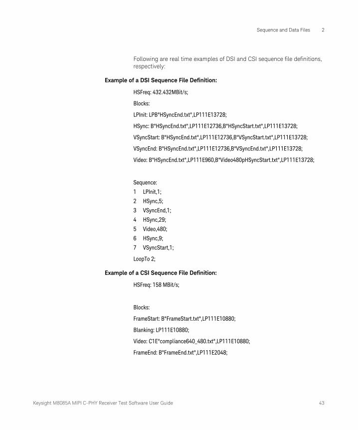
Following are real time examples of DSI and CSI sequence file definitions, respectively:
Example of a DSI Sequence File Definition:
HSFreq: 432.432MBit/s;
Blocks:
LPInit: LPB"HSyncEnd.txt",LP111E13728;
HSync: B"HSyncEnd.txt",LP111E12736,B"HSyncStart.txt",LP111E13728;
VSyncStart: B"HSyncEnd.txt",LP111E12736,B"VSyncStart.txt",LP111E13728;
VSyncEnd: B"HSyncEnd.txt",LP111E12736,B"VSyncEnd.txt",LP111E13728;
Video: B"HSyncEnd.txt",LP111E960,B"Video480pHSyncStart.txt",LP111E13728;
Sequence:
1 LPInit,1;
2 HSync,5;
3 VSyncEnd,1;
4 HSync,29;
5 Video,480;
6 HSync,9;
7 VSyncStart,1;
LoopTo 2;
Example of a CSI Sequence File Definition:
HSFreq: 158 MBit/s;
Blocks:
FrameStart: B"FrameStart.txt",LP111E10880;
Blanking: LP111E10880;
Video: C1E"compliance640_480.txt",LP111E10880;
FrameEnd: B"FrameEnd.txt",LP111E2048;
44 Keysight M8085A MIPI C-PHY Receiver Test Software User Guide
2 Sequence and Data Files
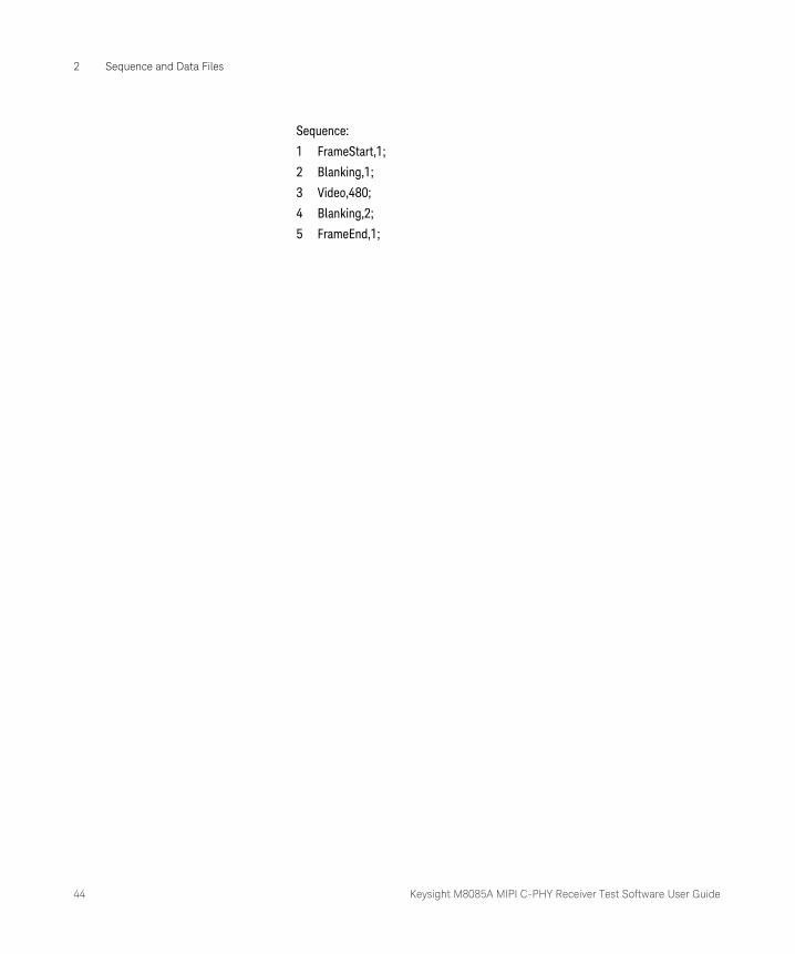
Sequence:
1 FrameStart,1;
2 Blanking,1;
3 Video,480;
4 Blanking,2;
5 FrameEnd,1;

Keysight M8085A MIPI C-PHY Receiver Test Software User Guide 45
Sequence and Data Files 2
Sequence File Definition for CSI
Overview
CSI is a MIPI Alliance standard for serial interface between a camera module and host processor. CSI adheres to the Low-Level Protocol (LLP), which is a byte orientated, packet based protocol that supports the transport of arbitrary data using Short and Long packet formats. Two packet structures are defined for low-level protocol communication: Long packets and Short packets. The format and length of Short and Long Packets depends on the choice of physical layer (C-PHY or D-PHY). For each packet structure, exit from the low power state followed by the Start of Transmission (SoT) sequence indicates the start of the packet. The End of Transmission (EoT) sequence followed by the low power state indicates the end of the packet. However, in CSI implementation, one burst consists of only one packet and LP11 (or LP111 in C-PHY) state must be inserted before the start of a burst. Since it requires to go to LP state always, an explicit EoT packet is not required.
Long and Short Packet Formats
Long Packet
For D-PHY, a Long Packet shall be identified by Data Types 0x10 to 0x37. A Long Packet for the D-PHY physical layer option shall consist of three elements: a 32-bit Packet Header (PH), an application specific Data Payload with a variable number of 8-bit data words, and a 16-bit Packet Footer (PF). The Packet Header is further composed of three elements: an 8-bit Data Identifier, a 16-bit Word Count field and an 8-bit ECC. The Packet footer has one element, a 16-bit checksum (CRC).
For C-PHY, the Long Packet structure for the C-PHY physical layer option shall consist of four elements: a Packet Header (PH), an application specific Data Payload with a variable number of 8-bit data words, a 16-bit Packet Footer (PF), and zero or more Filler bytes (FILLER). The Packet Header is 6N x 16-bits long, where N is the number of C-PHY physical layer Lanes. The Packet Header consists of two identical 6N-byte halves, where each half consists of N sequential copies of each of the following
NOTEA sequence file used for D-PHY or C-PHY conformance testing cannot be used for CSI/DSI conformance testing unless the header, payload and checksum data is included in the CSI/DSI block definitions in the sequences else the device rejects the packet.
46 Keysight M8085A MIPI C-PHY Receiver Test Software User Guide
2 Sequence and Data Files
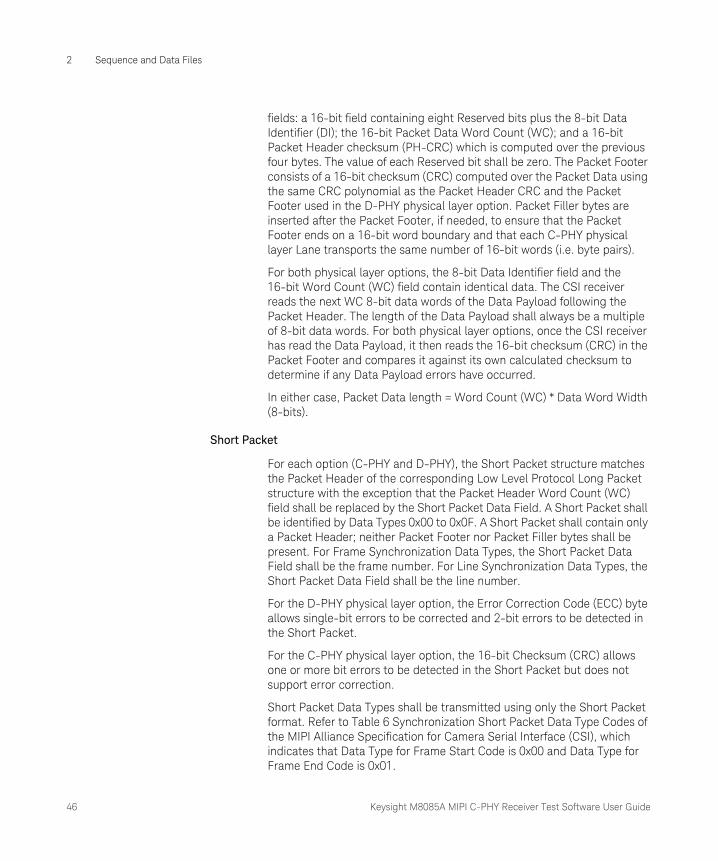
fields: a 16-bit field containing eight Reserved bits plus the 8-bit Data Identifier (DI); the 16-bit Packet Data Word Count (WC); and a 16-bit Packet Header checksum (PH-CRC) which is computed over the previous four bytes. The value of each Reserved bit shall be zero. The Packet Footer consists of a 16-bit checksum (CRC) computed over the Packet Data using the same CRC polynomial as the Packet Header CRC and the Packet Footer used in the D-PHY physical layer option. Packet Filler bytes are inserted after the Packet Footer, if needed, to ensure that the Packet Footer ends on a 16-bit word boundary and that each C-PHY physical layer Lane transports the same number of 16-bit words (i.e. byte pairs).
For both physical layer options, the 8-bit Data Identifier field and the 16-bit Word Count (WC) field contain identical data. The CSI receiver reads the next WC 8-bit data words of the Data Payload following the Packet Header. The length of the Data Payload shall always be a multiple of 8-bit data words. For both physical layer options, once the CSI receiver has read the Data Payload, it then reads the 16-bit checksum (CRC) in the Packet Footer and compares it against its own calculated checksum to determine if any Data Payload errors have occurred.
In either case, Packet Data length = Word Count (WC) * Data Word Width (8-bits).
Short Packet
For each option (C-PHY and D-PHY), the Short Packet structure matches the Packet Header of the corresponding Low Level Protocol Long Packet structure with the exception that the Packet Header Word Count (WC) field shall be replaced by the Short Packet Data Field. A Short Packet shall be identified by Data Types 0x00 to 0x0F. A Short Packet shall contain only a Packet Header; neither Packet Footer nor Packet Filler bytes shall be present. For Frame Synchronization Data Types, the Short Packet Data Field shall be the frame number. For Line Synchronization Data Types, the Short Packet Data Field shall be the line number.
For the D-PHY physical layer option, the Error Correction Code (ECC) byte allows single-bit errors to be corrected and 2-bit errors to be detected in the Short Packet.
For the C-PHY physical layer option, the 16-bit Checksum (CRC) allows one or more bit errors to be detected in the Short Packet but does not support error correction.
Short Packet Data Types shall be transmitted using only the Short Packet format. Refer to Table 6 Synchronization Short Packet Data Type Codes of the MIPI Alliance Specification for Camera Serial Interface (CSI), which indicates that Data Type for Frame Start Code is 0x00 and Data Type for Frame End Code is 0x01.
Keysight M8085A MIPI C-PHY Receiver Test Software User Guide 47
Sequence and Data Files 2
Frame and Line Synchronization Packets
Frame Synchronization Packets
Each image frame shall begin with a Frame Start (FS) Packet containing the Frame Start Code. The FS Packet shall be followed by one or more long packets containing image data and zero or more short packets containing synchronization codes. Each image frame shall end with a Frame End (FE) Packet containing the Frame End Code. For FS and FE synchronization packets, the Short Packet Data Field shall contain a 16-bit frame number. This frame number shall be the same for the FS and FE synchronization packets corresponding to a given frame.
Line Synchronization Packets
Line synchronization packets are optional. For Line Start (LS) and Line End (LE) synchronization packets, the Short Packet Data Field shall contain a 16-bit line number. This line number shall be the same for the LS and LE packets corresponding to a given line.
NOTEBetween Low Level Protocol packets, there must always be an HS-LP or an LP-HS transition.
48 Keysight M8085A MIPI C-PHY Receiver Test Software User Guide
2 Sequence and Data Files
Frame Blanking and Line Blanking
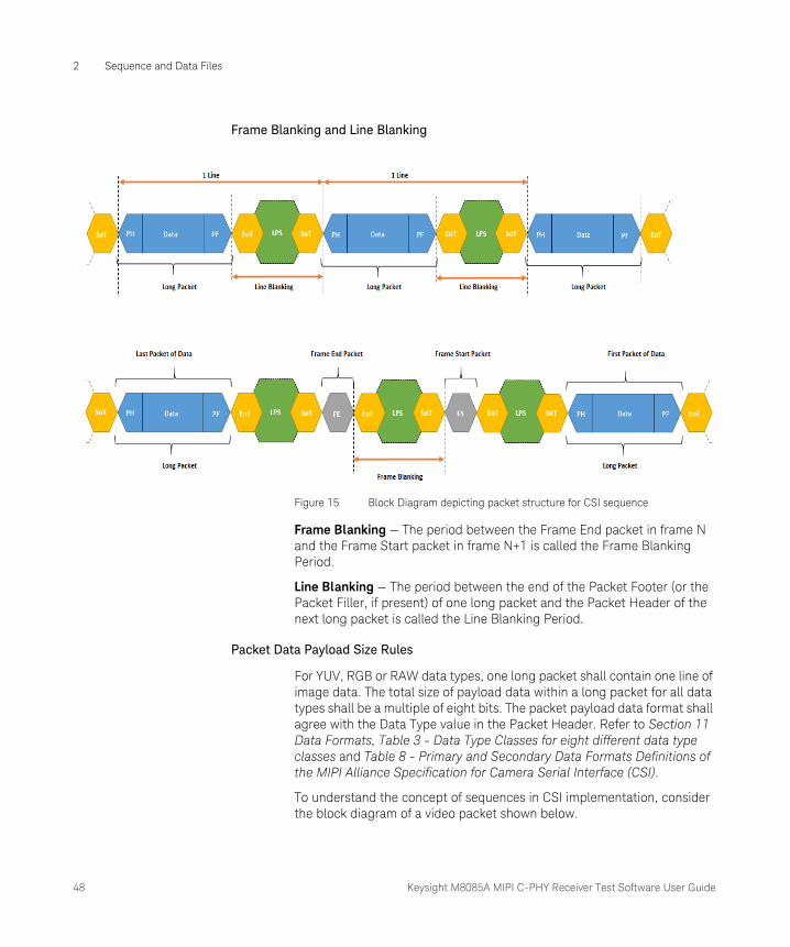
Figure 15 Block Diagram depicting packet structure for CSI sequence
Frame Blanking — The period between the Frame End packet in frame N and the Frame Start packet in frame N+1 is called the Frame Blanking Period.
Line Blanking — The period between the end of the Packet Footer (or the Packet Filler, if present) of one long packet and the Packet Header of the next long packet is called the Line Blanking Period.
Packet Data Payload Size Rules
For YUV, RGB or RAW data types, one long packet shall contain one line of image data. The total size of payload data within a long packet for all data types shall be a multiple of eight bits. The packet payload data format shall agree with the Data Type value in the Packet Header. Refer to Section 11 Data Formats, Table 3 - Data Type Classes for eight different data type classes and Table 8 - Primary and Secondary Data Formats Definitions of the MIPI Alliance Specification for Camera Serial Interface (CSI).
To understand the concept of sequences in CSI implementation, consider the block diagram of a video packet shown below.

Keysight M8085A MIPI C-PHY Receiver Test Software User Guide 49
Sequence and Data Files 2
Figure 16 Block Diagram of a CSI Video Frame
For each video line transmission, the short packet or the FrameStart (FS) indicates start of transmission of the video packet. The payload data, which is contained in a long packet, consists of the Packet Header (PH),

50 Keysight M8085A MIPI C-PHY Receiver Test Software User Guide
2 Sequence and Data Files
followed by the actual arbitrary data and ending with the Packet Footer (PF). Another short packet or the FrameEnd (FE) indicates the end of transmission of the video packet. This data burst is in an HS state.
A Line Blanking (LP state) is transmitted between each video line, that is, after the end of a Packet Footer (PF) till the beginning of the next Packet Header (PH).
A Frame Blanking (LP state) is transmitted between each video frame, that is, after the end of a FrameEnd (FE) till the beginning of the next FrameStart (FS) short packet.
Understanding a CSI sequence file
The description of the block diagram corroborates the structure of the CSI sequence file shown below, for CSI implementation. Note that all the text files defined in the sequence must be placed in the same folder directory where the sequence file is located.
HSFreq: 158 MBit/s;
Blocks:
FrameStart: B"FrameStart.txt",LP111E10880;
Blanking: LP111E10880;
Video: C1E"compliance640_480.txt",LP111E10880;
FrameEnd: B"FrameEnd.txt",LP111E2048;
Sequence:
1. FrameStart,1;
2. Blanking,1;
3. Video,480;
4. Blanking,2;
5. FrameEnd,1;
The sequence definition in the given example contains an intrinsic looping. In the sequence, the blanking lines generate the frame blanking, and the video lines contain the line blanking, which is generated by the LP states. The number of lines for the video data and the associated blanking is defined by the device manufacturer. The sequence begins with the
Keysight M8085A MIPI C-PHY Receiver Test Software User Guide 51
Sequence and Data Files 2
FrameStart block running once, followed by a Blanking line. Then, the Video block runs for 480 lines ending with another Blanking line, followed by the FrameEnd block running once. This sequence loops over until manually aborted.
If considered closely, the FrameStart block generates the Frame Start (FS) short packet, with the Frame Start Code 0x00 as its header. This follows an HS-LP transition using LP11 (or LP111 in C-PHY), where a line blanking is performed with an LPE marker, which fills the LP states until 10880 HS states are attained. The Blanking block generates a frame blanking packet of LP11 (or LP111 in C-PHY), which fills the LP states until 10880 HS states are attained and is generated to provide for the LP-HS transition before the actual video payload begins transmitting. In the Video block, the C-Macro with a 1-byte data type of 0x1E generates the Packet Header of the long packet, followed by the actual payload video data (in Hex format) in the compliance640_480.txt file.
Since the video data is High-Speed, the end of the video packet follows an HS to LP transition with a line blanking packet of LP11 (or LP111 in C-PHY), which fills the LP states until 10880 HS states are attained. Two blanking lines are sent to indicate the end of the video payload data and to save energy. The FrameEnd block generates the Frame End (FE) short packet, with the Frame End Code 0x01 as its header. This follows an HS-LP transition with a line blanking packet of LP11 (or LP111 in C-PHY), which fills the LP states until 2046 HS states are attained.
Some other points to note are:
• Since you cannot send more than one packet per burst, Blanking (LP state) is inserted at the end of each burst to avoid HS data from concatenating.
• The length of the line and frame blanking is device dependent.
• The data type 0x1E corresponds to the pixel color code YUV422 8-bit used in the video. Refer to Section 11 Data Formats of the MIPI Alliance Specification for Camera Serial Interface (CSI) for more information about the other Data Types for various color codes.
• The line blanking length and bits per pixel of a specific color code helps you in determining the total line length in HS states. The E-marker is used for the LP states instead of N, such that it fills up the blocks until the total defined length of HS States is attained.
NOTETo retain the same line rate for CSI implementation between D-PHY and C-PHY, it is recommended that you keep the number of HS states equal in the LP definition.
52 Keysight M8085A MIPI C-PHY Receiver Test Software User Guide
2 Sequence and Data Files
If all lines in a sequence file definition have an LPE statement in the end, you may calculate the Frame Rate:
1 Multiply the number of lines with the number defined in the LPE statement of the sequence file definition.
2 Repeat step 1 for all lanes in the frame and add the resulting values for each lane.
3 Multiply the sum of all lanes with the HS period length, which derives the Frame Rate.
Calculating HS Data Rate for CSI sequence
To calculate the minimum HS data rate required to run the sequence, you must be aware of at least the frame rate and the device’s display resolution, which is provided by the device manufacturer. The HS Frequency is the first line in the definition of a sequence file.
For example, let us consider that the device under test has a Frame Rate of 30 Hz and a display resolution of 640 x 480 pixels, where 640 is the horizontal resolution (or the length of each line) and 480 is the vertical resolution (or the number of video lines).
1 Calculate the line rate using the equation:
Line Rate = Frame Rate * Vertical Resolution
However, the number of video lines has certain number of blanking lines preceding and following the video data, which must be considered as well for data rate calculation. The equation for line rate is, therefore, modified to:
Line Rate = Frame Rate * (Vertical Resolution + no. of blanking lines)
Let us assume that there are 10 blanking lines in a frame.
In this case, Line Rate = 30 Hz * (480 + 10) = 14700 Hz
2 Determine the total length of lines in HS states.
i Determine the number of bits required for transmission of the video data. To do so, check the pixel color coding for the Data Type in the video. In this case, the pixel color code is YUV422, which uses 8-bit per pixel.
Total no. of bits per line = Bit-size per pixel * Horizontal resolution
In this case, Total no. of bits = 8 * 640 = 5120 bits per line.
ii The number of bits for video transmission is not sufficient for determining the total length of lines in HS states, since extra time is required for the LP states in the line blanking. Therefore,

Keysight M8085A MIPI C-PHY Receiver Test Software User Guide 53
Sequence and Data Files 2
you must consider the LP states and accordingly extend the bits per line. Considering these factors, a total length of 10880 lines in HS states can be safely used for calculation of the HS data rate.
3 Calculate the HS Data Rate using the equation:
Data Rate = Line Rate * Total length of lines in HS state
In this case, Data Rate = 14700 Hz x 10880 = 159.936 Mbps
Therefore, you can define the HS Data Rate (HSFreq) in the beginning of the sequence file, as shown in the example above.
For information on the CSI implementation in the D-PHY and C-PHY physical layer and detailed understanding of the protocol layer, refer to the MIPI Alliance Specification for Camera Serial Interface (CSI).
54 Keysight M8085A MIPI C-PHY Receiver Test Software User Guide
2 Sequence and Data Files
Sequence File Definition for DSI
Overview
DSI specifies the interface between a host processor and a peripheral such as a display module. It builds on existing MIPI Alliance specifications by adopting pixel formats and command set specified in DPI-2, DBI-489 2 and DCS standards. Some significant differences between DSI and CSI are:
• CSI uses unidirectional high-speed Link, whereas DSI is half-duplex bidirectional Link
• CSI makes use of a secondary channel, based on I2C, for control and status functions
• CSI data direction is from peripheral (Camera Module) to host processor, while DSI’s primary data direction is from host processor to peripheral (Display Module)
• CSI sequence file structure is different from that of the DSI sequence file structure. The former consists of only of the FrameStart and FrameEnd packet along with some blanking lines, whereas the latter consists of HSync, VSync and Blanking packages.
At the lowest level, DSI protocol specifies the sequence and value of bits and bytes traversing the interface. It specifies how bytes are organized into defined groups called packets. The protocol defines required headers for each packet, and how header information is generated and interpreted.
On the transmitter side of a DSI Link, parallel data, signal events, and commands are converted in the Protocol layer to packets, following the packet organization. The Protocol layer appends packet-protocol information and headers, and then sends complete bytes through the Lane Management layer to the PHY. Packets are serialized by the PHY and sent across the serial Link. The receiver side of a DSI Link performs the converse of the transmitter side, decomposing the packet into parallel data, signal events and commands.
If there are multiple Lanes, the Lane Management layer distributes bytes to separate PHYs, one PHY per Lane, as described in Section 6 of the MIPI Alliance Specification for Display Serial Interface (DSI). Packet protocol and formats are independent of the number of Lanes used. The DSI protocol permits multiple packets to be concatenated, which substantially boosts effective bandwidth. This is useful for events such as peripheral initialization, where many registers may be loaded with separate write commands at system startup. There are two modes of data transmission, HS and LP transmission modes, at the PHY layer. Before an HS transmission can be started, the transmitter PHY issues a SoT sequence to
Keysight M8085A MIPI C-PHY Receiver Test Software User Guide 55
Sequence and Data Files 2
the receiver. After that, data or command packets can be transmitted in HS mode. Multiple packets may exist within a single HS transmission and the end of transmission is always signaled at the PHY layer using a dedicated EoT sequence. To enhance the overall robustness of the system, DSI defines a dedicated EoT packet (EoTp) at the protocol layer for signaling the end of HS transmission. In HS mode, time gaps between packets shall result in separate HS transmissions for each packet, with a SoT, LPS, and EoT issued by the PHY layer between packets. This constraint does not apply to LP transmissions.
Long and Short Packet Formats
Two packet structures are defined for low-level protocol communication: Long packets and Short packets. For both packet structures, the Data Identifier (DI) is always the first byte of the packet, which includes information specifying the type of the packet.
Long Packet
A Long packet shall consist of three elements: a 32-bit Packet Header (PH), an application-specific Data Payload with a variable number of bytes, and a 16-bit Packet Footer (PF). The Packet Header is further composed of three elements: an 8-bit Data Identifier, a 16-bit Word Count, and 8-bit ECC. The Packet Footer has one element, a 16-bit checksum. Long packets can be from 6 to 65,541 bytes in length.
After the end of the Packet Header, the receiver reads the next Word Count multiplied by the bytes of the Data Payload.
Once the receiver has read the Data Payload it reads the Checksum in the Packet Footer. The host processor shall always calculate and transmit a Checksum in the Packet Footer. Peripherals are not required to calculate a Checksum. Also, note the special case of zero-byte Data Payload: if the payload has length 0, the Checksum calculation results in (0xFFFF). If the Checksum is not calculated, the Packet Footer shall consist of two bytes of all zeros (0x0000). In the generic case, the length of the Data Payload shall be a multiple of bytes. In addition, each data format may impose additional restrictions on the length of the payload data, e.g. multiple of four bytes.
Short Packet
A Short packet shall contain an 8-bit Data ID followed by two command or data bytes and an 8-bit ECC; a Packet Footer shall not be present. Short packets shall be four bytes in length. The Error Correction Code (ECC) byte allows single-bit errors to be corrected and 2-bit errors to be detected in the Short packet. Some short packets may also contain some data in the payload.
56 Keysight M8085A MIPI C-PHY Receiver Test Software User Guide
2 Sequence and Data Files
Long and Short packets have several common elements. The first byte of any packet is the DI (Data Identifier) byte. The Error Correction Code allows single-bit errors to be corrected and 2-bit errors to be detected in the Packet Header. The host processor shall always calculate and transmit an ECC byte. Peripherals shall support ECC in both forward- and reverse-direction communications.
DSI Sequence Format Description
Sync Event (H Start, H End, V Start, V End), Data Type = XX 0001 (0xX1)
Sync Events are Short packets and, therefore, can time-accurately represent events like the start and end of sync pulses. As “start” and “end” are separate and distinct events, the length of sync pulses, as well as position relative to active pixel data, e.g. front and back porch display timing, may be accurately conveyed to the peripheral. The Sync Events are defined as follows:
• Data Type = 00 0001 (0x01) V Sync Start
• Data Type = 01 0001 (0x11) V Sync End
• Data Type = 10 0001 (0x21) H Sync Start
• Data Type = 11 0001 (0x31) H Sync End
To represent timing information as accurately as possible a V Sync Start event represents the start of the VSA. It also implies an H Sync Start event for the first line of the VSA. Similarly, a V Sync End event implies an H Sync Start event for the last line of the VSA.
Sync events should occur in pairs, Sync Start and Sync End, if accurate pulse-length information must be conveyed. Alternatively, if only a single point (event) in time is required, a single sync event (normally, Sync Start) may be transmitted to the peripheral. Sync events may be concatenated with blanking packets to convey inter-line timing accurately and avoid the overhead of switching between LPS and HS for every event. Display modules that do not need traditional sync/blanking/pixel timing should transmit pixel data in a high-speed burst then put the bus in Low Power Mode, for reduced power consumption.
EoTp, Data Type = 00 1000 (0x08)
This short packet is used for indicating the end of a HS transmission to the data link layer. Therefore, detection of the end of HS transmission may be decoupled from physical layer characteristics. The main objective of the EoTp is to enhance overall robustness of the system during HS transmission mode. Therefore, DSI transmitters should not generate an EoTp when transmitting in LP mode. The Data Link layer of DSI receivers
Keysight M8085A MIPI C-PHY Receiver Test Software User Guide 57
Sequence and Data Files 2
shall detect and interpret arriving EoTps regardless of transmission mode (HS or LP modes) to decouple itself from the physical layer. Unlike other DSI packets, an EoTp has a fixed format as follows:
• Data Type = DI [5:0] = 0b001000
• Virtual Channel = DI [7:6] = 0b00
• Payload Data [15:0] = 0x0F0F
• ECC [7:0] = 0x01
Blanking Packet (Long), Data Type = 01 1001 (0x19)
A Blanking packet is used to convey blanking timing information in a Long packet. Normally, the packet represents a period between active scan lines of a Video Mode display, where traditional display timing is provided from the host processor to the display module. The blanking period may have Sync Event packets interspersed between blanking segments. Like all packets, the Blanking packet contents shall be an integer number of bytes. Blanking packets may contain arbitrary data as payload.
The Blanking packet consists of the DI byte, a two-byte WC, an ECC byte, a payload of length WC bytes, and a two-byte checksum.
Packed Pixel Stream, 16-bit Format, Long Packet, Data Type 00 1110 (0x0E)
This long packet (shown in the sequence example) is used to transmit image data formatted as 16-bit pixels to a Video Mode display module. The packet consists of the DI byte, a two-byte WC, an ECC byte, a payload of length WC bytes and a two-byte checksum.
Packet Header Error Detection/Correction
The host processor in a DSI-based system shall generate an error-correction code (ECC) and append it to the header of every packet sent to the peripheral. The ECC takes the form of a single byte following the header bytes. The ECC byte shall provide single-bit error correction and 2-bit error detection for the entire Packet Header.
Checksum Generation for Long Packet Payloads
Long packets are comprised of a Packet Header protected by an ECC byte and a payload of 0 to 216-1 bytes. To detect errors in transmission of Long packets, a checksum is calculated over the payload portion of the data packet. Note that, for the special case of a zero-length payload, the 2-byte checksum is set to 0xFFFF.

58 Keysight M8085A MIPI C-PHY Receiver Test Software User Guide
2 Sequence and Data Files
Checksum generation and transmission is mandatory for host processors sending Long packets to peripherals. It is optional for peripherals transmitting Long packets to the host processor. However, the format of Long packets is fixed; peripherals that do not support checksum generation shall transmit two bytes having value 0x0000 in place of the checksum bytes when sending Long packets to the host processor. The host processor shall disable checksum checking for received Long packets from peripherals that do not support checksum generation.
Transmission Packet Sequences
DSI supports several formats, or packet sequences, for Video Mode data transmission. The peripheral’s timing requirements dictate which format is appropriate. In the following sections, Burst Mode refers to time-compression of the RGB pixel (active video) portion of the transmission.
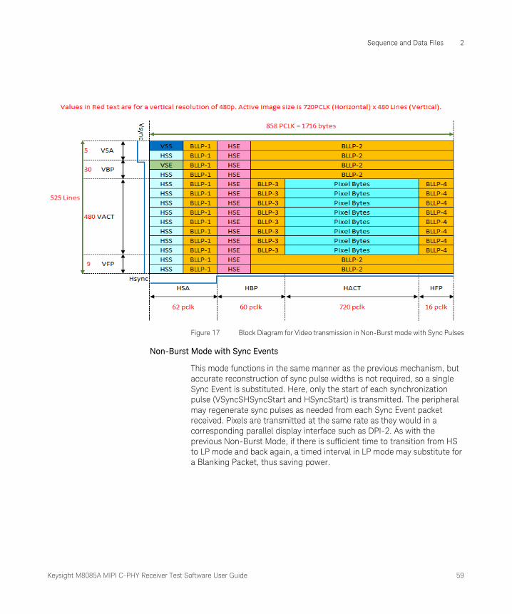
Non-Burst Mode with Sync Pulses
This mode enables the peripheral to accurately reconstruct original video timing, including sync pulse widths. Normally, periods shown as HSA (Horizontal Sync Active), HBP (Horizontal Back Porch) and HFP (Horizontal Front Porch) are filled by Blanking Packets, with lengths (including packet overhead) calculated to match the period specified by the peripheral’s data sheet. Alternatively, if there is sufficient time to transition from HS to LP mode and back again, a timed interval in LP mode may substitute for a Blanking Packet, thus saving power. During HSA, HBP and HFP periods, the bus should stay in the LP-11 state.
NOTEAn ECC byte can be applied to both Short and Long packets. Checksum bytes shall only be applied to Long packets.
Keysight M8085A MIPI C-PHY Receiver Test Software User Guide 59
Sequence and Data Files 2
Figure 17 Block Diagram for Video transmission in Non-Burst mode with Sync Pulses
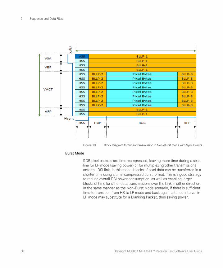
Non-Burst Mode with Sync Events
This mode functions in the same manner as the previous mechanism, but accurate reconstruction of sync pulse widths is not required, so a single Sync Event is substituted. Here, only the start of each synchronization pulse (VSyncSHSyncStart and HSyncStart) is transmitted. The peripheral may regenerate sync pulses as needed from each Sync Event packet received. Pixels are transmitted at the same rate as they would in a corresponding parallel display interface such as DPI-2. As with the previous Non-Burst Mode, if there is sufficient time to transition from HS to LP mode and back again, a timed interval in LP mode may substitute for a Blanking Packet, thus saving power.
60 Keysight M8085A MIPI C-PHY Receiver Test Software User Guide
2 Sequence and Data Files
Figure 18 Block Diagram for Video transmission in Non-Burst mode with Sync Events
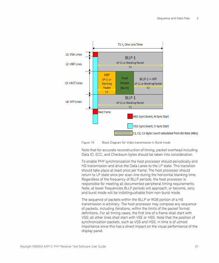
Burst Mode
RGB pixel packets are time-compressed, leaving more time during a scan line for LP mode (saving power) or for multiplexing other transmissions onto the DSI link. In this mode, blocks of pixel data can be transferred in a shorter time using a time-compressed burst format. This is a good strategy to reduce overall DSI power consumption, as well as enabling larger blocks of time for other data transmissions over the Link in either direction. In the same manner as the Non-Burst Mode scenario, if there is sufficient time to transition from HS to LP mode and back again, a timed interval in LP mode may substitute for a Blanking Packet, thus saving power.
Keysight M8085A MIPI C-PHY Receiver Test Software User Guide 61
Sequence and Data Files 2
Figure 19 Block Diagram for Video transmission in Burst mode
Note that for accurate reconstruction of timing, packet overhead including Data ID, ECC, and Checksum bytes should be taken into consideration.
To enable PHY synchronization the host processor should periodically end HS transmission and drive the Data Lanes to the LP state. This transition should take place at least once per frame; The host processor should return to LP state once per scan-line during the horizontal blanking time. Regardless of the frequency of BLLP periods, the host processor is responsible for meeting all documented peripheral timing requirements. Note, at lower frequencies BLLP periods will approach, or become, zero, and burst mode will be indistinguishable from non-burst mode.
The sequence of packets within the BLLP or RGB portion of a HS transmission is arbitrary. The host processor may compose any sequence of packets, including iterations, within the limits of the packet format definitions. For all timing cases, the first line of a frame shall start with VSS; all other lines shall start with VSE or HSS. Note that the position of synchronization packets, such as VSS and HSS, in time is of utmost importance since this has a direct impact on the visual performance of the display panel.
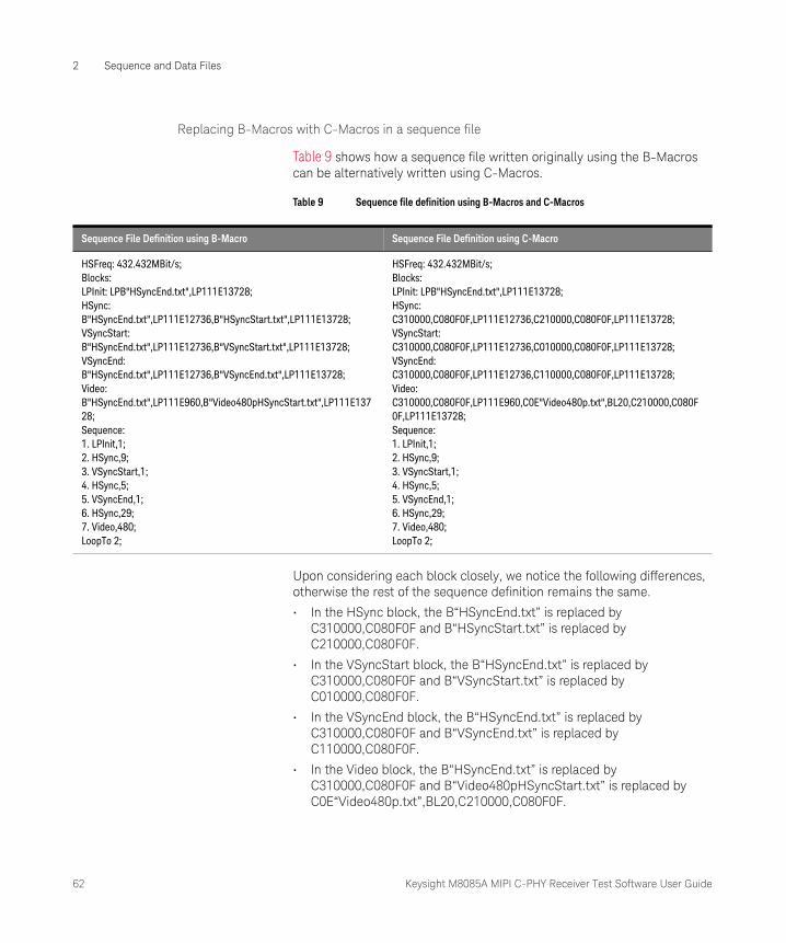
62 Keysight M8085A MIPI C-PHY Receiver Test Software User Guide
2 Sequence and Data Files
Replacing B-Macros with C-Macros in a sequence file
Table 9 shows how a sequence file written originally using the B-Macros can be alternatively written using C-Macros.
Table 9 Sequence file definition using B-Macros and C-Macros
Upon considering each block closely, we notice the following differences, otherwise the rest of the sequence definition remains the same.
• In the HSync block, the B“HSyncEnd.txt” is replaced by C310000,C080F0F and B“HSyncStart.txt” is replaced by C210000,C080F0F.
• In the VSyncStart block, the B“HSyncEnd.txt” is replaced by C310000,C080F0F and B“VSyncStart.txt” is replaced by C010000,C080F0F.
• In the VSyncEnd block, the B“HSyncEnd.txt” is replaced by C310000,C080F0F and B“VSyncEnd.txt” is replaced by C110000,C080F0F.
• In the Video block, the B“HSyncEnd.txt” is replaced by C310000,C080F0F and B“Video480pHSyncStart.txt” is replaced by C0E“Video480p.txt”,BL20,C210000,C080F0F.
Sequence File Definition using B-Macro Sequence File Definition using C-Macro
HSFreq: 432.432MBit/s; Blocks:LPInit: LPB"HSyncEnd.txt",LP111E13728;HSync: B"HSyncEnd.txt",LP111E12736,B"HSyncStart.txt",LP111E13728;VSyncStart: B"HSyncEnd.txt",LP111E12736,B"VSyncStart.txt",LP111E13728;VSyncEnd: B"HSyncEnd.txt",LP111E12736,B"VSyncEnd.txt",LP111E13728;Video: B"HSyncEnd.txt",LP111E960,B"Video480pHSyncStart.txt",LP111E13728;Sequence:1. LPInit,1;2. HSync,9;3. VSyncStart,1;4. HSync,5;5. VSyncEnd,1;6. HSync,29;7. Video,480;LoopTo 2;
HSFreq: 432.432MBit/s; Blocks:LPInit: LPB"HSyncEnd.txt",LP111E13728;HSync: C310000,C080F0F,LP111E12736,C210000,C080F0F,LP111E13728;VSyncStart: C310000,C080F0F,LP111E12736,C010000,C080F0F,LP111E13728;VSyncEnd: C310000,C080F0F,LP111E12736,C110000,C080F0F,LP111E13728;Video: C310000,C080F0F,LP111E960,C0E"Video480p.txt",BL20,C210000,C080F0F,LP111E13728;Sequence:1. LPInit,1;2. HSync,9;3. VSyncStart,1;4. HSync,5;5. VSyncEnd,1;6. HSync,29;7. Video,480;LoopTo 2;
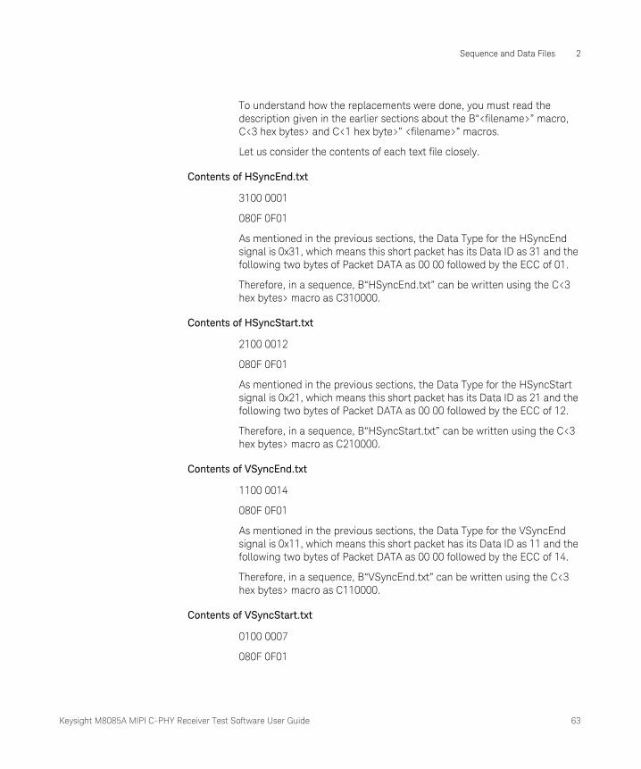
Keysight M8085A MIPI C-PHY Receiver Test Software User Guide 63
Sequence and Data Files 2
To understand how the replacements were done, you must read the description given in the earlier sections about the B“<filename>” macro, C<3 hex bytes> and C<1 hex byte>” <filename>” macros.
Let us consider the contents of each text file closely.
Contents of HSyncEnd.txt
3100 0001
080F 0F01
As mentioned in the previous sections, the Data Type for the HSyncEnd signal is 0x31, which means this short packet has its Data ID as 31 and the following two bytes of Packet DATA as 00 00 followed by the ECC of 01.
Therefore, in a sequence, B“HSyncEnd.txt” can be written using the C<3 hex bytes> macro as C310000.
Contents of HSyncStart.txt
2100 0012
080F 0F01
As mentioned in the previous sections, the Data Type for the HSyncStart signal is 0x21, which means this short packet has its Data ID as 21 and the following two bytes of Packet DATA as 00 00 followed by the ECC of 12.
Therefore, in a sequence, B“HSyncStart.txt” can be written using the C<3 hex bytes> macro as C210000.
Contents of VSyncEnd.txt
1100 0014
080F 0F01
As mentioned in the previous sections, the Data Type for the VSyncEnd signal is 0x11, which means this short packet has its Data ID as 11 and the following two bytes of Packet DATA as 00 00 followed by the ECC of 14.
Therefore, in a sequence, B“VSyncEnd.txt” can be written using the C<3 hex bytes> macro as C110000.
Contents of VSyncStart.txt
0100 0007
080F 0F01

64 Keysight M8085A MIPI C-PHY Receiver Test Software User Guide
2 Sequence and Data Files
As mentioned in the previous sections, the Data Type for the VSyncStart signal is 0x01, which means this short packet has its Data ID as 01 and the following two bytes of Packet DATA as 00 00 followed by the ECC of 07.
Therefore, in a sequence, B“VSyncStart.txt” can be written using the C<3 hex bytes> macro as C010000.
Notice that within each text file considered so far, a hexadecimal value 080F 0F01 is mentioned. This is the EoT package, which is used at end of each HS transmission in a short packet. The EoT package has a fixed format with Data ID as 08, Payload Data as 0F0F and ECC of 01.
Therefore, at the end of each C<3 hex bytes> macro defined for the four files, you must add the C<3 hex bytes> macro for the EoT package as C080F0F, as shown in the sequence definition.
Contents of Video480pHSyncStart.txt
0EA0 0508
1084 1084
1084 1084
1084 1084
.
.
.
1084 1084
FA44 1914
001F 0000
0000 0000
0000 0000
0000 0000
0000 0000
0000 6F1D
2100 0012
080F 0F01
The elements of the actual video data in the file ‘Video480pHSyncStart.txt’ can be divided as follows:
Keysight M8085A MIPI C-PHY Receiver Test Software User Guide 65
Sequence and Data Files 2
• The header consists of Data ID: 0E followed by a two-byte word counter A005, followed by the ECC for that header data as 08.
• The actual video payload data starts from a hex value of 1084 and ends at a hex value of 1084. Note that the payload data is too long and has been truncated for documentation purpose.
• At the end of the payload, a two byte CRC is added, which is FA44.
• After the checksum, a Blanking packet is added to covey the blanking timing information in this video packet. This Blanking packet consists of the DI byte of 0x19, a two-byte Word Count of 1400, an ECC byte of 1F, a payload of 20 bytes, and a two-byte checksum of 6F1D. This blanking packet enables the HS-LP transition and corresponds to the HFP (Horizontal Front Porch) before the HSyncStart.
• In the end, a short packet in HS mode is generated, which has the HSyncStart data, which allows the HS-LP transition, before the device goes into a low power state.
Looking back at the Video block, the B“Video480pHSyncStart.txt” is replaced by C0E“Video480p.txt”,BL20,C210000,C080F0F, which indicates that only the actual payload data has been extracted into another text file named Video480p.txt and the rest of the data is appended using the C-Macro to the beginning and to the end of the payload data file. Notice that the Blanking packet with Data ID 0x19, which was part of the initial payload data, has been rewritten using the BL<number of blanking bytes> macros as BL20.
Irrespective of whether you use the B-Macros or the C-Macros, you must ensure that the data is defined in the correct order and you can use the sequence file in either format for waveform generation in the plug-in.
Notice that there has been no change made to the LPInit block of the sequence file, even though the HSyncEnd.txt file is used. This is because even though the HSyncEnd.txt contains hexadecimal data for HS mode, the LPB“filename” macro is used for generating Low Power data specified in the file HSyncEnd.txt, such that the display device is powered on.
To know more about the Data Types required to construct the short or long packets or to define C-Macros in a sequence file, refer to the MIPI Alliance Specification for Display Serial Interface.
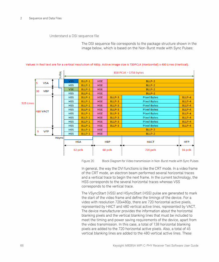
66 Keysight M8085A MIPI C-PHY Receiver Test Software User Guide
2 Sequence and Data Files
Understand a DSI sequence file
The DSI sequence file corresponds to the package structure shown in the image below, which is based on the Non-Burst mode with Sync Pulses:
Figure 20 Block Diagram for Video transmission in Non-Burst mode with Sync Pulses
In general, the way the DVI functions is like the CRT mode. In a video frame of the CRT mode, an electron beam performed several horizontal traces and a vertical trace to begin the next frame. In the current technology, the HSS corresponds to the several horizontal traces whereas VSS corresponds to the vertical trace.
The VSyncStart (VSS) and HSyncStart (HSS) pulse are generated to mark the start of the video frame and define the timings of the device. For a video with resolution 720x480p, there are 720 horizontal active pixels, represented by HACT and 480 vertical active lines, represented by VACT. The device manufacturer provides the information about the horizontal blanking pixels and the vertical blanking lines that must be included to meet the timing and power saving requirements of the device, apart from the video transmission. In this case, a total of 138 horizontal blanking pixels are added to the 720 horizontal active pixels. Also, a total of 45 vertical blanking lines are added to the 480 vertical active lines. These

Keysight M8085A MIPI C-PHY Receiver Test Software User Guide 67
Sequence and Data Files 2
HSync and VSync data is required for proper synchronization of the video data and to achieve proper timing in displaying the video data and is represented by HSyncActive (HSA) and VSyncActive (VSA), respectively. As described earlier, HSS, HSE, VSS and VSE are short packets containing High Speed data and blanking header information. They are part of the HSA and VSA.
Sync events are introduced such that only HSS have to be added. In this case, where Sync pulses are used, Blanking Lines can be added, which may be HS or LP, depending on the timing set between HSS and HSE.
The Horizontal Back Porch (HBP), Horizontal Front Porch (HFP), Vertical Back Porch (VBP), Vertical Front Porch (VFP) are indicated by BLLPs. The Blanking or Low-Power Interval (BLLP) is defined as a period during which video packets such as pixel-stream and sync event packets are not actively transmitted to the peripheral. The BLLP provides for the HS-LP and LP-HS transition when the device is powered on, during the switch to video mode and to save the device's power either in the idle state or just before the start of the video data. In this image, the HBP and HFP are indicated by BLLP-3 and BLLP-4, respectively whereas VBP and VFP are indicated by BLLP-1 and BLLP-2, respectively.
Now, let us consider the example given below of a sequence file for DSI implementation, derived from the video package displayed in the image above.
HSFreq: 432.432MBit/s;
Blocks:
LPInit: LPB"HSyncEnd.txt",LP111E13728;
HSync: C310000,C080F0F,LP111E12736,C210000,C080F0F,LP111E13728;
VSyncStart: C310000,C080F0F,LP111E12736,C010000,C080F0F,LP111E13728;
VSyncEnd: C310000,C080F0F,LP111E12736,C110000,C080F0F,LP111E13728;
Video: C310000,C080F0F,LP11E960,C0E"Video480p.txt",BL20,C210000,C080F0F,LP111E13728;
Sequence:
1. LPInit,1;
2. HSync,9;
3. VSyncStart,1;
4. HSync,5;
68 Keysight M8085A MIPI C-PHY Receiver Test Software User Guide
2 Sequence and Data Files
5. VSyncEnd,1;
6. HSync,29;
7. Video,480;
LoopTo 2;
The LPInit block generates the HsyncEnd signal is a low power mode to power on the display device.
To achieve proper synchronization and timing for the video data, the HSync and VSync signals are used. The number of vertical blanking lines and horizontal blanking pixels are provided by the device manufacturer.
The HSync block, which loops over for 9 lines, generates the HSE signal, indicated by C310000,C080F0F before the device switches to low power mode until 12736 HS states are attained. The LP111E12736 corresponds to BLLP-2 on the image. Then, HSS signal is generated, indicated by C210000,C080F0F, after which the device enters into low power mode again until 13728 HS states are attained. The LP111E13728 corresponds to BLLP-1 on the image.
The VSyncStart block, which loops over once, generates the HSE signal followed by LP111E12736 state. Then, VSS signal is generated, indicated by C010000,C080F0F, after which the device enters into low power mode again until 13728 HS states are attained.
The HSync block loops over for 5 lines again before the VSyncEnd block loops over once. The VSyncEnd block generates the HSE signal followed by LP11E12736 state. Then, VSE signal is generated, indicated by C110000,C080F0F, after which the device enters into low power mode again until 13728 HS states are attained.
The HSync block loops over for 29 lines again before the Video block loops over for 480 lines. In the Video block, the HSE signal is generated followed by LP111E960 state. Here, in the duration between the Video line and HSyncEnd, there is a short LP state to allow the device to save power before the video starts. LP111E960, which forms the HBP, allows device to save power before switching to video mode. C0E“Video480p.txt” indicates the header information followed by the active payload data contained in the “Video480p.txt” file. The Video block displays BL20, which forms the HFP, before the HSS is generated again followed by switching into low power mode until 13728 HS states are attained.
Note that BLLP-1 and BLLP-2, that is, LP111E12736 and LP111E13728 are blanking lines. Instead of sending video data, long LP states are generated. The total number of HS states is driven by the E marker, which

Keysight M8085A MIPI C-PHY Receiver Test Software User Guide 69
Sequence and Data Files 2
means each line has a fixed duration, depending on the data rate. It includes the HS states before the LPE marker is defined and the time taken to switch to the HS mode.
You must always ensure that to define a proper sequence, each block must end with the same HS or LP state to avoid any unexpected loops.
Calculating HS Data Rate for the DSI sequence
To calculate the minimum HS data rate required to run the sequence, you must be aware of at least the frame rate, the Blanking Lines (HBlank and VBlank) and the device’s display resolution, in other words, the pixels per line and lines per frame, which are provided by the device manufacturer. The HS Frequency is the first line in the definition of a sequence file.
For example, let us consider that the device under test has a Frame Rate of 60 Hz and a display resolution of 640 x 480 pixels, where 640 is the horizontal resolution (or the length of each line) and 480 is the vertical resolution (or the number of video lines). The number of header (blanking lines) is given as 45.
1 Calculate the total no. of lines using the equation:
Total Lines = Video Lines + Header (Blanking) lines = 480 + 45 = 525 lines
2 Calculate the Line Rate using the equation:
Line Rate = Frame Rate * Total Lines = 60 Hz x 525 lines = 31.5 kHz
3 Calculate the No. of pixels per line using the equation:
No. of pixels per line = HBlanking + Horizontal Resolution
where, the HBlanking data is given by the device manufacturer. Let us assume 160 HBlanking lines.
Therefore, No. of pixels per line = 160 + 640 = 800 pixels per line.
4 Determine the number of bits required for transmission of the video data. To do so, check the pixel color coding for the Data Type in the video from the device’s specification. In this case, the pixel color code is RGB, which uses 24-bits per pixel.
Calculate the total no. of bits per line using the equation:
Total no. of bits per line = Bit-size per pixel * No. of pixels per line
In this case, Total no. of bits per line = 24 * 800 = 19.2 kbits per line
5 Calculate the HS Data Rate using the equation:
Data Rate = Line Rate * Total no. of bits per line
In this case, Data Rate = 31.5 kHz * 19.2 kbits per line = 604.8 Mbps
70 Keysight M8085A MIPI C-PHY Receiver Test Software User Guide
2 Sequence and Data Files
Therefore, for a VGA mode video with a frame rate of 60 Hz, you must set a data rate of 604.8 Mbps, which you can define as HSFreq in the beginning of the sequence file.
For information on the DSI implementation in the D-PHY and C-PHY physical layer and detailed understanding of the protocol layer, refer to the MIPI Alliance Specification for Display Serial Interface.
Keysight M8085A MIPI C-PHY Receiver Test Software
User Guide
3 Results Description and Procedure Parameters
Result Description / 72MIPI C-PHY Receiver Test Software Procedure Parameters / 73
CAUTIONBefore running the calibration or test procedures, ensure that the system connections are done properly with the necessary equipment. You may run the calibration and test procedures in Offline mode, that is, without any instrument connected. However, the Offline mode is intended for product demonstrations with simulated data only. Calibration procedures that are run in Offline mode do not generate valid calibration data.
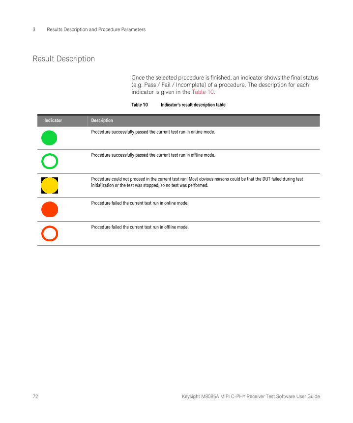
72 Keysight M8085A MIPI C-PHY Receiver Test Software User Guide
3 Results Description and Procedure Parameters
Result Description
Once the selected procedure is finished, an indicator shows the final status (e.g. Pass / Fail / Incomplete) of a procedure. The description for each indicator is given in the Table 10.
Table 10 Indicator's result description table
Ind icator Description
Procedure successfully passed the current test run in online mode.
Procedure successfully passed the current test run in offline mode.
Procedure could not proceed in the current test run. Most obvious reasons could be that the DUT failed during test initialization or the test was stopped, so no test was performed.
Procedure failed the current test run in online mode.
Procedure failed the current test run in offline mode.
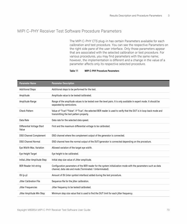
Keysight M8085A MIPI C-PHY Receiver Test Software User Guide 73
Results Description and Procedure Parameters 3
MIPI C-PHY Receiver Test Software Procedure Parameters
The MIPI C-PHY CTS plug-in has certain Parameters available for each calibration and test procedure. You can see the respective Parameters on the right side pane of the user interface. Only those parameters appear that are associated with the selected calibration or test procedure. For various procedures, you may find parameters with the same name; however, the implementation is different and a change in the value of a parameter affects only its respective selected procedure.
Table 11 MIPI C-PHY Procedure Parameters
Parameter Name Parameter Description
Additional Steps Additional steps to be performed for the test.
Amplitude Amplitude value to be tested/calibrated.
Amplitude Range Range of the amplitude values to be tested over the level pairs. It is only available in expert mode. It should be separated by semicolons.
Check Pattern Value of “True”/”False”. If “True”, the selected BER reader is used to verify that the DUT is in loop-back mode and transmitting the test pattern properly.
Data Rate Data rate for the selected data speed.
Differential Voltage Start Value
First and the maximum differential voltage to be calibrated.
DSO Channel Complement DSO channel where the complement output of the generator is connected.
DSO Channel Normal DSO channel here the normal output of the DUT/generator is connected depending on the procedure.
Eye Width Max. Variation Allowed variation of the target eye width.
Eye Height Target Eye height to be calibrated.
Initial Jitter Amplitude Step Initial step size value of Jitter amplitude.
BER Reader Init string Configuration parameters of the BER reader for the system initialization mode with the parameters such as data channel, data rate and mode (Terminated / Unterminated).
ISI (p-p) Amount of ISI (inter symbol interface) added during the test procedure.
Jitter Calibration File Sequence file for the jitter calibration.
Jitter Frequencies Jitter frequency to be tested/calibrated.
Jitter Amplitude Min Step Minimum step size value that is used to find the DUT limit for each jitter frequency.
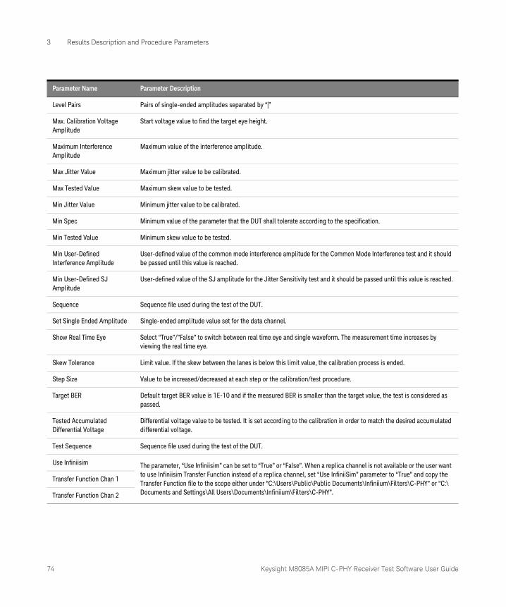
74 Keysight M8085A MIPI C-PHY Receiver Test Software User Guide
3 Results Description and Procedure Parameters
Level Pairs Pairs of single-ended amplitudes separated by “|”
Max. Calibration Voltage Amplitude
Start voltage value to find the target eye height.
Maximum Interference Amplitude
Maximum value of the interference amplitude.
Max Jitter Value Maximum jitter value to be calibrated.
Max Tested Value Maximum skew value to be tested.
Min Jitter Value Minimum jitter value to be calibrated.
Min Spec Minimum value of the parameter that the DUT shall tolerate according to the specification.
Min Tested Value Minimum skew value to be tested.
Min User-Defined Interference Amplitude
User-defined value of the common mode interference amplitude for the Common Mode Interference test and it should be passed until this value is reached.
Min User-Defined SJ Amplitude
User-defined value of the SJ amplitude for the Jitter Sensitivity test and it should be passed until this value is reached.
Sequence Sequence file used during the test of the DUT.
Set Single Ended Amplitude Single-ended amplitude value set for the data channel.
Show Real Time Eye Select “True”/”False” to switch between real time eye and single waveform. The measurement time increases by viewing the real time eye.
Skew Tolerance Limit value. If the skew between the lanes is below this limit value, the calibration process is ended.
Step Size Value to be increased/decreased at each step or the calibration/test procedure.
Target BER Default target BER value is 1E-10 and if the measured BER is smaller than the target value, the test is considered as passed.
Tested Accumulated Differential Voltage
Differential voltage value to be tested. It is set according to the calibration in order to match the desired accumulated differential voltage.
Test Sequence Sequence file used during the test of the DUT.
Use Infiniisim The parameter, “Use Infiniisim” can be set to “True” or “False”. When a replica channel is not available or the user want to use Infiniisim Transfer Function instead of a replica channel, set “Use InfiniiSim” parameter to “True” and copy the Transfer Function file to the scope either under “C:\Users\Public\Public Documents\Infiniium\Filters\C-PHY” or “C:\Documents and Settings\All Users\Documents\Infiniium\Filters\C-PHY”.
Transfer Function Chan 1
Transfer Function Chan 2
Parameter Name Parameter Description
Keysight M8085A MIPI C-PHY Receiver Test Software
User Guide
4 Calibrations and Test Procedures
Connections and Probing Methods / 76Calibration Procedures / 78
CAUTIONBefore running the calibration or test procedures, ensure that the system connections are done properly with the necessary equipment. You may run the calibration and test procedures in Offline mode, that is, without any instrument connected. However, the Offline mode is intended for product demonstrations with simulated data only. Calibration procedures that are run in Offline mode do not generate valid calibration data.
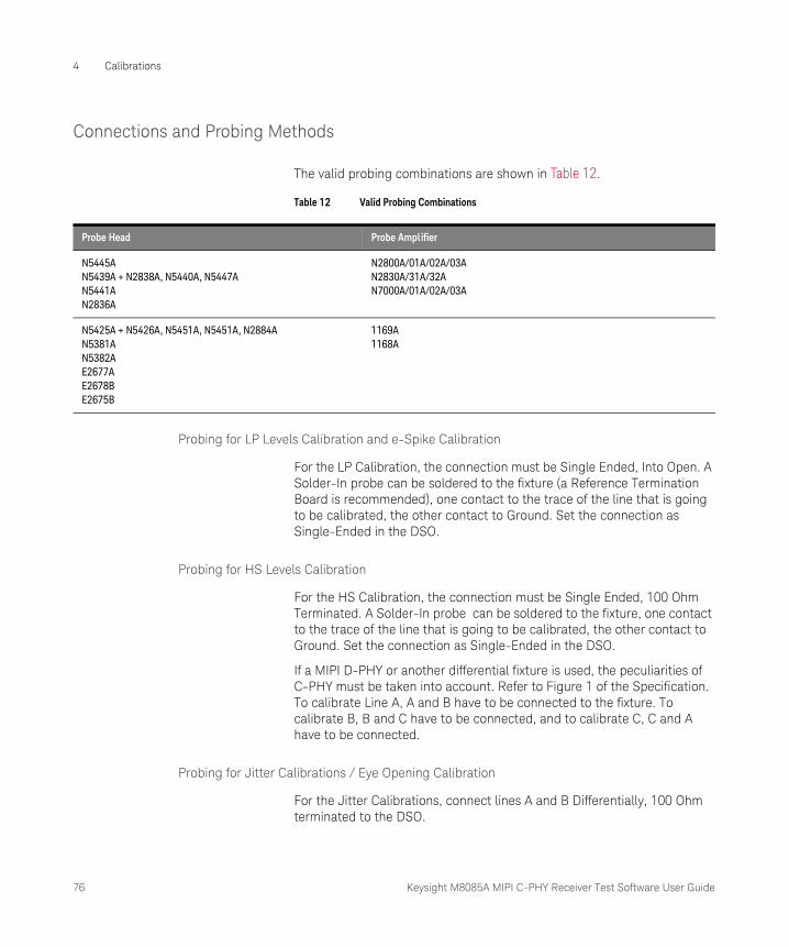
76 Keysight M8085A MIPI C-PHY Receiver Test Software User Guide
4 Calibrations
Connections and Probing Methods
The valid probing combinations are shown in Table 12.
Table 12 Valid Probing Combinations
Probing for LP Levels Calibration and e-Spike Calibration
For the LP Calibration, the connection must be Single Ended, Into Open. A Solder-In probe can be soldered to the fixture (a Reference Termination Board is recommended), one contact to the trace of the line that is going to be calibrated, the other contact to Ground. Set the connection as Single-Ended in the DSO.
Probing for HS Levels Calibration
For the HS Calibration, the connection must be Single Ended, 100 Ohm Terminated. A Solder-In probe can be soldered to the fixture, one contact to the trace of the line that is going to be calibrated, the other contact to Ground. Set the connection as Single-Ended in the DSO.
If a MIPI D-PHY or another differential fixture is used, the peculiarities of C-PHY must be taken into account. Refer to Figure 1 of the Specification. To calibrate Line A, A and B have to be connected to the fixture. To calibrate B, B and C have to be connected, and to calibrate C, C and A have to be connected.
Probing for Jitter Calibrations / Eye Opening Calibration
For the Jitter Calibrations, connect lines A and B Differentially, 100 Ohm terminated to the DSO.
Probe Head Probe Amplifier
N5445AN5439A + N2838A, N5440A, N5447AN5441AN2836A
N2800A/01A/02A/03AN2830A/31A/32AN7000A/01A/02A/03A
N5425A + N5426A, N5451A, N5451A, N2884AN5381AN5382AE2677AE2678BE2675B
1169A1168A
Keysight M8085A MIPI C-PHY Receiver Test Software User Guide 77
Calibrations 4
The following are the two ways to achieve this:
1 Use probes as in shown in Table 12 on page 76. Instead of probing Single Ended, in the line that is being calibrated and GND, probe differentially in lines A and B. A 100 Ohm termination is required in the fixture.
2 Connect the outputs of the AWG lines A and B differentially to the scope, using an N5380B differential probe head + 1169A/1168A probe amplifier, leaving the middle pin open. Alternatively, a combination of N5444A and compatible probe amplifier may be used.
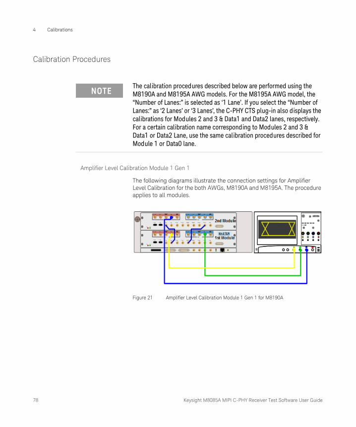
78 Keysight M8085A MIPI C-PHY Receiver Test Software User Guide
4 Calibrations
Calibration Procedures
Amplifier Level Calibration Module 1 Gen 1
The following diagrams illustrate the connection settings for Amplifier Level Calibration for the both AWGs, M8190A and M8195A. The procedure applies to all modules.
Figure 21 Amplifier Level Calibration Module 1 Gen 1 for M8190A
NOTEThe calibration procedures described below are performed using the M8190A and M8195A AWG models. For the M8195A AWG model, the “Number of Lanes:” is selected as ‘1 Lane’. If you select the “Number of Lanes:” as ‘2 Lanes’ or ‘3 Lanes’, the C-PHY CTS plug-in also displays the calibrations for Modules 2 and 3 & Data1 and Data2 lanes, respectively. For a certain calibration name corresponding to Modules 2 and 3 & Data1 or Data2 Lane, use the same calibration procedures described for Module 1 or Data0 lane.
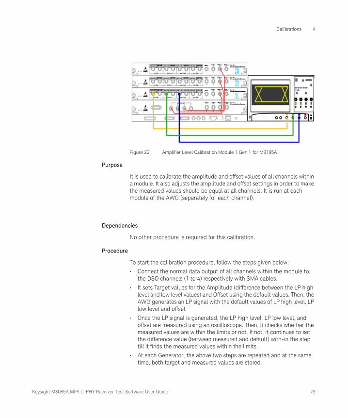
Keysight M8085A MIPI C-PHY Receiver Test Software User Guide 79
Calibrations 4
Figure 22 Amplifier Level Calibration Module 1 Gen 1 for M8195A
Purpose
It is used to calibrate the amplitude and offset values of all channels within a module. It also adjusts the amplitude and offset settings in order to make the measured values should be equal at all channels. It is run at each module of the AWG (separately for each channel).
Dependencies
No other procedure is required for this calibration.
Procedure
To start the calibration procedure, follow the steps given below:
• Connect the normal data output of all channels within the module to the DSO channels (1 to 4) respectively with SMA cables.
• It sets Target values for the Amplitude (difference between the LP high level and low level values) and Offset using the default values. Then, the AWG generates an LP signal with the default values of LP high level, LP low level and offset
• Once the LP signal is generated, the LP high level, LP low level, and offset are measured using an oscilloscope. Then, it checks whether the measured values are within the limits or not. If not, it continues to set the difference value (between measured and default) with-in the step till it finds the measured values within the limits
• At each Generator, the above two steps are repeated and at the same time, both target and measured values are stored.
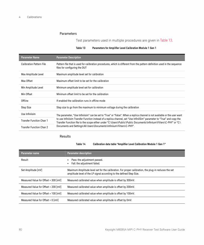
80 Keysight M8085A MIPI C-PHY Receiver Test Software User Guide
4 Calibrations
Parameters
Test parameters used in multiple procedures are given in Table 13.
Table 13 Parameters for Amplifier Level Calibration Module 1 Gen 1
Results
Table 14 Calibration data table “Amplifier Level Calibration Module 1 Gen 1”
Parameter Name Parameter Description
Calibration Pattern File Pattern file that is used for calibration procedures, which is different from the pattern definition used in the sequence files for configuring the DUT
Max Amplitude Level Maximum amplitude level set for calibration
Max Offset Maximum offset limit to be set for the calibration
Min Amplitude Level Minimum amplitude level set for calibration
Min Offset Minimum offset limit to be set for the calibration
Offline If enabled the calibration runs in offline mode
Step Size Step size to go from the maximum to minimum voltage during the calibration
Use Infiniisim The parameter, “Use Infiniisim” can be set to “True” or “False”. When a replica channel is not available or the user want to use Infiniisim Transfer Function instead of a replica channel, set “Use InfiniiSim” parameter to “True” and copy the Transfer Function file to the scope either under “C:\Users\Public\Public Documents\Infiniium\Filters\C-PHY” or “C:\Documents and Settings\All Users\Documents\Infiniium\Filters\C-PHY”.
Transfer Function Chan 1
Transfer Function Chan 2
Parameter name Parameter description
Result • Pass: the adjustment passed.• Fail: the adjustment failed.
Set Amplitude [mV] Maximum Amplitude level set for the calibration. For proper calibration, the plug-in reduces the set amplitude level of the LP signal according to the defined Step Size.
Measured Value for Offset = 300 [mV] Measured calibrated value when amplitude is offset by 300mV.
Measured Value for Offset = 200 [mV] Measured calibrated value when amplitude is offset by 200mV.
Measured Value for Offset = 100 [mV] Measured calibrated value when amplitude is offset by 100mV.
Measured Value for Offset = 0 [mV] Measured calibrated value when amplitude is offset by 0mV.
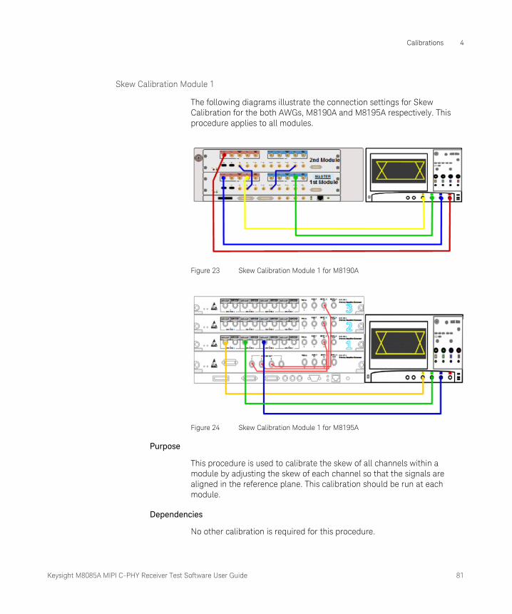
Keysight M8085A MIPI C-PHY Receiver Test Software User Guide 81
Calibrations 4
Skew Calibration Module 1
The following diagrams illustrate the connection settings for Skew Calibration for the both AWGs, M8190A and M8195A respectively. This procedure applies to all modules.
Figure 23 Skew Calibration Module 1 for M8190A
Figure 24 Skew Calibration Module 1 for M8195A
Purpose
This procedure is used to calibrate the skew of all channels within a module by adjusting the skew of each channel so that the signals are aligned in the reference plane. This calibration should be run at each module.
Dependencies
No other calibration is required for this procedure.

82 Keysight M8085A MIPI C-PHY Receiver Test Software User Guide
4 Calibrations
Prior to conducting this calibration, the oscilloscope channels need to be de-skewed to avoid errors caused by the internal skew of the oscilloscope channels. This calibration is needed for all CTS tests.
Procedure
The data output signals of all channels within the module are connected to the DSO channels (1 to 4) respectively with SMA cables. For this procedure, the skew must be calibrated with the values lesser than the Skew Tolerance value. At first, a trigger is generated at the fourth channel and the skew is adjusted for all channels with respect to the fourth channel. The skew is measured and calibrated iteratively until its value is smaller than the given tolerance value.
Parameters
Test parameters used in multiple procedures are given in Table 15.
Table 15 Parameters for Skew Calibration Module 1
Results
Table 16 Calibration data table “Skew Calibration”
Parameter Name Parameter Description
Offline If enabled, the calibration runs in offline mode
Skew Tolerance Skew limit value. The calibration is considered finished if the skew between the channels is below this limit.
Use Infiniisim The parameter, “Use Infiniisim” can be set to “True” or “False”. When a replica channel is not available or the user want to use Infiniisim Transfer Function instead of a replica channel, set “Use InfiniiSim” parameter to “True” and copy the Transfer Function file to the scope either under “C:\Users\Public\Public Documents\Infiniium\Filters\C-PHY” or “C:\Documents and Settings\All Users\Documents\Infiniium\Filters\C-PHY”.
Transfer Function Chan 1
Transfer Function Chan 2
Parameter name Parameter description
Result • Pass: the system skew was adjusted below the skew limit value.• Fail: the adjustment failed.
Skew Value [ps] Skew value of the channel with respect to the fourth channel of the module.
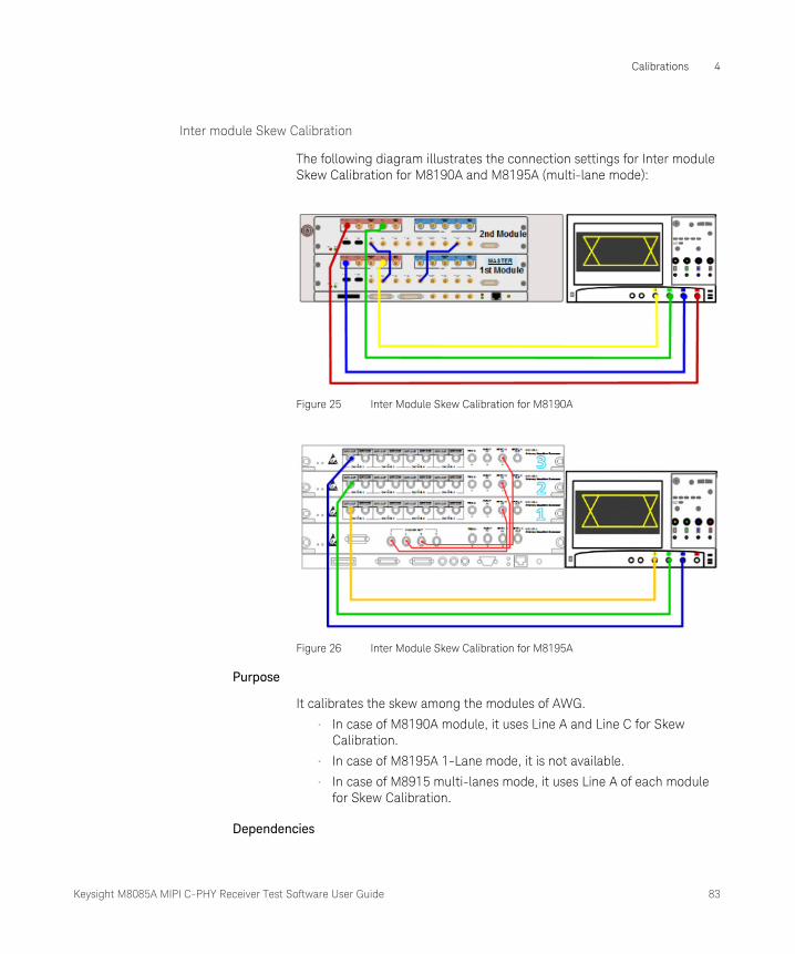
Keysight M8085A MIPI C-PHY Receiver Test Software User Guide 83
Calibrations 4
Inter module Skew Calibration
The following diagram illustrates the connection settings for Inter module Skew Calibration for M8190A and M8195A (multi-lane mode):
Figure 25 Inter Module Skew Calibration for M8190A
Figure 26 Inter Module Skew Calibration for M8195A
Purpose
It calibrates the skew among the modules of AWG.
• In case of M8190A module, it uses Line A and Line C for Skew Calibration.
• In case of M8195A 1-Lane mode, it is not available.
• In case of M8915 multi-lanes mode, it uses Line A of each module for Skew Calibration.
Dependencies
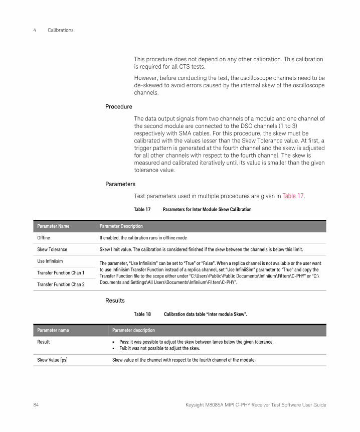
84 Keysight M8085A MIPI C-PHY Receiver Test Software User Guide
4 Calibrations
This procedure does not depend on any other calibration. This calibration is required for all CTS tests.
However, before conducting the test, the oscilloscope channels need to be de-skewed to avoid errors caused by the internal skew of the oscilloscope channels.
Procedure
The data output signals from two channels of a module and one channel of the second module are connected to the DSO channels (1 to 3) respectively with SMA cables. For this procedure, the skew must be calibrated with the values lesser than the Skew Tolerance value. At first, a trigger pattern is generated at the fourth channel and the skew is adjusted for all other channels with respect to the fourth channel. The skew is measured and calibrated iteratively until its value is smaller than the given tolerance value.
Parameters
Test parameters used in multiple procedures are given in Table 17.
Table 17 Parameters for Inter Module Skew Calibration
Results
Table 18 Calibration data table “Inter module Skew”.
Parameter Name Parameter Description
Offline If enabled, the calibration runs in offline mode
Skew Tolerance Skew limit value. The calibration is considered finished if the skew between the channels is below this limit.
Use Infiniisim The parameter, “Use Infiniisim” can be set to “True” or “False”. When a replica channel is not available or the user want to use Infiniisim Transfer Function instead of a replica channel, set “Use InfiniiSim” parameter to “True” and copy the Transfer Function file to the scope either under “C:\Users\Public\Public Documents\Infiniium\Filters\C-PHY” or “C:\Documents and Settings\All Users\Documents\Infiniium\Filters\C-PHY”.
Transfer Function Chan 1
Transfer Function Chan 2
Parameter name Parameter description
Result • Pass: it was possible to adjust the skew between lanes below the given tolerance.• Fail: it was not possible to adjust the skew.
Skew Value [ps] Skew value of the channel with respect to the fourth channel of the module.

Keysight M8085A MIPI C-PHY Receiver Test Software User Guide 85
Calibrations 4
LP Level Calibration High Data0 A (and B and C)
The following diagrams illustrate the connection settings for LP Level Calibration High Data 0 for the both AWGs, M8190A and M8195A respectively. This procedure applies to all modules.
Figure 27 LP Level Calibration High Data 0 A for M8190A
Figure 28 LP Level Calibration High Data 0 B for M8190A
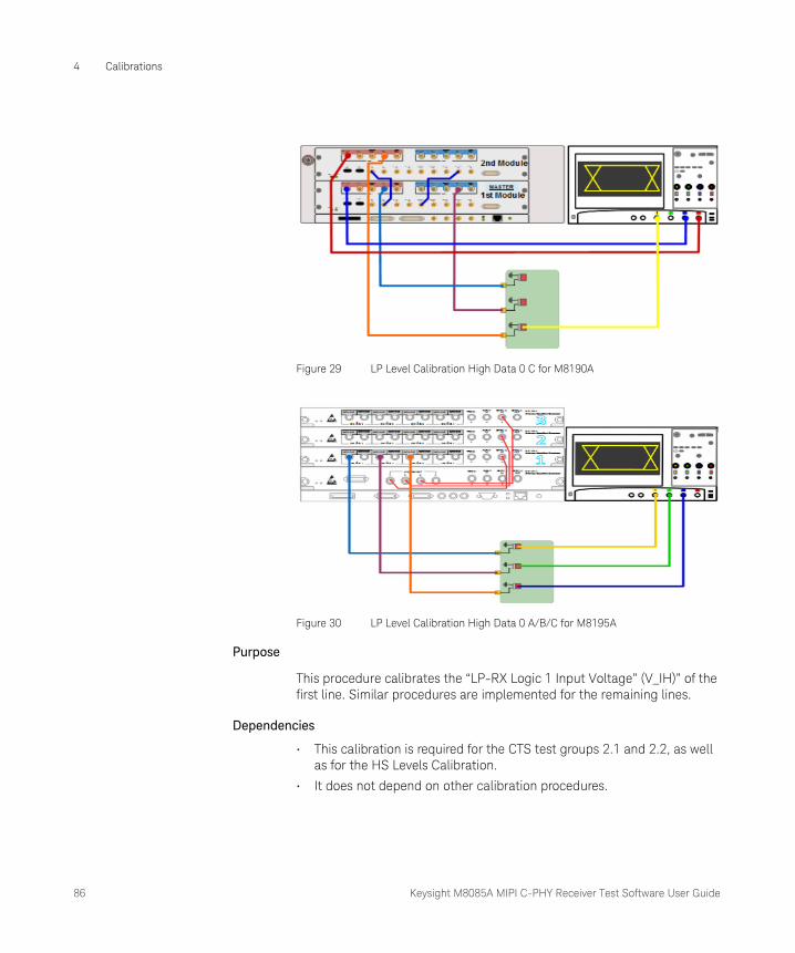
86 Keysight M8085A MIPI C-PHY Receiver Test Software User Guide
4 Calibrations
Figure 29 LP Level Calibration High Data 0 C for M8190A
Figure 30 LP Level Calibration High Data 0 A/B/C for M8195A
Purpose
This procedure calibrates the “LP-RX Logic 1 Input Voltage” (V_IH)” of the first line. Similar procedures are implemented for the remaining lines.
Dependencies
• This calibration is required for the CTS test groups 2.1 and 2.2, as well as for the HS Levels Calibration.
• It does not depend on other calibration procedures.

Keysight M8085A MIPI C-PHY Receiver Test Software User Guide 87
Calibrations 4
Procedure
The output signals are connected to the digital storage oscilloscope (for short, DSO or oscilloscope) channel 1 with a high impedance probe. An LP pattern is generated. Starting with the “Max Level” voltage, the LP high level is subsequently decremented by “Step Size” down to the “Min Level” voltage. The signal is measured with the DSO.
Parameters
Test parameters used in multiple procedures are given in Table 19.
Table 19 LP Level Calibration High Data 0
Results
Table 20 Calibration Data Table “LP Level Calibration Low (and Data0 to Data3)
Parameter Name Parameter Description
Calibration Pattern File Pattern file that is used for calibration procedures, which is different from the pattern definition used in the sequence files for configuring the DUT
Max LP High Level Maximum LP High Level voltage to calibrate
Min LP High Level Minimum LP High Level voltage to calibrate
Offline If enabled the calibration runs in offline mode
Step Size Step size to go from the maximum to minimum voltage during the calibration
Use Infiniisim The parameter, “Use Infiniisim” can be set to “True” or “False”. When a replica channel is not available or the user want to use Infiniisim Transfer Function instead of a replica channel, set “Use InfiniiSim” parameter to “True” and copy the Transfer Function file to the scope either under “C:\Users\Public\Public Documents\Infiniium\Filters\C-PHY” or “C:\Documents and Settings\All Users\Documents\Infiniium\Filters\C-PHY”.
Transfer Function Chan 1
Transfer Function Chan 2
Parameter Name Parameter Description
Result Pass: the measured level is within the expected range of +20% of the set levelFail: the measured level deviates more than 20% from the set level
Set Level [mV] Set value of the LP low level
Measured LP High Level [mV] Actual value as measured on channel 1 of the DSO using the most frequent value of a histogram measurement
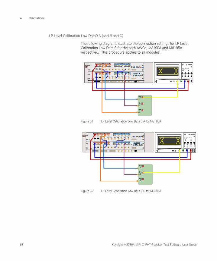
88 Keysight M8085A MIPI C-PHY Receiver Test Software User Guide
4 Calibrations
LP Level Calibration Low Data0 A (and B and C)
The following diagrams illustrate the connection settings for LP Level Calibration Low Data 0 for the both AWGs, M8190A and M8195A respectively. This procedure applies to all modules.
Figure 31 LP Level Calibration Low Data 0 A for M8190A
Figure 32 LP Level Calibration Low Data 0 B for M8190A

Keysight M8085A MIPI C-PHY Receiver Test Software User Guide 89
Calibrations 4
Figure 33 LP Level Calibration Low Data 0 C for M8190A
Figure 34 LP Level Calibration Low Data 0 A/B/C for M8195A
Purpose
This procedure calibrates the “LP-RX Logic 0 Input Voltage” (V_IL)” of the first line. Similar procedures are implemented for the remaining lines.
Dependencies
• This calibration is required for the CTS test groups 2.1 and 2.2, as well as for the HS Levels Calibration.
• It does not depend on other calibration procedures.
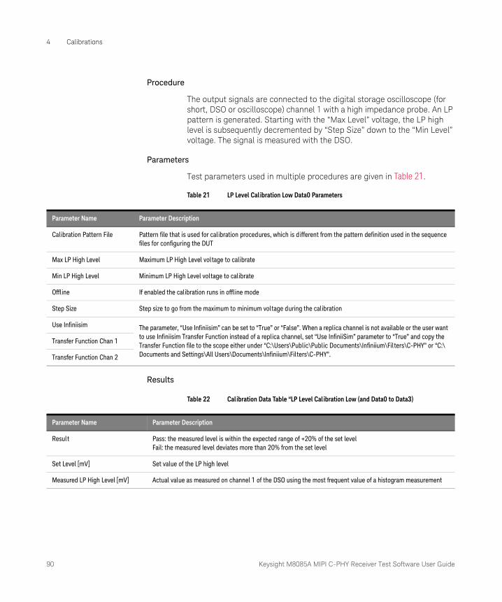
90 Keysight M8085A MIPI C-PHY Receiver Test Software User Guide
4 Calibrations
Procedure
The output signals are connected to the digital storage oscilloscope (for short, DSO or oscilloscope) channel 1 with a high impedance probe. An LP pattern is generated. Starting with the “Max Level” voltage, the LP high level is subsequently decremented by “Step Size” down to the “Min Level” voltage. The signal is measured with the DSO.
Parameters
Test parameters used in multiple procedures are given in Table 21.
Table 21 LP Level Calibration Low Data0 Parameters
Results
Table 22 Calibration Data Table “LP Level Calibration Low (and Data0 to Data3)
Parameter Name Parameter Description
Calibration Pattern File Pattern file that is used for calibration procedures, which is different from the pattern definition used in the sequence files for configuring the DUT
Max LP High Level Maximum LP High Level voltage to calibrate
Min LP High Level Minimum LP High Level voltage to calibrate
Offline If enabled the calibration runs in offline mode
Step Size Step size to go from the maximum to minimum voltage during the calibration
Use Infiniisim The parameter, “Use Infiniisim” can be set to “True” or “False”. When a replica channel is not available or the user want to use Infiniisim Transfer Function instead of a replica channel, set “Use InfiniiSim” parameter to “True” and copy the Transfer Function file to the scope either under “C:\Users\Public\Public Documents\Infiniium\Filters\C-PHY” or “C:\Documents and Settings\All Users\Documents\Infiniium\Filters\C-PHY”.
Transfer Function Chan 1
Transfer Function Chan 2
Parameter Name Parameter Description
Result Pass: the measured level is within the expected range of +20% of the set levelFail: the measured level deviates more than 20% from the set level
Set Level [mV] Set value of the LP high level
Measured LP High Level [mV] Actual value as measured on channel 1 of the DSO using the most frequent value of a histogram measurement
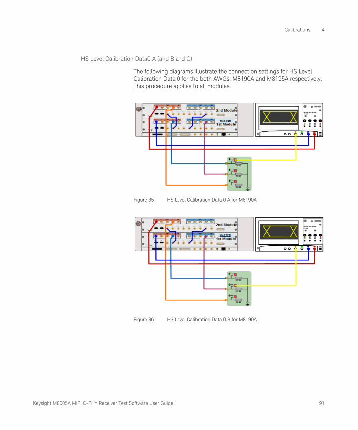
Keysight M8085A MIPI C-PHY Receiver Test Software User Guide 91
Calibrations 4
HS Level Calibration Data0 A (and B and C)
The following diagrams illustrate the connection settings for HS Level Calibration Data 0 for the both AWGs, M8190A and M8195A respectively. This procedure applies to all modules.
Figure 35 HS Level Calibration Data 0 A for M8190A
Figure 36 HS Level Calibration Data 0 B for M8190A
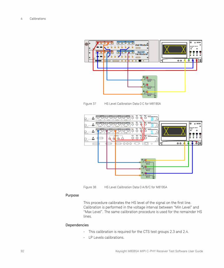
92 Keysight M8085A MIPI C-PHY Receiver Test Software User Guide
4 Calibrations
Figure 37 HS Level Calibration Data 0 C for M8190A
Figure 38 HS Level Calibration Data 0 A/B/C for M8195A
Purpose
This procedure calibrates the HS level of the signal on the first line. Calibration is performed in the voltage interval between “Min Level” and “Max Level”. The same calibration procedure is used for the remainder HS lines.
Dependencies
• This calibration is required for the CTS test groups 2.3 and 2.4.
• LP Levels calibrations.
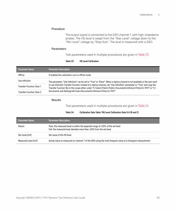
Keysight M8085A MIPI C-PHY Receiver Test Software User Guide 93
Calibrations 4
Procedure
The output signal is connected to the DSO channel 1 with high-impedance probes. The HS level is swept from the “Max Level” voltage down to the “Min Level” voltage by “Step Size”. The level is measured with a DSO.
Parameters
Test parameters used in multiple procedures are given in Table 23.
Table 23 HS Level Cal ibration
Results
Test parameters used in multiple procedures are given in Table 24.
Table 24 Calibration Data Table “HS Level Calibration Data 0 A (B and C)
Parameter Name Parameter Description
Offline If enabled the calibration runs in offline mode
Use Infiniisim The parameter, “Use Infiniisim” can be set to “True” or “False”. When a replica channel is not available or the user want to use Infiniisim Transfer Function instead of a replica channel, set “Use InfiniiSim” parameter to “True” and copy the Transfer Function file to the scope either under “C:\Users\Public\Public Documents\Infiniium\Filters\C-PHY” or “C:\Documents and Settings\All Users\Documents\Infiniium\Filters\C-PHY”.
Transfer Function Chan 1
Transfer Function Chan 2
Parameter Name Parameter Description
Result Pass: the measured level is within the expected range of ±20% of the set levelFail: the measured level deviates more than ±20% from the set level
Set Level [mV] Set value of the HS level
Measured Level [mV] Actual value as measured on channel 1 of the DSO using the most frequent value of a histogram measurement

94 Keysight M8085A MIPI C-PHY Receiver Test Software User Guide
4 Calibrations
e-Spike Calibration Data0 A
The following diagrams illustrate the connection settings for e-Spike Calibration Data 0 for the both AWGs, M8190A and M8195A respectively. This procedure applies to all modules.
Figure 39 e-Spike Calibration Data0 A for M8190A
Figure 40 e-Spike Calibration Data0 A for M8195A
Purpose
With e-Spikes the C-PHY input glitch rejection of the LP receivers is tested. The e-Spike calibration procedure calibrates the energy eSPIKE. Refer to the MIPI Alliance Conformance Test Suite for C-PHY v1.20 to know more about the concept of eSPIKE.

Keysight M8085A MIPI C-PHY Receiver Test Software User Guide 95
Calibrations 4
Dependencies
• The LP level calibrations must be performed before starting the e-Spike calibration.
• This calibration is only needed for test 2.1.5. Since it takes a very long time to complete, it can be skipped if test 2.1.5 is not going to be run.
Procedure
The e-Spike calibration is conducted on data lane Data0. The normal output signal is connected to the DSO channel 1 with high-impedance probes. A LP clock pattern containing spikes is generated.
The LP threshold level is then varied systematically between the selected limits. The e-Spike energy is the area of the e-Spike between V_IL and V_IH and measured with the oscilloscope.
Parameters
Test parameters used in multiple procedures are given in Table 25.
Table 25 eSpike Calibration
Parameter Name Parameter Description
Max Energy Value Maximum eSpike Energy to calibrate
Min Energy Value Minimum eSpike Energy to calibrate
Step Size Step size used to go from the minimum eSpike Energy to the maximum eSpike Energy
Logical 0 Threshold Logic 0 Input Voltage as defined in the C-PHY Editor
Logical 1 Threshold Logic 1 Input Voltage as defined in the C-PHY Editor
Max Threshold Difference Maximum of the difference V_IH – V_IL
Min Threshold Difference Minimum of the difference V_IH – V_IL
Min Level Minimum HS Level voltage to calibrate
Offline If enabled, the calibration runs in offline mode
Use Infiniisim The parameter, “Use Infiniisim” can be set to “True” or “False”. When a replica channel is not available or the user want to use Infiniisim Transfer Function instead of a replica channel, set “Use InfiniiSim” parameter to “True” and copy the Transfer Function file to the scope either under “C:\Users\Public\Public Documents\Infiniium\Filters\C-PHY” or “C:\Documents and Settings\All Users\Documents\Infiniium\Filters\C-PHY”.
Transfer Function Chan 1
Transfer Function Chan 2
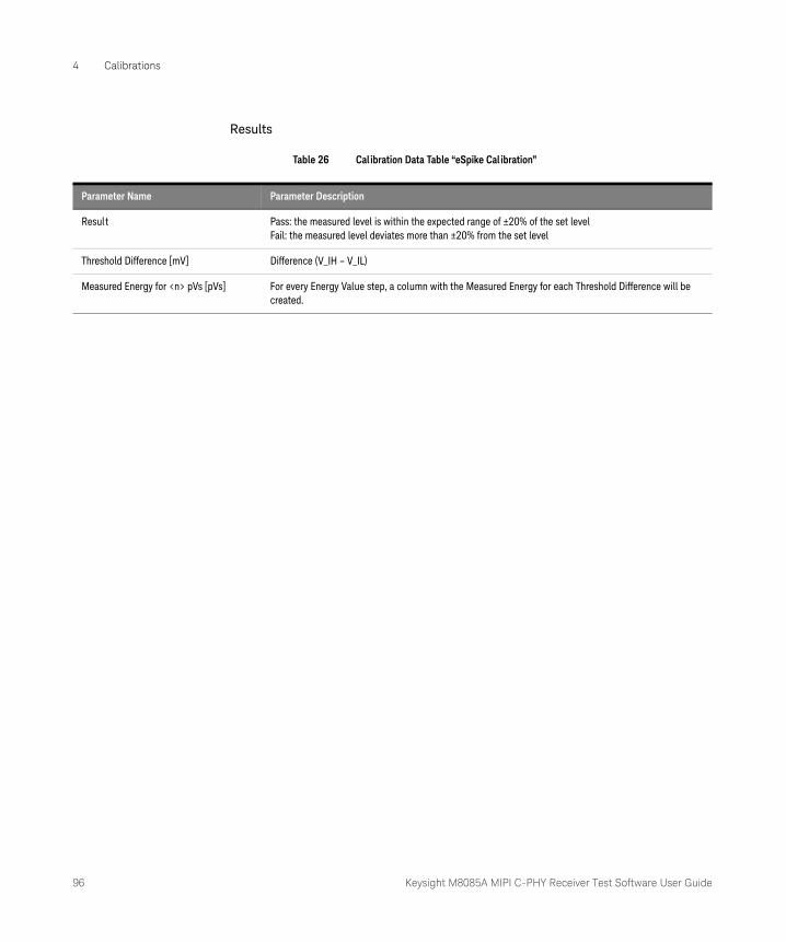
96 Keysight M8085A MIPI C-PHY Receiver Test Software User Guide
4 Calibrations
Results
Table 26 Calibration Data Table “eSpike Calibration”
Parameter Name Parameter Description
Result Pass: the measured level is within the expected range of ±20% of the set levelFail: the measured level deviates more than ±20% from the set level
Threshold Difference [mV] Difference (V_IH – V_IL)
Measured Energy for <n> pVs [pVs] For every Energy Value step, a column with the Measured Energy for each Threshold Difference will be created.
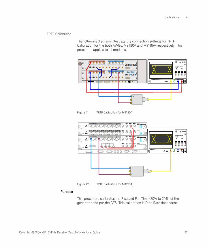
Keysight M8085A MIPI C-PHY Receiver Test Software User Guide 97
Calibrations 4
TRTF Calibration
The following diagrams illustrate the connection settings for TRTF Calibration for the both AWGs, M8190A and M8195A respectively. This procedure applies to all modules.
Figure 41 TRTF Calibration for M8190A
Figure 42 TRTF Calibration for M8195A
Purpose
This procedure calibrates the Rise and Fall Time (80% to 20%) of the generator and per the CTS. This calibration is Data Rate dependent.
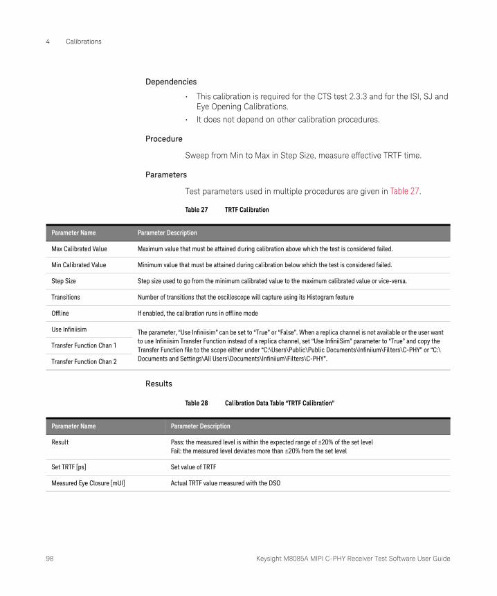
98 Keysight M8085A MIPI C-PHY Receiver Test Software User Guide
4 Calibrations
Dependencies
• This calibration is required for the CTS test 2.3.3 and for the ISI, SJ and Eye Opening Calibrations.
• It does not depend on other calibration procedures.
Procedure
Sweep from Min to Max in Step Size, measure effective TRTF time.
Parameters
Test parameters used in multiple procedures are given in Table 27.
Table 27 TRTF Calibration
Results
Table 28 Calibration Data Table “TRTF Calibration”
Parameter Name Parameter Description
Max Calibrated Value Maximum value that must be attained during calibration above which the test is considered failed.
Min Calibrated Value Minimum value that must be attained during calibration below which the test is considered failed.
Step Size Step size used to go from the minimum calibrated value to the maximum calibrated value or vice-versa.
Transitions Number of transitions that the oscilloscope will capture using its Histogram feature
Offline If enabled, the calibration runs in offline mode
Use Infiniisim The parameter, “Use Infiniisim” can be set to “True” or “False”. When a replica channel is not available or the user want to use Infiniisim Transfer Function instead of a replica channel, set “Use InfiniiSim” parameter to “True” and copy the Transfer Function file to the scope either under “C:\Users\Public\Public Documents\Infiniium\Filters\C-PHY” or “C:\Documents and Settings\All Users\Documents\Infiniium\Filters\C-PHY”.
Transfer Function Chan 1
Transfer Function Chan 2
Parameter Name Parameter Description
Result Pass: the measured level is within the expected range of ±20% of the set levelFail: the measured level deviates more than ±20% from the set level
Set TRTF [ps] Set value of TRTF
Measured Eye Closure [mUI] Actual TRTF value measured with the DSO
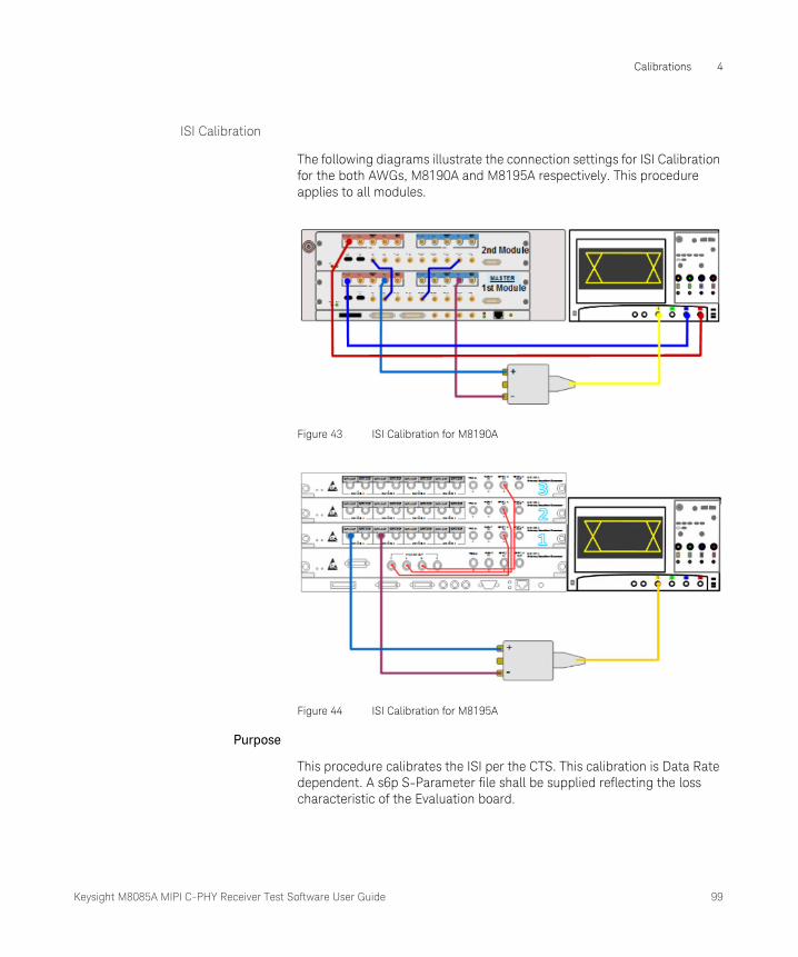
Keysight M8085A MIPI C-PHY Receiver Test Software User Guide 99
Calibrations 4
ISI Calibration
The following diagrams illustrate the connection settings for ISI Calibration for the both AWGs, M8190A and M8195A respectively. This procedure applies to all modules.
Figure 43 ISI Calibration for M8190A
Figure 44 ISI Calibration for M8195A
Purpose
This procedure calibrates the ISI per the CTS. This calibration is Data Rate dependent. A s6p S-Parameter file shall be supplied reflecting the loss characteristic of the Evaluation board.

100 Keysight M8085A MIPI C-PHY Receiver Test Software User Guide
4 Calibrations
Dependencies
• This calibration is required for the CTS test 2.3.3 and for the Eye Opening Calibration.
• It depends on the TRTF calibration.
Procedure
Measure ISI from s6p file.
Parameters
Test parameters used in multiple procedures are given in Table 29.
Table 29 ISI Calibration
Parameter Name Parameter Description
HS Sequence File Sequence file that is used for the calibration of the HS data instead of the sequence file specified while configuring the DUT.
Max Calibrated Value Maximum value that must be attained during calibration above which the test is considered failed.
Min Calibrated Value Minimum value that must be attained during calibration below which the test is considered failed.
Step Size Step size used to go from the minimum calibrated value to the maximum calibrated value
Six Port S-Parameter File The S-parameter file in the s6p format, which is used to emulate a channel during the test.
SParameter Type Number of ports (either Two Port or Six Port) selected for channel emulation.
Transitions Number of transitions that the oscilloscope will capture using its Histogram feature
Offline If enabled, the calibration runs in offline mode
Use Infiniisim The parameter, “Use Infiniisim” can be set to “True” or “False”. When a replica channel is not available or the user want to use Infiniisim Transfer Function instead of a replica channel, set “Use InfiniiSim” parameter to “True” and copy the Transfer Function file to the scope either under “C:\Users\Public\Public Documents\Infiniium\Filters\C-PHY” or “C:\Documents and Settings\All Users\Documents\Infiniium\Filters\C-PHY”.
Transfer Function Chan 1
Transfer Function Chan 2
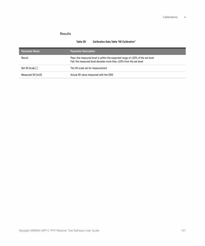
Keysight M8085A MIPI C-PHY Receiver Test Software User Guide 101
Calibrations 4
Results
Table 30 Calibration Data Table “ISI Calibration”
Parameter Name Parameter Description
Result Pass: the measured level is within the expected range of ±20% of the set levelFail: the measured level deviates more than ±20% from the set level
Set ISI Scale [ ] The ISI scale set for measurement
Measured ISI [mUI] Actual ISI value measured with the DSO

102 Keysight M8085A MIPI C-PHY Receiver Test Software User Guide
4 Calibrations
Sinusoidal Jitter Calibration (SJ Calibration)
The following diagrams illustrate the connection settings for SJ Calibration for the both AWGs, M8190A and M8195A respectively. This procedure applies to all modules.
Figure 45 SJ Calibration for M8190A
Figure 46 SJ Calibration for M8195A
Purpose
This procedure calibrates the Sinusoidal Jitter of the generator and per the CTS. This calibration is Data Rate dependent.
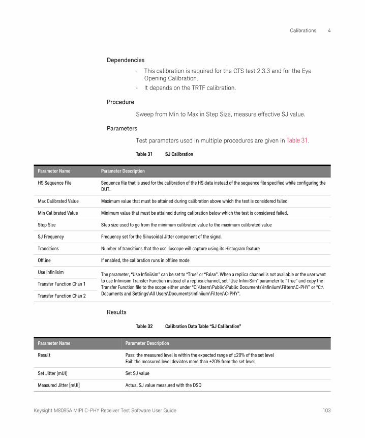
Keysight M8085A MIPI C-PHY Receiver Test Software User Guide 103
Calibrations 4
Dependencies
• This calibration is required for the CTS test 2.3.3 and for the Eye Opening Calibration.
• It depends on the TRTF calibration.
Procedure
Sweep from Min to Max in Step Size, measure effective SJ value.
Parameters
Test parameters used in multiple procedures are given in Table 31.
Table 31 SJ Cal ibration
Results
Table 32 Calibration Data Table “SJ Calibration”
Parameter Name Parameter Description
HS Sequence File Sequence file that is used for the calibration of the HS data instead of the sequence file specified while configuring the DUT.
Max Calibrated Value Maximum value that must be attained during calibration above which the test is considered failed.
Min Calibrated Value Minimum value that must be attained during calibration below which the test is considered failed.
Step Size Step size used to go from the minimum calibrated value to the maximum calibrated value
SJ Frequency Frequency set for the Sinusoidal Jitter component of the signal
Transitions Number of transitions that the oscilloscope will capture using its Histogram feature
Offline If enabled, the calibration runs in offline mode
Use Infiniisim The parameter, “Use Infiniisim” can be set to “True” or “False”. When a replica channel is not available or the user want to use Infiniisim Transfer Function instead of a replica channel, set “Use InfiniiSim” parameter to “True” and copy the Transfer Function file to the scope either under “C:\Users\Public\Public Documents\Infiniium\Filters\C-PHY” or “C:\Documents and Settings\All Users\Documents\Infiniium\Filters\C-PHY”.
Transfer Function Chan 1
Transfer Function Chan 2
Parameter Name Parameter Description
Result Pass: the measured level is within the expected range of ±20% of the set levelFail: the measured level deviates more than ±20% from the set level
Set Jitter [mUI] Set SJ value
Measured Jitter [mUI] Actual SJ value measured with the DSO
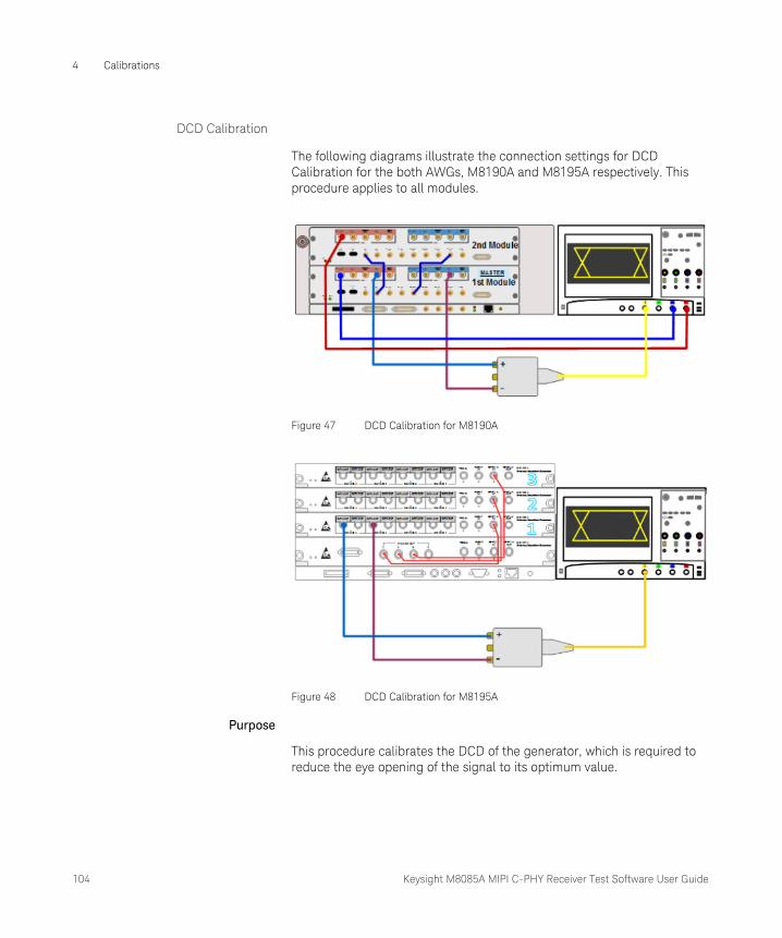
104 Keysight M8085A MIPI C-PHY Receiver Test Software User Guide
4 Calibrations
DCD Calibration
The following diagrams illustrate the connection settings for DCD Calibration for the both AWGs, M8190A and M8195A respectively. This procedure applies to all modules.
Figure 47 DCD Calibration for M8190A
Figure 48 DCD Calibration for M8195A
Purpose
This procedure calibrates the DCD of the generator, which is required to reduce the eye opening of the signal to its optimum value.

Keysight M8085A MIPI C-PHY Receiver Test Software User Guide 105
Calibrations 4
Dependencies
• This calibration is required for the CTS test 2.3.3 and for the Eye Opening Calibration.
Procedure
Sweep from Min Calibrated Value to Max Calibrated Value according to the Step Size, measure the effective jitter amplitude for the duty cycle.
Parameters
Test parameters used in multiple procedures are given in Table 33.
Table 33 DCD Calibration
Results
Table 34 Calibration Data Table “DCD Calibration”
Parameter Name Parameter Description
HS Sequence File Sequence file that is used for the calibration of the HS data instead of the sequence file specified while configuring the DUT.
Max Calibrated Value Maximum value that must be attained during calibration above which the test is considered failed.
Min Calibrated Value Minimum value that must be attained during calibration below which the test is considered failed.
Step Size Step size used to go from the minimum calibrated value to the maximum calibrated value
Transitions Number of transitions that the oscilloscope will capture using its Histogram feature
Offline If enabled, the calibration runs in offline mode
Use Infiniisim The parameter, “Use Infiniisim” can be set to “True” or “False”. When a replica channel is not available or the user want to use Infiniisim Transfer Function instead of a replica channel, set “Use InfiniiSim” parameter to “True” and copy the Transfer Function file to the scope either under “C:\Users\Public\Public Documents\Infiniium\Filters\C-PHY” or “C:\Documents and Settings\All Users\Documents\Infiniium\Filters\C-PHY”.
Transfer Function Chan 1
Transfer Function Chan 2
Parameter Name Parameter Description
Result Pass: the measured level is within the expected range of ±20% of the set levelFail: the measured level deviates more than ±20% from the set level
Set Jitter [mUI] Set jitter value for the signal edge times
Measured Jitter [mUI] Actual jitter value measured with the DSO

106 Keysight M8085A MIPI C-PHY Receiver Test Software User Guide
4 Calibrations
Eye Opening Calibration
The following diagrams illustrate the connection settings for DCD Calibration for the both AWGs, M8190A and M8195A respectively. This procedure applies to all modules.
Figure 49 DCD Calibration for M8190A
Figure 50 DCD Calibration for M8195A
Purpose
This procedure calibrates the Eye Opening per the CTS when all other impairments are present. This calibration is Data Rate dependent.
Dependencies
• This calibration is required for the CTS test 2.3.3.
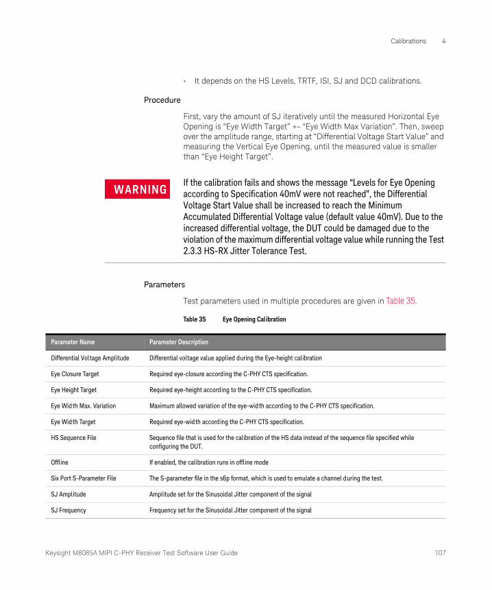
Keysight M8085A MIPI C-PHY Receiver Test Software User Guide 107
Calibrations 4
• It depends on the HS Levels, TRTF, ISI, SJ and DCD calibrations.
Procedure
First, vary the amount of SJ iteratively until the measured Horizontal Eye Opening is “Eye Width Target” +- “Eye Width Max Variation”. Then, sweep over the amplitude range, starting at “Differential Voltage Start Value” and measuring the Vertical Eye Opening, until the measured value is smaller than “Eye Height Target”.
Parameters
Test parameters used in multiple procedures are given in Table 35.
Table 35 Eye Opening Calibration
WARNINGIf the calibration fails and shows the message “Levels for Eye Opening according to Specification 40mV were not reached”, the Differential Voltage Start Value shall be increased to reach the Minimum Accumulated Differential Voltage value (default value 40mV). Due to the increased differential voltage, the DUT could be damaged due to the violation of the maximum differential voltage value while running the Test 2.3.3 HS-RX Jitter Tolerance Test.
Parameter Name Parameter Description
Differential Voltage Amplitude Differential voltage value applied during the Eye-height calibration
Eye Closure Target Required eye-closure according the C-PHY CTS specification.
Eye Height Target Required eye-height according to the C-PHY CTS specification.
Eye Width Max. Variation Maximum allowed variation of the eye-width according to the C-PHY CTS specification.
Eye Width Target Required eye-width according the C-PHY CTS specification.
HS Sequence File Sequence file that is used for the calibration of the HS data instead of the sequence file specified while configuring the DUT.
Offline If enabled, the calibration runs in offline mode
Six Port S-Parameter File The S-parameter file in the s6p format, which is used to emulate a channel during the test.
SJ Amplitude Amplitude set for the Sinusoidal Jitter component of the signal
SJ Frequency Frequency set for the Sinusoidal Jitter component of the signal
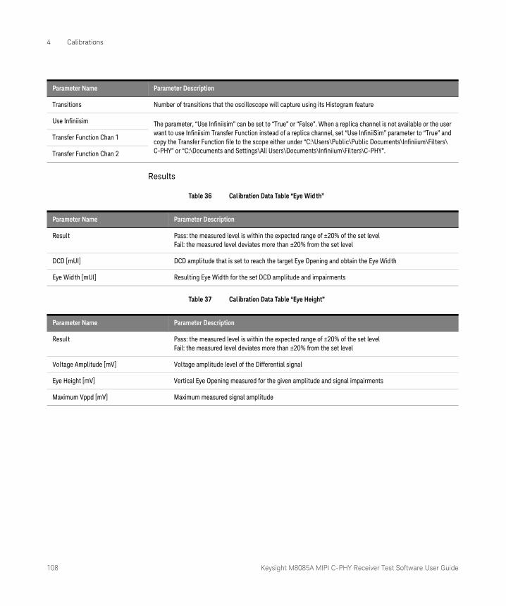
108 Keysight M8085A MIPI C-PHY Receiver Test Software User Guide
4 Calibrations
Results
Table 36 Calibration Data Table “Eye Wid th”
Table 37 Calibration Data Table “Eye Height”
Transitions Number of transitions that the oscilloscope will capture using its Histogram feature
Use Infiniisim The parameter, “Use Infiniisim” can be set to “True” or “False”. When a replica channel is not available or the user want to use Infiniisim Transfer Function instead of a replica channel, set “Use InfiniiSim” parameter to “True” and copy the Transfer Function file to the scope either under “C:\Users\Public\Public Documents\Infiniium\Filters\C-PHY” or “C:\Documents and Settings\All Users\Documents\Infiniium\Filters\C-PHY”.
Transfer Function Chan 1
Transfer Function Chan 2
Parameter Name Parameter Description
Parameter Name Parameter Description
Result Pass: the measured level is within the expected range of ±20% of the set levelFail: the measured level deviates more than ±20% from the set level
DCD [mUI] DCD amplitude that is set to reach the target Eye Opening and obtain the Eye Width
Eye Width [mUI] Resulting Eye Width for the set DCD amplitude and impairments
Parameter Name Parameter Description
Result Pass: the measured level is within the expected range of ±20% of the set levelFail: the measured level deviates more than ±20% from the set level
Voltage Amplitude [mV] Voltage amplitude level of the Differential signal
Eye Height [mV] Vertical Eye Opening measured for the given amplitude and signal impairments
Maximum Vppd [mV] Maximum measured signal amplitude
Keysight M8085A MIPI C-PHY Receiver Test Software
User Guide
5 Test Procedures
Connection Diagrams for the Test Procedures / 110
HS Tests / 112
Semi-Automated Tests / 126
LP Tests / 130
Behavioral Tests / 146
The MIPI C-PHY receiver tests comprise of the following test groups:
• HS Tests
• Semi-Automated Tests
• LP Tests
• Behavioral Tests
This grouping streamlines the test process by minimizing the number of physical reconnection of cables and other test accessories.
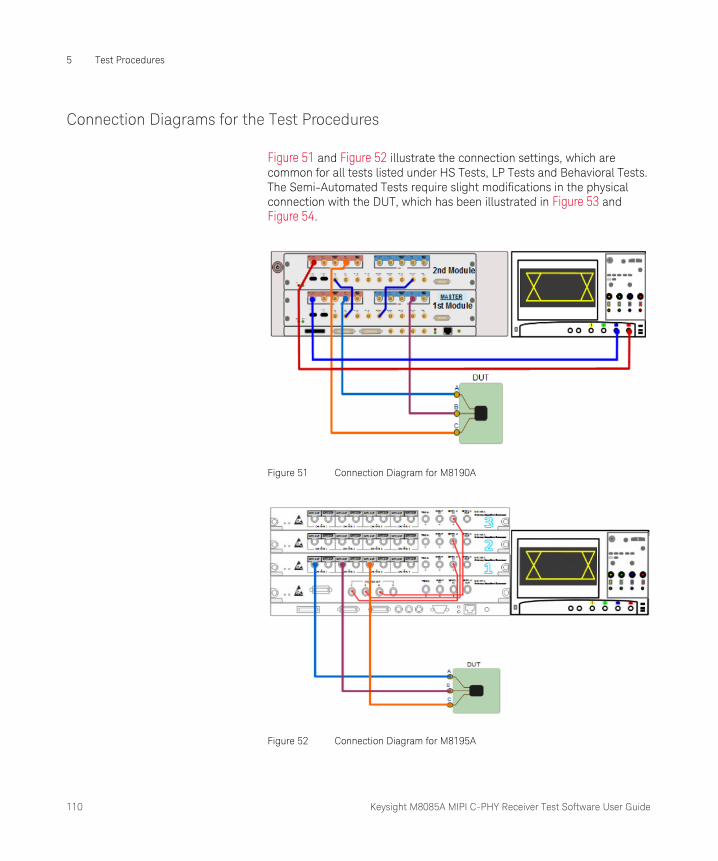
110 Keysight M8085A MIPI C-PHY Receiver Test Software User Guide
5 Test Procedures
Connection Diagrams for the Test Procedures
Figure 51 and Figure 52 illustrate the connection settings, which are common for all tests listed under HS Tests, LP Tests and Behavioral Tests. The Semi-Automated Tests require slight modifications in the physical connection with the DUT, which has been illustrated in Figure 53 and Figure 54.
Figure 51 Connection Diagram for M8190A
Figure 52 Connection Diagram for M8195A
Keysight M8085A MIPI C-PHY Receiver Test Software User Guide 111
Test Procedures 5
Each test can be performed in two modes: Compliance Mode and Expert Mode. (Refer to Accessing the MIPI C-PHY CTS Plug-in on page 15). While the Compliance Mode has pre-defined optimal values for the test parameters that cannot be modified; the Expert Mode allows you to customize values or limits for the parameters, only if required, so that you may analyze the behavior and limitations of a test. By default, the field for each parameter displays the values/limits from the CTS. If needed, edit the parameter values/limits to those supported by your DUT, which may be less than or beyond the CTS limits.
In Compliance Mode and in the Expert Mode, follow the steps given below, which are common to all test procedures under the test groups—Clock, Data, Semi-Automated Tests and LP Tests:
• Make the connections for the selected test procedure as per the connection diagram shown in Figure 51 and Figure 52 (Figure 53 and Figure 54 for Semi-Automated tests) for M8190A and M8195A respectively.
• Click Run to transmit the test sequence to the DUT. Refer to Running Tests on page 26 to know how to run procedures.
• From the Results Table, verify that the DUT received the test sequence without errors.
For the remaining test groups, some of the tests additionally require some manual steps to be performed, which have been described in the respective sections.
NOTEThe test procedures described below are performed using the M8190A and M8195A AWG models. For the M8195A AWG model, the “Number of Lanes:” is selected as ‘1 Lane’. If you select the “Number of Lanes:” as ‘2 Lanes’ or ‘3 Lanes’, the C-PHY CTS plug-in also displays the tests for Data1 and Data2 lanes, respectively. For a certain test name corresponding to Data1 or Data2 Lane, use the same test procedures described for Data0 lane.
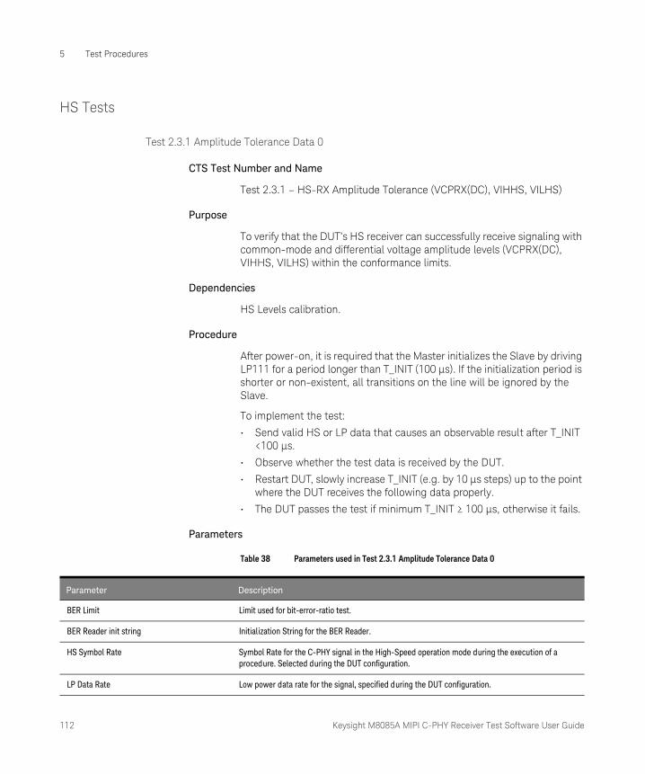
112 Keysight M8085A MIPI C-PHY Receiver Test Software User Guide
5 Test Procedures
HS Tests
Test 2.3.1 Amplitude Tolerance Data 0
CTS Test Number and Name
Test 2.3.1 – HS-RX Amplitude Tolerance (VCPRX(DC), VIHHS, VILHS)
Purpose
To verify that the DUT’s HS receiver can successfully receive signaling with common-mode and differential voltage amplitude levels (VCPRX(DC), VIHHS, VILHS) within the conformance limits.
Dependencies
HS Levels calibration.
Procedure
After power-on, it is required that the Master initializes the Slave by driving LP111 for a period longer than T_INIT (100 µs). If the initialization period is shorter or non-existent, all transitions on the line will be ignored by the Slave.
To implement the test:
• Send valid HS or LP data that causes an observable result after T_INIT <100 µs.
• Observe whether the test data is received by the DUT.
• Restart DUT, slowly increase T_INIT (e.g. by 10 µs steps) up to the point where the DUT receives the following data properly.
• The DUT passes the test if minimum T_INIT ≥ 100 µs, otherwise it fails.
Parameters
Table 38 Parameters used in Test 2.3.1 Amplitude Tolerance Data 0
Parameter Description
BER Limit Limit used for bit-error-ratio test.
BER Reader init string Initialization String for the BER Reader.
HS Symbol Rate Symbol Rate for the C-PHY signal in the High-Speed operation mode during the execution of a procedure. Selected during the DUT configuration.
LP Data Rate Low power data rate for the signal, specified during the DUT configuration.
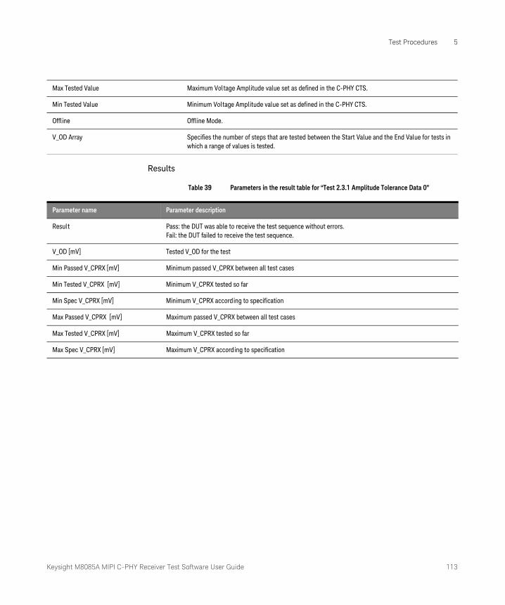
Keysight M8085A MIPI C-PHY Receiver Test Software User Guide 113
Test Procedures 5
Results
Table 39 Parameters in the result table for “Test 2.3.1 Amplitude Tolerance Data 0”
Max Tested Value Maximum Voltage Amplitude value set as defined in the C-PHY CTS.
Min Tested Value Minimum Voltage Amplitude value set as defined in the C-PHY CTS.
Offline Offline Mode.
V_OD Array Specifies the number of steps that are tested between the Start Value and the End Value for tests in which a range of values is tested.
Parameter name Parameter description
Result Pass: the DUT was able to receive the test sequence without errors.Fail: the DUT failed to receive the test sequence.
V_OD [mV] Tested V_OD for the test
Min Passed V_CPRX [mV] Minimum passed V_CPRX between all test cases
Min Tested V_CPRX [mV] Minimum V_CPRX tested so far
Min Spec V_CPRX [mV] Minimum V_CPRX according to specification
Max Passed V_CPRX [mV] Maximum passed V_CPRX between all test cases
Max Tested V_CPRX [mV] Maximum V_CPRX tested so far
Max Spec V_CPRX [mV] Maximum V_CPRX according to specification

114 Keysight M8085A MIPI C-PHY Receiver Test Software User Guide
5 Test Procedures
Test 2.3.2 V_IDTH and V_IDTL Sensitivity Data 0
CTS Test Number and Name
Test 2.3.2 – HS-RX Differential Input High/Low Thresholds (VIDTH, VIDTL)
Purpose
To verify that the DUT’s HS receiver can properly detect VOD voltage levels that are at least as small as the minimum required values (VIDTH, VIDTL).
Dependencies
HS Levels calibration.
Procedure
Starting with nominal levels, reduce the differential amplitude until the DUT fails. Record the last working value.
Parameters
Table 40 Parameters used in Test 2.3.2 V_IDTH and V_IDTL Sensitivity Data 0
Parameter Description
BER Limit Limit used for bit-error-ratio test.
BER Reader init string Initialization String for the BER Reader.
HS Symbol Rate Symbol Rate for the C-PHY signal in the High-Speed operation mode during the execution of a procedure. Selected during the DUT configuration.
LP Data Rate Low power data rate for the signal, specified during the DUT configuration.
Minimum Tested Vppd Minimum Peak-to-Peak Differential Voltage as defined in the C-PHY CTS.
Offline Offline Mode.
Steps Step size used to go from the minimum calibrated value to the maximum calibrated value.
V_IHHS Set value of Single-ended Input High Voltage
V_ILHS Set value of Single-ended Input Low Voltage
V_MID Set value of Single-ended Input Middle Voltage

Keysight M8085A MIPI C-PHY Receiver Test Software User Guide 115
Test Procedures 5
Results
For all test cases, the DUT must successfully receive the HS burst data without error.
Table 41 Parameters in the result table for “Test 2.3.2 V_IDTH and V_IDTL Sensitivity Data 0”
Parameter name Parameter description
Result Pass: the DUT's V_IDTH and V_IDTL minimum values conform to the specificationFail: the DUT was not able to receive the test sequence with V_IDTH and V_IDTL values within the specification
V_CM [mV] Common-mode level used during the test
Min Passed V_IDTH/V_IDTL [mV] Minimum value of V_IDTH and V_IDTL for which the DUT passed the test
Min Tested V_IDTH/V_IDTL [mV] Minimum value tested for V_IDTH and V_IDTL
Min Spec [mV] Minimum value of V_IDTH and V_IDTL according to the specification

116 Keysight M8085A MIPI C-PHY Receiver Test Software User Guide
5 Test Procedures
Test 2.3.3 Jitter Tolerance Data 0
CTS Test Number and Name
Test 2.3.3 – HS-RX Jitter Tolerance
Purpose
To verify that the DUT can tolerate signaling with worst-case timing error.
Dependencies
HS levels calibrations and all Jitter calibrations (TRTF, ISI, SJ, Eye Opening)
Procedure
The eye is closed according to the CTS and HS data transmission is performed at 175mV and 310mV common mode levels. The DUT will receive the data successfully to pass the test.
Parameters
Table 42 Parameters used in Test 2.3.3 Jitter Tolerance Data 0
WARNINGDuring the Eye Opening Calibration, if the Differential Voltage Start Value is increased to achieve the Minimum Accumulated Differential Voltage (that is, 40mV), the Differential Amplitude set during this test to achieve the required eye opening may exceed the specification limits, which in turn, may damage the DUT.
Parameter Description
BER Limit Limit used for bit-error-ratio test.
BER Reader init string Initialization String for the BER Reader.
Eye Closure Target Required eye-closure according the C-PHY CTS specification.
Eye Height Target Required eye-height according to the C-PHY CTS specification.
Eye Width Target Required eye-width according the C-PHY CTS specification.
HS Symbol Rate Symbol Rate for the C-PHY signal in the High-Speed operation mode during the execution of a procedure. Selected during the DUT configuration.
ISI InterSymbol Interference value set for the C-PHY signal.
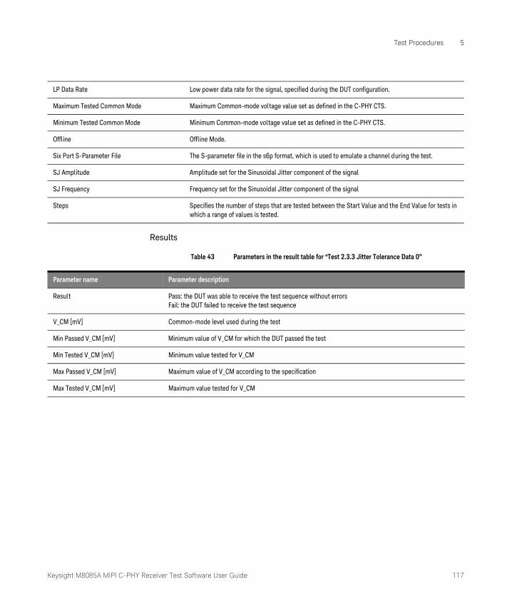
Keysight M8085A MIPI C-PHY Receiver Test Software User Guide 117
Test Procedures 5
Results
Table 43 Parameters in the result table for “Test 2.3.3 Jitter Tolerance Data 0”
LP Data Rate Low power data rate for the signal, specified during the DUT configuration.
Maximum Tested Common Mode Maximum Common-mode voltage value set as defined in the C-PHY CTS.
Minimum Tested Common Mode Minimum Common-mode voltage value set as defined in the C-PHY CTS.
Offline Offline Mode.
Six Port S-Parameter File The S-parameter file in the s6p format, which is used to emulate a channel during the test.
SJ Amplitude Amplitude set for the Sinusoidal Jitter component of the signal
SJ Frequency Frequency set for the Sinusoidal Jitter component of the signal
Steps Specifies the number of steps that are tested between the Start Value and the End Value for tests inwhich a range of values is tested.
Parameter name Parameter description
Result Pass: the DUT was able to receive the test sequence without errors Fail: the DUT failed to receive the test sequence
V_CM [mV] Common-mode level used during the test
Min Passed V_CM [mV] Minimum value of V_CM for which the DUT passed the test
Min Tested V_CM [mV] Minimum value tested for V_CM
Max Passed V_CM [mV] Maximum value of V_CM according to the specification
Max Tested V_CM [mV] Maximum value tested for V_CM

118 Keysight M8085A MIPI C-PHY Receiver Test Software User Guide
5 Test Procedures
Test 2.4.2 T_HS-Prepare - Data0 Procedure
CTS Test Number and Name
Test 2.4.2 – HS-RX T3-PREPARE Tolerance
Purpose
To verify that the DUT’s HS-RX can tolerate reception of values that conform for T3-PREPARE.
Dependencies
HS Levels calibration.
Procedure
Test the two cases in the CTS (38ns and 95ns prepare time) while all the other timings are also as stated in the CTS:
• Tlpx: 50ns
• T3-POST Time Interval: 224 UI
• T3-PREBEGIN Time Interval: 448 UI
• T3-PREEND Time Interval: 7 UI
• T3-PROGSEQ: Disabled
• T3-SYNC: 3444443 (7 UI)
Parameters
Table 44 Parameters used in Test 2.4.2 T_HS-Prepare - Data0 Procedure
Parameter Description
BER Limit Limit used for bit-error-ratio test.
BER Reader init string Initialization String for the BER Reader.
End Value End value of the Prepare time on the HS signal.
HS Symbol Rate Symbol Rate for the C-PHY signal in the High-Speed operation mode during the execution of a procedure. Selected during the DUT configuration.
LP Data Rate Low power data rate for the signal, specified during the DUT configuration.
Offline Offline Mode.
Start Value Start value of the Prepare time on the HS signal.
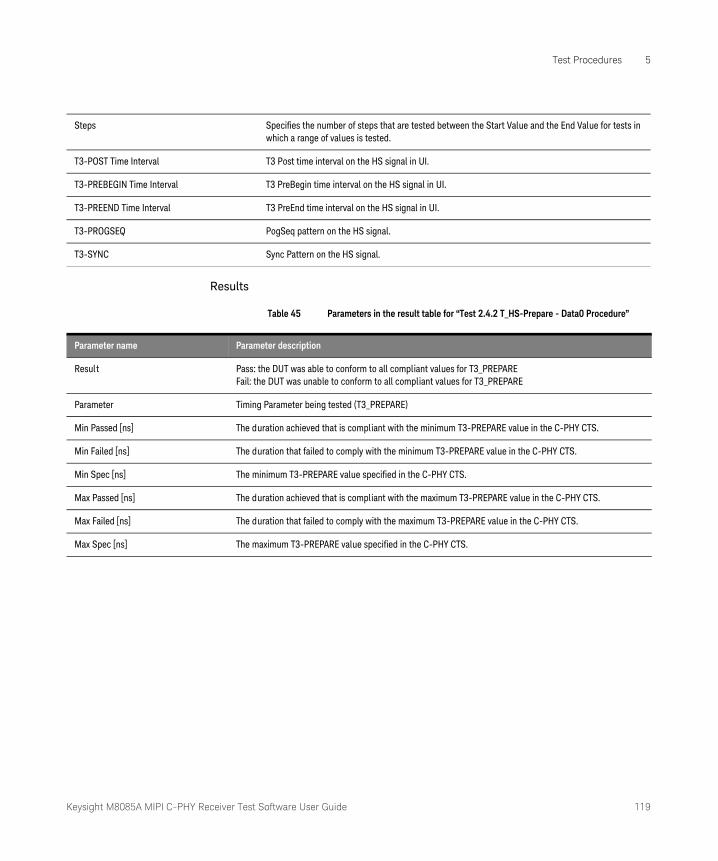
Keysight M8085A MIPI C-PHY Receiver Test Software User Guide 119
Test Procedures 5
Results
Table 45 Parameters in the result table for “Test 2.4.2 T_HS-Prepare - Data0 Procedure”
Steps Specifies the number of steps that are tested between the Start Value and the End Value for tests inwhich a range of values is tested.
T3-POST Time Interval T3 Post time interval on the HS signal in UI.
T3-PREBEGIN Time Interval T3 PreBegin time interval on the HS signal in UI.
T3-PREEND Time Interval T3 PreEnd time interval on the HS signal in UI.
T3-PROGSEQ PogSeq pattern on the HS signal.
T3-SYNC Sync Pattern on the HS signal.
Parameter name Parameter description
Result Pass: the DUT was able to conform to all compliant values for T3_PREPAREFail: the DUT was unable to conform to all compliant values for T3_PREPARE
Parameter Timing Parameter being tested (T3_PREPARE)
Min Passed [ns] The duration achieved that is compliant with the minimum T3-PREPARE value in the C-PHY CTS.
Min Failed [ns] The duration that failed to comply with the minimum T3-PREPARE value in the C-PHY CTS.
Min Spec [ns] The minimum T3-PREPARE value specified in the C-PHY CTS.
Max Passed [ns] The duration achieved that is compliant with the maximum T3-PREPARE value in the C-PHY CTS.
Max Failed [ns] The duration that failed to comply with the maximum T3-PREPARE value in the C-PHY CTS.
Max Spec [ns] The maximum T3-PREPARE value specified in the C-PHY CTS.
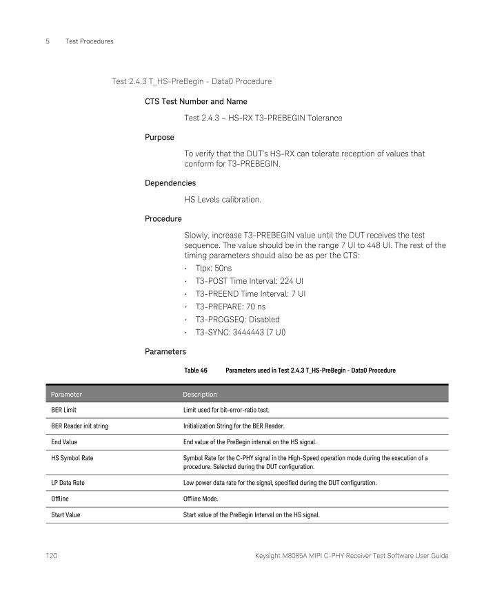
120 Keysight M8085A MIPI C-PHY Receiver Test Software User Guide
5 Test Procedures
Test 2.4.3 T_HS-PreBegin - Data0 Procedure
CTS Test Number and Name
Test 2.4.3 – HS-RX T3-PREBEGIN Tolerance
Purpose
To verify that the DUT’s HS-RX can tolerate reception of values that conform for T3-PREBEGIN.
Dependencies
HS Levels calibration.
Procedure
Slowly, increase T3-PREBEGIN value until the DUT receives the test sequence. The value should be in the range 7 UI to 448 UI. The rest of the timing parameters should also be as per the CTS:
• Tlpx: 50ns
• T3-POST Time Interval: 224 UI
• T3-PREEND Time Interval: 7 UI
• T3-PREPARE: 70 ns
• T3-PROGSEQ: Disabled
• T3-SYNC: 3444443 (7 UI)
Parameters
Table 46 Parameters used in Test 2.4.3 T_HS-PreBegin - Data0 Procedure
Parameter Description
BER Limit Limit used for bit-error-ratio test.
BER Reader init string Initialization String for the BER Reader.
End Value End value of the PreBegin interval on the HS signal.
HS Symbol Rate Symbol Rate for the C-PHY signal in the High-Speed operation mode during the execution of a procedure. Selected during the DUT configuration.
LP Data Rate Low power data rate for the signal, specified during the DUT configuration.
Offline Offline Mode.
Start Value Start value of the PreBegin Interval on the HS signal.
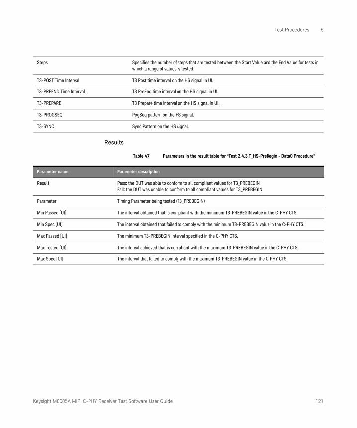
Keysight M8085A MIPI C-PHY Receiver Test Software User Guide 121
Test Procedures 5
Results
Table 47 Parameters in the result table for “Test 2.4.3 T_HS-PreBegin - Data0 Procedure”
Steps Specifies the number of steps that are tested between the Start Value and the End Value for tests inwhich a range of values is tested.
T3-POST Time Interval T3 Post time interval on the HS signal in UI.
T3-PREEND Time Interval T3 PreEnd time interval on the HS signal in UI.
T3-PREPARE T3 Prepare time interval on the HS signal in UI.
T3-PROGSEQ PogSeq pattern on the HS signal.
T3-SYNC Sync Pattern on the HS signal.
Parameter name Parameter description
Result Pass: the DUT was able to conform to all compliant values for T3_PREBEGINFail: the DUT was unable to conform to all compliant values for T3_PREBEGIN
Parameter Timing Parameter being tested (T3_PREBEGIN)
Min Passed [UI] The interval obtained that is compliant with the minimum T3-PREBEGIN value in the C-PHY CTS.
Min Spec [UI] The interval obtained that failed to comply with the minimum T3-PREBEGIN value in the C-PHY CTS.
Max Passed [UI] The minimum T3-PREBEGIN interval specified in the C-PHY CTS.
Max Tested [UI] The interval achieved that is compliant with the maximum T3-PREBEGIN value in the C-PHY CTS.
Max Spec [UI] The interval that failed to comply with the maximum T3-PREBEGIN value in the C-PHY CTS.
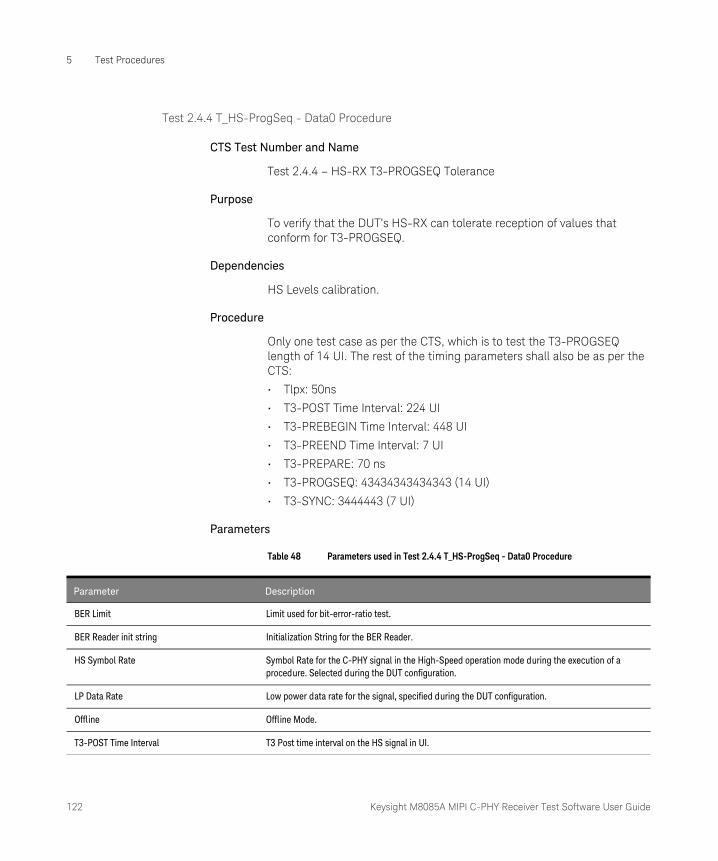
122 Keysight M8085A MIPI C-PHY Receiver Test Software User Guide
5 Test Procedures
Test 2.4.4 T_HS-ProgSeq - Data0 Procedure
CTS Test Number and Name
Test 2.4.4 – HS-RX T3-PROGSEQ Tolerance
Purpose
To verify that the DUT’s HS-RX can tolerate reception of values that conform for T3-PROGSEQ.
Dependencies
HS Levels calibration.
Procedure
Only one test case as per the CTS, which is to test the T3-PROGSEQ length of 14 UI. The rest of the timing parameters shall also be as per the CTS:
• Tlpx: 50ns
• T3-POST Time Interval: 224 UI
• T3-PREBEGIN Time Interval: 448 UI
• T3-PREEND Time Interval: 7 UI
• T3-PREPARE: 70 ns
• T3-PROGSEQ: 43434343434343 (14 UI)
• T3-SYNC: 3444443 (7 UI)
Parameters
Table 48 Parameters used in Test 2.4.4 T_HS-ProgSeq - Data0 Procedure
Parameter Description
BER Limit Limit used for bit-error-ratio test.
BER Reader init string Initialization String for the BER Reader.
HS Symbol Rate Symbol Rate for the C-PHY signal in the High-Speed operation mode during the execution of a procedure. Selected during the DUT configuration.
LP Data Rate Low power data rate for the signal, specified during the DUT configuration.
Offline Offline Mode.
T3-POST Time Interval T3 Post time interval on the HS signal in UI.

Keysight M8085A MIPI C-PHY Receiver Test Software User Guide 123
Test Procedures 5
Results
Table 49 Parameters in the result table for “Test 2.4.4 T_HS-ProgSeq - Data0 Procedure”
T3-PREBEGIN Time Interval T3 PreEnd time interval on the HS signal in UI.
T3-PREEND Time Interval T3 PreBegin time interval on the HS signal in UI.
T3-PREPARE T3 Prepare time interval on the HS signal in UI.
T3-PROGSEQ PogSeq pattern on the HS signal.
T3-SYNC Sync Pattern on the HS signal.
Parameter name Parameter description
Result Pass: the DUT was able to conform to all compliant values for T3_PROGSEQFail: the DUT was unable to conform to all compliant values for T3_PROGSEQ
Parameter Timing Parameter being tested (T3_PROGSEQ)
Min Passed [UI] The interval obtained that is compliant with the minimum T3-PROGSEQ value in the C-PHY CTS.
Min Spec [UI] The minimum T3-PROGSEQ interval specified in the C-PHY CTS.
Max Passed [UI] The interval obtained that is compliant with the maximum T3-PROGSEQ value in the C-PHY CTS.
Max Spec [UI] The maximum T3-PROGSEQ interval specified in the C-PHY CTS.

124 Keysight M8085A MIPI C-PHY Receiver Test Software User Guide
5 Test Procedures
Test 2.4.5 T_HS-Post - Data0 Procedure
CTS Test Number and Name
Test 2.4.5 – HS-RX T3-POST Tolerance
Purpose
To verify that the DUT’s HS-RX can tolerate reception of values that conform for T3-POST.
Dependencies
HS Levels calibration.
Procedure
Only one test case as per the CTS, which is T3-POST detection threshold, is between 7UI and 224UI. The rest of the timing parameters shall also be as per the CTS:
• Tlpx: 50ns
• T3-PREBEGIN Time Interval: 448 UI
• T3-PREEND Time Interval: 7 UI
• T3-PREPARE: 70 ns
• T3-PROGSEQ: Disabled
• T3-SYNC: 3444443 (7 UI)
Parameters
Table 50 Parameters used in Test 2.4.5 T_HS-Post - Data0 Procedure
Parameter Description
BER Limit Limit used for bit-error-ratio test.
BER Reader init string Initialization String for the BER Reader.
End Value End value of the Post interval on the HS signal.
HS Symbol Rate Symbol Rate for the C-PHY signal in the High-Speed operation mode during the execution of a procedure. Selected during the DUT configuration.
LP Data Rate Low power data rate for the signal, specified during the DUT configuration.
Offline Offline Mode.
Start Value Start value of the Post Interval on the HS signal.
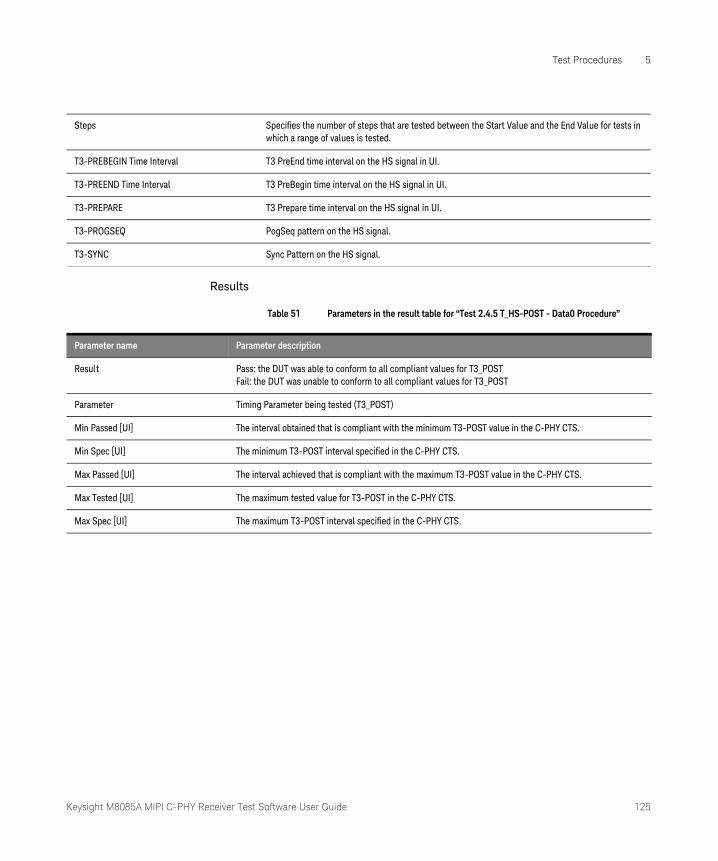
Keysight M8085A MIPI C-PHY Receiver Test Software User Guide 125
Test Procedures 5
Results
Table 51 Parameters in the result table for “Test 2.4.5 T_HS-POST - Data0 Procedure”
Steps Specifies the number of steps that are tested between the Start Value and the End Value for tests inwhich a range of values is tested.
T3-PREBEGIN Time Interval T3 PreEnd time interval on the HS signal in UI.
T3-PREEND Time Interval T3 PreBegin time interval on the HS signal in UI.
T3-PREPARE T3 Prepare time interval on the HS signal in UI.
T3-PROGSEQ PogSeq pattern on the HS signal.
T3-SYNC Sync Pattern on the HS signal.
Parameter name Parameter description
Result Pass: the DUT was able to conform to all compliant values for T3_POSTFail: the DUT was unable to conform to all compliant values for T3_POST
Parameter Timing Parameter being tested (T3_POST)
Min Passed [UI] The interval obtained that is compliant with the minimum T3-POST value in the C-PHY CTS.
Min Spec [UI] The minimum T3-POST interval specified in the C-PHY CTS.
Max Passed [UI] The interval achieved that is compliant with the maximum T3-POST value in the C-PHY CTS.
Max Tested [UI] The maximum tested value for T3-POST in the C-PHY CTS.
Max Spec [UI] The maximum T3-POST interval specified in the C-PHY CTS.

126 Keysight M8085A MIPI C-PHY Receiver Test Software User Guide
5 Test Procedures
Semi-Automated Tests
Figure 53 and Figure 54 illustrate the connection settings for the category Semi-Automated Tests.
Figure 53 Connection Diagram for M8190A
NOTEThe test procedures described below are performed using the M8190A and M8195A AWG models. For the M8195A AWG model, the “Number of Lanes:” is selected as ‘1 Lane’. If you select the “Number of Lanes:” as ‘2 Lanes’ or ‘3 Lanes’, the C-PHY CTS plug-in also displays the tests for Data1 and Data2 lanes, respectively. For a certain test name corresponding to Data1 or Data2 Lane, use the same test procedures described for Data0 lane.

Keysight M8085A MIPI C-PHY Receiver Test Software User Guide 127
Test Procedures 5
Figure 54 Connection Diagram for M8195A
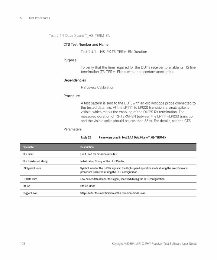
128 Keysight M8085A MIPI C-PHY Receiver Test Software User Guide
5 Test Procedures
Test 2.4.1 Data 0 Lane T_HS-TERM-EN
CTS Test Number and Name
Test 2.4.1 – HS-RX T3-TERM-EN Duration
Purpose
To verify that the time required for the DUT’s receiver to enable its HS line termination (T3-TERM-EN) is within the conformance limits.
Dependencies
HS Levels Calibration
Procedure
A test pattern is sent to the DUT, with an oscilloscope probe connected to the tested data line. At the LP111 to LP000 transition, a small spike is visible, which marks the enabling of the DUT'S Rx termination. The measured duration of T3-TERM-EN between the LP111–LP000 transition and the visible spike should be less than 38ns. For details, see the CTS.
Parameters
Table 52 Parameters used in Test 2.4.1 Data 0 Lane T_HS-TERM-EN
Parameter Description
BER Limit Limit used for bit-error-ratio test.
BER Reader init string Initialization String for the BER Reader.
HS Symbol Rate Symbol Rate for the C-PHY signal in the High-Speed operation mode during the execution of a procedure. Selected during the DUT configuration.
LP Data Rate Low power data rate for the signal, specified during the DUT configuration.
Offline Offline Mode.
Trigger Level Step size for the modification of the common-mode level.
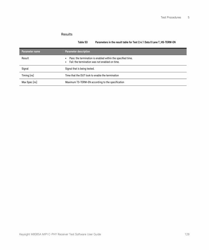
Keysight M8085A MIPI C-PHY Receiver Test Software User Guide 129
Test Procedures 5
Results
Table 53 Parameters in the result table for Test 2.4.1 Data 0 Lane T_HS-TERM-EN
Parameter name Parameter description
Result • Pass: the termination is enabled within the specified time.• Fail: the termination was not enabled on time.
Signal Signal that is being tested.
Timing [ns] Time that the DUT took to enable the termination
Max Spec [ns] Maximum T3-TERM-EN according to the specification
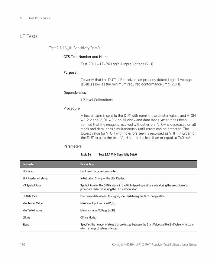
130 Keysight M8085A MIPI C-PHY Receiver Test Software User Guide
5 Test Procedures
LP Tests
Test 2.1.1 V_IH Sensitivity Data0
CTS Test Number and Name
Test 2.1.1 – LP-RX Logic 1 Input Voltage (VIH)
Purpose
To verify that the DUT’s LP receiver can properly detect Logic 1 voltage levels as low as the minimum required conformance limit (V_IH).
Dependencies
LP level Calibrations
Procedure
A test pattern is sent to the DUT with nominal parameter values and V_OH = 1.2 V and V_OL = 0 V on all clock and data lanes. After it has been verified that the image is received without errors, V_OH is decreased on all clock and data lanes simultaneously until errors can be detected. The lowest value for V_OH with no errors seen is recorded as V_IH. In order for the DUT to pass the test, V_IH should be less than or equal to 740 mV.
Parameters
Table 54 Test 2.1.1 V_IH Sensitivity Data0
Parameter Description
BER Limit Limit used for bit-error-ratio test.
BER Reader init string Initialization String for the BER Reader.
HS Symbol Rate Symbol Rate for the C-PHY signal in the High-Speed operation mode during the execution of a procedure. Selected during the DUT configuration.
LP Data Rate Low power data rate for the signal, specified during the DUT configuration.
Max Tested Value Maximum Input Voltage (V_IH)
Min Tested Value Minimum Input Voltage (V_IH)
Offline Offline Mode.
Steps Specifies the number of steps that are tested between the Start Value and the End Value for tests in which a range of values is tested.

Keysight M8085A MIPI C-PHY Receiver Test Software User Guide 131
Test Procedures 5
Results
Table 55 Parameters in the result table for “Test 2.1.1 V_IH Sensitivity Data0”
Parameter name Parameter description
Result • Pass: the minimum V_IH that the DUT can handle without errors is smaller than or equal to the minimum value in the specification.
• Fail: the minimum V_IH that the DUT can handle without errors is larger than the minimum value in the specification.
Min Passed V_IH [mV] Minimum input high-level voltage, VIH, for which the test data was transmitted without errors
Min Tested V_IH [mV] Minimum tested V_IH
Min Spec [mV] Minimum input high-level voltage, VIH, for which the DUT shall receive the data without errors according to the specification
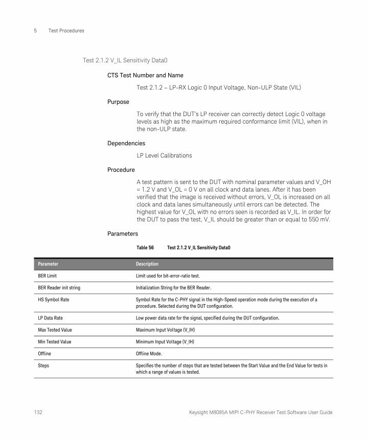
132 Keysight M8085A MIPI C-PHY Receiver Test Software User Guide
5 Test Procedures
Test 2.1.2 V_IL Sensitivity Data0
CTS Test Number and Name
Test 2.1.2 – LP-RX Logic 0 Input Voltage, Non-ULP State (VIL)
Purpose
To verify that the DUT’s LP receiver can correctly detect Logic 0 voltage levels as high as the maximum required conformance limit (VIL), when in the non-ULP state.
Dependencies
LP Level Calibrations
Procedure
A test pattern is sent to the DUT with nominal parameter values and V_OH = 1.2 V and V_OL = 0 V on all clock and data lanes. After it has been verified that the image is received without errors, V_OL is increased on all clock and data lanes simultaneously until errors can be detected. The highest value for V_OL with no errors seen is recorded as V_IL. In order for the DUT to pass the test, V_IL should be greater than or equal to 550 mV.
Parameters
Table 56 Test 2.1.2 V_IL Sensitivity Data0
Parameter Description
BER Limit Limit used for bit-error-ratio test.
BER Reader init string Initialization String for the BER Reader.
HS Symbol Rate Symbol Rate for the C-PHY signal in the High-Speed operation mode during the execution of a procedure. Selected during the DUT configuration.
LP Data Rate Low power data rate for the signal, specified during the DUT configuration.
Max Tested Value Maximum Input Voltage (V_IH)
Min Tested Value Minimum Input Voltage (V_IH)
Offline Offline Mode.
Steps Specifies the number of steps that are tested between the Start Value and the End Value for tests in which a range of values is tested.

Keysight M8085A MIPI C-PHY Receiver Test Software User Guide 133
Test Procedures 5
Results
Table 57 Parameters in the result table for “Test 2.1.2 V_IL Sensitivity Data0”
Parameter name Parameter description
Result • Pass: the minimum V_IH that the DUT can handle without errors is smaller than or equal to the minimum value in the specification.
• Fail: the minimum V_IH that the DUT can handle without errors is larger than the minimum value in the specification.
Max Passed V_IL [mV] Maximum input high-level voltage, VIL, for which the test data was transmitted without errors
Max Tested V_IL [mV] Maximum tested V_IL
Max Spec V_IL [mV] Maximum input high-level voltage, VIL, for which the DUT shall receive the data without errors according to the specification
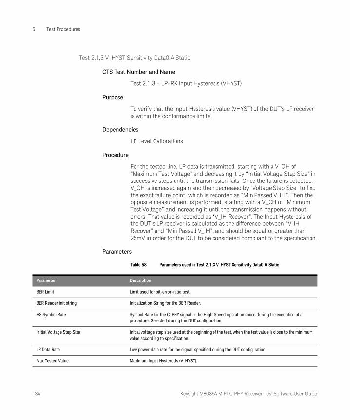
134 Keysight M8085A MIPI C-PHY Receiver Test Software User Guide
5 Test Procedures
Test 2.1.3 V_HYST Sensitivity Data0 A Static
CTS Test Number and Name
Test 2.1.3 – LP-RX Input Hysteresis (VHYST)
Purpose
To verify that the Input Hysteresis value (VHYST) of the DUT’s LP receiver is within the conformance limits.
Dependencies
LP Level Calibrations
Procedure
For the tested line, LP data is transmitted, starting with a V_OH of “Maximum Test Voltage” and decreasing it by “Initial Voltage Step Size” in successive steps until the transmission fails. Once the failure is detected, V_OH is increased again and then decreased by “Voltage Step Size” to find the exact failure point, which is recorded as “Min Passed V_IH”. Then the opposite measurement is performed, starting with a V_OH of “Minimum Test Voltage” and increasing it until the transmission happens without errors. That value is recorded as “V_IH Recover”. The Input Hysteresis of the DUT’s LP receiver is calculated as the difference between “V_IH Recover” and “Min Passed V_IH”, and should be equal or greater than 25mV in order for the DUT to be considered compliant to the specification.
Parameters
Table 58 Parameters used in Test 2.1.3 V_HYST Sensitivity Data0 A Static
Parameter Description
BER Limit Limit used for bit-error-ratio test.
BER Reader init string Initialization String for the BER Reader.
HS Symbol Rate Symbol Rate for the C-PHY signal in the High-Speed operation mode during the execution of a procedure. Selected during the DUT configuration.
Initial Voltage Step Size Initial voltage step size used at the beginning of the test, when the test value is close to the minimum value according to specification.
LP Data Rate Low power data rate for the signal, specified during the DUT configuration.
Max Tested Value Maximum Input Hysteresis (V_HYST).

Keysight M8085A MIPI C-PHY Receiver Test Software User Guide 135
Test Procedures 5
Results
Table 59 Parameters in the result table for “Test 2.1.3 V_HYST Sensitivity Data0 A Static”
Min Tested Value Minimum Input Hysteresis (V_HYST).
Offline Offline Mode.
Voltage Step Size The step size by which the voltage is increased/decreased while running test.
Parameter name Parameter description
Result Pass: the Input Hysteresis value of the DUT’s LP receiver line is within the conformance limits.Fail: the Input Hysteresis value of the DUT’s LP receiver line is not within the conformance limits.
Min Passed V_IH [mV] Minimum V_IH supported by the DUT.
Min Spec V_IH [mV] Minimum V_IH that the DUT must support according to the specification.
V_IH Recover [mV] V_IH value for which the DUT stops reporting errors after it failed.
V_HYST [mV] Actual value of the DUT's V_HYST as measured during the test
Min Spec V_HYST [mV] Minimum V_HYST of the DUT according to the specification.
136 Keysight M8085A MIPI C-PHY Receiver Test Software User Guide
5 Test Procedures
Test 2.1.3 V_HYST Sensitivity Data0 B Static
CTS Test Number and Name, Purpose, Dependencies, Parameters, Results
Same as that for Test 2.1.3 V_HYST Sensitivity Data0 A Static on page 134.
Test 2.1.3 V_HYST Sensitivity Data0 C Static
CTS Test Number and Name, Purpose, Dependencies, Parameters, Results
Same as that for Test 2.1.3 V_HYST Sensitivity Data0 A Static on page 134.
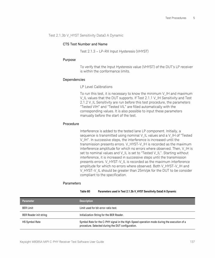
Keysight M8085A MIPI C-PHY Receiver Test Software User Guide 137
Test Procedures 5
Test 2.1.3b V_HYST Sensitivity Data0 A Dynamic
CTS Test Number and Name
Test 2.1.3 – LP-RX Input Hysteresis (VHYST)
Purpose
To verify that the Input Hysteresis value (VHYST) of the DUT’s LP receiver is within the conformance limits.
Dependencies
LP Level Calibrations
To run this test, it is necessary to know the minimum V_IH and maximum V_IL values that the DUT supports. If Test 2.1.1 V_IH Sensitivity and Test 2.1.2 V_IL Sensitivity are run before this test procedure, the parameters “Tested VIH” and “Tested VIL” are filled automatically with the corresponding values. It is also possible to input these parameters manually before the start of the test.
Procedure
Interference is added to the tested lane LP component. Initially, a sequence is transmitted using nominal V_IL values and a V_IH of “Tested V_IH”. In successive steps, the interference is increased until the transmission presents errors. V_HYST-V_IH is recorded as the maximum interference amplitude for which no errors where observed. Then, V_IH is set to nominal values and V_IL is set to “Tested V_IL”. Starting without interference, it is increased in successive steps until the transmission presents errors. V_HYST-V_IL is recorded as the maximum interference amplitude for which no errors where observed. Both V_HYST-V_IH and V_HYST-V_IL should be greater than 25mVpk for the DUT to be consider compliant to the specification.
Parameters
Table 60 Parameters used in Test 2.1.3b V_HYST Sensitivity Data0 A Dynamic
Parameter Description
BER Limit Limit used for bit-error-ratio test.
BER Reader init string Initialization String for the BER Reader.
HS Symbol Rate Symbol Rate for the C-PHY signal in the High-Speed operation mode during the execution of a procedure. Selected during the DUT configuration.

138 Keysight M8085A MIPI C-PHY Receiver Test Software User Guide
5 Test Procedures
Results
Table 61 Parameters in the result table for “Test 2.1.3b V_HYST Sensitivity Data0 A Dynamic”
Interference Frequency Interference frequency used during this test step.
Interference Step Size The step size by which the interference voltage is increased/decreased while running test.
LP Data Rate Low power data rate for the signal, specified during the DUT configuration.
Max Interference Amplitude Maximum interference amplitude for which the DUT was able to receive the test sequence withouterrors for the given common-mode and differential voltage levels.
Offline Offline Mode.
Tested VIH Minimum V_IH supported by the DUT.
Tested VIL Maximum V_IL supported by the DUT.
VIH during VIL test The value obtained by V_IH while running V_IL test.
VIL during VIH test The value obtained by V_IL while running V_IH test.
Parameter name Parameter description
Result Pass: the Input Hysteresis value of the DUT’s LP receiver line is within the conformance limits.Fail: the Input Hysteresis value of the DUT’s LP receiver line is not within the conformance limits.
Max Passed Interference V_IH [mV] Maximum V_IH single ended interference supported by the DUT
Min Failed Interference V_IH [mV] Minimum V_IH single ended interference that caused the DUT to fail
Max Passed Interference V_IL [mV] Maximum V_IL single ended interference supported by the DUT
Min Failed Interference V_IL [mV] Minimum V_IL single ended interference that caused the DUT to fail
Min Spec [mV] Minimum single ended interference that the DUT shall be able to handle according to the specification
Keysight M8085A MIPI C-PHY Receiver Test Software User Guide 139
Test Procedures 5
Test 2.1.3b V_HYST Sensitivity Data0 B Dynamic
CTS Test Number and Name, Purpose, Dependencies, Parameters, Results
Same as that for Test 2.1.3b V_HYST Sensitivity Data0 A Dynamic on page 137.
Test 2.1.3b V_HYST Sensitivity Data0 C Dynamic
CTS Test Number and Name, Purpose, Dependencies, Parameters, Results
Same as that for Test 2.1.3b V_HYST Sensitivity Data0 A Dynamic on page 137.

140 Keysight M8085A MIPI C-PHY Receiver Test Software User Guide
5 Test Procedures
Test 2.1.4 LP-RX Minimum Pulse Width ResponseData0
CTS Test Number and Name
Test 2.1.4 – LP-RX Minimum Pulse Width Response (TMIN-RX)
Purpose
To verify that the DUT’s LP receiver can detect LP pulses with the minimum required duration.
Dependencies
LP level Calibrations
Procedure
An LP test pattern is sent on the lane being tested with the LP pulse width T_LPX slowly decreasing until errors in the received sequence can be observed. In order for the DUT to pass the test, the smallest value for T_LPX for which the sequence can be received without errors should be less than or equal to 20ns.
Parameters
Table 62 Parameters used in Test 2.1.4 LP-RX Minimum Pulse Width ResponseData0
Parameter Description
BER Limit Limit used for bit-error-ratio test.
BER Reader init string Initialization String for the BER Reader.
HS Symbol Rate Symbol Rate for the C-PHY signal in the High-Speed operation mode during the execution of a procedure. Selected during the DUT configuration.
LP Data Rate Low power data rate for the signal, specified during the DUT configuration.
Offline Offline mode.
Steps Specifies the number of steps that are tested between the Start Value and the End Value for tests in which a range of values is tested.
V_OH Output high voltage.
V_OL Output low voltage.

Keysight M8085A MIPI C-PHY Receiver Test Software User Guide 141
Test Procedures 5
Results
Table 63 Parameters in the result data table “Test 2.1.4 LP-RX Minimum Pulse Width Re-sponseData0”
Parameter name Parameter description
Result • Pass: the minimum pulse duration detected by the DUT is smaller than or equal to the specification value.• Fail: the minimum pulse duration detected by the DUT is larger than the specification value.
Min Passed [ns] Minimum pulse duration detected by the DUT
Min Spec [ns] Minimum pulse duration according to the specification.
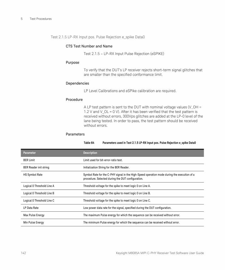
142 Keysight M8085A MIPI C-PHY Receiver Test Software User Guide
5 Test Procedures
Test 2.1.5 LP-RX Input pos. Pulse Rejection e_spike Data0
CTS Test Number and Name
Test 2.1.5 – LP-RX Input Pulse Rejection (eSPIKE)
Purpose
To verify that the DUT’s LP receiver rejects short-term signal glitches that are smaller than the specified conformance limit.
Dependencies
LP Level Calibrations and eSPike calibration are required.
Procedure
A LP test pattern is sent to the DUT with nominal voltage values (V_OH = 1.2 V and V_OL = 0 V). After it has been verified that the test pattern is received without errors, 300Vps glitches are added at the LP-0 level of the lane being tested. In order to pass, the test pattern should be received without errors.
Parameters
Table 64 Parameters used in Test 2.1.5 LP-RX Input pos. Pulse Rejection e_spike Data0
Parameter Description
BER Limit Limit used for bit-error-ratio test.
BER Reader init string Initialization String for the BER Reader.
HS Symbol Rate Symbol Rate for the C-PHY signal in the High-Speed operation mode during the execution of a procedure. Selected during the DUT configuration.
Logical 0 Threshold Line A Threshold voltage for the spike to meet logic 0 on Line A.
Logical 0 Threshold Line B Threshold voltage for the spike to meet logic 0 on Line B.
Logical 0 Threshold Line C Threshold voltage for the spike to meet logic 0 on Line C.
LP Data Rate Low power data rate for the signal, specified during the DUT configuration.
Max Pulse Energy The maximum Pulse energy for which the sequence can be received without error.
Min Pulse Energy The minimum Pulse energy for which the sequence can be received without error.

Keysight M8085A MIPI C-PHY Receiver Test Software User Guide 143
Test Procedures 5
Results
Table 65 Parameters in the result data table “Test 2.1.5 LP-RX Input pos. Pulse Rejection e_spike Data0”
Offline Offline Mode.
Positive Spikes Positive Input pulse rejection.
Steps Specifies the number of steps that are tested between the Start Value and the End Value for tests in which a range of values is tested.
Parameter name Parameter description
Result • Pass: the DUT’s LP receiver rejects short-term signal glitches that are smaller than the specified conformance limit.
• Fail: the DUT’s LP receiver does not reject short-term signal glitches that are smaller than the specified conformance limit.
Set Transition Time [ns] e-Spike rise time needed to achieve the desired glitch depth.
Max Passed [pVs] Maximum glitch width tolerated by the DUT.
Max Spec [pVs] Maximum glitch width that the DUT must tolerate according to the specification.

144 Keysight M8085A MIPI C-PHY Receiver Test Software User Guide
5 Test Procedures
Test 2.1.5 LP-RX Input neg. Pulse Rejection e_spike Data0
CTS Test Number and Name
Test 2.1.5 – LP-RX Input Pulse Rejection (eSPIKE)
Purpose
To verify that the DUT’s LP receiver rejects short-term signal glitches that are smaller than the specified conformance limit.
Dependencies
LP Level Calibrations and eSPike calibration are required.
Procedure
A LP test pattern is sent to the DUT with V_OH = 880mV and V_OL = 550mV. After it has been verified that the test pattern is received without errors, negative 300Vps glitches are added at the LP-1 level of the tested lane. In order for the DUT to pass the test, the test pattern should be received without errors.
Parameters
Table 66 Parameters used in Test 2.1.5 LP-RX Input neg. Pulse Rejection e_spike Data0
Parameter Description
BER Limit Limit used for bit-error-ratio test.
BER Reader init string Initialization String for the BER Reader.
HS Symbol Rate Symbol Rate for the C-PHY signal in the High-Speed operation mode during the execution of a procedure. Selected during the DUT configuration.
Logical 1 Threshold Line A Threshold voltage for the spike to meet logic 1 on Line A.
Logical 1 Threshold Line B Threshold voltage for the spike to meet logic 1 on Line B.
Logical 1 Threshold Line C Threshold voltage for the spike to meet logic 1 on Line C.
LP Data Rate Low power data rate for the signal, specified during the DUT configuration.
Max Pulse Energy The maximum Pulse energy for which the sequence can be received without error.
Min Pulse Energy The minimum Pulse energy for which the sequence can be received without error.
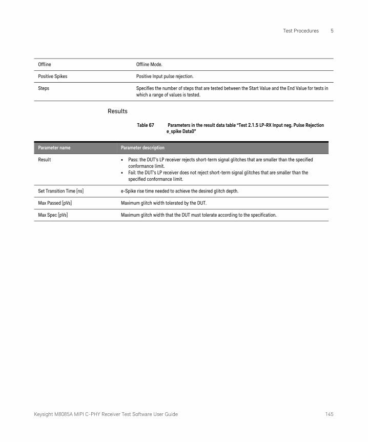
Keysight M8085A MIPI C-PHY Receiver Test Software User Guide 145
Test Procedures 5
Results
Table 67 Parameters in the result data table “Test 2.1.5 LP-RX Input neg. Pulse Rejection e_spike Data0”
Offline Offline Mode.
Positive Spikes Positive Input pulse rejection.
Steps Specifies the number of steps that are tested between the Start Value and the End Value for tests in which a range of values is tested.
Parameter name Parameter description
Result • Pass: the DUT’s LP receiver rejects short-term signal glitches that are smaller than the specified conformance limit.
• Fail: the DUT’s LP receiver does not reject short-term signal glitches that are smaller than the specified conformance limit.
Set Transition Time [ns] e-Spike rise time needed to achieve the desired glitch depth.
Max Passed [pVs] Maximum glitch width tolerated by the DUT.
Max Spec [pVs] Maximum glitch width that the DUT must tolerate according to the specification.
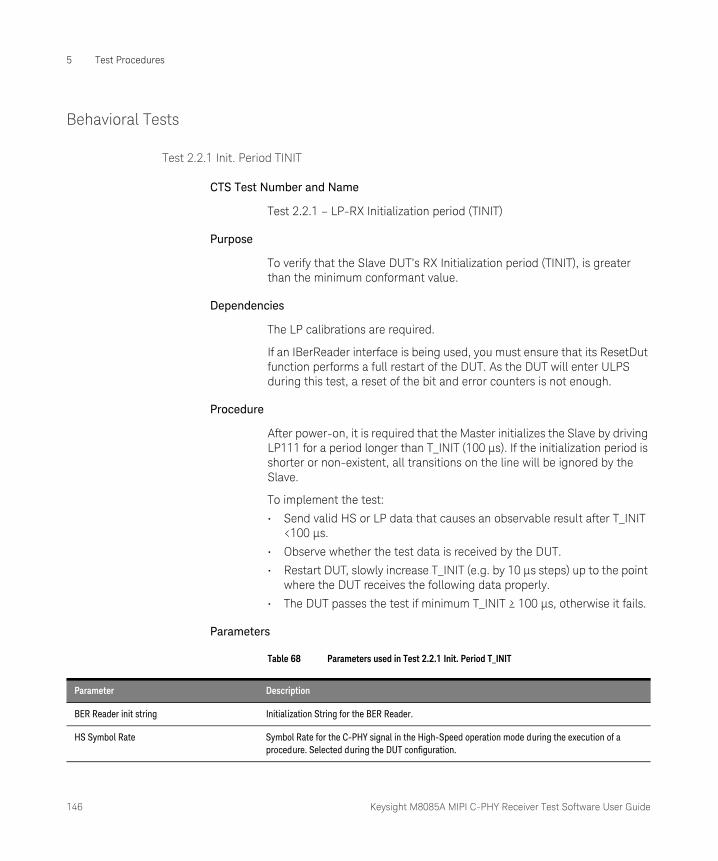
146 Keysight M8085A MIPI C-PHY Receiver Test Software User Guide
5 Test Procedures
Behavioral Tests
Test 2.2.1 Init. Period TINIT
CTS Test Number and Name
Test 2.2.1 – LP-RX Initialization period (TINIT)
Purpose
To verify that the Slave DUT’s RX Initialization period (TINIT), is greater than the minimum conformant value.
Dependencies
The LP calibrations are required.
If an IBerReader interface is being used, you must ensure that its ResetDut function performs a full restart of the DUT. As the DUT will enter ULPS during this test, a reset of the bit and error counters is not enough.
Procedure
After power-on, it is required that the Master initializes the Slave by driving LP111 for a period longer than T_INIT (100 µs). If the initialization period is shorter or non-existent, all transitions on the line will be ignored by the Slave.
To implement the test:
• Send valid HS or LP data that causes an observable result after T_INIT <100 µs.
• Observe whether the test data is received by the DUT.
• Restart DUT, slowly increase T_INIT (e.g. by 10 µs steps) up to the point where the DUT receives the following data properly.
• The DUT passes the test if minimum T_INIT ≥ 100 µs, otherwise it fails.
Parameters
Table 68 Parameters used in Test 2.2.1 Init. Period T_INIT
Parameter Description
BER Reader init string Initialization String for the BER Reader.
HS Symbol Rate Symbol Rate for the C-PHY signal in the High-Speed operation mode during the execution of a procedure. Selected during the DUT configuration.
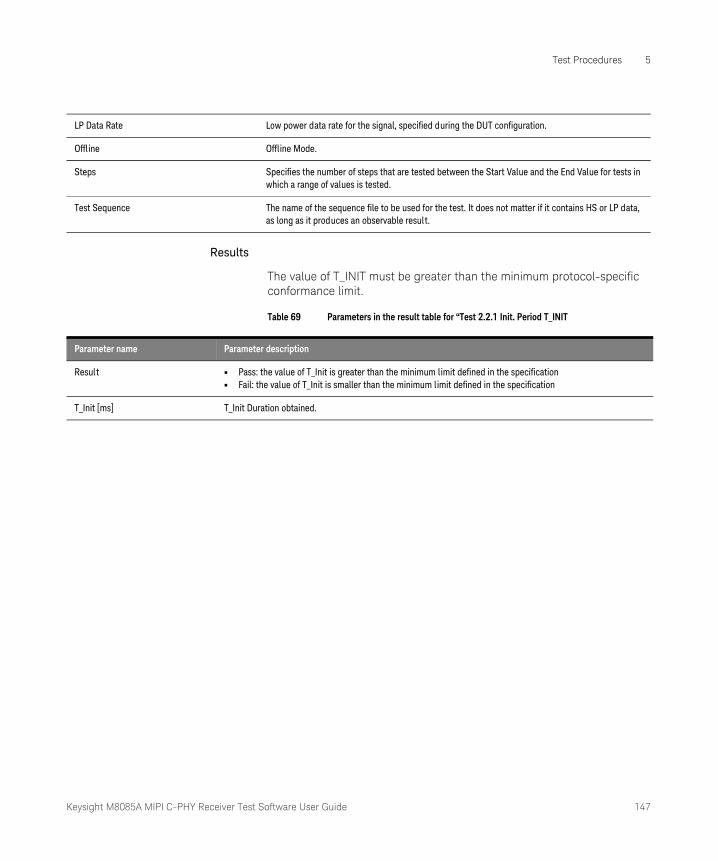
Keysight M8085A MIPI C-PHY Receiver Test Software User Guide 147
Test Procedures 5
Results
The value of T_INIT must be greater than the minimum protocol-specific conformance limit.
Table 69 Parameters in the result table for “Test 2.2.1 Init. Period T_INIT
LP Data Rate Low power data rate for the signal, specified during the DUT configuration.
Offline Offline Mode.
Steps Specifies the number of steps that are tested between the Start Value and the End Value for tests in which a range of values is tested.
Test Sequence The name of the sequence file to be used for the test. It does not matter if it contains HS or LP data, as long as it produces an observable result.
Parameter name Parameter description
Result • Pass: the value of T_Init is greater than the minimum limit defined in the specification• Fail: the value of T_Init is smaller than the minimum limit defined in the specification
T_Init [ms] T_Init Duration obtained.
148 Keysight M8085A MIPI C-PHY Receiver Test Software User Guide
5 Test Procedures
Test 2.2.2 ULPS Exit TWAKEUP
CTS Test Number and Name
Test 2.2.2 – ULPS Exit: LP-RX TWAKEUP Timer Value
Purpose
To verify that the DUT’s LP receiver properly exits ULPS when sent a Mark-1 for minimum time (TWAKEUP) followed by a Stop state.
Dependencies
The LP calibrations are required.
If an IBerReader interface is being used, you must ensure that its ResetDut function performs a full restart of the DUT. As the DUT will enter ULPS during this test, a reset of the bit and error counters is not enough.
Procedure
When in ULPS, the Slave should wait for an Exit Sequence formed by a Mark-1 State (LP100) with a minimum duration of T_Wakeup = 1 ms followed by a Stop State (LP111).
To implement the test:
• Set DUT to ULPS by using the sequence file named “ULPS Entry Sequence” in the test properties.
• Verify that the DUT is in ULPS by sending a valid HS pattern. If it's not received, it means the DUT is in ULPS. If the test pattern is received, the test reports a failure because it was not possible to put the DUT into ULPS.
• Load “ULPS Entry and Exit Sequence”. This sequence shall put the DUT into ULPS as “ULPS Entry Sequence”, and shall also contain a block called “ULPSExit”, that will be used by the automation to slowly increase the Mark-1 duration.
• In Compliance Mode, send Sequence with T_Wakeup = 1 ms followed by valid HS data and see if the DUT left ULPS mode or not.
• In Expert mode, sweep from Minimum Tested Value to Maximum Tested Value until the DUT leaves ULPS. Record T_Wakeup time.
• If T_Wakeup smaller or equal than 1 ms the DUT has passed the test, otherwise it has failed.

Keysight M8085A MIPI C-PHY Receiver Test Software User Guide 149
Test Procedures 5
Parameters
Table 70 Parameters used in Test 2.2.2 ULPS Exit TWakeup
Results
The DUT must exit the ULPS mode.
Table 71 Parameters in the result table for “Test 2.2.2 ULPS Exit TWakeup”
Parameter Description
BER Reader init string Initialization String for the BER Reader.
HS Symbol Rate Symbol Rate for the C-PHY signal in the High-Speed operation mode during the execution of a procedure. Selected during the DUT configuration.
LP Data Rate Low power data rate for the signal, specified during the DUT configuration.
Offline Offline Mode.
Steps Specifies the number of steps that are tested between the Start Value and the End Value for tests in which a range of values is tested.
ULPS Entry and exit Sequence A ULPS entry sequence is sent to the DUT, followed by a Mark-1/Stop plus a valid HS burst on all lanes using nominal voltage levels. ULP Exit Sequence.is active high signal, asserted when ULP state is active and the protocol is ready to leave ULP state.
ULPS Entry Sequence A ULPS entry sequence is sent to the DUT, followed by a Mark-1/Stop plus a valid HS burst on all lanes using nominal voltage levels.
Parameter name Parameter description
Result • Pass: the value of T_Wakeup is greater than or equal to the minimum limit defined in the specification.
• Fail: the value of T_ Wakeup is smaller than the minimum limit defined in the specification.
T_WakeUP [ms] Time that a transmitter drives a Mark-1 state prior to a Stop state in order to initiate an exit from ULPS.
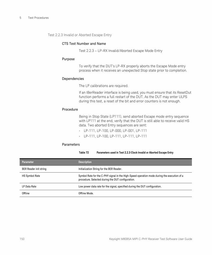
150 Keysight M8085A MIPI C-PHY Receiver Test Software User Guide
5 Test Procedures
Test 2.2.3 Invalid or Aborted Escape Entry
CTS Test Number and Name
Test 2.2.3 – LP-RX Invalid/Aborted Escape Mode Entry
Purpose
To verify that the DUT’s LP-RX properly aborts the Escape Mode entry process when it receives an unexpected Stop state prior to completion.
Dependencies
The LP calibrations are required.
If an IBerReader interface is being used, you must ensure that its ResetDut function performs a full restart of the DUT. As the DUT may enter ULPS during this test, a reset of the bit and error counters is not enough.
Procedure
Being in Stop State (LP111), send aborted Escape mode entry sequence with LP111 at the end, verify that the DUT is still able to receive valid HS data. Two aborted Entry sequences are sent:
• LP-111, LP-100, LP-000, LP-001, LP-111
• LP-111, LP-100, LP-111, LP-111, LP-111
Parameters
Table 72 Parameters used in Test 2.2.3 Clock Invalid or Aborted Escape Entry
Parameter Description
BER Reader init string Initialization String for the BER Reader.
HS Symbol Rate Symbol Rate for the C-PHY signal in the High-Speed operation mode during the execution of a procedure. Selected during the DUT configuration.
LP Data Rate Low power data rate for the signal, specified during the DUT configuration.
Offline Offline Mode.

Keysight M8085A MIPI C-PHY Receiver Test Software User Guide 151
Test Procedures 5
Results
In both cases, the integrity of the received data, as well as the overall operation of the DUT must not negatively affected by the presence of the invalid ULPS Entry sequences.
Table 73 Parameters in the result table for “Test 2.2.3 Clock Invalid or Aborted Escape Entry”
Parameter name Parameter description
Result • Pass: the test data was received by the DUT, which therefore, did not enter ULPS.• Fail: the test data was not received by the DUT.
Test Pattern The final bit pattern received by the DUT.

152 Keysight M8085A MIPI C-PHY Receiver Test Software User Guide
5 Test Procedures
Test 2.2.4 Invalid or Aborted Escape Command
CTS Test Number and Name
Test 2.2.4 – LP-RX Invalid/Aborted Escape Mode Command
Purpose
To verify that the DUT’s LP-RX properly ignores invalid or aborted Escape commands.
Dependencies
The LP calibrations are required. If an IBerReader interface is being used, please make sure that its ResetDut function performs a full restart of the DUT. As the DUT may enter ULPS during this test, a reset of the bit and error counters is not enough.
Procedure
Send an invalid Escape Mode Entry sequence follwed by and aborted Escape command, verify that the DUT still receives the valid HS data that we send afterwards. The command is aborted by adding LP111 states in its final bits. The CTS defines the following test cases:
1 [Valid EM Entry] + LP-001/000/001/000/001/000/100/000/100/000/100/000/100/000/001/111 + [Stop]
2 [Valid EM Entry] + LP-001/000/001/000/001/000/100/000/100/000/100/000/100/111/111/111 + [Stop]
3 [Valid EM Entry] + LP-001/000/001/000/001/000/100/000/100/000/100/111/111/111/111/111 + [Stop]
4 [Valid EM Entry] + LP-001/000/001/000/001/000/100/000/100/111/111/111/111/111/111/111 + [Stop]
5 [Valid EM Entry] + LP-001/000/001/000/001/000/100/111/111/111/111/111/111/111/111/111 + [Stop]
NOTEThis test is considered as informative in CTS, the result graph cannot be drawn from the behavior of the DUT during the test run.
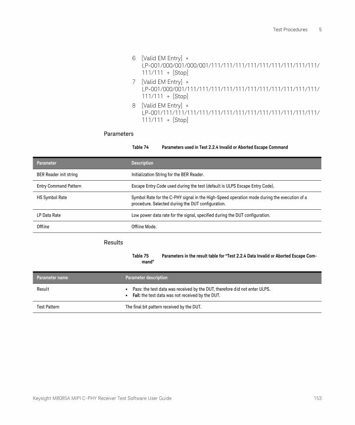
Keysight M8085A MIPI C-PHY Receiver Test Software User Guide 153
Test Procedures 5
6 [Valid EM Entry] + LP-001/000/001/000/001/111/111/111/111/111/111/111/111/111/111/111 + [Stop]
7 [Valid EM Entry] + LP-001/000/001/111/111/111/111/111/111/111/111/111/111/111/111/111 + [Stop]
8 [Valid EM Entry] + LP-001/111/111/111/111/111/111/111/111/111/111/111/111/111/111/111 + [Stop]
Parameters
Table 74 Parameters used in Test 2.2.4 Invalid or Aborted Escape Command
Results
Table 75 Parameters in the result table for “Test 2.2.4 Data Invalid or Aborted Escape Com-mand”
Parameter Description
BER Reader init string Initialization String for the BER Reader.
Entry Command Pattern Escape Entry Code used during the test (default is ULPS Escape Entry Code).
HS Symbol Rate Symbol Rate for the C-PHY signal in the High-Speed operation mode during the execution of a procedure. Selected during the DUT configuration.
LP Data Rate Low power data rate for the signal, specified during the DUT configuration.
Offline Offline Mode.
Parameter name Parameter description
Result • Pass: the test data was received by the DUT, therefore did not enter ULPS.• Fail: the test data was not received by the DUT.
Test Pattern The final bit pattern received by the DUT.
154 Keysight M8085A MIPI C-PHY Receiver Test Software User Guide
5 Test Procedures
Test 2.2.5 Post-Trigger-Command
CTS Test Number and Name
Test 2.2.5 – LP-RX Escape Mode, Ignoring of Post-Trigger-Command Extra Bits
Purpose
To verify that the DUT’s LP-RX ignores any extra bits received following a Trigger Command.
Dependencies
The LP calibrations are required.
If an IBerReader interface is being used, you must ensure that its ResetDut function performs a full restart of the DUT. As the DUT may enter ULPS during this test, a reset of the bit and error counters is not enough.
Procedure
An Escape mode sequence containing a Trigger sequence followed by extra post-command bits, which is a combination of an extra byte of data after the Trigger command, and the ULPS Entry command as an extra byte is used. The invalid ULPS command byte should be ignored by the DUT.
To implement the test:
• Click Run to transmit a test sequence to the DUT. Refer to Running Tests on page 26 to know how to run procedures.
• For each of the available Trigger commands (Reset-Trigger, Unknown-3, Unknown-4, Unknown-5), send the appropriate Escape Mode Entry + Trigger Command + Stop State, interleaving a ULPS Entry command between the Trigger Command and the Stop State.
• Send valid data.
• Verify that valid data is received at the DUT.
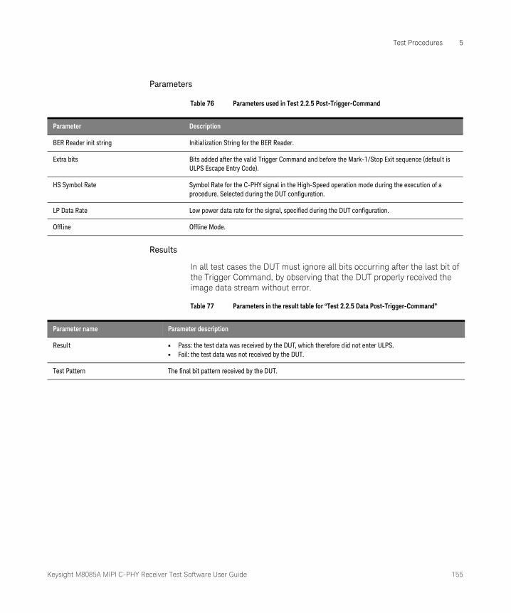
Keysight M8085A MIPI C-PHY Receiver Test Software User Guide 155
Test Procedures 5
Parameters
Table 76 Parameters used in Test 2.2.5 Post-Trigger-Command
Results
In all test cases the DUT must ignore all bits occurring after the last bit of the Trigger Command, by observing that the DUT properly received the image data stream without error.
Table 77 Parameters in the result table for “Test 2.2.5 Data Post-Trigger-Command”
Parameter Description
BER Reader init string Initialization String for the BER Reader.
Extra bits Bits added after the valid Trigger Command and before the Mark-1/Stop Exit sequence (default is ULPS Escape Entry Code).
HS Symbol Rate Symbol Rate for the C-PHY signal in the High-Speed operation mode during the execution of a procedure. Selected during the DUT configuration.
LP Data Rate Low power data rate for the signal, specified during the DUT configuration.
Offline Offline Mode.
Parameter name Parameter description
Result • Pass: the test data was received by the DUT, which therefore did not enter ULPS.• Fail: the test data was not received by the DUT.
Test Pattern The final bit pattern received by the DUT.
156 Keysight M8085A MIPI C-PHY Receiver Test Software User Guide
5 Test Procedures
Test 2.2.6 Data Lane LP-RX Escape Mode Unsupported or Unassigned Commands
CTS Test Number and Name
Test 2.2.6 – LP-RX Escape Mode Unsupported/Unassigned Commands
Purpose
To verify that the DUT’s LP-RX properly ignores unsupported and unassigned Escape Mode commands.
An Entry Command Pattern consists of 8 bits, therefore there are 256 possible combinations. Of these, one is assigned to the Low-Power Data Transmission Mode (11100001), one to the Ultra-Low-Power State Mode (00011110) and one to the Reset Trigger (01100010). The remaining 253 combinations are either Undefined modes (2), Unknown triggers (3), or Unassigned (248), and shall be ignored by the DUT. This test verifies that all Unsupported and Unassigned commands are ignored by the DUT.
Dependencies
The LP calibrations are required.
If an IBerReader interface is being used, you must ensure that its ResetDut function performs a full restart of the DUT. As the DUT may enter ULPS during this test, a reset of the bit and error counters is not enough.
Procedure
An Escape mode sequence containing an unassigned Escape Command, which is combination of 248 unassigned command codes, is used. The invalid undefined/unknown/unassigned command codes should be ignored by the DUT.
To implement the test:
• For each of the remaining 253 combinations, send the appropriate Escape Mode Entry + an Undefined/Unknown/Unassigned Command + Stop State.
• Send valid data.
• Verify that valid data is received at the DUT

Keysight M8085A MIPI C-PHY Receiver Test Software User Guide 157
Test Procedures 5
Parameters
Table 78 Parameters used in Test 2.2.6 Data Lane LP-RX Escape Mode Unsupported or Unas-signed Commands
Results
For all test cases, the DUT must ignore the unsupported/unassigned command, and successfully receives the image data stream.
Table 79 Parameters in the result table for “Test 2.2.6 Data Lane LP-RX Escape Mode Unsup-ported or Unassigned Commands”
Parameter Description
BER Reader init string Initialization String for the BER Reader.
HS Symbol Rate Symbol Rate for the C-PHY signal in the High-Speed operation mode during the execution of a procedure. Selected during the DUT configuration.
LP Data Rate Low power data rate for the signal, specified during the DUT configuration.
Offline Offline Mode.
Parameter name Parameter description
Result • Pass: the test data was received by the DUT, which therefore did not enter ULPS.• Fail: the test data was not received by the DUT.
Test Pattern The final bit pattern received by the DUT.

158 Keysight M8085A MIPI C-PHY Receiver Test Software User Guide
5 Test Procedures

Keysight M8085A MIPI C-PHY Receiver Test Software
User Guide
6 SCPI Plug-in Interface
Architecture of a plug-in / sub-model concept / 160Sorting and Using the SCPI Commands / 161SCPI Commands / 171
Description of already generated generic commands for plug-ins adapted to the new requirements based on the sub-model approach.
The structure of an identifier attached to a SCPI command contains now additional delimiter. A full qualified identifier has following structure:
‘PluginName#SubModel:Location&FunctionalBlock.Parameter’
In many cases it is not necessary to add a full qualified identifier to every SCPI command. For example a plug-in is implemented a singleton or a location/parameter exists on once. Later on a detailed description will explain the usage and simplification of an identifier that comes along with a SCPI command for addressing plug-ins / sub-models / parameters and so on.
The identifier appended to every SCPI command should be optional to avoid SCPI commands like :PLUGin:rootnode:BREak ‘ ’ // empty identifier
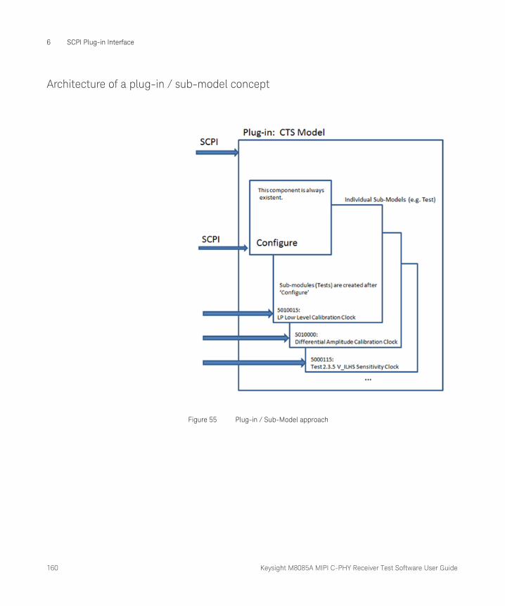
160 Keysight M8085A MIPI C-PHY Receiver Test Software User Guide
6 SCPI Plug-in Interface
Architecture of a plug-in / sub-model concept
Figure 55 Plug-in / Sub-Model approach
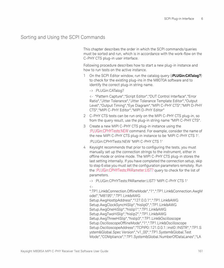
Keysight M8085A MIPI C-PHY Receiver Test Software User Guide 161
SCPI Plug-in Interface 6
Sorting and Using the SCPI Commands
This chapter describes the order in which the SCPI commands/queries must be sorted and run, which is in accordance with the work-flow on the C-PHY CTS plug-in user interface.
Following procedure describes how to start a new plug-in instance and how to run tests on the active instance.
1 On the SCPI Editor window, run the catalog query (:PLUGin:CATalog?) to check for the existing plug-ins in the M8070A software and to identify the correct plug-in string name.
-> :PLUGin:CATalog?
<- "Pattern Capture","Script Editor","DUT Control Interface","Error Ratio","Jitter Tolerance","Jitter Tolerance Template Editor","Output Level","Output Timing","Eye Diagram","MIPI C-PHY CTS","MIPI D-PHY CTS","MIPI C-PHY Editor","MIPI D-PHY Editor"
2 C-PHY CTS tests can be run only on the MIPI C-PHY CTS plug-in, so from the query result, use the plug-in string name "MIPI C-PHY CTS".
3 Create a new MIPI C-PHY CTS plug-in instance using the :PLUGin:CPHYTests:NEW command. For example, consider the name of the new MIPI C-PHY CTS plug-in instance to be 'MIPI C-PHY CTS 1'.
:PLUGin:CPHYTests:NEW 'MIPI C-PHY CTS 1'
4 Keysight recommends that prior to configuring the tests, you must manually set up the connection strings to the instrument, either in offline mode or online mode. The MIPI C-PHY CTS plug-in stores the last setting internally. If you have completed the connection setup, skip to step 6 else you must set the configuration parameters remotely. Run the :PLUGin:CPHYTests:PARameter:LIST? query to check for the list of parameters.
-> :PLUGin:CPHYTests:PARameter:LIST? 'MIPI C-PHY CTS 1'
<- ":TP1.Link&Connection.OfflineMode","1",":TP1.Link&Connection.AwgModel","M8195",":TP1.Link&AWG Setup.AwgHostIpAddress","127.0.0.1",":TP1.Link&AWG Setup.AwgClockSyncHiSlip","hislip0",":TP1.Link&AWG Setup.AwgOneHiSlip","hislip1",":TP1.Link&AWG Setup.AwgTwoHiSlip","hislip2",":TP1.Link&AWG Setup.AwgThreeHiSlip","hislip3",":TP1.Link&Oscilloscope Setup.OscilloscopeOfflineMode","1",":TP1.Link&Oscilloscope Setup.OscilloscopeAddress","TCPIP0::121.0.0.1::inst0::INSTR",":TP1.System&Global.Spec Version","v1_00",":TP1.System&Global.Test Mode","COMpliance",":TP1.System&Global.NumberOfDataLanes","LA

162 Keysight M8085A MIPI C-PHY Receiver Test Software User Guide
6 SCPI Plug-in Interface
NE1",":TP1.System&Global.Custom BER Reader Address","",":TP1.System&Global.MIPI BER Reader","OFFline",":TP1.System&Global.BER Limit","_1_10",":TP1.System&Global.HS Symbol Rate","2500000000",":TP1.System&Global.LP Data Rate","10000000",":TP1.System&Global.LP Transition Time","2.0000000000000001E-09",":TP1.System&Global.Manual Deskew","0",":TP1.System&Global.Triggered Start","0",":TP1.System&Global.HS Sequence Loop File","CPhyCompliance.seq",":TP1.System&Global.LP Sequence Loop File","CPhyLsCompliance.seq",":TP1.System&Global.Behavioral Sequence File","CPhyBehavioral.seq",":TP1.System&Global.Re-Init Sequence before reset DUT","0",":TP1.System&Global.Re-Init Sequence after reset DUT","0",":TP1.System&Global.Mipi Protocol","DSI",":TP1.System&Levels.HS High Level","0.29999999999999999",":TP1.System&Levels.HS Mid Level","0.20000000000000001",":TP1.System&Levels.HS Low Level","0.10000000000000001",":TP1.System&Levels.LP High Level","1.2",":TP1.System&Levels.LP Low Level","0",":TP1.System&Timings.T3-PREPARE","9.9999999999999995E-08",":TP1.System&Timings.T3-PREBEGIN","3333333",":TP1.System&Timings.T3-PREEND","3333333",":TP1.System&Timings.T3-PROGSEQ","",":TP1.System&Timings.T3-SYNC","3444443",":TP1.System&Timings.T3-POST","4444444",":TP1.System&Timings.TX-HS-EXIT","1.9999999999999999E-07",":TP1.System&Timings.TX-WAKEUP","0.001",":TP1.System&Timings.TX-INIT","9.9999999999999995E-07",":TP1.System&Timings.SetDefault","",":TP1.System&Idle Voltage.Idle Voltage","0.29999999999999999"
If you wish to find the parameters associated with a specific calibration / test, run this command with the identifiers written in the following manner:
-> :PLUGin:CPHYTests:PARameter:LIST? 'MIPI C-PHY CTS 1#Test 2.3.3 Jitter Tolerance Data0'
<- ":TP1.System&Acquisition Parameters.PropertiesEditable","1",":TP1.System&Test 2.3.3 Jitter Tolerance Data0.Offline","1",":TP1.System&Test 2.3.3 Jitter Tolerance Data0.BER Reader init string","Data0_HS",":TP1.System&Test 2.3.3 Jitter Tolerance Data0.Steps","2",":TP1.System&Test 2.3.3 Jitter Tolerance Data0.BER Limit","1E-10",":TP1.System&Test 2.3.3 Jitter Tolerance Data0.HS Symbol Rate","2500000000",":TP1.System&Test 2.3.3 Jitter Tolerance Data0.LP Data Rate","10000000",":TP1.System&Test 2.3.3 Jitter Tolerance Data0.Eye Closure Target","0.13500000000000001",":TP1.System&Test 2.3.3 Jitter Tolerance Data0.Six Port S-Parameter

Keysight M8085A MIPI C-PHY Receiver Test Software User Guide 163
SCPI Plug-in Interface 6
File","SParam.s6p",":TP1.System&Test 2.3.3 Jitter Tolerance Data0.SJ Frequency","1125000000",":TP1.System&Test 2.3.3 Jitter Tolerance Data0.SJ Amplitude","0",":TP1.System&Test 2.3.3 Jitter Tolerance Data0.ISI","0.185",":TP1.System&Test 2.3.3 Jitter Tolerance Data0.Eye Height Target","0.040000000000000001",":TP1.System&Test 2.3.3 Jitter Tolerance Data0.Eye Width Target","0.5",":TP1.System&Test 2.3.3 Jitter Tolerance Data0.Minimum Tested Common Mode","0.17499999999999999",":TP1.System&Test 2.3.3 Jitter Tolerance Data0.Maximum Tested Common Mode","0.31"
5 To set up / modify the value for one or more parameters, run the :PLUGin:CPHYTests:PARameter[:Value][?] command.
:PLUGin:CPHYTests:PARameter "MIPI C-PHY CTS 1#:TP1.System&Global.HS Symbol Rate","12E+8"
6 Once all parameters are configured, run the :PLUGin:CPHYTests:CONFigure command. Based on your configuration, the list of calibrations and tests are created and the plug-in is ready to run the CTS tests.
7 To check the list of available calibrations and tests, run the :PLUGin:CPHYTests:LIST? query.
-> :PLUGin:CPHYTests:LIST?
<- "Amplifier Level Calibration Module 1 Gen 1","Amplifier Level Calibration Module 1 Gen 2","Amplifier Level Calibration Module 2 Gen 1","Skew Calibration Module 1","Inter Module Skew Calibration","LP Level Calibration High Data0 A","LP Level Calibration Low Data0 A","LP Level Calibration High Data0 B","LP Level Calibration Low Data0 B","LP Level Calibration High Data0 C","LP Level Calibration Low Data0 C","e-Spike Calibration Data0 A","HS Level Calibration Data0 A","HS Level Calibration Data0 B","HS Level Calibration Data0 C","TRTF Calibration 2500 MSps","ISI Calibration 2500 MSps","SJ Calibration 2500 MSps","DCD Calibration 2500 MSps","Eye Opening Calibration 2500 MSps","Test 2.3.1 Amplitude Tolerance Data0","Test 2.3.2 V_IDTH and V_IDTL Sensitivity Data0","Test 2.3.3 Jitter Tolerance Data0","Test 2.4.2 T_HS-Prepare - Data0 Procedure","Test 2.4.3 T_HS-PreBegin - Data0 Procedure","Test 2.4.4 T_HS-ProgSeq - Data0 Procedure","Test 2.4.5 T_HS-Post - Data0 Procedure","Test 2.4.1 Data0 Lane T_HS-TERM-EN","Test 2.1.1 V_IH Sensitivity Data0","Test 2.1.2 V_IL Sensitivity Data0","Test 2.1.3 V_HYST Sensitivity Data0 A Static","Test 2.1.3 V_HYST Sensitivity Data0 B Static","Test 2.1.3 V_HYST Sensitivity Data0 C Static","Test 2.1.3b V_HYST Sensitivity Data0 A Dynamic","Test 2.1.3b V_HYST Sensitivity Data0 B Dynamic","Test 2.1.3b V_HYST Sensitivity Data0 C Dynamic","Test 2.1.4 LP-RX Minimum Pulse Width ResponseData0","Test 2.1.5 LP-RX Input pos. Pulse Rejection e_spike Data0","Test 2.1.5 LP-RX Input neg.
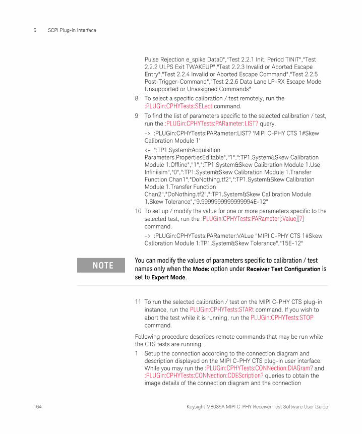
164 Keysight M8085A MIPI C-PHY Receiver Test Software User Guide
6 SCPI Plug-in Interface
Pulse Rejection e_spike Data0","Test 2.2.1 Init. Period TINIT","Test 2.2.2 ULPS Exit TWAKEUP","Test 2.2.3 Invalid or Aborted Escape Entry","Test 2.2.4 Invalid or Aborted Escape Command","Test 2.2.5 Post-Trigger-Command","Test 2.2.6 Data Lane LP-RX Escape Mode Unsupported or Unassigned Commands"
8 To select a specific calibration / test remotely, run the :PLUGin:CPHYTests:SELect command.
9 To find the list of parameters specific to the selected calibration / test, run the :PLUGin:CPHYTests:PARameter:LIST? query.
-> :PLUGin:CPHYTests:PARameter:LIST? 'MIPI C-PHY CTS 1#Skew Calibration Module 1'
<- ":TP1.System&Acquisition Parameters.PropertiesEditable","1",":TP1.System&Skew Calibration Module 1.Offline","1",":TP1.System&Skew Calibration Module 1.Use Infiniisim","0",":TP1.System&Skew Calibration Module 1.Transfer Function Chan1","DoNothing.tf2",":TP1.System&Skew Calibration Module 1.Transfer Function Chan2","DoNothing.tf2",":TP1.System&Skew Calibration Module 1.Skew Tolerance","9.9999999999999994E-12"
10 To set up / modify the value for one or more parameters specific to the selected test, run the :PLUGin:CPHYTests:PARameter[:Value][?] command.
-> :PLUGin:CPHYTests:PARameter:VALue "MIPI C-PHY CTS 1#Skew Calibration Module 1:TP1.System&Skew Tolerance","15E-12"
11 To run the selected calibration / test on the MIPI C-PHY CTS plug-in instance, run the PLUGin:CPHYTests:STARt command. If you wish to abort the test while it is running, run the PLUGin:CPHYTests:STOP command.
Following procedure describes remote commands that may be run while the CTS tests are running.
1 Setup the connection according to the connection diagram and description displayed on the MIPI C-PHY CTS plug-in user interface. While you may run the :PLUGin:CPHYTests:CONNection:DIAGram? and :PLUGin:CPHYTests:CONNection:CDEScription? queries to obtain the image details of the connection diagram and the connection
NOTEYou can modify the values of parameters specific to calibration / test names only when the Mode: option under Receiver Test Configuration is set to Expert Mode.
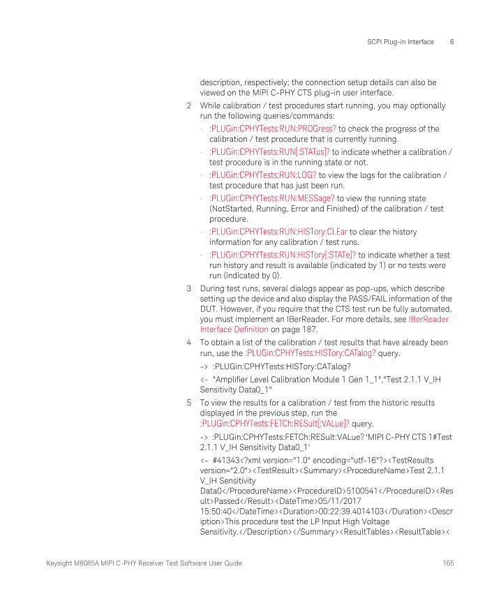
Keysight M8085A MIPI C-PHY Receiver Test Software User Guide 165
SCPI Plug-in Interface 6
description, respectively; the connection setup details can also be viewed on the MIPI C-PHY CTS plug-in user interface.
2 While calibration / test procedures start running, you may optionally run the following queries/commands:
• :PLUGin:CPHYTests:RUN:PROGress? to check the progress of the calibration / test procedure that is currently running.
• :PLUGin:CPHYTests:RUN[:STATus]? to indicate whether a calibration / test procedure is in the running state or not.
• :PLUGin:CPHYTests:RUN:LOG? to view the logs for the calibration / test procedure that has just been run.
• :PLUGin:CPHYTests:RUN:MESSage? to view the running state (NotStarted, Running, Error and Finished) of the calibration / test procedure.
• :PLUGin:CPHYTests:RUN:HISTory:CLEar to clear the history information for any calibration / test runs.
• :PLUGin:CPHYTests:RUN:HISTory[:STATe]? to indicate whether a test run history and result is available (indicated by 1) or no tests were run (indicated by 0).
3 During test runs, several dialogs appear as pop-ups, which describe setting up the device and also display the PASS/FAIL information of the DUT. However, if you require that the CTS test run be fully automated, you must implement an IBerReader. For more details, see IBerReader Interface Definition on page 187.
4 To obtain a list of the calibration / test results that have already been run, use the :PLUGin:CPHYTests:HISTory:CATalog? query.
-> :PLUGin:CPHYTests:HISTory:CATalog?
<- "Amplifier Level Calibration Module 1 Gen 1_1","Test 2.1.1 V_IH Sensitivity Data0_1"
5 To view the results for a calibration / test from the historic results displayed in the previous step, run the :PLUGin:CPHYTests:FETCh:RESult[:VALue]? query.
-> :PLUGin:CPHYTests:FETCh:RESult:VALue? 'MIPI C-PHY CTS 1#Test 2.1.1 V_IH Sensitivity Data0_1'
<- #41343<?xml version="1.0" encoding="utf-16"?><TestResults version="2.0"><TestResult><Summary><ProcedureName>Test 2.1.1 V_IH Sensitivity Data0</ProcedureName><ProcedureID>5100541</ProcedureID><Result>Passed</Result><DateTime>05/11/2017 15:50:40</DateTime><Duration>00:22:39.4014103</Duration><Description>This procedure test the LP Input High Voltage Sensitivity.</Description></Summary><ResultTables><ResultTable><
166 Keysight M8085A MIPI C-PHY Receiver Test Software User Guide
6 SCPI Plug-in Interface
Title>V_IH Tolerance_Data0</Title><Subtitle>Verify the V_IH tolerance</Subtitle><Name>V_IH Tolerance_Data0</Name><Parameters><Parameter name="Offline" value="True" /></Parameters><Columns><Column name="Result" unit="" recommendedExponent="0" width="13"><Value>pass</Value></Column><Column name="Min Passed V_IH" unit="V" precision="0" recommendedExponent="-3" width="8"><Value>0.6</Value></Column><Column name="Min Tested V_IH" unit="V" precision="0" recommendedExponent="-3" width="8"><Value>0.6</Value></Column><Column name="Min Spec V_IH" unit="V" precision="0" recommendedExponent="-3" width="8"><Value>0.74</Value></Column></Columns><cellColours><cellColour Name="64033NoColor" Value="16777215" /><cellColour Name="64037NoColor" Value="16777215" /><cellColour Name="64041NoColor" Value="16777215" /><cellColour Name="64042NoColor" Value="16777215" /></cellColours><Images /></ResultTable></ResultTables></TestResult></TestResults>
6 To know if the test has passed or failed after running, run the :PLUGin:CPHYTests:FETCh:RESult:PFResult? query to identify its status. If the status for any test is returned as UNKNown, it is most likely that the test has not been run yet.
-> :PLUGin:CPHYTests:FETCh:RESult:PFResult?
<- "Skew Calibration Module 1",PASS
7 Repeat the previous steps, if you wish to obtain test results for other CTS tests that have already been run.
Following procedure describes remote reconfiguration of CTS Tests using the :PLUGin:CPHYTests:CONFigure command.
• Method 1:
1 Run one of the following commands:
• Run the :PLUGin:CPHYTests:RESet command to reset the settings of the C-PHY CTS plug-in instance to the default values, OR,
• Run the :PLUGin:CPHYTests:DELete command to remove the existing C-PHY CTS plug-in and its configuration. Then, run the :PLUGin:CPHYTests:NEW command to create a new C-PHY CTS plug-in instance, which contains the default settings.
2 Run the :PLUGin:CPHYTests:PARameter:LIST? query to check for the list of parameters and their default values.
3 To set up / modify the value for one or more parameters, run the :PLUGin:CPHYTests:PARameter[:Value][?] command.
4 Once all required parameters are configured, run the :PLUGin:CPHYTests:CONFigure command. Based on your configuration,
Keysight M8085A MIPI C-PHY Receiver Test Software User Guide 167
SCPI Plug-in Interface 6
the list of calibrations and tests are created and the plug-in is ready to run the CTS tests.
• Method 2:
1 In the existing instance of C-PHY CTS plug-in, run the :PLUGin:CPHYTests:PARameter:LIST? query to check for the list of parameters and their current values.
For example, if you run :PLUGin:CPHYTests:PARameter:LIST? "MIPI C-PHY CTS 1", a list of parameter name value pairs is returned, such as,
":TP1.Link&Connection.OfflineMode","1",
":TP1.Link&Connection.AwgModel","M8195",
":TP1.Link&AWG Setup.AwgHostIpAddress","127.0.0.1",
":TP1.Link&AWG Setup.AwgClockSyncHiSlip","hislip0",
":TP1.Link&AWG Setup.AwgOneHiSlip","hislip1",
":TP1.Link&AWG Setup.AwgTwoHiSlip","hislip2",
":TP1.Link&AWG Setup.AwgThreeHiSlip","hislip3",
":TP1.Link&Oscilloscope Setup.OscilloscopeOfflineMode","1",
":TP1.Link&OscilloscopeSetup.OscilloscopeAddress","TCPIP0::121.0.0.1::inst0::INSTR",
":TP1.System&Global.Spec Version","v1_00",
":TP1.System&Global.TestMode","COMpliance",
":TP1.System&Global.NumberOfDataLanes","LANE1",
":TP1.System&Global.Custom BER Reader Address","",
":TP1.System&Global.MIPI BER Reader","OFFline",
":TP1.System&Global.BER Limit","_1_10",
":TP1.System&Global.HS Symbol Rate","2500000000",
":TP1.System&Global.LP Data Rate","10000000",
":TP1.System&Global.LP Transition Time","2.0000000000000001E-09",
":TP1.System&Global.Manual Deskew","0",
":TP1.System&Global.Triggered Start","0",
":TP1.System&Global.HS Sequence Loop File","CPhyCompliance.seq",
":TP1.System&Global.LP Sequence Loop File","CPhyLsCompliance.seq",
. . .

168 Keysight M8085A MIPI C-PHY Receiver Test Software User Guide
6 SCPI Plug-in Interface
2 To set up / modify the value for one or more parameters (for example, the HS Data Rate), run the :PLUGin:CPHYTests:PARameter[:Value][?] command.
For example,
:PLUGin:CPHYTests:PARameter "MIPI C-PHY CTS 1#:TP1.System&Global.HS Symbol Rate","12E+8"
3 Once all required parameters are configured, run the :PLUGin:CPHYTests:CONFigure command. Based on your configuration, the list of calibrations and tests are recreated and the plug-in is ready to run the CTS tests.
Remote Queries to find Parameter ranges (maximum and minimum limits)
The C-PHY CTS plug-in consists of several parameters, where you may define a value only within a permissible range. The C-PHY CTS plug-in automatically configures the ranges for such parameters based on certain options you may select on the user interface or remotely.
On the C-PHY CTS plug-in GUI, you may simply hover the mouse cursor over a specific parameter’s value field to find its maximum and minimum permissible values. However, when working remotely, you may have to check the permissible ranges before configuring the value of a parameter.
While running a query for a parameter returns its current value, you can add the MAX and MIN identifiers in your query (separated by a comma after the plug-in identifier) to find the maximum and minimum value, respectively, for that parameter.
Consider the following examples to understand how to use these identifiers:
1 To check for the list of parameters and their default values, run the :PLUGin:CPHYTests:PARameter:LIST? query. Using this query, you may view the list of either global parameters or only such parameters that are specific to a test/calibration procedure.
2 To check the current value of a specific parameter, run the :PLUGin:CPHYTests:PARameter[:Value][?] query.
For example, consider the global parameter “Idle Voltage”:
a Run the query to find its current value.
-> :PLUGin:CPHYTests:PARameter:VALue? 'MIPI C-PHY CTS 1#:TP1.System&Idle Voltage.Idle Voltage'
<- "0.29999999999999999"

Keysight M8085A MIPI C-PHY Receiver Test Software User Guide 169
SCPI Plug-in Interface 6
The query returns the current value of Idle Voltage as 300mV.
b To be able to modify this parameter’s value within the permissible limits, add the MAX and MIN identifiers in your query to find the maximum and minimum permissible values, respectively.
-> :PLUGin:CPHYTests:PARameter:VALue? 'MIPI C-PHY CTS 1#:TP1.System&Idle Voltage.Idle Voltage', MAX
<- "0.34999999999999998"
Using the MAX identifier, the query returns the maximum value of Idle Voltage as 350mV.
-> :PLUGin:CPHYTests:PARameter:VALue? 'MIPI C-PHY CTS 1#:TP1.System&Idle Voltage.Idle Voltage', MIN
<- "0.20000000000000001"
Using the MIN identifier, the query returns the minimum value of Idle Voltage as 200mV.
Similarly, you may find the permissible limits for any other global parameter on the Configuration window of the C-PHY CTS plug-in.
Now, consider another example of the test specific parameter “Maximum Tested Common Mode” in Test 2.3.3 Jitter Tolerance Data0 test under HS Tests category:
a In the Connection Diagram window, run the :PLUGin:CPHYTests:SELect command to select the test whose parameters you wish to view and modify.
:PLUGin:CPHYTests:SELect 'MIPI C-PHY CTS 1#Test 2.3.3 Jitter Tolerance Data0'
b To check for the selected test parameters and their default values, run the :PLUGin:CPHYTests:PARameter:LIST? query.
-> :PLUGin:CPHYTests:PARameter:LIST? 'MIPI C-PHY CTS 1#Test 2.3.3 Jitter Tolerance Data0'
<- ":TP1.System&Acquisition Parameters.PropertiesEditable","1",":TP1.System&Test 2.3.3 Jitter Tolerance Data0.Offline","1",":TP1.System&Test 2.3.3 Jitter Tolerance Data0.BER Reader init string","Data0_HS",":TP1.System&Test 2.3.3 Jitter Tolerance Data0.Steps","2",":TP1.System&Test 2.3.3 Jitter Tolerance Data0.BER Limit","1E-10",":TP1.System&Test 2.3.3 Jitter Tolerance Data0.HS Symbol Rate","2500000000",":TP1.System&Test 2.3.3 Jitter Tolerance Data0.LP Data Rate","10000000",":TP1.System&Test 2.3.3 Jitter Tolerance Data0.Eye Closure Target","0.13500000000000001",":TP1.System&Test 2.3.3 Jitter Tolerance Data0.Six Port S-Parameter File","SParam.s6p",":TP1.System&Test 2.3.3 Jitter Tolerance Data0.SJ Frequency","240000000",":TP1.System&Test 2.3.3 Jitter Tolerance

170 Keysight M8085A MIPI C-PHY Receiver Test Software User Guide
6 SCPI Plug-in Interface
Data0.SJ Amplitude","0",":TP1.System&Test 2.3.3 Jitter Tolerance Data0.ISI","0",":TP1.System&Test 2.3.3 Jitter Tolerance Data0.Eye Height Target","0.040000000000000001",":TP1.System&Test 2.3.3 Jitter Tolerance Data0.Eye Width Target","0.40000000000000002",":TP1.System&Test 2.3.3 Jitter Tolerance Data0.Minimum Tested Common Mode","0.17499999999999999",":TP1.System&Test 2.3.3 Jitter Tolerance Data0.Maximum Tested Common Mode","0.31"
c While the current value of the parameter is displayed along with the name in the previous list, to check the value of the test-specific parameter separately, run the :PLUGin:CPHYTests:PARameter[:Value][?] query.
-> :PLUGin:CPHYTests:PARameter:VALue? 'MIPI C-PHY CTS 1#Test 2.3.3 Jitter Tolerance Data0:TP1.System&Maximum Tested Common Mode'
<- "0.31"
The query returns the current value of Maximum Tested Common Mode Voltage as 0.31V.
d To be able to modify this parameter’s value within the permissible limits, add the MAX and MIN identifiers in your query to find the maximum and minimum permissible values, respectively.
-> :PLUGin:CPHYTests:PARameter:VALue? 'MIPI C-PHY CTS 1#Test 2.3.3 Jitter Tolerance Data0:TP1.System&Maximum Tested Common Mode', MAX
<- "2"
Using the MAX identifier, the query returns the maximum value of Maximum Tested Common Mode Voltage as 2V.
-> :PLUGin:CPHYTests:PARameter:VALue? 'MIPI C-PHY CTS 1#Test 2.3.3 Jitter Tolerance Data0:TP1.System&Maximum Tested Common Mode', MIN
<- "-2"
Using the MIN identifier, the query returns the minimum value of Maximum Tested Common Mode Voltage as -2V.
Similarly, you may find the permissible limits for any other test-related parameters on the Connection Diagram window of the C-PHY CTS plug-in.
3 To set up / modify the value for one or more parameters, run the :PLUGin:CPHYTests:PARameter[:Value][?] command.
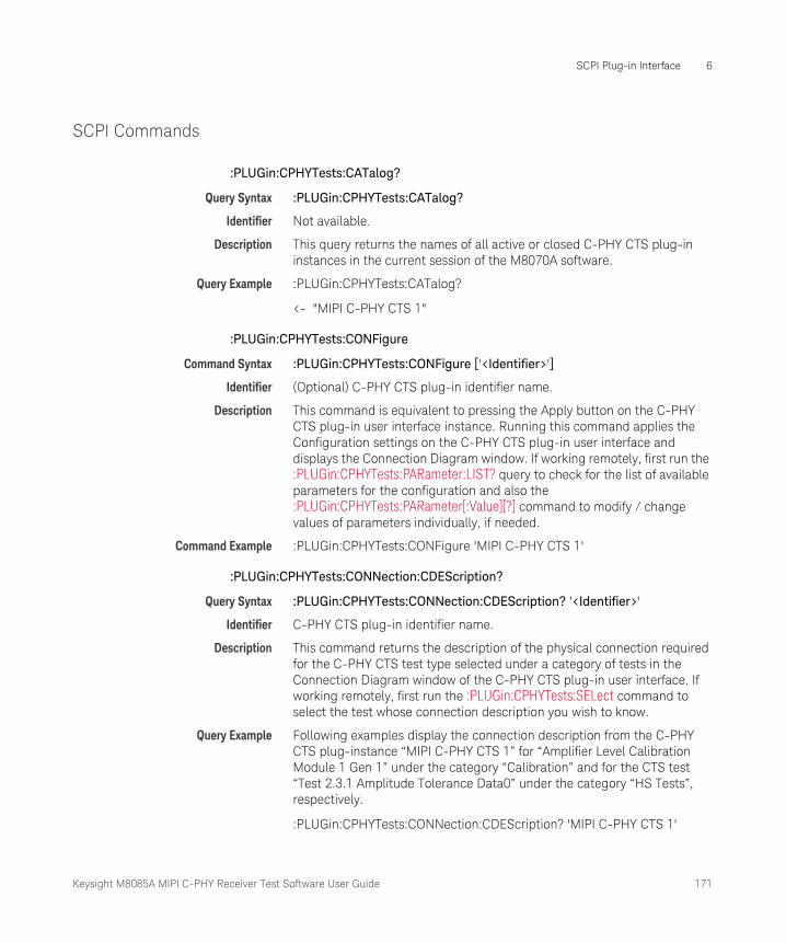
Keysight M8085A MIPI C-PHY Receiver Test Software User Guide 171
SCPI Plug-in Interface 6
SCPI Commands
:PLUGin:CPHYTests:CATalog?
Query Syntax :PLUGin:CPHYTests:CATalog?
Identifier Not available.
Description This query returns the names of all active or closed C-PHY CTS plug-in instances in the current session of the M8070A software.
Query Example :PLUGin:CPHYTests:CATalog?
<- "MIPI C-PHY CTS 1"
:PLUGin:CPHYTests:CONFigure
Command Syntax :PLUGin:CPHYTests:CONFigure ['<Identifier>']
Identifier (Optional) C-PHY CTS plug-in identifier name.
Description This command is equivalent to pressing the Apply button on the C-PHY CTS plug-in user interface instance. Running this command applies the Configuration settings on the C-PHY CTS plug-in user interface and displays the Connection Diagram window. If working remotely, first run the :PLUGin:CPHYTests:PARameter:LIST? query to check for the list of available parameters for the configuration and also the :PLUGin:CPHYTests:PARameter[:Value][?] command to modify / change values of parameters individually, if needed.
Command Example :PLUGin:CPHYTests:CONFigure 'MIPI C-PHY CTS 1'
:PLUGin:CPHYTests:CONNection:CDEScription?
Query Syntax :PLUGin:CPHYTests:CONNection:CDEScription? '<Identifier>'
Identifier C-PHY CTS plug-in identifier name.
Description This command returns the description of the physical connection required for the C-PHY CTS test type selected under a category of tests in the Connection Diagram window of the C-PHY CTS plug-in user interface. If working remotely, first run the :PLUGin:CPHYTests:SELect command to select the test whose connection description you wish to know.
Query Example Following examples display the connection description from the C-PHY CTS plug-instance “MIPI C-PHY CTS 1” for “Amplifier Level Calibration Module 1 Gen 1” under the category “Calibration” and for the CTS test “Test 2.3.1 Amplitude Tolerance Data0” under the category “HS Tests”, respectively.
:PLUGin:CPHYTests:CONNection:CDEScription? 'MIPI C-PHY CTS 1'
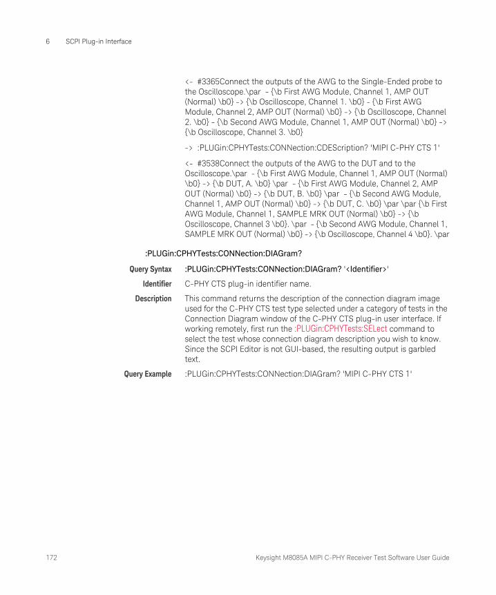
172 Keysight M8085A MIPI C-PHY Receiver Test Software User Guide
6 SCPI Plug-in Interface
<- #3365Connect the outputs of the AWG to the Single-Ended probe to the Oscilloscope.\par - {\b First AWG Module, Channel 1, AMP OUT (Normal) \b0} -> {\b Oscilloscope, Channel 1. \b0} - {\b First AWG Module, Channel 2, AMP OUT (Normal) \b0} -> {\b Oscilloscope, Channel 2. \b0} - {\b Second AWG Module, Channel 1, AMP OUT (Normal) \b0} -> {\b Oscilloscope, Channel 3. \b0}
-> :PLUGin:CPHYTests:CONNection:CDEScription? 'MIPI C-PHY CTS 1'
<- #3538Connect the outputs of the AWG to the DUT and to the Oscilloscope.\par - {\b First AWG Module, Channel 1, AMP OUT (Normal) \b0} -> {\b DUT, A. \b0} \par - {\b First AWG Module, Channel 2, AMP OUT (Normal) \b0} -> {\b DUT, B. \b0} \par - {\b Second AWG Module, Channel 1, AMP OUT (Normal) \b0} -> {\b DUT, C. \b0} \par \par {\b First AWG Module, Channel 1, SAMPLE MRK OUT (Normal) \b0} -> {\b Oscilloscope, Channel 3 \b0}. \par - {\b Second AWG Module, Channel 1, SAMPLE MRK OUT (Normal) \b0} -> {\b Oscilloscope, Channel 4 \b0}. \par
:PLUGin:CPHYTests:CONNection:DIAGram?
Query Syntax :PLUGin:CPHYTests:CONNection:DIAGram? '<Identifier>'
Identifier C-PHY CTS plug-in identifier name.
Description This command returns the description of the connection diagram image used for the C-PHY CTS test type selected under a category of tests in the Connection Diagram window of the C-PHY CTS plug-in user interface. If working remotely, first run the :PLUGin:CPHYTests:SELect command to select the test whose connection diagram description you wish to know. Since the SCPI Editor is not GUI-based, the resulting output is garbled text.
Query Example :PLUGin:CPHYTests:CONNection:DIAGram? 'MIPI C-PHY CTS 1'
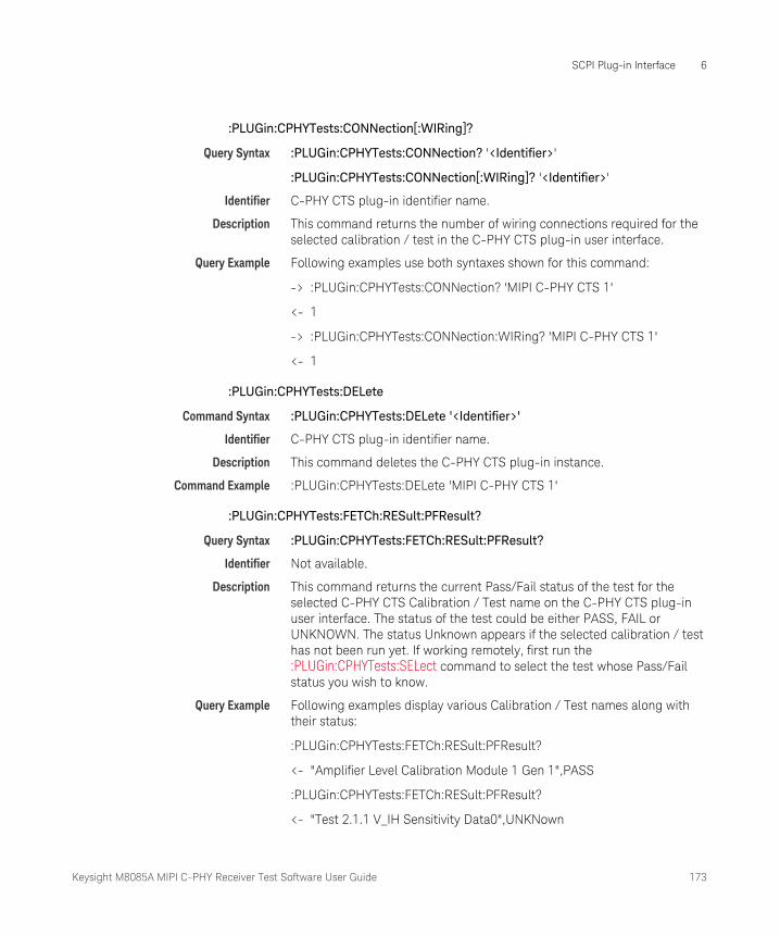
Keysight M8085A MIPI C-PHY Receiver Test Software User Guide 173
SCPI Plug-in Interface 6
:PLUGin:CPHYTests:CONNection[:WIRing]?
Query Syntax :PLUGin:CPHYTests:CONNection? '<Identifier>'
:PLUGin:CPHYTests:CONNection[:WIRing]? '<Identifier>'
Identifier C-PHY CTS plug-in identifier name.
Description This command returns the number of wiring connections required for the selected calibration / test in the C-PHY CTS plug-in user interface.
Query Example Following examples use both syntaxes shown for this command:
-> :PLUGin:CPHYTests:CONNection? 'MIPI C-PHY CTS 1'
<- 1
-> :PLUGin:CPHYTests:CONNection:WIRing? 'MIPI C-PHY CTS 1'
<- 1
:PLUGin:CPHYTests:DELete
Command Syntax :PLUGin:CPHYTests:DELete '<Identifier>'
Identifier C-PHY CTS plug-in identifier name.
Description This command deletes the C-PHY CTS plug-in instance.
Command Example :PLUGin:CPHYTests:DELete 'MIPI C-PHY CTS 1'
:PLUGin:CPHYTests:FETCh:RESult:PFResult?
Query Syntax :PLUGin:CPHYTests:FETCh:RESult:PFResult?
Identifier Not available.
Description This command returns the current Pass/Fail status of the test for the selected C-PHY CTS Calibration / Test name on the C-PHY CTS plug-in user interface. The status of the test could be either PASS, FAIL or UNKNOWN. The status Unknown appears if the selected calibration / test has not been run yet. If working remotely, first run the :PLUGin:CPHYTests:SELect command to select the test whose Pass/Fail status you wish to know.
Query Example Following examples display various Calibration / Test names along with their status:
:PLUGin:CPHYTests:FETCh:RESult:PFResult?
<- "Amplifier Level Calibration Module 1 Gen 1",PASS
:PLUGin:CPHYTests:FETCh:RESult:PFResult?
<- "Test 2.1.1 V_IH Sensitivity Data0",UNKNown

174 Keysight M8085A MIPI C-PHY Receiver Test Software User Guide
6 SCPI Plug-in Interface
:PLUGin:CPHYTests:FETCh:RESult[:VALue]?
Query Syntax :PLUGin:CPHYTests:FETCh:RESult? '<Identifier>'
:PLUGin:CPHYTests:FETCh:RESult:VALue? '<Identifier>'
Identifier The calibration / test name in the MIPI C-PHY CTS plug-in instance. Note that the # symbol is part of the syntax and is inserted as a separator.
Description This query returns all test parameters, the formatting of the table and the results for the selected C-PHY CTS Calibration / Test name in an XML format.
Query Example Following example displays the data associated with the Test 2.1.1 V_IH Sensitivity Clock test.
-> :PLUGin:CPHYTests:FETCh:RESult:VALue? 'MIPI C-PHY CTS 1#Test 2.1.1 V_IH Sensitivity Data0_1'
<- #41343<?xml version="1.0" encoding="utf-16"?><TestResults version="2.0"><TestResult><Summary><ProcedureName>Test 2.1.1 V_IH Sensitivity Data0</ProcedureName><ProcedureID>5100541</ProcedureID><Result>Passed</Result><DateTime>05/11/2017 15:50:40</DateTime><Duration>00:22:39.4014103</Duration><Description>This procedure test the LP Input High Voltage Sensitivity.</Description></Summary><ResultTables><ResultTable><Title>V_IH Tolerance_Data0</Title><Subtitle>Verify the V_IH tolerance</Subtitle><Name>V_IH Tolerance_Data0</Name><Parameters><Parameter name="Offline" value="True" /></Parameters><Columns><Column name="Result" unit="" recommendedExponent="0" width="13"><Value>pass</Value></Column><Column name="Min Passed V_IH" unit="V" precision="0" recommendedExponent="-3" width="8"><Value>0.6</Value></Column><Column name="Min Tested V_IH" unit="V" precision="0" recommendedExponent="-3" width="8"><Value>0.6</Value></Column><Column name="Min Spec V_IH" unit="V" precision="0" recommendedExponent="-3" width="8"><Value>0.74</Value></Column></Columns><cellColours><cellColour Name="64033NoColor" Value="16777215" /><cellColour Name="64037NoColor" Value="16777215" /><cellColour Name="64041NoColor" Value="16777215" /><cellColour Name="64042NoColor" Value="16777215" /></cellColours><Images /></ResultTable></ResultTables></TestResult></TestResults>

Keysight M8085A MIPI C-PHY Receiver Test Software User Guide 175
SCPI Plug-in Interface 6
:PLUGin:CPHYTests:HISTory:CATalog?
Query Syntax :PLUGin:CPHYTests:HISTory:CATalog?
Identifier Not available.
Description This query returns the names of all calibration / test results that have already been run in the C-PHY CTS plug-in instance.
Query Example -> :PLUGin:CPHYTests:HISTory:CATalog?
<- "Skew Calibration Module 1_1","Test 2.3.1 Amplitude Tolerance Data0_1"
:PLUGin:CPHYTests:LIST?
Query Syntax :PLUGin:CPHYTests:LIST?
Identifier Not available.
Description This query returns the names of all calibration / test procedures that appear in the Connection Diagram window for a certain Configuration setting in the C-PHY CTS plug-in instance. Note that this query returns a value only while the Connection Diagram window of the C-PHY CTS plug-in instance is active.
Query Example -> :PLUGin:CPHYTests:LIST?
<- "Amplifier Level Calibration Module 1 Gen 1","Amplifier Level Calibration Module 1 Gen 2","Amplifier Level Calibration Module 2 Gen 1","Skew Calibration Module 1","Inter Module Skew Calibration","LP Level Calibration High Data0 A","LP Level Calibration Low Data0 A","LP Level Calibration High Data0 B","LP Level Calibration Low Data0 B","LP Level Calibration High Data0 C","LP Level Calibration Low Data0 C","e-Spike Calibration Data0 A","HS Level Calibration Data0 A","HS Level Calibration Data0 B","HS Level Calibration Data0 C","TRTF Calibration 2500 MSps","ISI Calibration 2500 MSps","SJ Calibration 2500 MSps","DCD Calibration 2500 MSps","Eye Opening Calibration 2500 MSps","Test 2.3.1 Amplitude Tolerance Data0","Test 2.3.2 V_IDTH and V_IDTL Sensitivity Data0","Test 2.3.3 Jitter Tolerance Data0","Test 2.4.2 T_HS-Prepare - Data0 Procedure","Test 2.4.3 T_HS-PreBegin - Data0 Procedure","Test 2.4.4 T_HS-ProgSeq - Data0 Procedure","Test 2.4.5 T_HS-Post - Data0 Procedure","Test 2.4.1 Data0 Lane T_HS-TERM-EN","Test 2.1.1 V_IH Sensitivity Data0","Test 2.1.2 V_IL Sensitivity Data0","Test 2.1.3 V_HYST Sensitivity Data0 A Static","Test 2.1.3 V_HYST Sensitivity Data0 B Static","Test 2.1.3 V_HYST Sensitivity Data0 C Static","Test 2.1.3b V_HYST Sensitivity Data0 A Dynamic","Test 2.1.3b V_HYST Sensitivity Data0 B Dynamic","Test 2.1.3b V_HYST Sensitivity Data0 C Dynamic","Test 2.1.4 LP-RX Minimum Pulse Width ResponseData0","Test 2.1.5 LP-RX Input pos. Pulse Rejection e_spike Data0","Test 2.1.5 LP-RX Input neg. Pulse

176 Keysight M8085A MIPI C-PHY Receiver Test Software User Guide
6 SCPI Plug-in Interface
Rejection e_spike Data0","Test 2.2.1 Init. Period TINIT","Test 2.2.2 ULPS Exit TWAKEUP","Test 2.2.3 Invalid or Aborted Escape Entry","Test 2.2.4 Invalid or Aborted Escape Command","Test 2.2.5 Post-Trigger-Command","Test 2.2.6 Data Lane LP-RX Escape Mode Unsupported or Unassigned Commands"
:PLUGin:CPHYTests:NEW
Command Syntax :PLUGin:CPHYTests:NEW '<Identifier>'
Identifier C-PHY CTS plug-in identifier name.
Description This command creates a new C-PHY CTS plug-in interface. Run this command only when no other C-PHY CTS instance is active.
Command Example :PLUGin:CPHYTests:NEW 'MIPI C-PHY CTS 1'
:PLUGin:CPHYTests:PARameter:LIST?
Query Syntax :PLUGin:CPHYTests:PARameter:LIST? ['<Identifier>']
Identifier (Optional) The calibration / test name in the MIPI C-PHY CTS plug-in instance or just the MIPI C-PHY CTS plug-in instance name. Note that the # symbol is part of the syntax and is inserted as a separator.
Description This query returns the names and the currently assigned values for each parameter, listed on the Configuration window or those associated with the selected calibration / test procedures in the currently active C-PHY CTS plug-in instance. If working remotely, you may run the :PLUGin:CPHYTests:NEW command to create a new instance of the MIPI C-PHY CTS plug-in and view the parameter names and their default values. If you have already run the :PLUGin:CPHYTests:CONFigure command to switch to the Connection Diagram window, you may run the :PLUGin:CPHYTests:SELect command to select a calibration / test whose parameters you wish to view.
Query Example Following examples display the parameters associated with the “Test 2.3.1 Amplitude Tolerance Data0” (already selected in the user interface), “Test 2.3.3 Jitter Tolerance Data0” (specified in the query), and all parameters in the ‘MIPI C-PHY CTS 1’ plug-in instance, respectively, when they are selected.
-> :PLUGin:CPHYTests:PARameter:LIST?
<- ":TP1.System&Acquisition Parameters.PropertiesEditable","1",":TP1.System&Test 2.3.1 Amplitude Tolerance Data0.Offline","1",":TP1.System&Test 2.3.1 Amplitude Tolerance Data0.BER Reader init string","Data0_HS",":TP1.System&Test 2.3.1 Amplitude Tolerance Data0.BER Limit","1E-10",":TP1.System&Test 2.3.1 Amplitude Tolerance Data0.HS Symbol
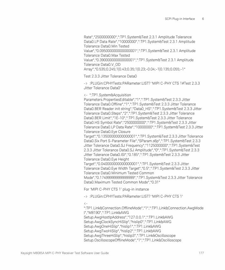
Keysight M8085A MIPI C-PHY Receiver Test Software User Guide 177
SCPI Plug-in Interface 6
Rate","2500000000",":TP1.System&Test 2.3.1 Amplitude Tolerance Data0.LP Data Rate","10000000",":TP1.System&Test 2.3.1 Amplitude Tolerance Data0.Min Tested Value","0.095000000000000001",":TP1.System&Test 2.3.1 Amplitude Tolerance Data0.Max Tested Value","0.39000000000000001",":TP1.System&Test 2.3.1 Amplitude Tolerance Data0.V_OD Array","0.535;0.245;1|0.43;0.35;1|0.23;-0.04;-1|0.135;0.055;-1"
Test 2.3.3 Jitter Tolerance Data0
-> :PLUGin:CPHYTests:PARameter:LIST? 'MIPI C-PHY CTS 1#Test 2.3.3 Jitter Tolerance Data0'
<- ":TP1.System&Acquisition Parameters.PropertiesEditable","1",":TP1.System&Test 2.3.3 Jitter Tolerance Data0.Offline","1",":TP1.System&Test 2.3.3 Jitter Tolerance Data0.BER Reader init string","Data0_HS",":TP1.System&Test 2.3.3 Jitter Tolerance Data0.Steps","2",":TP1.System&Test 2.3.3 Jitter Tolerance Data0.BER Limit","1E-10",":TP1.System&Test 2.3.3 Jitter Tolerance Data0.HS Symbol Rate","2500000000",":TP1.System&Test 2.3.3 Jitter Tolerance Data0.LP Data Rate","10000000",":TP1.System&Test 2.3.3 Jitter Tolerance Data0.Eye Closure Target","0.13500000000000001",":TP1.System&Test 2.3.3 Jitter Tolerance Data0.Six Port S-Parameter File","SParam.s6p",":TP1.System&Test 2.3.3 Jitter Tolerance Data0.SJ Frequency","1125000000",":TP1.System&Test 2.3.3 Jitter Tolerance Data0.SJ Amplitude","0",":TP1.System&Test 2.3.3 Jitter Tolerance Data0.ISI","0.185",":TP1.System&Test 2.3.3 Jitter Tolerance Data0.Eye Height Target","0.040000000000000001",":TP1.System&Test 2.3.3 Jitter Tolerance Data0.Eye Width Target","0.5",":TP1.System&Test 2.3.3 Jitter Tolerance Data0.Minimum Tested Common Mode","0.17499999999999999",":TP1.System&Test 2.3.3 Jitter Tolerance Data0.Maximum Tested Common Mode","0.31"
For ‘MIPI C-PHY CTS 1’ plug-in instance
-> :PLUGin:CPHYTests:PARameter:LIST? 'MIPI C-PHY CTS 1'
<- ":TP1.Link&Connection.OfflineMode","1",":TP1.Link&Connection.AwgModel","M8190",":TP1.Link&AWG Setup.AwgHostIpAddress","127.0.0.1",":TP1.Link&AWG Setup.AwgClockSyncHiSlip","hislip0",":TP1.Link&AWG Setup.AwgOneHiSlip","hislip1",":TP1.Link&AWG Setup.AwgTwoHiSlip","hislip2",":TP1.Link&AWG Setup.AwgThreeHiSlip","hislip3",":TP1.Link&Oscilloscope Setup.OscilloscopeOfflineMode","1",":TP1.Link&Oscilloscope

178 Keysight M8085A MIPI C-PHY Receiver Test Software User Guide
6 SCPI Plug-in Interface
Setup.OscilloscopeAddress","TCPIP0::121.0.0.1::inst0::INSTR",":TP1.System&Global.Spec Version","v1_00",":TP1.System&Global.Test Mode","COMpliance",":TP1.System&Global.NumberOfDataLanes","LANE1",":TP1.System&Global.Custom BER Reader Address","",":TP1.System&Global.MIPI BER Reader","OFFline",":TP1.System&Global.BER Limit","_1_10",":TP1.System&Global.HS Symbol Rate","2500000000",":TP1.System&Global.LP Data Rate","10000000",":TP1.System&Global.LP Transition Time","2.0000000000000001E-09",":TP1.System&Global.Manual Deskew","0",":TP1.System&Global.Triggered Start","0",":TP1.System&Global.HS Sequence Loop File","C:\ProgramData\BitifEye\Pattern\CPhy\HS.seq",":TP1.System&Global.LP Sequence Loop File","C:\ProgramData\BitifEye\Pattern\CPhy\CPhyCompliance.seq",":TP1.System&Global.Behavioral Sequence File","C:\ProgramData\BitifEye\Pattern\CPhy\CPhyBehavioral.seq",":TP1.System&Global.Re-Init Sequence before reset DUT","0",":TP1.System&Global.Re-Init Sequence after reset DUT","0",":TP1.System&Global.Mipi Protocol","DSI",":TP1.System&Levels.HS High Level","0.29999999999999999",":TP1.System&Levels.HS Mid Level","0.20000000000000001",":TP1.System&Levels.HS Low Level","0.10000000000000001",":TP1.System&Levels.LP High Level","1.2",":TP1.System&Levels.LP Low Level","0",":TP1.System&Timings.T3-PREPARE","9.9999999999999995E-08",":TP1.System&Timings.T3-PREBEGIN","3333333",":TP1.System&Timings.T3-PREEND","3333333",":TP1.System&Timings.T3-PROGSEQ","",":TP1.System&Timings.T3-SYNC","3444443",":TP1.System&Timings.T3-POST","4444444",":TP1.System&Timings.TX-HS-EXIT","1.9999999999999999E-07",":TP1.System&Timings.TX-WAKEUP","0.001",":TP1.System&Timings.TX-INIT","9.9999999999999995E-07",":TP1.System&Timings.SetDefault","",":TP1.System&Idle Voltage.Idle Voltage","0.29999999999999999"
:PLUGin:CPHYTests:PARameter[:Value][?]
Command Syntax :PLUGin:CPHYTests:PARameter '<Identifier>','<new value for the parameter>'
:PLUGin:CPHYTests:PARameter:Value '<Identifier>','<new value for the parameter>'
Query Syntax :PLUGin:CPHYTests:PARameter? '<Identifier>'
:PLUGin:CPHYTests:PARameter:Value? '<Identifier>'
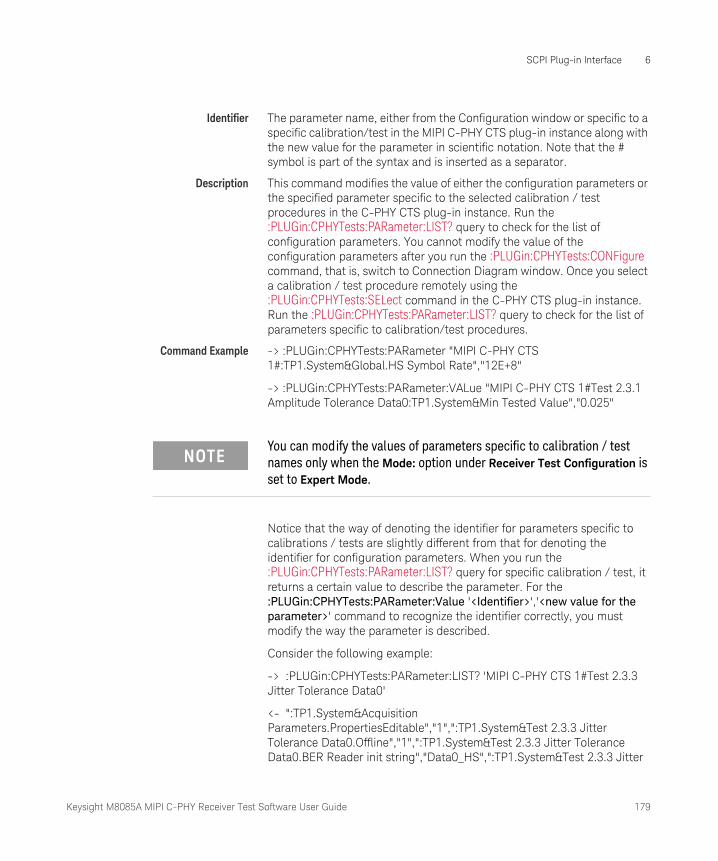
Keysight M8085A MIPI C-PHY Receiver Test Software User Guide 179
SCPI Plug-in Interface 6
Identifier The parameter name, either from the Configuration window or specific to a specific calibration/test in the MIPI C-PHY CTS plug-in instance along with the new value for the parameter in scientific notation. Note that the # symbol is part of the syntax and is inserted as a separator.
Description This command modifies the value of either the configuration parameters or the specified parameter specific to the selected calibration / test procedures in the C-PHY CTS plug-in instance. Run the :PLUGin:CPHYTests:PARameter:LIST? query to check for the list of configuration parameters. You cannot modify the value of the configuration parameters after you run the :PLUGin:CPHYTests:CONFigure command, that is, switch to Connection Diagram window. Once you select a calibration / test procedure remotely using the :PLUGin:CPHYTests:SELect command in the C-PHY CTS plug-in instance. Run the :PLUGin:CPHYTests:PARameter:LIST? query to check for the list of parameters specific to calibration/test procedures.
Command Example -> :PLUGin:CPHYTests:PARameter "MIPI C-PHY CTS 1#:TP1.System&Global.HS Symbol Rate","12E+8"
-> :PLUGin:CPHYTests:PARameter:VALue "MIPI C-PHY CTS 1#Test 2.3.1 Amplitude Tolerance Data0:TP1.System&Min Tested Value","0.025"
Notice that the way of denoting the identifier for parameters specific to calibrations / tests are slightly different from that for denoting the identifier for configuration parameters. When you run the :PLUGin:CPHYTests:PARameter:LIST? query for specific calibration / test, it returns a certain value to describe the parameter. For the :PLUGin:CPHYTests:PARameter:Value '<Identifier>','<new value for the parameter>' command to recognize the identifier correctly, you must modify the way the parameter is described.
Consider the following example:
-> :PLUGin:CPHYTests:PARameter:LIST? 'MIPI C-PHY CTS 1#Test 2.3.3 Jitter Tolerance Data0'
<- ":TP1.System&Acquisition Parameters.PropertiesEditable","1",":TP1.System&Test 2.3.3 Jitter Tolerance Data0.Offline","1",":TP1.System&Test 2.3.3 Jitter Tolerance Data0.BER Reader init string","Data0_HS",":TP1.System&Test 2.3.3 Jitter
NOTEYou can modify the values of parameters specific to calibration / test names only when the Mode: option under Receiver Test Configuration is set to Expert Mode.

180 Keysight M8085A MIPI C-PHY Receiver Test Software User Guide
6 SCPI Plug-in Interface
Tolerance Data0.Steps","2",":TP1.System&Test 2.3.3 Jitter Tolerance Data0.BER Limit","1E-10",":TP1.System&Test 2.3.3 Jitter Tolerance Data0.HS Symbol Rate","2500000000",":TP1.System&Test 2.3.3 Jitter Tolerance Data0.LP Data Rate","10000000",":TP1.System&Test 2.3.3 Jitter Tolerance Data0.Eye Closure Target","0.13500000000000001",":TP1.System&Test 2.3.3 Jitter Tolerance Data0.Six Port S-Parameter File","SParam.s6p",":TP1.System&Test 2.3.3 Jitter Tolerance Data0.SJ Frequency","1125000000",":TP1.System&Test 2.3.3 Jitter Tolerance Data0.SJ Amplitude","0",":TP1.System&Test 2.3.3 Jitter Tolerance Data0.ISI","0.185",":TP1.System&Test 2.3.3 Jitter Tolerance Data0.Eye Height Target","0.040000000000000001",":TP1.System&Test 2.3.3 Jitter Tolerance Data0.Eye Width Target","0.5",":TP1.System&Test 2.3.3 Jitter Tolerance Data0.Minimum Tested Common Mode","0.17499999999999999",":TP1.System&Test 2.3.3 Jitter Tolerance Data0.Maximum Tested Common Mode","0.31"
When you run the :PLUGin:CPHYTests:PARameter:LIST? query for Test 2.3.3 Jitter Tolerance Data0, it returns the parameters specific to that test along with their current values. If you wish to modify the value of the parameter ‘Eye Width Target’ (underlined above) remotely, you cannot simply use ":TP1.System&Test 2.3.3 Jitter Tolerance Data0.Eye Width Target" as the identifier for the :PLUGin:CPHYTests:PARameter:Value command. You must modify the text such that the identifier displays “current C-PHY plug-in instance name#Calibration/Test name:Functional Block&Parameter name”. So, for this example, the identifier becomes “MIPI C-PHY CTS 1#Test 2.3.3 Jitter Tolerance Data0:TP1.System&Eye Width Target”.
:PLUGin:CPHYTests:RESet
Command Syntax :PLUGin:CPHYTests:RESet '<Identifier>'
Identifier C-PHY CTS plug-in identifier name.
Description This command resets the settings of the C-PHY CTS plug-in instance to the default values.
Command Example :PLUGin:CPHYTests:RESet 'MIPI C-PHY CTS 1'
:PLUGin:CPHYTests:RUN:HISTory:CLEar
Command Syntax :PLUGin:CPHYTests:RUN:HISTory:CLEar
Identifier Not available.
Description This command clears the history information for any calibration / test runs from the “Measurement History” area in the C-PHY CTS plug-in instance.
Command Example :PLUGin:CPHYTests:RUN:HISTory:CLEar
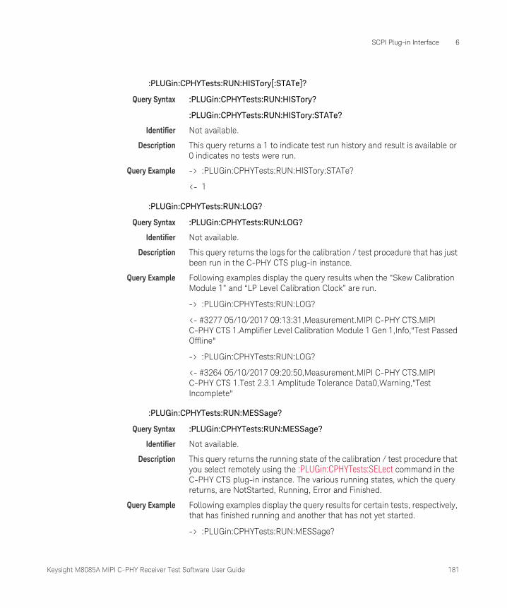
Keysight M8085A MIPI C-PHY Receiver Test Software User Guide 181
SCPI Plug-in Interface 6
:PLUGin:CPHYTests:RUN:HISTory[:STATe]?
Query Syntax :PLUGin:CPHYTests:RUN:HISTory?
:PLUGin:CPHYTests:RUN:HISTory:STATe?
Identifier Not available.
Description This query returns a 1 to indicate test run history and result is available or 0 indicates no tests were run.
Query Example -> :PLUGin:CPHYTests:RUN:HISTory:STATe?
<- 1
:PLUGin:CPHYTests:RUN:LOG?
Query Syntax :PLUGin:CPHYTests:RUN:LOG?
Identifier Not available.
Description This query returns the logs for the calibration / test procedure that has just been run in the C-PHY CTS plug-in instance.
Query Example Following examples display the query results when the “Skew Calibration Module 1” and “LP Level Calibration Clock” are run.
-> :PLUGin:CPHYTests:RUN:LOG?
<- #3277 05/10/2017 09:13:31,Measurement.MIPI C-PHY CTS.MIPI C-PHY CTS 1.Amplifier Level Calibration Module 1 Gen 1,Info,"Test Passed Offline"
-> :PLUGin:CPHYTests:RUN:LOG?
<- #3264 05/10/2017 09:20:50,Measurement.MIPI C-PHY CTS.MIPI C-PHY CTS 1.Test 2.3.1 Amplitude Tolerance Data0,Warning,"Test Incomplete"
:PLUGin:CPHYTests:RUN:MESSage?
Query Syntax :PLUGin:CPHYTests:RUN:MESSage?
Identifier Not available.
Description This query returns the running state of the calibration / test procedure that you select remotely using the :PLUGin:CPHYTests:SELect command in the C-PHY CTS plug-in instance. The various running states, which the query returns, are NotStarted, Running, Error and Finished.
Query Example Following examples display the query results for certain tests, respectively, that has finished running and another that has not yet started.
-> :PLUGin:CPHYTests:RUN:MESSage?
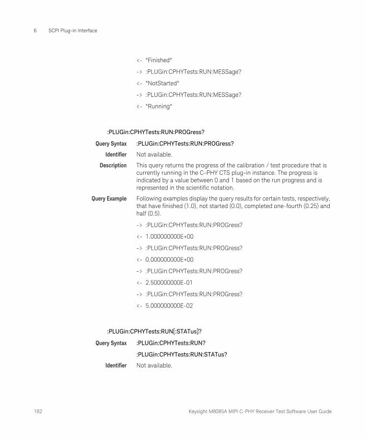
182 Keysight M8085A MIPI C-PHY Receiver Test Software User Guide
6 SCPI Plug-in Interface
<- "Finished"
-> :PLUGin:CPHYTests:RUN:MESSage?
<- "NotStarted"
-> :PLUGin:CPHYTests:RUN:MESSage?
<- "Running"
:PLUGin:CPHYTests:RUN:PROGress?
Query Syntax :PLUGin:CPHYTests:RUN:PROGress?
Identifier Not available.
Description This query returns the progress of the calibration / test procedure that is currently running in the C-PHY CTS plug-in instance. The progress is indicated by a value between 0 and 1 based on the run progress and is represented in the scientific notation.
Query Example Following examples display the query results for certain tests, respectively, that have finished (1.0), not started (0.0), completed one-fourth (0.25) and half (0.5).
-> :PLUGin:CPHYTests:RUN:PROGress?
<- 1.000000000E+00
-> :PLUGin:CPHYTests:RUN:PROGress?
<- 0.000000000E+00
-> :PLUGin:CPHYTests:RUN:PROGress?
<- 2.500000000E-01
-> :PLUGin:CPHYTests:RUN:PROGress?
<- 5.000000000E-02
:PLUGin:CPHYTests:RUN[:STATus]?
Query Syntax :PLUGin:CPHYTests:RUN?
:PLUGin:CPHYTests:RUN:STATus?
Identifier Not available.

Keysight M8085A MIPI C-PHY Receiver Test Software User Guide 183
SCPI Plug-in Interface 6
Description This query returns 1 or 0 to indicate whether a calibration / test you select remotely using the :PLUGin:CPHYTests:SELect command is in running state or not.
Query Example -> :PLUGin:CPHYTests:RUN:STATus?
<- 0
:PLUGin:CPHYTests:SELect
Command Syntax :PLUGin:CPHYTests:SELect '<Identifier>'
Identifier The calibration / test name in the MIPI C-PHY CTS plug-in instance. Note that the # symbol is part of the syntax and is inserted as a separator.
Description This command selects the specified Calibration / Test.
Command Example :PLUGin:CPHYTests:SELect 'MIPI C-PHY CTS 1#Test 2.1.2 V_IL Sensitivity Data0'
PLUGin:CPHYTests:STARt
Command Syntax :PLUGin:CPHYTests:STARt
Identifier Not available.
Description This command starts running the calibration / test error ratio measurement that you select remotely using the :PLUGin:CPHYTests:SELect command in the C-PHY CTS plug-in instance.
Command Example :PLUGin:CPHYTests:STARt
PLUGin:CPHYTests:STOP
Command Syntax :PLUGin:CPHYTests:STOP
Identifier Not available.
Description This command is used to forcefully abort the calibration / test error ratio measurement while it is still running.
Command Example :PLUGin:CPHYTests:STOP

184 Keysight M8085A MIPI C-PHY Receiver Test Software User Guide
6 SCPI Plug-in Interface

Keysight M8085A MIPI C-PHY Receiver Test Software
User Guide
7 IBerReader Interface
IBerReader Interface Definition / 187
IBerReader Usage / 190
Example Code Description / 193
Debugging / 195
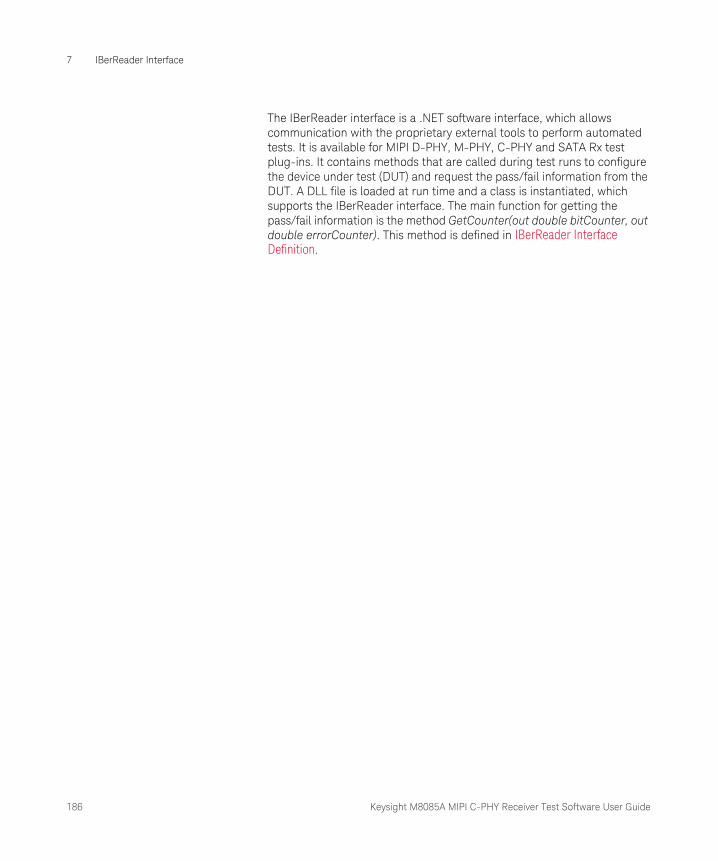
186 Keysight M8085A MIPI C-PHY Receiver Test Software User Guide
7 IBerReader Interface
The IBerReader interface is a .NET software interface, which allows communication with the proprietary external tools to perform automated tests. It is available for MIPI D-PHY, M-PHY, C-PHY and SATA Rx test plug-ins. It contains methods that are called during test runs to configure the device under test (DUT) and request the pass/fail information from the DUT. A DLL file is loaded at run time and a class is instantiated, which supports the IBerReader interface. The main function for getting the pass/fail information is the method GetCounter(out double bitCounter, out double errorCounter). This method is defined in IBerReader Interface Definition.
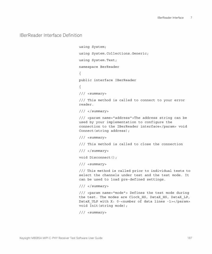
Keysight M8085A MIPI C-PHY Receiver Test Software User Guide 187
IBerReader Interface 7
IBerReader Interface Definition
using System;
using System.Collections.Generic;
using System.Text;
namespace BerReader
{
public interface IBerReader
{
/// <summary>
/// This method is called to connect to your error reader.
/// </summary>
/// <param name="address">The address string can be used by your implementation to configure the connection to the IBerReader interface</param> void Connect(string address);
/// <summary>
/// This method is called to close the connection
/// </summary>
void Disconnect();
/// <summary>
/// This method is called prior to individual tests to select the channels under test and the test mode. It can be used to load pre-defined settings.
/// </summary>
/// <param name="mode"> Defines the test mode during the test. The modes are Clock_HS, DataX_HS, DataX_LP, DataX_ULP with X: 0-<number of data lines -1></param> void Init(string mode);
/// <summary>
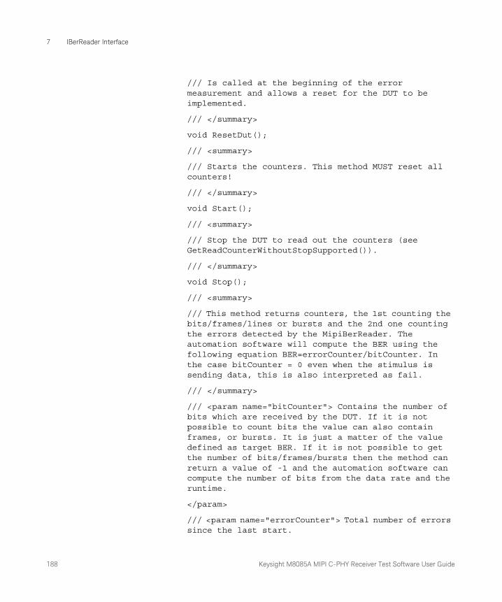
188 Keysight M8085A MIPI C-PHY Receiver Test Software User Guide
7 IBerReader Interface
/// Is called at the beginning of the error measurement and allows a reset for the DUT to be implemented.
/// </summary>
void ResetDut();
/// <summary>
/// Starts the counters. This method MUST reset all counters!
/// </summary>
void Start();
/// <summary>
/// Stop the DUT to read out the counters (see GetReadCounterWithoutStopSupported()).
/// </summary>
void Stop();
/// <summary>
/// This method returns counters, the 1st counting the bits/frames/lines or bursts and the 2nd one counting the errors detected by the MipiBerReader. The automation software will compute the BER using the following equation BER=errorCounter/bitCounter. In the case bitCounter = 0 even when the stimulus is sending data, this is also interpreted as fail.
/// </summary>
/// <param name="bitCounter"> Contains the number of bits which are received by the DUT. If it is not possible to count bits the value can also contain frames, or bursts. It is just a matter of the value defined as target BER. If it is not possible to get the number of bits/frames/bursts then the method can return a value of -1 and the automation software can compute the number of bits from the data rate and the runtime.
</param>
/// <param name="errorCounter"> Total number of errors since the last start.
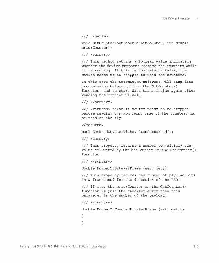
Keysight M8085A MIPI C-PHY Receiver Test Software User Guide 189
IBerReader Interface 7
/// </param>
void GetCounter(out double bitCounter, out double errorCounter);
/// <summary>
/// This method returns a Boolean value indicating whether the device supports reading the counters while it is running. If this method returns false, the device needs to be stopped to read the counters.
In this case the automation software will stop data transmission before calling the GetCounter() function, and re-start data transmission again after reading the counter values.
/// </summary>
/// <returns> false if device needs to be stopped before reading the counters, true if the counters can be read on the fly.
</returns>
bool GetReadCounterWithoutStopSupported();
/// <summary>
/// This property returns a number to multiply the value delivered by the bitCounter in the GetCounter() function.
/// </summary>
Double NumberOfBitsPerFrame {set; get;};
/// This property returns the number of payload bits in a frame used for the detection of the BER.
/// If i.e. the errorCounter in the GetCounter() function is just the checksum error then this parameter is the number of the payload.
/// </summary>
double NumberOfCountedBitsPerFrame {set; get;};
}
}

190 Keysight M8085A MIPI C-PHY Receiver Test Software User Guide
7 IBerReader Interface
IBerReader Usage
Each of the methods and properties of this interface are used during test execution. To understand the meaning and duty of the functionality, you must know the point in a test where these functions will be called. A helpful source for understanding the meaning are the comments added for each method in the IBerReader Interface Definition on page 187.
Integration
Copy your compiled version, which is a dll, into the default folder, the path for which is C:\Program Files\Keysight\M8070A\Plugins\Mipi\bin folder. Each application (MIPI CPhy, MIPI DPhy, MIPI MPhy, SATA) has a separate program files folder which is named like the application name. The IBerReader Interface Defintion is identified and loaded according to the name of the dll (MIPI C-Phy: CPhyCustomBerReader.dll, MIPI D-Phy: DPhyCustomBerReader.dll, MIPI M-Phy: MPhyCustomBerReader.dll, SATA: SataCustomBerReader.dll) from the sub folder Plugins\Mipi\bin of the C:\Program Files\Keysight\M8070A folder. If the custom BER reader implementation needs support from other helper DLL files other then the existing PlugIn DLLs, you must place such DLL files also in the same folder location or they must be made available via the PATH variable Windows.
If loaded successfully, a new entry in the BerReader list of the Configure DUT dialog is visible. After selection of the “Custom BER Reader”, the address field becomes editable, and the text of the address field is used as the argument for the Init (string address) method.
Connect/Disconnect
If the operator presses the Start button in the user interface, which is the start of the execution of the test list, the Connect(string address) is called, before the execution of the first test. If this fails with an exception, the test automation aborts the execution. The Init string is needed to check why the connect function did not work. Check the functionality by using the Test GUI with the same text in the address field. At the end of each run, the Disconnect() method is called. A run is the time between the press on the start button and the final completed dialog, which is shown at the end. In case that the repetition parameter is greater than zero, the Disconnect() method is called after the last repetition.

Keysight M8085A MIPI C-PHY Receiver Test Software User Guide 191
IBerReader Interface 7
Init
Init(string mode) is called once at the beginning of each test. The default parameters are set for the signaling and it is expected that the DUT can handle these default levels and timings at the RX side.
The content of the argument string “mode” is application dependent and needs to be requested from the application specific documentation. A more direct way to find out the exact string which is given as mode is to apply a break point in the Init method, and verify the setting for each test. In some applications like M-Phy, the argument of the mode string is available via the property grid and can even be modified for each test individually.
ResetDUT and GetCounter
ResetDut() is called just before each test point. It should be used to reset the bit and error counter and re-initialize the DUT to be ready for testing. A RX test procedure requires in the most cases several test points. For example, during a voltage sensitivity test several voltages are set and for each test point, a ResetDUT() is called. After the ResetDUT(), the test automation waits with the GetCounter(out double bitCounter, out double errorCounter) until the expected number of bits are transmitted. The number of bits depend on the target bit error rate and the confidence level that must be attained. As a simple calculation, the number of bits that must be compared is about three times of the target BER. Example target BER: 1e-10, Data Rate 1 GBit/s ? 3e10 bits are required ? 30 seconds test time is needed for each test point.
For a target BER below 1e-9, it may be suitable to request the bit and error counter before the theoretical integration time is reached to speed up the testing in case that errors are already visible. In this case, the test automation calls the GetCounter() method several times for each test point. It is expected that the bit and the error counters will not be reseted by these calls.
Configuration and Conditions
GetReadCounterWithoutStopSupported() is called before each test point. If the return value is true, then no Stop() or Start() methods are called. For some implementation, it is necessary to stop the execution of the bit comparison (see LogicAnalyserBerReader), before it is possible to read out the counter.
NumberOfBitsPerFrame and NumberOfCountedBitsPerFrame is used to compute the test time and BER. By these properties, it is possible to give a frame counter instead of a bit counter in the GetCounter() function. The

192 Keysight M8085A MIPI C-PHY Receiver Test Software User Guide
7 IBerReader Interface
BER is calculated in this case by multiplying the bit counter with the NumberOfCountedBitsPerFrame. In applications where the data stream contains blanking periods, or bits which are not be taken into account for the bit comparison, the NumberOfBitsPerFrame and NumberOfCountedBitsPerFrame will be different, and the test time is extended. The values for these parameters depend on the pattern which is used for testing. For some applications the test pattern is well defined, but the test automation allows to use another one. In this case the IBerReader should provide suitable values for these parameters.
Keysight M8085A MIPI C-PHY Receiver Test Software User Guide 193
IBerReader Interface 7
Example Code Description
The SDK for implementing the IBerReader interface comes with several example Visual Studio Projects and a project containing a test user interface, to test the implementation beforehand. The projects are:
• IBerReaderTestGui: project for building the IBerReader Test GUI. Via this GUI the functionality of the own implementation can be tested.
• LogicAnalyserBerReader: implementation using a logic analyzer as configuration tool and error detector.
• MipiCustomBerReader: example code with empty method implementations, which can be used as start for the own implementation.
• OfflineBerReader: example code for an offline BER reader. Instead of a direct access to a tool that configures the DUT, dialogs are shown to let the user do the configuration, and finally ask, if the DUT is working properly.
IBerReader Test GUI
The Test GUI allows to test the own implementation of a CustomBerReader. The GUI allows you to execute all methods of the IBerReader implementation. Since the source code is available, debugging can be done via this user interface.
MipiCustomBerReader
The MIPICustomBerReader project contains an empty CustomBerReader class. All necessary methods and properties are available but just contains a throw new Exception (“Not implemented.”) call. This project can be used as a template for implementation.
194 Keysight M8085A MIPI C-PHY Receiver Test Software User Guide
7 IBerReader Interface
OfflineBerReader
The OfflineBerReader project contains the implementation of an “offline” version of a IBerReader supporting class. All methods show a dialog to the operator instead of calling the DUT or tools directly. It can be used to see when and how the IBerReader methods are used inside of the test automation.
LogicAnalyserBerReader
The LogicAnalyserBerReader IBerReader implementation enables controlling of the Logic Analyser (LA). In this application, the LA configures the device via the pattern generator modules, and the analyser modules are connected to the parallel interface of the DUT. Via this parallel interface, the same data which are received via the high speed C-PHY interface are sampled, and via a special trigger setup the pattern is compared. The counter of the trigger are used for gaining the number of received bursts, and the number of errors. The configuration of the DUT is done by loading and executing a LA pattern generator setup file, and the setup for the analyser contains the necessary port assignment for the PPI. To create a suitable setup for the actual DUT is under your control.
Keysight M8085A MIPI C-PHY Receiver Test Software User Guide 195
IBerReader Interface 7
Debugging
Debugging using the Test GUI
The easiest way for debugging is using the Test GUI. The source code is available and therefore, it is possible to set break points in each method which is using the IBerReader functionality. If the developer puts the project of the IBerReader implementation in the same Visual Studio solution, it follows the source lines of the IBerReader class in case of stepwise running the debugger (Keys F10, step over, and F11, step into). To get a reasonable signal at the inputs of the DUT the test automation, a frame generator, or any other signal source, which can generate signals, conforming to the specification, can be used. If the test automation is used, either the offline BER reader can be used to stop the execution of the test at each IBerReader call, or the compiled DLL. If the compiled DLL is used, it makes more sense to use the test automation as startup application for debug than the Test GUI. Using the frame generator as controller for the signal sources is the most flexible way, because by the frame generator all parameters can be set in the optimum range to test the error free behavior of the DUT, and setting one parameter at the edge of the DUT capability, the error counter functionality can be tested.

196 Keysight M8085A MIPI C-PHY Receiver Test Software User Guide
7 IBerReader Interface

Keysight M8085A MIPI C-PHY Receiver Test Software User Guide 197

This information is subject to change without notice.© Keysight Technologies 2017Edition 3.0, June 2017
www.keysight.com