keysight n5990a test automation software platform - … test automation... · data sheet keysight...
TRANSCRIPT
Data Sheet
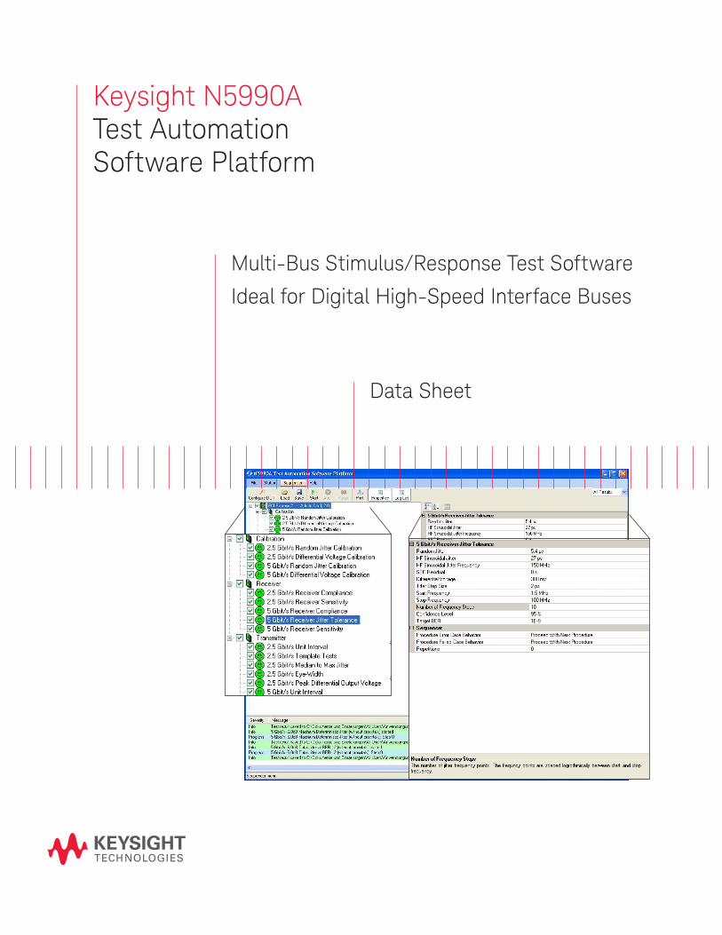
Keysight N5990ATest Automation Software Platform
Multi-Bus Stimulus/Response Test Software
Ideal for Digital High-Speed Interface Buses
– Universal bus test solution, sup-
ports MIPI D-PHY, MIPI M-PHY,
HDMI, MHL, DisplayPort, PCI
Express®, SATA and USB, other
standards are under develop-
ment
– Single and multi-lane device
testing
– Complements and enhances
Infiniium oscilloscope bus test
software applications
– Fast system calibration
– One button compliance tests
– Characterization mode for in-
depth testing
– Supports real-time parameter
changes of amplitude levels etc.
– Microsoft Excel reports for easy
post-processing
– Optional interfaces to web and
database servers
– Optional user programming for
legacy code integration (e.g.
LabView, VEE, C++) and custom
test procedures
– Complementary services
Overview
– N5990A takes test automation to the next level of performance and convenience
Turn your test instruments into a solution
An efficient test strategy is a proven com-
petitive advantage. Keysight Technologies’
N5990A test automation software
platform is a key element of winning
strategies.
By combining the performance of your
instruments with the convenience of your
PC, the N5990A provides unprecedented
test integration, high throughput and ease-
of-use for a wide range of stimulus and
response systems. It is this level of control
that turns a collection of instruments into a
generic test solution.
Fast and reliable testing
The comprehensive N5990A software
platform increases testing speed, reduces
test costs and ensures greater thorough-
ness than manual electrical testing. Using
PCI Express as an example, it is suitable
for testing devices such as transmitters,
receivers and bridges, network adapters,
DSP, TV and data acquisition cards,
whether you are evaluating production
ready prototypes or development boards
or chipsets.
Proven reference solution
The N5990A has proven its compliance
testing abilities at many interoper-
ability workshops (“plug fests”) since its
introduction in January 2006. As a result,
N5990A is recommended e.g. in the
HDMI CTS and the SATA RSG MOI. From
the beginning, N5990A delivered what
competitive products are just starting to
explore.
Receiver tests
The N5990A’s receiver test options pro-
vide dedicated receiver and sink compli-
ance tests for popular and emerging digital
buses. The libraries ideally complement
Keysight’s portfolio of transmitter and
source test software applications for com-
puter buses such as PCI Express (N5393C)
or video buses like HDMI (N5399B). Apart
from the fast reassurance of the compli-
ance mode, the characterization mode
offers in-depth analysis.
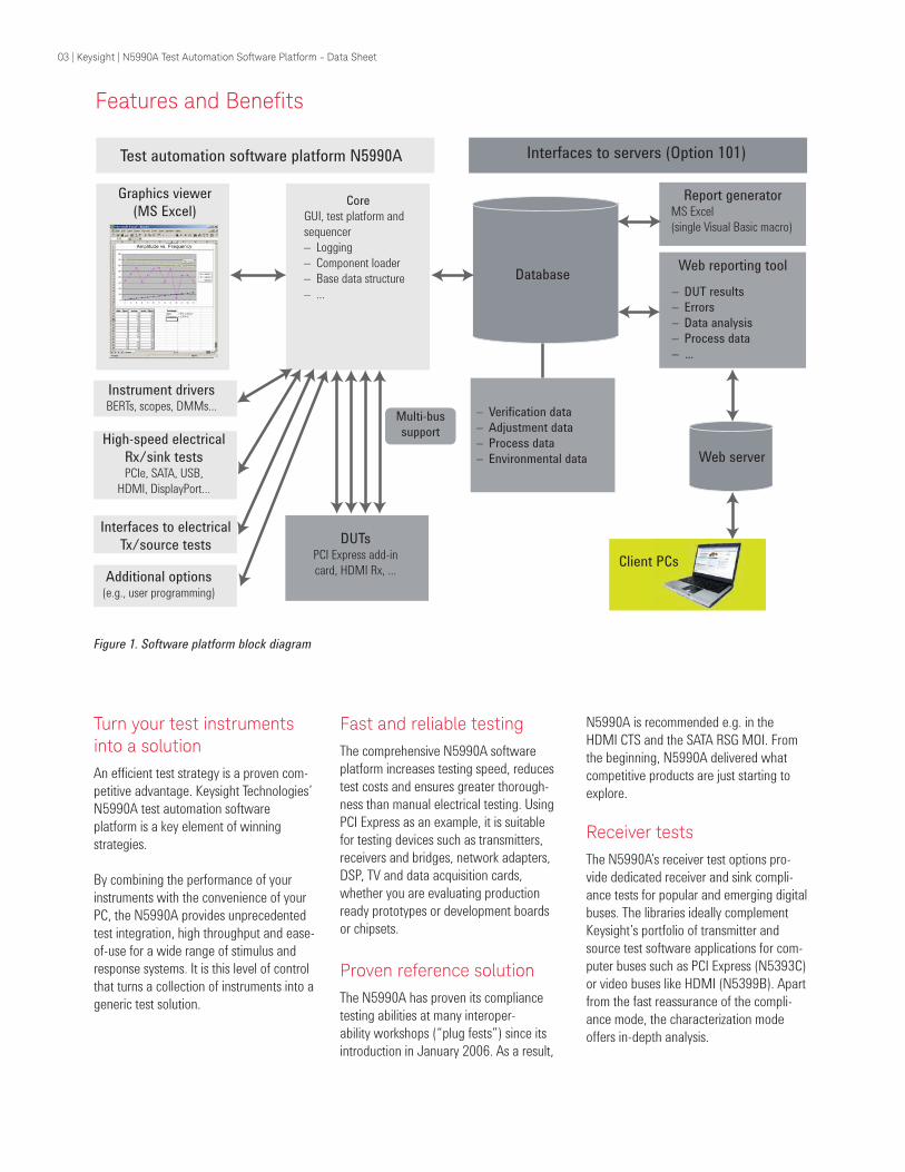
Figure 1. Software platform block diagram
Features and Beneits
Graphics viewer
(MS Excel)
Instrument driversBERTs, scopes, DMMs...
Test automation software platform N5990A Interfaces to servers (Option 101)
Core
GUI, test platform and
sequencer
– Logging
– Component loader
– Base data structure
– ...
High-speed electrical
Rx/sink testsPCIe, SATA, USB,
HDMI, DisplayPort...
Additional options(e.g., user programming)
DUTsPCI Express add-in
card, HDMI Rx, ...
Multi-bus
support
Database
Web server
Web reporting tool
– DUT results
– Errors
– Data analysis
– Process data
– ...
Report generatorMS Excel
(single Visual Basic macro)
– Verification data
– Adjustment data
– Process data
– Environmental data
Interfaces to electrical
Tx/source testsClient PCs
03 | Keysight | N5990A Test Automation Software Platform - Data Sheet
Integrated, generic solution
The N5990A supports a broad portfolio
of Keysight instruments, such as serial
bit error ratio testers (BERTs), the multi-
channel ParBERT platform, and Infiniium
oscilloscopes (see Figure 2). It also allows
efficient control of jitter sources like func-
tion, arbitrary waveform or high-quality
signal generators.
You can select the hardware performance
you need to test your specific DUT, single
or multi-lane. The N5990A’s software lay-
ers seamlessly complement the instrument
software, providing a common, generic
test environment.
Standardize your tests
The automation platform makes it simple
to test multiple buses. The same user
interface applies to buses as different as
HDMI, PCI Express or MIPI Express. This
translates to significant productivity gains.
More time is gained by the common Excel
format for reporting results (see Figure 3),
and common data structures for advanced
data management using data bases.
Features and Beneits
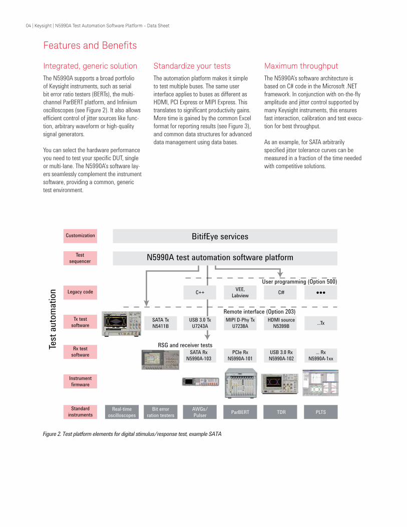
Figure 2. Test platform elements for digital stimulus/response test, example SATA
Customization
Test
sequencer
Legacy code
Tx test
software
Rx test
software
Instrument
firmware
Standard
instruments
Test
auto
mati
on
BitifEye services
N5990A test automation software platform
C++VEE,
LabviewC# ●●●
SATA Tx
N5411B
USB 3.0 Tx
U7243A
MIPI D-Phy Tx
U7238A
HDMI source
N5399B...Tx
SATA Rx
N5990A-103
PCIe Rx
N5990A-101
USB 3.0 Rx
N5990A-102
... Rx
N5990A-1xx
RSG and receiver tests
Real-time
oscilloscopes
Bit error
ration testers
AWGs/
PulserParBERT TDR PLTS
User programming (Option 500)
Remote interface (Option 203)
Maximum throughput
The N5990A’s software architecture is
based on C# code in the Microsoft .NET
framework. In conjunction with on-the-fly
amplitude and jitter control supported by
many Keysight instruments, this ensures
fast interaction, calibration and test execu-
tion for best throughput.
As an example, for SATA arbitrarily
specified jitter tolerance curves can be
measured in a fraction of the time needed
with competitive solutions.
04 | Keysight | N5990A Test Automation Software Platform - Data Sheet
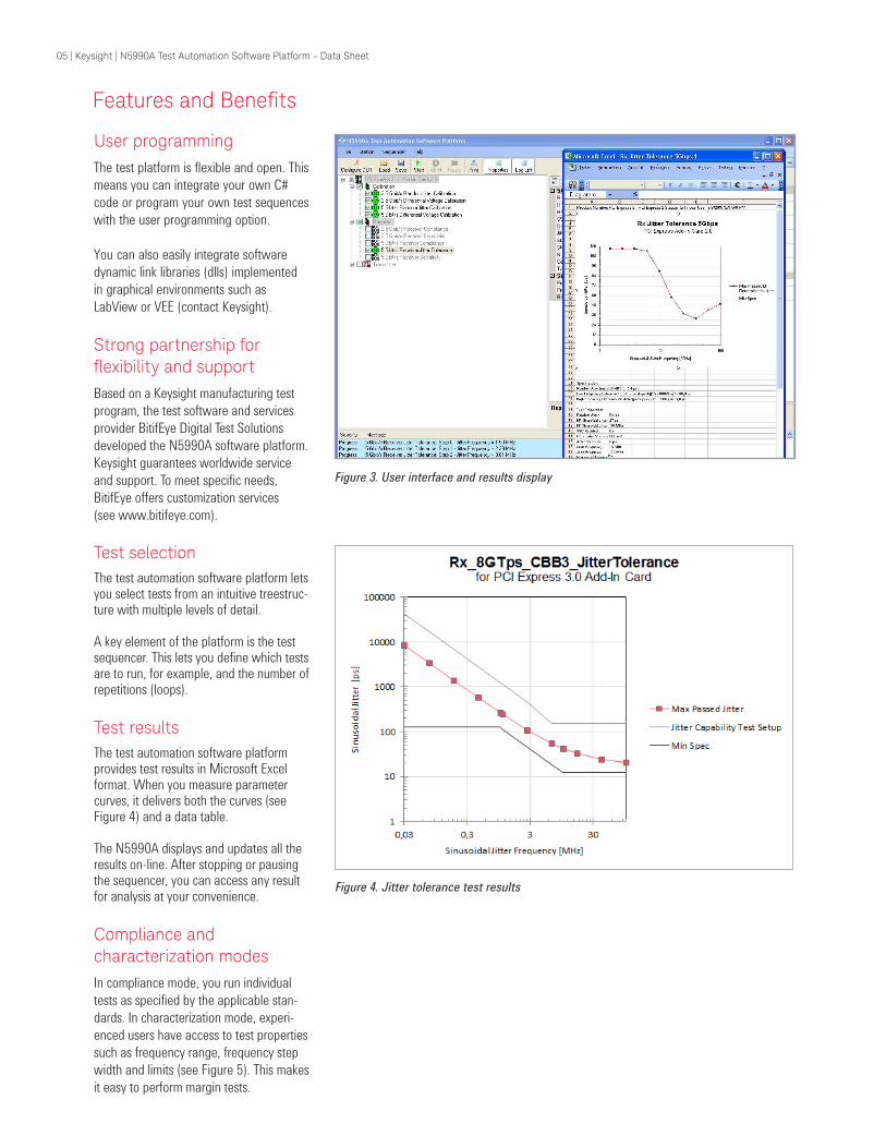
User programming
The test platform is flexible and open. This
means you can integrate your own C#
code or program your own test sequences
with the user programming option.
You can also easily integrate software
dynamic link libraries (dlls) implemented
in graphical environments such as
LabView or VEE (contact Keysight).
Strong partnership for lexibility and support Based on a Keysight manufacturing test
program, the test software and services
provider BitifEye Digital Test Solutions
developed the N5990A software platform.
Keysight guarantees worldwide service
and support. To meet specific needs,
BitifEye offers customization services
(see www.bitifeye.com).
Figure 3. User interface and results display
Features and Beneits
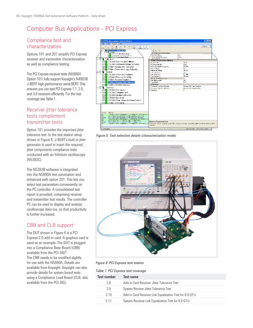
Figure 4. Jitter tolerance test results
Test selection
The test automation software platform lets you select tests from an intuitive treestruc-ture with multiple levels of detail.
A key element of the platform is the test sequencer. This lets you define which tests are to run, for example, and the number of repetitions (loops).
Test results
The test automation software platform provides test results in Microsoft Excel format. When you measure parameter curves, it delivers both the curves (see Figure 4) and a data table.
The N5990A displays and updates all the results on-line. After stopping or pausing the sequencer, you can access any result for analysis at your convenience.
Compliance and characterization modes
In compliance mode, you run individual
tests as specified by the applicable stan-
dards. In characterization mode, experi-
enced users have access to test properties
such as frequency range, frequency step
width and limits (see Figure 5). This makes
it easy to perform margin tests.
05 | Keysight | N5990A Test Automation Software Platform - Data Sheet
Compliance test and characterization
Options 101 and 201 simplify PCI Express
receiver and transmitter characterization
as well as compliance testing.
The PCI Express receiver tests (N5990A
Option 101) fully support Keysight’s N4903B
J-BERT high-performance serial BERT. This
ensures you can test PCI Express 1.1, 2.0,
and 3.0 receivers efficiently. For the test
coverage see Table 1.
Receiver jitter tolerance tests complement transmitter tests
Option 101 provides the important jitter
tolerance test. In the test station setup
shown in Figure 6, J-BERT’s built-in jitter
generator is used to insert the required
jitter components compliance tests
conducted with an Infiniium oscilloscope
(N5393C).
The N5393B software is integrated
into the N5990A test automation and
enhanced with option 201. This lets you
select test parameters conveniently on
the PC controller. A consolidated test
report is provided, comprising receiver
and transmitter test results. The controller
PC can be used to display and analyse
oscilloscope data too, so that productivity
is further increased.
CBB and CLB support
The DUT shown in Figure 6 is a PCI
Express 2.0 add-in card. A graphics card is
used as an example. The DUT is plugged
into a Compliance Base Board (CBB)
available from the PCI-SIG®.
The CBB needs to be modified slightly
for use with the N5990A. Details are
available from Keysight. Keysight can also
provide details for system board tests
using a Compliance Load Board (CLB, also
available from the PCI-SIG).
Computer Bus Applications - PCI Express
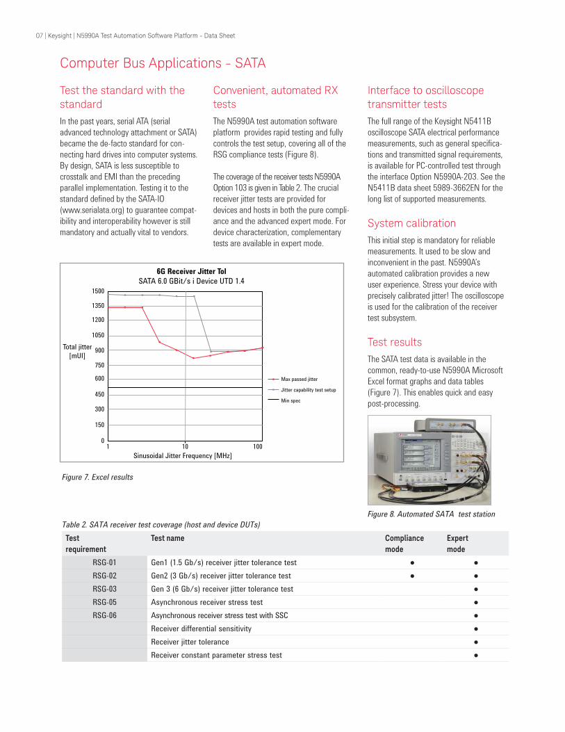
Figure 5. Test selection details (characterization mode)
Figure 6: PCI Express test station
Table 1. PCI Express test coverage
Test number Test name
2.8 Add-in Card Receiver Jitter Tolerance Test
2.9 System Receive Jitter Tolerance Test
2.10 Add-in Card Receiver Link Equalization Test for 8.0 GT/s
2.11 System Receiver Link Equalization Test for 8.0 GT/s
06 | Keysight | N5990A Test Automation Software Platform - Data Sheet
Computer Bus Applications - SATA
Test the standard with the standard
In the past years, serial ATA (serial
advanced technology attachment or SATA)
became the de-facto standard for con-
necting hard drives into computer systems.
By design, SATA is less susceptible to
crosstalk and EMI than the preceding
parallel implementation. Testing it to the
standard defined by the SATA-IO
(www.serialata.org) to guarantee compat-
ibility and interoperability however is still
mandatory and actually vital to vendors.
Convenient, automated RX tests
The N5990A test automation software
platform provides rapid testing and fully
controls the test setup, covering all of the
RSG compliance tests (Figure 8).
The coverage of the receiver tests N5990A
Option 103 is given in Table 2. The crucial
receiver jitter tests are provided for
devices and hosts in both the pure compli-
ance and the advanced expert mode. For
device characterization, complementary
tests are available in expert mode.
Figure 8. Automated SATA test station
1500
1350
1200
1050
900
750
600
450
300
150
01 10 100
Sinusoidal Jitter Frequency [MHz]
Total jitter
[mUI]
Max passed jitter
Jitter capability test setup
Min spec
6G Receiver Jitter Tol
SATA 6.0 GBit/s i Device UTD 1.4
Figure 7. Excel results
Table 2. SATA receiver test coverage (host and device DUTs)
Test
requirement
Test name Compliance
mode
Expert
mode
RSG-0 1 Gen1 (1 .5 Gb/s) receiver jitter tolerance test ● ●
RSG-0 2 Gen2 (3 Gb/s) receiver jitter tolerance test ● ●
RSG-0 3 Gen 3 (6 Gb/s) receiver jitter tolerance test ●
RSG-0 5 Asynchronous receiver stress test ●
RSG-0 6 Asynchronous receiver stress test with SSC ●
Receiver differential sensitivity ●
Receiver jitter tolerance ●
Receiver constant parameter stress test ●
Interface to oscilloscope transmitter tests
The full range of the Keysight N5411B
oscilloscope SATA electrical performance
measurements, such as general specifica-
tions and transmitted signal requirements,
is available for PC-controlled test through
the interface Option N5990A-203. See the
N5411B data sheet 5989-3662EN for the
long list of supported measurements.
System calibration
This initial step is mandatory for reliable
measurements. It used to be slow and
inconvenient in the past. N5990A’s
automated calibration provides a new
user experience. Stress your device with
precisely calibrated jitter! The oscilloscope
is used for the calibration of the receiver
test subsystem.
Test results
The SATA test data is available in the
common, ready-to-use N5990A Microsoft
Excel format graphs and data tables
(Figure 7). This enables quick and easy
post-processing.
07 | Keysight | N5990A Test Automation Software Platform - Data Sheet
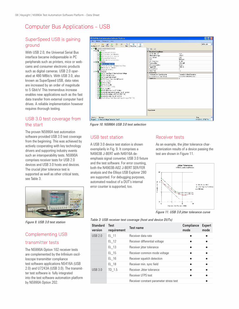
USB test station
A USB 3.0 device test station is shown
exemplarily in Fig. 9. It comprises a
N4903B J-BERT with N4916A de-
emphasis signal converter, USB 3.0 fixture
and the test software. For error counting,
both the N4903B-A02 J-BERT SER/FER
analysis and the Ellisys USB Explorer 280
are supported. For debugging purposes,
automated readout of a DUT’s internal
error counter is supported, too.
SuperSpeed USB is gaining ground
With USB 2.0, the Universal Serial Bus
interface became indispensable in PC
peripherals such as printers, mice or web-
cams and consumer electronic products
such as digital cameras. USB 2.0 oper-
ated at 480 MBit/s. With USB 3.0, also
known as SuperSpeed USB, data rates
are increased by an order of magnitude
to 5 Gbit/s! This tremendous increase
enables new applications such as the fast
data transfer from external computer hard
drives. A reliable implementation however
requires thorough testing.
USB 3.0 test coverage from the start
The proven N5990A test automation
software provided USB 3.0 test coverage
from the beginning. This was achieved by
actively cooperating with key technology
drivers and supporting industry events
such an interoperability tests. N5990A
comprises receiver tests for USB 2.0
devices and USB 3.0 hosts and devices.
The crucial jitter tolerance test is
supported as well as other critical tests,
see Table 3.
Computer Bus Applications - USB
Figure 10. N5990A USB 3.0 test selection
Receiver tests
As an example, the jitter tolerance char-
acterization results of a device passing the
test are shown in Figure 11.
Figure 9. USB 3.0 test station
Figure 11. USB 3.0 jitter tolerance curve
Table 3: USB receiver test coverage (host and device DUTs)
Standard
version
Test
requirementTest name
Compliance
mode
Expert
mode
USB 2.0 EL_11 Receiver data rate ● ●
EL_12 Receiver differential voltage ● ●
EL_13 Receiver jitter tolerance ● ●
EL_15 Receiver common mode voltage ● ●
EL_16 Receiver squelch detection ● ●
EL_18 Receiver min. sync field ● ●
USB 3.0 TD_1.5 Receiver Jitter tolerance ● ●
Receiver LFPS test ● ●
Receiver constant parameter stress test ●
Complementing USB
transmitter tests
The N5990A Option 102 receiver tests
are complemented by the Infiniium oscil-
loscope transmitter compliance
test software applications N5416A (USB
2.0) and U7243A (USB 3.0). The transmit-
ter test software is fully integrated
into the test software automation platform
by N5990A Option 202.
08 | Keysight | N5990A Test Automation Software Platform - Data Sheet
Consumer Electronics and Video Test Applications - HDMI
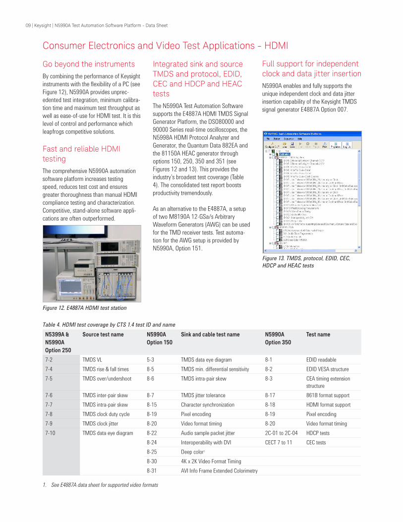
Go beyond the instruments
By combining the performance of Keysight
instruments with the flexibility of a PC (see
Figure 12), N5990A provides unprec-
edented test integration, minimum calibra-
tion time and maximum test throughput as
well as ease-of-use for HDMI test. It is this
level of control and performance which
leapfrogs competitive solutions.
Fast and reliable HDMI testing
The comprehensive N5990A automation
software platform increases testing
speed, reduces test cost and ensures
greater thoroughness than manual HDMI
compliance testing and characterization.
Competitive, stand-alone software appli-
cations are often outperformed.
Integrated sink and source TMDS and protocol, EDID, CEC and HDCP and HEAC tests
The N5990A Test Automation Software
supports the E4887A HDMI TMDS Signal
Generator Platform, the DSO80000 and
90000 Series real-time oscilloscopes, the
N5998A HDMI Protocol Analyzer and
Generator, the Quantum Data 882EA and
the 81150A HEAC generator through
options 150, 250, 350 and 351 (see
Figures 12 and 13). This provides the
industry’s broadest test coverage (Table
4). The consolidated test report boosts
productivity tremendously.
As an alternative to the E4887A, a setup
of two M8190A 12-GSa/s Arbitrary
Waveform Generators (AWG) can be used
for the TMD receiver tests. Test automa-
tion for the AWG setup is provided by
N5990A, Option 151.
Table 4. HDMI test coverage by CTS 1.4 test ID and name
N5399A &
N5990A
Option 250
Source test name N5990A
Option 150
Sink and cable test name N5990A
Option 350
Test name
7-2 TMDS VL 5-3 TMDS data eye diagram 8-1 EDID readable
7-4 TMDS rise & fall times 8-5 TMDS min. differential sensitivity 8-2 EDID VESA structure
7-5 TMDS over/undershoot 8-6 TMDS intra-pair skew 8-3 CEA timing extension
structure
7-6 TMDS inter-pair skew 8-7 TMDS jitter tolerance 8-17 861B format support
7-7 TMDS intra-pair skew 8-15 Character synchronization 8-18 HDMI format support
7-8 TMDS clock duty cycle 8-19 Pixel encoding 8-19 Pixel encoding
7-9 TMDS clock jitter 8-20 Video format timing 8-20 Video format timing
7-10 TMDS data eye diagram 8-22 Audio sample packet jitter 2C-01 to 2C-04 HDCP tests
8-24 Interoperability with DVI CECT 7 to 11 CEC tests
8-25 Deep color1
8-30 4K x 2K Video Format Timing
8-31 AVI Info Frame Extended Colorimetry
1. See E4887A data sheet for supported video formats
Figure 12. E4887A HDMI test station
Figure 13. TMDS, protocol, EDID, CEC,
HDCP and HEAC tests
Full support for independent clock and data jitter insertion
N5990A enables and fully supports the
unique independent clock and data jitter
insertion capability of the Keysight TMDS
signal generator E4887A Option 007.
09 | Keysight | N5990A Test Automation Software Platform - Data Sheet
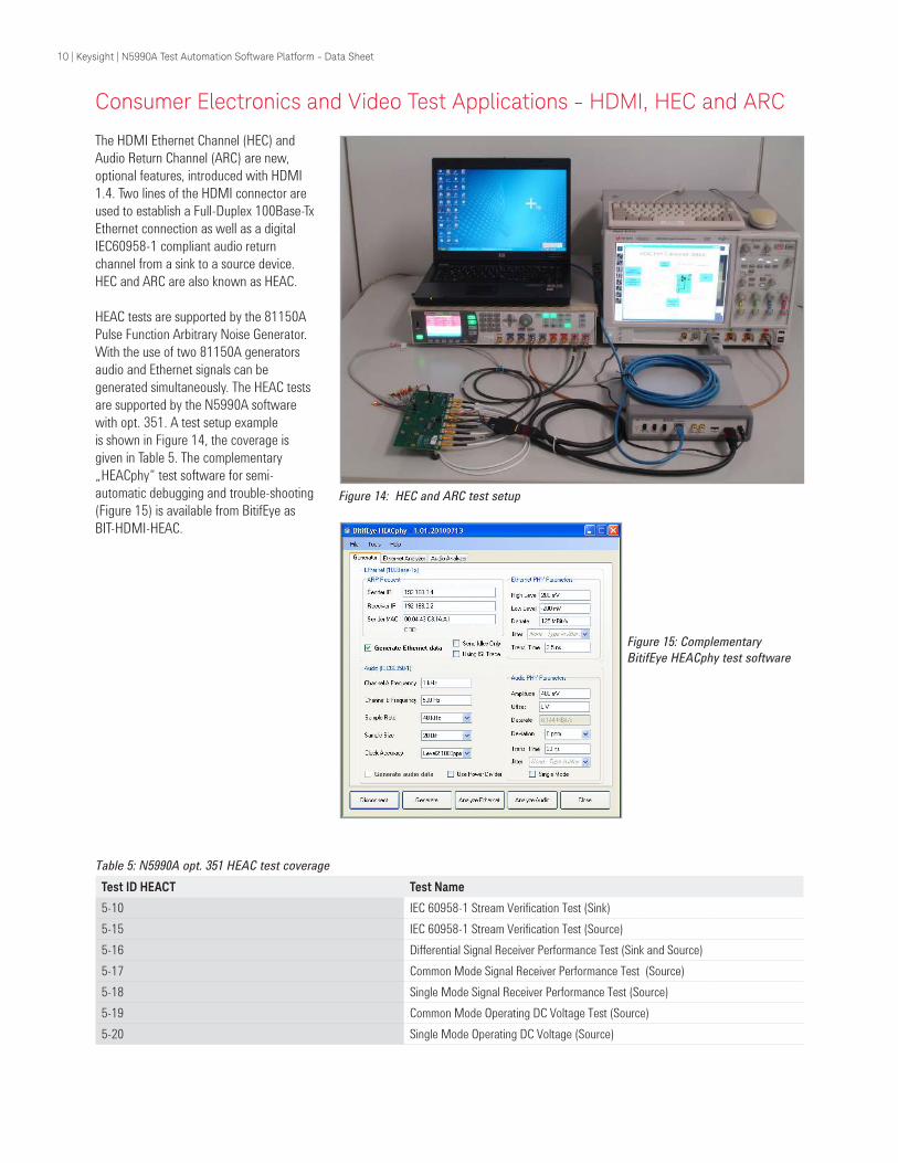
Table 5: N5990A opt. 351 HEAC test coverage
Test ID HEACT Test Name
5-10 IEC 60958-1 Stream Verification Test (Sink)
5-15 IEC 60958-1 Stream Verification Test (Source)
5-16 Differential Signal Receiver Performance Test (Sink and Source)
5-17 Common Mode Signal Receiver Performance Test (Source)
5-18 Single Mode Signal Receiver Performance Test (Source)
5-19 Common Mode Operating DC Voltage Test (Source)
5-20 Single Mode Operating DC Voltage (Source)
The HDMI Ethernet Channel (HEC) and
Audio Return Channel (ARC) are new,
optional features, introduced with HDMI
1.4. Two lines of the HDMI connector are
used to establish a Full-Duplex 100Base-Tx
Ethernet connection as well as a digital
IEC60958-1 compliant audio return
channel from a sink to a source device.
HEC and ARC are also known as HEAC.
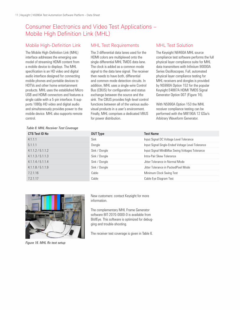
HEAC tests are supported by the 81150A
Pulse Function Arbitrary Noise Generator.
With the use of two 81150A generators
audio and Ethernet signals can be
generated simultaneously. The HEAC tests
are supported by the N5990A software
with opt. 351. A test setup example
is shown in Figure 14, the coverage is
given in Table 5. The complementary
„HEACphy“ test software for semi-
automatic debugging and trouble-shooting
(Figure 15) is available from BitifEye as
BIT-HDMI-HEAC.
Figure 14: HEC and ARC test setup
Figure 15: Complementary
BitifEye HEACphy test software
Consumer Electronics and Video Test Applications - HDMI, HEC and ARC
10 | Keysight | N5990A Test Automation Software Platform - Data Sheet
Mobile High-Deinition LinkThe Mobile High-Definition Link (MHL)
interface addresses the emerging use
model of streaming HDMI content from
a mobile device to displays. The MHL
specification is an HD video and digital
audio interface designed for connecting
mobile phones and portable devices to
HDTVs and other home entertainment
products. MHL uses the established Micro
USB and HDMI connectors and features a
single cable with a 5-pin interface. It sup-
ports 1080p HD video and digital audio
and simultaneously provides power to the
mobile device. MHL also supports remote
control.
Consumer Electronics and Video Test Applications – Mobile High Deinition Link (MHL)
MHL Test Requirements
The 3 differential data lanes used for the
HDMI colors are multiplexed onto the
single differential MHL TMDS data lane.
The clock is added as a common mode
signal to the data lane signal. The receiver
then needs to have both, differential
and common mode detection circuits. In
addition, MHL uses a single-wire Control
Bus (CBUS) for configuration and status
exchange between the source and the
sink. The CBUS provides high-level control
functions between all of the various audio-
visual products in a user’s environment.
Finally, MHL comprises a dedicated VBUS
for power distribution.
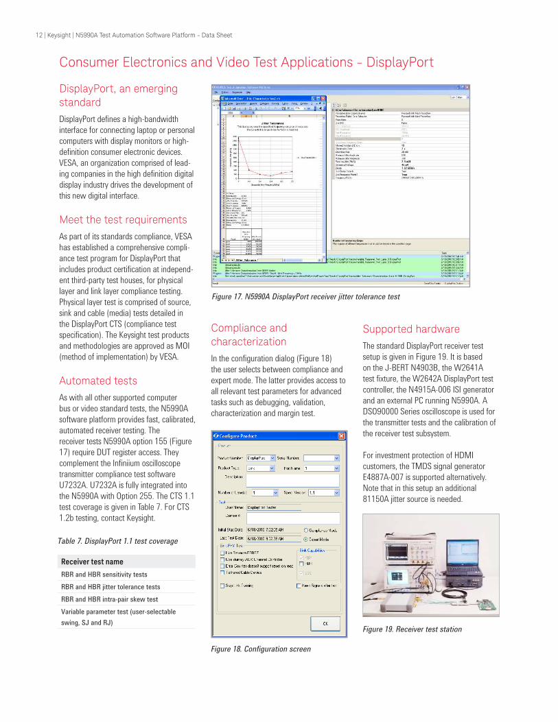
MHL Test Solution
The Keysight N6460A MHL source
compliance test software performs the full
physical layer compliance suite for MHL
data transmitters with Infiniium 90000A
Series Oscilloscopes. Full, automated
physical layer compliance testing for
MHL receivers and dongles is provided
by N5990A Option 152 for the popular
Keysight E4887A HDMI TMDS Signal
Generator Option 007 (Figure 16).
With N5990A Option 153 the MHL
receiver compliance testing can be
performed with the M8190A 12 GSa/s
Arbitrary Waveform Generator.
Figure 16. MHL Rx test setup
New customers: contact Keysight for more
information.
The complementary MHL Frame Generator
software BIT-2070-0000-0 is available from
BitifEye. This software is optimized for debug-
ging and trouble-shooting.
The receiver test coverage is given in Table 6.
Table 6: MHL Receiver Test Coverage
CTS Test ID No DUT Type Test Name
4.1.1.1 Sink Input Signal DC Voltage Level Tolerance
5.1.1.1 Dongle Input Signal Single-Ended Voltage Level Tolerance
4.1.1.2 / 5.1.1.2 Sink / Dongle Input Signal Min&Max Swing Voltages Tolerance
4.1.1.3 / 5.1.1.3 Sink / Dongle Intra-Pair Skew Tolerance
4.1.1.4 / 5.1.1.4 Sink / Dongle Jitter Tolerance in Normal Mode
4.1.1.8 / 5.1.1.9 Sink / Dongle Jitter Tolerance in PackedPixel Mode
7.2.1.16 Cable Minimum Clock Swing Test
7.2.1.17 Cable Cable Eye Diagram Test
11 | Keysight | N5990A Test Automation Software Platform - Data Sheet
DisplayPort, an emerging standard
DisplayPort defines a high-bandwidth
interface for connecting laptop or personal
computers with display monitors or high-
definition consumer electronic devices.
VESA, an organization comprised of lead-
ing companies in the high definition digital
display industry drives the development of
this new digital interface.
Meet the test requirements
As part of its standards compliance, VESA
has established a comprehensive compli-
ance test program for DisplayPort that
includes product certification at independ-
ent third-party test houses, for physical
layer and link layer compliance testing.
Physical layer test is comprised of source,
sink and cable (media) tests detailed in
the DisplayPort CTS (compliance test
specification). The Keysight test products
and methodologies are approved as MOI
(method of implementation) by VESA.
Automated tests
As with all other supported computer
bus or video standard tests, the N5990A
software platform provides fast, calibrated,
automated receiver testing. The
receiver tests N5990A option 155 (Figure
17) require DUT register access. They
complement the Infiniium oscilloscope
transmitter compliance test software
U7232A. U7232A is fully integrated into
the N5990A with Option 255. The CTS 1.1
test coverage is given in Table 7. For CTS
1.2b testing, contact Keysight.
Compliance and characterization
In the configuration dialog (Figure 18)
the user selects between compliance and
expert mode. The latter provides access to
all relevant test parameters for advanced
tasks such as debugging, validation,
characterization and margin test.
Figure 17. N5990A DisplayPort receiver jitter tolerance test
Figure 18. Configuration screen
Supported hardware
The standard DisplayPort receiver test
setup is given in Figure 19. It is based
on the J-BERT N4903B, the W2641A
test fixture, the W2642A DisplayPort test
controller, the N4915A-006 ISI generator
and an external PC running N5990A. A
DSO90000 Series oscilloscope is used for
the transmitter tests and the calibration of
the receiver test subsystem.
For investment protection of HDMI
customers, the TMDS signal generator
E4887A-007 is supported alternatively.
Note that in this setup an additional
81150A jitter source is needed.
Figure 19. Receiver test station
Table 7. DisplayPort 1.1 test coverage
Receiver test name
RBR and HBR sensitivity tests
RBR and HBR jitter tolerance tests
RBR and HBR intra-pair skew test
Variable parameter test (user-selectable
swing, SJ and RJ)
Consumer Electronics and Video Test Applications - DisplayPort
12 | Keysight | N5990A Test Automation Software Platform - Data Sheet
Mobile Device Interface Test Applications – MIPI D-PHY
MIPI, the mobile standard
The Mobile Industry Processor Interface
(MIPI™) Alliance is an open membership
organization that includes leading compa-
nies in the mobile industry that share the
objective of defining and promoting open
specifications for interfaces in mobile termi-
nals. MIPI specifications establish standards
for hardware and software interfaces
between the processors and peripherals
typically found in mobile terminal systems
such as cell phones. MIPI D-PHY currently
operates at up to 1.5 Gb/s per lane. The
data rate may increase in the future.
Meet the test requirements
As part of its standards compliance, the
MIPI Alliance has established a compre-
hensive compliance test program for MIPI
D-PHY that includes product certification
at independent third-party test houses for
physical layer and link layer compliance
testing. Physical layer test is comprised of
receiver and transmitter tests detailed in
the MIPI D-PHY compliance test suite. The
Keysight test products and methodologies
are approved as MOI (method of imple-
mentation) by the MIPI Alliance.
Automated tests
Like for all other supported computer bus
or video standard tests, the N5990A soft-
ware platform provides fast, calibrated,
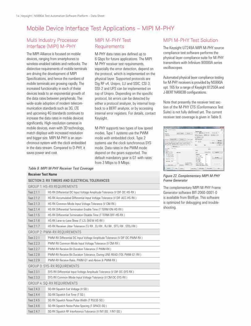
Supported hardware
The standard MIPI receiver test setup
is shown in Figure 21. It is based on a
ParBERT 81250A with external clock, jitter
and noise sources, a logic analyzer, an
oscilloscope and an external PC running
the N5990A software.
For investment protection of HDMI and
DisplayPort customers, the MIPI receiver
test configurations are available as
extensions of the TMDS signal generators,
E4887A.
The source tests are conducted with
DSO90000A Series oscilloscopes. The
oscilloscope is used for the calibration of
the receiver test subsystem, too.
Figure 21. Receiver test station
Figure 20. Complementary MIPI frame generator
Table 8. MIPI D-PHY 1.1 test coverage
Receiver Test Name
Group 1: LP-Rx Voltage and
Timing Requirements
Test IDs: 2.1.1, 2.1.2, 2.1.3 2.1.4,
2.1.5, 2.1.6, 2.1.7, 2.1.8
Group 2: LP-Rx Behavioral
Requirements
Test IDs: 2.2.1, 2.2.2, 2.2.3, 2.2.4,
2.2.5, 2.2.6, 2.2.7, 2.2.8
Group 3: HS-Rx Voltage and
Setup/Hold Requirements
Test IDs: 2.3.1, 2.3.2, 2.3.3, 2.3.4,
2.3.5, 2.3.6, 2.3.7, 2.3.8
Group 4: HS-Rx Timer
Requirements
Test IDs: 2.4.1, 2.4.2, 2.4.3, 2.4.4,
2.4.5, 2.4.6, 2.4.7, 2.4.8, 2.4.9,
2.4.10, 2.4.11
automated testing. The coverage of the
receiver tests, N5990A Option 160 is
shown in Table 8. They complement the
Infiniium oscilloscope transmitter compli-
ance test software U7238A. U7238A
is fully integrated into N5990A with
Option 260. The test automation software
provides compliance tests and device
characterization, incl. margin test.
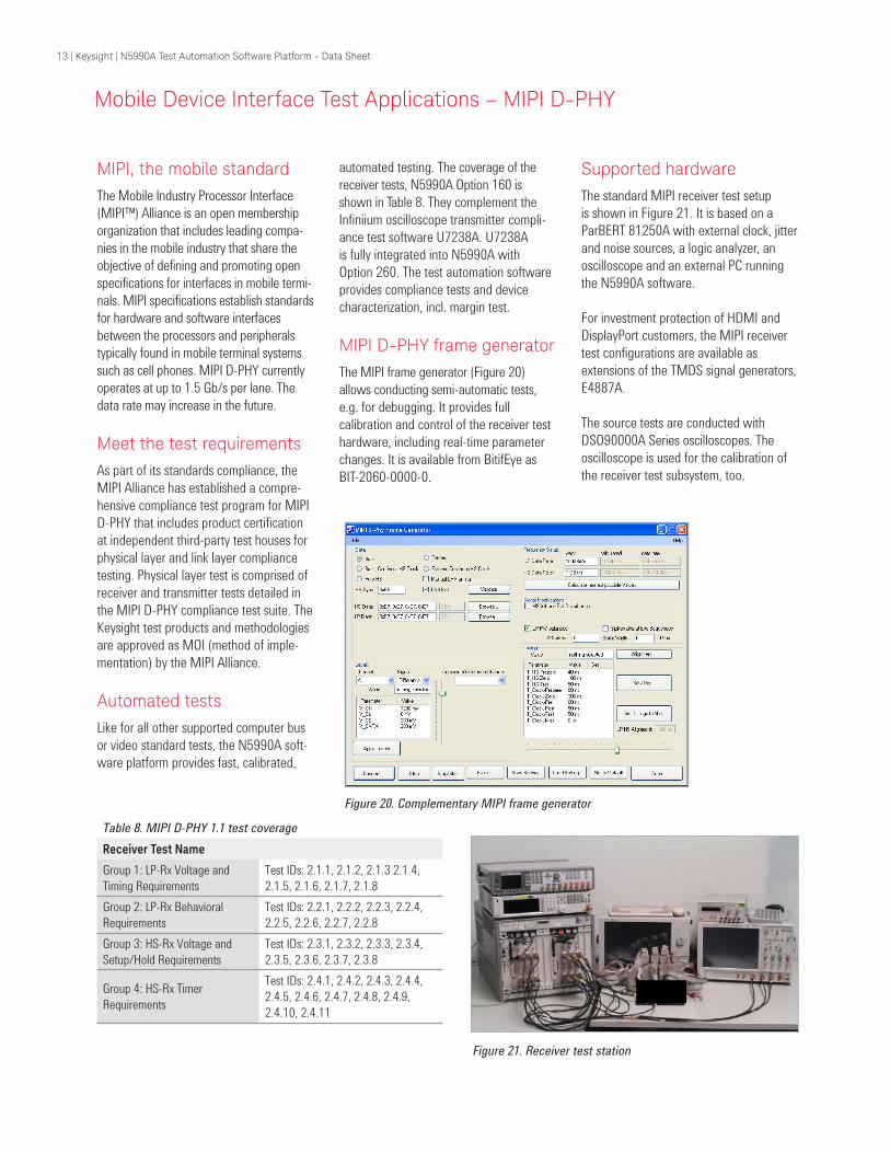
MIPI D-PHY frame generator
The MIPI frame generator (Figure 20)
allows conducting semi-automatic tests,
e.g. for debugging. It provides full
calibration and control of the receiver test
hardware, including real-time parameter
changes. It is available from BitifEye as
BIT-2060-0000-0.
13 | Keysight | N5990A Test Automation Software Platform - Data Sheet
Mobile Device Interface Test Applications – MIPI M-PHY
Multi Industry Processor Interface (MIPI) M-PHY
The MIPI Alliance is focused on mobile
devices, ranging from smartphones to
wireless-enabled tablets and netbooks. The
distinctive requirements of mobile terminals
are driving the development of MIPI
Specifications, and hence the numbers of
mobile terminals are growing rapidly. The
increased functionality in each of these
devices leads to an exponential growth of
the data rates between peripherals. The
wide-scale adoption of modern telecom-
munication standards such as 3G, LTE
and upcoming 4G standards continues to
increase the data rates in mobile devices
significantly. High-resolution cameras in
mobile devices, even with 3D technology,
match displays with increased resolution
and bigger size. MIPI M-PHY is an asyn-
chronous system with the clock embedded
in the data stream. Compared to D-PHY, it
saves power and cost.
MIPI M-PHY Test Requirements
M-PHY data rates are defined up to
6 Gbps for future applications. The MIPI
M-PHY receiver test requirements,
especially the error detection, depend on
the protocol, which is implemented on the
physical layer. Supported protocols are
Dig RF v4, Unipro, LLI and SSIC. CSI-3,
DSI-2 and UFS can be implemented on
top of Unipro. Depending on the specific
protocol, bit errors can be detected by
either a protocol analyzer, by internal loop-
back to a BERT analyzer, or by accessing
internal error registers. For details, contact
Keysight.
M-PHY supports two types of low speed
modes. Type 1 systems use the PWM
mode with embedded clock. Type 2
systems use the clock synchronous SYS
mode. Data rates in the PWM mode
depend on the gears supported. The
default mandatory gear is G1 with rates
from 3 Mbps to 9 Mbps.
MIPI M-PHY Test Solution
The Keysight U7249A MIPI M-PHY source
compliance test software performs the
physical layer compliance suite for M-PHY
transmitters with Infiniium 90000A series
oscilloscopes.
Automated physical layer compliance testing
for M-PHY receivers is provided by N5990A
opt. 165 for a range of Keysight 81250A and
J-BERT N4903B configurations.
Note that presently the receiver test sec-
tion of the M-PHY CTS (Conformance Test
Suite) is not fully defined yet. The current
receiver test coverage is given in Table 9.
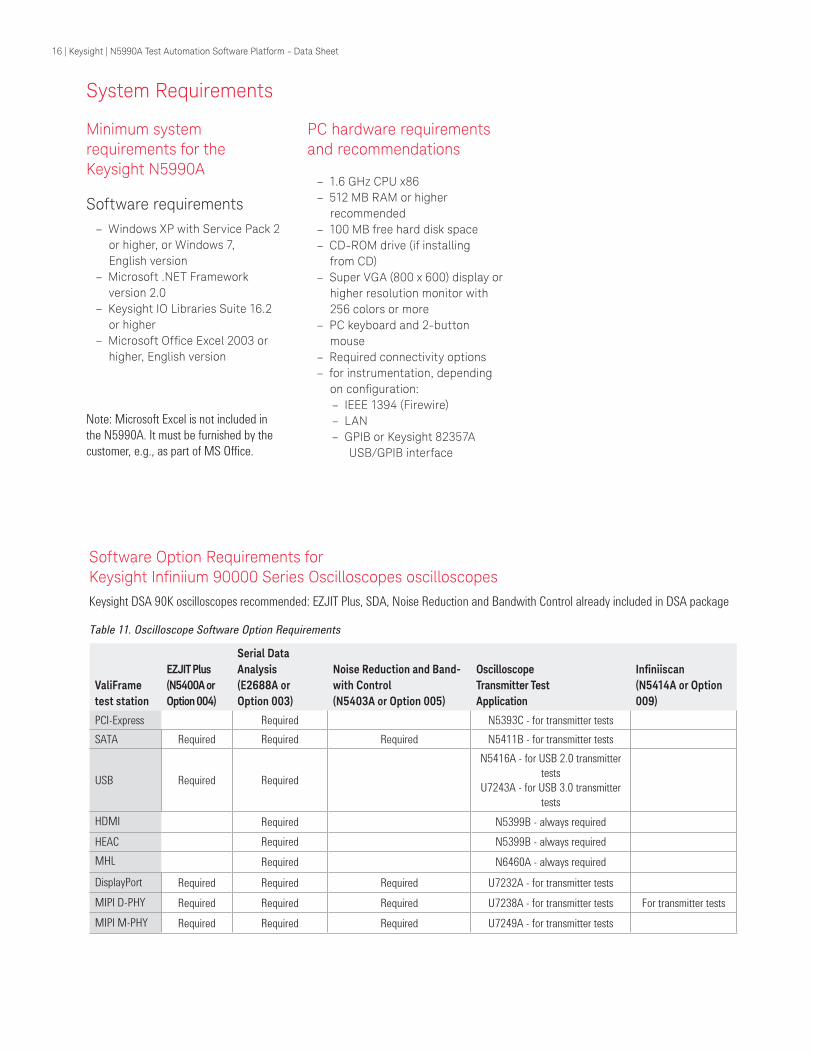
Figure 22. Complementary MIPI M-PHY
Frame Generator
The complementary MIPI M-PHY Frame
Generator software BIT-2060-0001-0
is available from BitifEye. This software
is optimized for debugging and trouble-
shooting.
Table 9: MIPI M-PHY Receiver Test Coverage
Receiver Test Name
SECTION 2: RX TIMERS AND ELECTRICAL TOLERANCES
GROUP 1: HS-RX REQUIREMENTS
Test 2.1.1 HS-RX Differential DC Input Voltage Amplitude Tolerance (V DIF-DC-HS-RX )
Test 2.1.2 HS-RX Accumulated Differential Input Voltage Tolerance (V DIF-ACC-HS-RX )
Test 2.1.3 HS-RX Common-Mode Input Voltage Tolerance (V CM-RX )
Test 2.1.4 HS-RX Differential Termination Enable Time (T TERM-ON-HS-RX )
Test 2.1.5 HS-RX Differential Termination Disable Time (T TERM-OFF-HS-RX )
Test 2.1.6 HS-RX Lane-to-Lane Skew (T L2L-SKEW-HS-RX )
Test 2.1.7 HS-RX Receiver Jitter Tolerance (TJ RX , DJ RX , RJ RX , STTJ RX , STDJ RX )
GROUP 2: PWM-RX REQUIREMENTS
Test 2.2.1 PWM-RX Differential DC Input Voltage Amplitude Tolerance (V DIF-DC-PWM-RX )
Test 2.2.3 PWM-RX Common-Mode Input Voltage Tolerance (V CM-RX )
Test 2.2.7 PWM-RX Receive Bit Duration Tolerance (T PWM-RX )
Test 2.2.8 PWM-RX Receive Bit Duration Tolerance, During LINE-READ (TOL PWM-G1-RX )
Test 2.2.9 PWM-RX Receive Ratio, PWM-G1 and Above (k PWM-RX )
GROUP 3: SYS-RX REQUIREMENTS
Test 2.3.1 SYS-RX Differential Input Voltage Amplitude Tolerance (V DIF-DC-SYS-RX )
Test 2.3.3 SYS-RX Common-Mode Input Voltage Tolerance (V CM-DC-SYS-RX )
GROUP 4: SQ-RX REQUIREMENTS
Test 2.4.3 SQ-RX Squelch Exit Voltage (V SQ )
Test 2.4.4 SQ-RX Squelch Exit Time (T SQ )
Test 2.4.5 SQ-RX Squelch Noise Pulse Width (T PULSE-SQ )
Test 2.4.6 SQ-RX Squelch Noise Pulse Spacing (T SPACE-SQ )
Test 2.4.7 SQ-RX Squelch RF Interference Tolerance (V INT-SQ , f INT-SQ )
14 | Keysight | N5990A Test Automation Software Platform - Data Sheet

The following instruments are supported for the applications indicated.
Instrument Compatibility
Table 10. Instrument compatibility (Keysight instruments if no vendor mentioned)
Recommended
instrumentRemark
PCI
ExpressSATA
USB
3.0HDMI MHL DisplayPort
MIPI
D-PHY
MIPI
M-PHY
TMDS
Signal
Gen-
erator
HEAC
Arbitrary
Wave-
form
Genera-
tor
ParBERT J-BERT
Generator
81250 ParBERT
3.3 Gb/s, 7 Gb/s or
13.5 Gb/s; external jitter
sources required, contact
Keysight
x1 x x1, 2 x x
N4903B J-BERT
7 Gb/s or 12.5 Gb/s,
integrated PJ, SJ, RJ
and SSC generation
x3 x x x x
M8190A-002
Arbitrary Waveform
Generator
12 GSa/s, 5 GHz analog
bandwidthx x
81150A-002
120 MHz pulse/
pattern generation with
variable rise/fall time
x
Error detector / Error counter
N4903B-C07 or
N4903B-C13 x x x x5
N4903B-A02 x x
SerialTek BusXpert x4
Ellisys USB Explorer x
1. Configurations and specifications: see E4887A data sheet (5989-5537EN)
2. E4887A-003 not supported
3. Additional 81150A required for Gen3 ASIC tests
4. Additional error detectors supported for SATA 1.5 Gb/s and 3 Gb/s, contact Keysight
5. Oscilloscope required for the calibration of the receiver test system
6. N5990A supports Keysight Infiniium oscilloscopes through the electrical performance specification applications, transmitter tests and compliance
software applications shown to the right. Additional oscilloscope options may be required. Refer to Table 11.
Oscilloscope5, 6 N5393B U5411B U7243A N5399B N6460A U7232A U7238A
DSO-X x x x x x x x x x x
DSA91304A 13 GHz x x x x x x x x x x
DSA91204A 12 GHz x x x x x x x x x x
DSA90804A 8 GHz x x x x x x x x
DSA90604A 6 GHz x x x x x x x x
DSO9404A 4 GHz x
15 | Keysight | N5990A Test Automation Software Platform - Data Sheet
Minimum system requirements for the Keysight N5990A
Software requirements
– Windows XP with Service Pack 2
or higher, or Windows 7,
English version
– Microsoft .NET Framework
version 2.0
– Keysight IO Libraries Suite 16.2
or higher
– Microsoft Ofice Excel 2003 or higher, English version
Note: Microsoft Excel is not included in
the N5990A. It must be furnished by the
customer, e.g., as part of MS Office.
System Requirements
PC hardware requirements and recommendations
– 1.6 GHz CPU x86
– 512 MB RAM or higher
recommended
– 100 MB free hard disk space
– CD-ROM drive (if installing
from CD)
– Super VGA (800 x 600) display or
higher resolution monitor with
256 colors or more
– PC keyboard and 2-button
mouse
– Required connectivity options
– for instrumentation, depending
on coniguration: – IEEE 1394 (Firewire)
– LAN
– GPIB or Keysight 82357A
USB/GPIB interface
ValiFrame
test station
EZJIT Plus
(N5400A or
Option 004)
Serial Data
Analysis
(E2688A or
Option 003)
Noise Reduction and Band-
with Control
(N5403A or Option 005)
Oscilloscope
Transmitter Test
Application
Ininiiscan(N5414A or Option
009)
PCI-Express Required N5393C - for transmitter tests
SATA Required Required Required N5411B - for transmitter tests
USB Required Required
N5416A - for USB 2.0 transmitter
tests
U7243A - for USB 3.0 transmitter
tests
HDMI Required N5399B - always required
HEAC Required N5399B - always required
MHL Required N6460A - always required
DisplayPort Required Required Required U7232A - for transmitter tests
MIPI D-PHY Required Required Required U7238A - for transmitter tests For transmitter tests
MIPI M-PHY Required Required Required U7249A - for transmitter tests
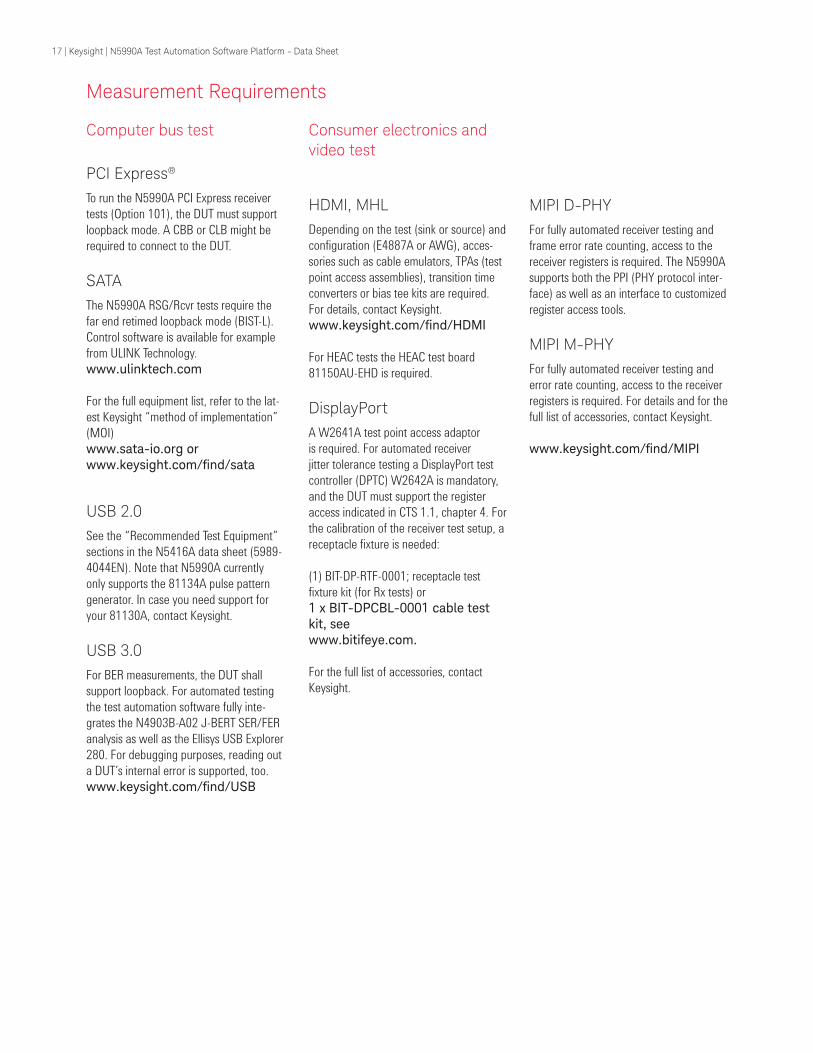
Software Option Requirements for Keysight Ininiium 90000 Series Oscilloscopes oscilloscopes Keysight DSA 90K oscilloscopes recommended: EZJIT Plus, SDA, Noise Reduction and Bandwith Control already included in DSA package
Table 11. Oscilloscope Software Option Requirements
16 | Keysight | N5990A Test Automation Software Platform - Data Sheet
Measurement Requirements
Consumer electronics and video test
HDMI, MHL
Depending on the test (sink or source) and
configuration (E4887A or AWG), acces-
sories such as cable emulators, TPAs (test
point access assemblies), transition time
converters or bias tee kits are required.
For details, contact Keysight.
www.keysight.com/find/HDMI
For HEAC tests the HEAC test board
81150AU-EHD is required.
DisplayPort
A W2641A test point access adaptor
is required. For automated receiver
jitter tolerance testing a DisplayPort test
controller (DPTC) W2642A is mandatory,
and the DUT must support the register
access indicated in CTS 1.1, chapter 4. For
the calibration of the receiver test setup, a
receptacle fixture is needed:
(1) BIT-DP-RTF-0001; receptacle test
fixture kit (for Rx tests) or
1 x BIT-DPCBL-0001 cable test kit, see www.bitifeye.com.
For the full list of accessories, contact
Keysight.
Computer bus test
PCI Express®
To run the N5990A PCI Express receiver
tests (Option 101), the DUT must support
loopback mode. A CBB or CLB might be
required to connect to the DUT.
SATA
The N5990A RSG/Rcvr tests require the
far end retimed loopback mode (BIST-L).
Control software is available for example
from ULINK Technology.
www.ulinktech.com
For the full equipment list, refer to the lat-
est Keysight “method of implementation”
(MOI)
www.sata-io.org or www.keysight.com/find/sata
USB 2.0
See the “Recommended Test Equipment”
sections in the N5416A data sheet (5989-
4044EN). Note that N5990A currently
only supports the 81134A pulse pattern
generator. In case you need support for
your 81130A, contact Keysight.
USB 3.0
For BER measurements, the DUT shall
support loopback. For automated testing
the test automation software fully inte-
grates the N4903B-A02 J-BERT SER/FER
analysis as well as the Ellisys USB Explorer
280. For debugging purposes, reading out
a DUT’s internal error is supported, too.
www.keysight.com/find/USB
MIPI D-PHY
For fully automated receiver testing and
frame error rate counting, access to the
receiver registers is required. The N5990A
supports both the PPI (PHY protocol inter-
face) as well as an interface to customized
register access tools.
MIPI M-PHY
For fully automated receiver testing and
error rate counting, access to the receiver
registers is required. For details and for the
full list of accessories, contact Keysight.
www.keysight.com/find/MIPI
17 | Keysight | N5990A Test Automation Software Platform - Data Sheet
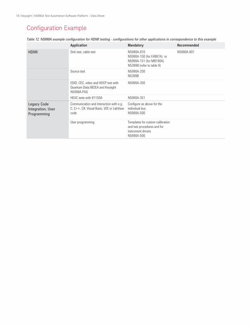
Coniguration Example
Table 12. N5990A example configuration for HDMI testing - configurations for other applications in correspondence to this example
Application Mandatory Recommended
HDMI Sink test, cable test N5990A-010
N5990A-150 (for E4887A) or
N5990A-151 (for M8190A)
N5399B (refer to table 9)
N5990A-001
Source test N5990A-250
N5399B
EDID, CEC, video and HDCP test with
Quantum Data 882EA and Keysight
N5998A PAG
N5990A-350
HEAC tests with 81150A N5990A-351
Legacy Code
Integration, User
Programming
Communication and interaction with e.g.
C, C++, C#, Visual Basic, VEE or LabView
code
Configure as above for the
individual bus,
N5990A-500
User programming Templates for custom calibration
and test procedures and for
instrument drivers
N5990A-500
18 | Keysight | N5990A Test Automation Software Platform - Data Sheet
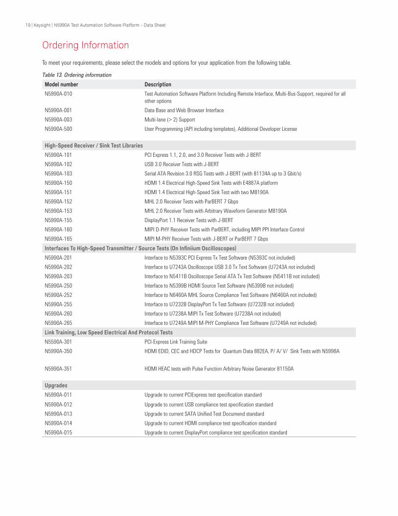
To meet your requirements, please select the models and options for your application from the following table.
Ordering Information
Table 13. Ordering information
Model number Description
N5990A-010 Test Automation Software Platform Including Remote Interface, Multi-Bus-Support, required for all
other options
N5990A-001 Data Base and Web Browser Interface
N5990A-003 Multi-lane (> 2) Support
N5990A-500 User Programming (API including templates), Additional Developer License
High-Speed Receiver / Sink Test Libraries
N5990A-101 PCI Express 1.1, 2.0, and 3.0 Receiver Tests with J-BERT
N5990A-102 USB 3.0 Receiver Tests with J-BERT
N5990A-103 Serial ATA Revision 3.0 RSG Tests with J-BERT (with 81134A up to 3 Gbit/s)
N5990A-150 HDMI 1.4 Electrical High-Speed Sink Tests with E4887A platform
N5990A-151 HDMI 1.4 Electrical High-Speed Sink Test with two M8190A
N5990A-152 MHL 2.0 Receiver Tests with ParBERT 7 Gbps
N5990A-153 MHL 2.0 Receiver Tests with Arbitrary Waveform Generator M8190A
N5990A-155 DisplayPort 1.1 Receiver Tests with J-BERT
N5990A-160 MIPI D-PHY Receiver Tests with ParBERT, including MIPI PPI Interface Control
N5990A-165 MIPI M-PHY Receiver Tests with J-BERT or ParBERT 7 Gbps
Interfaces To High-Speed Transmitter / Source Tests (On Ininiium Oscilloscopes)
N5990A-201 Interface to N5393C PCI Express Tx Test Software (N5393C not included)
N5990A-202 Interface to U7243A Oscilloscope USB 3.0 Tx Text Software (U7243A not included)
N5990A-203 Interface to N5411B Oscilloscope Serial ATA Tx Test Software (N5411B not included)
N5990A-250 Interface to N5399B HDMI Source Test Software (N5399B not included)
N5990A-252 Interface to N6460A MHL Source Compliance Test Software (N6460A not included)
N5990A-255 Interface to U7232B DisplayPort Tx Test Software (U7232B not included)
N5990A-260 Interface to U7238A MIPI Tx Test Software (U7238A not included)
N5990A-265 Interface to U7249A MIPI M-PHY Compliance Test Software (U7249A not included)
Link Training, Low Speed Electrical And Protocol Tests
N5590A-301 PCI-Express Link Training Suite
N5990A-350 HDMI EDID, CEC and HDCP Tests for Quantum Data 882EA, P/ A/ V/ Sink Tests with N5998A
N5990A-351 HDMI HEAC tests with Pulse Function Arbitrary Noise Generator 81150A
Upgrades
N5990A-011 Upgrade to current PCIExpress test specification standard
N5990A-012 Upgrade to current USB compliance test specification standard
N5990A-013 Upgrade to current SATA Unified Test Documend standard
N5990A-014 Upgrade to current HDMI compliance test specification standard
N5990A-015 Upgrade to current DisplayPort compliance test specification standard
19 | Keysight | N5990A Test Automation Software Platform - Data Sheet
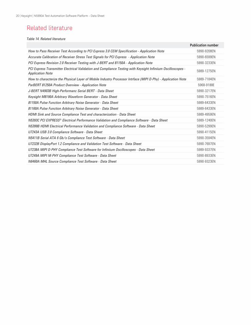
Publication number
How to Pass Receiver Test According to PCI Express 3.0 CEM Specification - Application Note 5990-9208EN
Accurate Calibration of Receiver Stress Test Signals for PCI Express - Application Note 5990-6599EN
PCI Express Revision 2.0 Receiver Testing with J-BERT and 81150A - Application Note 5990-3233EN
PCI Express Transmitter Electrical Validation and Compliance Testing with Keysight Infiniium Oscilloscopes -
Application Note5989-1275EN
How to characterize the Physical Layer of Mobile Industry Processor Intrface (MIPI D-Phy) - Application Note 5989-7184EN
ParBERT 81250A Product Overview - Application Note 5968-9188E
J-BERT N4903B High-Performanc Serial BERT - Data Sheet 5990-3217EN
Keysight M8190A Arbitrary Waveform Generator - Data Sheet 5990-7516EN
81150A Pulse Function Arbitrary Noise Generator - Data Sheet 5989-6433EN
81160A Pulse Function Arbitrary Noise Generator - Data Sheet 5989-6433EN
HDMI Sink and Source Compliance Test and characterization - Data Sheet 5989-4959EN
N5393C PCI EXPRESS® Electrical Performance Validation and Compliance Software - Data Sheet 5989-1240EN
N5399B HDMI Electrical Performance Validation and Compliance Software - Data Sheet 5990-5299EN
U7243A USB 3.0 Compliance Software - Data Sheet 5990-4115EN
N5411B Serial ATA 6 Gb/s Compliance Test Software - Data Sheet 5990-3594EN
U7232B DisplayPort 1.2 Compliance and Validation Test Software - Data Sheet 5990-7697EN
U7238A MIPI D-PHY Compliance Test Software for Infiniium Oscilloscopes - Data Sheet 5989-9337EN
U7249A MIPI M-PHY Compliance Test Software - Data Sheet 5990-8933EN
N6460A MHL Source Compliance Test Software - Data Sheet 5990-9323EN
Related literature
Table 14. Related literature
20 | Keysight | N5990A Test Automation Software Platform - Data Sheet
For more information on Keysight
Technologies’ products, applications or
services, please contact your local Keysight
office. The complete list is available at:www.keysight.com/find/contactus
Americas
Canada (877) 894 4414Brazil 55 11 3351 7010Mexico 001 800 254 2440United States (800) 829 4444
Asia PaciicAustralia 1 800 629 485China 800 810 0189Hong Kong 800 938 693India 1 800 112 929Japan 0120 (421) 345Korea 080 769 0800Malaysia 1 800 888 848Singapore 1 800 375 8100Taiwan 0800 047 866Other AP Countries (65) 6375 8100
Europe & Middle East
Austria 0800 001122Belgium 0800 58580Finland 0800 523252France 0805 980333Germany 0800 6270999Ireland 1800 832700Israel 1 809 343051Italy 800 599100Luxembourg +32 800 58580Netherlands 0800 0233200Russia 8800 5009286Spain 0800 000154Sweden 0200 882255Switzerland 0800 805353
Opt. 1 (DE)Opt. 2 (FR)Opt. 3 (IT)
United Kingdom 0800 0260637
For other unlisted countries:www.keysight.com/find/contactus
(BP-07-10-14)
21 | Keysight | N5990A Test Automation Software Platform - Data Sheet
myKeysight
www.keysight.com/find/mykeysight
A personalized view into the information most relevant to you.
www.axiestandard.org
AdvancedTCA® Extensions for Instrumentation and Test (AXIe) is an
open standard that extends the AdvancedTCA for general purpose and
semiconductor test. Keysight is a founding member of the AXIe consortium.
ATCA®, AdvancedTCA®, and the ATCA logo are registered US trademarks of
the PCI Industrial Computer Manufacturers Group.
www.lxistandard.org
LAN eXtensions for Instruments puts the power of Ethernet and the
Web inside your test systems. Keysight is a founding member of the LXI
consortium.
www.pxisa.org
PCI eXtensions for Instrumentation (PXI) modular instrumentation delivers a
rugged, PC-based high-performance measurement and automation system.
Three-Year Warranty
www.keysight.com/find/ThreeYearWarranty
Keysight’s commitment to superior product quality and lower total cost
of ownership. The only test and measurement company with three-year
warranty standard on all instruments, worldwide.
Keysight Assurance Plans
www.keysight.com/find/AssurancePlans
Up to five years of protection and no budgetary surprises to ensure your
instruments are operating to specification so you can rely on accurate
measurements.
www.keysight.com/quality
Keysight Technologies, Inc.
DEKRA Certified ISO 9001:2008 Quality Management System
Keysight Channel Partners
www.keysight.com/find/channelpartners
Get the best of both worlds: Keysight’s measurement expertise and product breadth, combined with channel partner convenience.
www.keysight.com/find/automation
MIPI is a licensed trademark of MIPI, Inc. in the U.S. and other jurisdictions.
PCI-SIG®, PCIe® and the PCI Express® are registered U.S. trademarks and/or service
marks of PCI-SIG.
This information is subject to change without notice.© Keysight Technologies, 2013 - 2014Published in USA, August 3, 20145989-5483ENwww.keysight.com