keysight technologies n6841a rf sensor for signal ... rf sensor for... · keysight technologies...
TRANSCRIPT

Keysight TechnologiesN6841A RF Sensorfor Signal Monitoring Networks
Data Sheet

2
– Environmentally rugged IP67-rated weatherproof enclosure. Sealed unit with no moving internal parts
– Small footprint for ease of setup and teardown – Wideband RF receiver with 20 MHz to 6 GHz frequency range – Optional third party frequency extender can be purchased to increase fre-
quency range from 100 kHz to 27.4 GHz – Digital IF bandwidth adjustable up to 20 MHz – Signal LOOKback memory (4.8 secs at 20 MHz BW)—enables reliable de-
tection, processing and location of short duration signals or interference – I/Q streaming up to 1.9 MHz bandwidth for recording or off board signal
processing – Integrated GPS for sensor location and time synchronous applications – High precision measurement synchronization and time-stamping – AM/FM demodulated audio streaming – Two Type-N RF input ports (switched) for multiple antennas – Well documented API for user programming and application development – WiderangeofSensorapplicationstomeetyourspecificmonitoring,analy-
sis or location requirements
“I’ve got bursting interfer-ers that need to be reliably detected,classified,identi-fiedandlocated.I’vealreadydone the easy ones with my older generation equip-ment…”
Key Features

3
Use Models for RF Sensors – Spectrumsurveywithsignalclassificationanddatabaseoperations – Interferencedetection,collection,classification,identification
and location – Band Clearing/spectrum occupancy/utilization monitoring – Border or regional area RF monitoring and geolocation – Range monitoring – Spectrum awareness associated with RF testing – Enforcing your organization’s spectrum policy
Customers – Military and Intelligence operations – Frequency Regulatory Agencies – Mobile Service Providers – Government Range Managers – Spectrum/Frequency Managers – RF Test Managers – Anyone monitoring or working with “off the air” RF signals
Measurements you can make with the RF Sensor and its ap-plications
– 24/7 Real time remote spectrum monitoring and analysis from the comfortofyouroffice
– High speed spectral search and signal isolation – I/Qrecordingandsignalclassification,demodulationanddecoding – Analog and digital signal analysis – Comprehensive ITU signal measurements – Emitter location – Custom applications using the Sensor Access Library (SAL) API
The Keysight Technologies, Inc.N6841A RF Sensor represents an entirely new concept in spectrum monitoring. Commu-nication signals have evolved dramatically and continue to do so as new and emerging wirelessstandardsaredefinedand deployed. These new generation signals are wider bandwidth, more complex, time variant and low power. Traditional methods of moni-toring communication signals from outside the city limits, a crowded vehicle or walking with a handheld analyzer just don’t work well on these new standards or today’s interfer-ence problems.
Overview
The Keysight N6841A RF Sensor offers a cost effective solution to placing a fully capable RF monitoring station where you need it, when you need it for as long as you need it, without-complex siting constraints or physical infrastructure.

4
Deployments
The N6841A RF Sensor has a weatherproof and dustproof IP67-rated (Standard IEC 60529 International Protection 67) enclosure plus a wide operating temperature range to withstand harsh environments without additional expensive protective enclosures. The unit is convection cooled, silent and contains no moving parts. It operates over a temperature range of –15 °C to 55 °C. The range can be extended by use of commercially available enclosures that provide heat and ventilation as needed for extreme temperature conditions.
This receiver has a small footprint with no external switches or status indicators making it extremely discreet. The low-profile form factor offers many mounting options, including tripod, roof-top, pole-top, rack-mount, vehicle-mount or man-pack deployments. Relative to other solutions, the N6841A RF Sensor requires a minimum of installation engineering, and is likely to gain easy approval for installation from building managers. It is also very well suited to temporary installations.
On-board diagnostics include complete self-test of the internal RF signal path and a watchdog reset timer. This reduces the need for on-site troubleshooting. Installation and configuration of the RF sensor is simple with only RF input, GPS antenna (optional), power and network connections.
More detailed information regarding installation is provided in the N6841A Installation Guide (Publication Number N6841-90002).
AntennasThe N6841A RF Sensor can be used with any passive or active antenna element. A specific antenna is not stipulated for use with the RF Sensor to ensure maximum flexibility of the solution. In most cases, a simple and low cost discone or dipole antenna works very well and provides enough coverage to make the measurements needed without excessive expense or additional power.
Power ConsiderationsThe N6841A RF Sensor is powered by DC voltage ranging from 15 to 24VDC and it draws less than 30W. Option SP1 provides a 120/240 VAC power supply suitable for indoor (protected) installations. Off-the-shelf batteries are available from a number of suppliers that can power the RF Sensor for up to eight hours. There are also power supplies rated for outdoor use available from various suppliers. The RF Sensor ships with an extra power connector for use with an alternate power source.
Network ConnectionsMany times, a wired Internet connection is not possible for the ideal RF Sensor location. In these cases, either a 3G or 4G modem or Wi-Fi backhaul may be an option. Standard Wi-Fi radios with directional antennas can easily service the data connection to an RF Sensor over 2.5 to 3km. If greater distances are needed, a cellular modem provides the freedom to site the sensor anywhere in the cellular coverage area. If wired Ethernet is available for your installation, shielded cable is highly recommended to reduce the chance of interference.
Physical MountingThe N6841A RF Sensor ships with a complete mounting kit for attachment to a rack, wall or pole. The mounting bracket includes provision for security locks, attachment of the GPS antenna and the RF Sensor. Aside from the RF Antenna, only one connection to the pole is required for a new RF monitoring station.
Multiple SensorsOne of the benefits of deploying multiple sensors is improved RF detection range and the ability to make time synchronous I/Q and spectral measurements. This capability opens the door to emitter location and direction finding applications, propagation studies and other applications. N6841A RF Sensors can be synchronized using two different methods: GPS (for outside deployments) and IEEE-1588 (for indoor deployments or wherever GPS may not be available).

5
Sensor Software Applications
Sensor Management Tool (SMT)The N6841A RF Sensor ships with the latest release of SMT. This application provides the user with a quick and easy way of setting up the RF Sensor remotely on their network, connecting, configuring and managing the sensor network. SMT also provides health and status monitoring of each sensor as well as a simple Spectrum Viewer and Radio application. This software is also available for download at www.keysight.com/find/RFSensor

6
Sensor Placement and Optimization Tool (SPOT)SPOT is supplied with SMT and is an invaluable tool for planning sensor deployments. SPOT allows a map image to be imported and calibrated then simulates the RF coverage that can be expected from the exact locations selected for the RF Sensor network. SPOT can determine how well the sensor network will perform against a specific radio transmitter by entering the center frequency, bandwidth and power output. Each sensor location is defined not only by its latitude and longitude, but also by elevation, antenna pattern, pre-amplifier effects as well as other parameters. SPOT also provides insight into the effectiveness of the sensor geometry in performing geolocation measurements. GDOP and lines of constant time or power can be displayed to aid in system design.
Sensor Software Applications

7
Spectrum AnalysisThe Keysight Spectrum Visualizer is a simple and easy to use application for performing classic spectrum analysis with the added benefit of recording I/Q data. The application can be purchased using the part number PX-X10-100.
Sensor Software Applications

8
Vector Signal Analysis (VSA)Keysight’s VSA software is an industry standard used throughout the wire-less communications and aerospace/defense industries for collection and processing of all forms of RF signals. It has an extensive library of wireless communications demodulators and decoders. The VSA software will turn the N6841A RF Sensor into a world class signal collection and analysis tool that can be operated literally from across the world.
Sensor Software Applications

9
Signal SurveyorThis application provides high speed spectral search, advanced energy detection and signal isolation algorithms. Depending on the option set, signal clas-sification and automated modulation recognition routines are also available. Automation of search, collection, classification and location tasks are possible with this powerful application. For a more detailed description of Signal Surveyor, visit www.keysight.com/find/N6820ES
Sensor Software Applications

10
Keysight GEO Server Software (GSS)GSS is a licensed application that embeds within SMT and enables the user to easily make geolocation measurements on signals of interest using either time or power based triggering. This application offers three different geolocation algorithms:
– Time Difference of Arrival (TDOA) – Received Signal Strength (RSS) – Hybrid (an adaptive algorithm that uses both time and power information)
GSS makes measurements either manually or automatically when integrated with Signal Surveyor. The results (including the I/Q data) are stored in a signals database to allow the user to revisit the geolocation measurements, try different algorithms and include or exclude data from any of the sensors used in the original measurement.
Sensor Software Applications

11
N6854A to KML SoftwareIncluded with GSS is a KML export tool which can refine the location results fur-ther and display them in commonly used geographic information systems. This powerful Geo-Analytics software package is an essential part of any modern spectrum monitoring system.
Sensor Software Applications
12
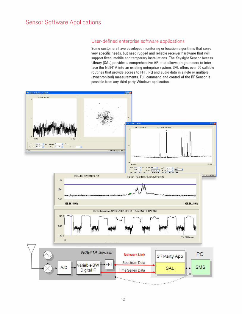
User-definedenterprisesoftwareapplicationsSome customers have developed monitoring or location algorithms that serve very specific needs, but need rugged and reliable receiver hardware that will support fixed, mobile and temporary installations. The Keysight Sensor Access Library (SAL) provides a comprehensive API that allows programmers to inter-face the N6841A into an existing enterprise system. SAL offers over 50 callable routines that provide access to FFT, I/Q and audio data in single or multiple (synchronized) measurements. Full command and control of the RF Sensor is possible from any third party Windows application.
Sensor Software Applications

13
Part number Description
RF Sensor HardwareN6841A RF Sensor Includes SMT, SPOT, KML software, connector and mounting kitN6841A-GPS Adds GPS capability, includes cable and active antennaN6841A-SP1 Adds 120/240 VAC power adapter (indoor mount only)N6841A-GFP Geolocation enablerN6841A-CFP Frequency extender enabler (3rd party frequency extender not included)
Signal SurveyorN6820ES Signal Surveyor Software for the RF SensorN6820ES-114 Basic Search, intercept and collection softwareN6820ES-SSY Synchronous Sweep enablerN6820ES-USD Universal Signal DetectorN6820ES-MR1 Host-Based Modulation RecognitionN6820ES-ASD User ProgrammingN6820ES-1RU 1 year of software updates and factory supportN6820ES-2RU 2 years of software updates and factory supportN6820ES-B02 Software bundle includes all options plus 1RU
Geolocation ServerN6854A Geolocation Server SoftwareN6854A-103 Basic software includes TDOA geolocation onlyN6854A-AG1 Optional power-based location algorithms (RSS and Hybrid)
Vector Signal Analyzer89601B Keysight Vector Signal Analyzer89601B-200 Basic software89601B-300 Hardware connectivity89601B-AYA Flexible Demodulation capabilityContact your local Keysight Field Engineer to assure your VSA configuration is complete for your application.
Keysight Spectrum VisualizerPX-X10-100 Keysight Spectrum Visualizer for the RF Sensor
ConfigurationandOrderingInformation

14
FrequencyFrequency range 20 MHz to 6 GHz
(frequency extension to 100 kHz to 27.4 GHz with 3rd party freq extender)Frequency reference accuracy ± 0.1 ppm (with GPS) Frequency tuning resolution 0.01 HzFrequency Span Adjustable from 5 Hz to maximum frequency rangeMax IF bandwidth 20 MHz (Digital only)Tuner settling time < 5 msSweep Speed > 4 GHz/sec with 10 kHz RBWPhase noise @ 1 GHz 10 kHz offset:
100 kHz offset:–82 dBc/Hz–98 dBc/Hz
Pre-selection filters 7 bands: 20-1800 (preamp off), 750-1800 (preamp on), 1800-2700, 2700-3250, 3250-4150, 4150-5050, 5050-6000 MHz
Resolution Bandwidth (RBW) Selectivity Adjustable Shape factor: 2.6, 4.0 and 9.0 to 1Range Using N6820ES software: 5 Hz, 10 Hz, 40 Hz, 90 Hz, 170 Hz, 330 Hz,
650 Hz, 1.29 kHz, 2.57 kHz, 5.13 kHz, 10.26 kHz, 20.51 kHz, 41.01 kHz, 82.04 kHz, 164.07 kHz, 328.13 kHz, 656.25 kHz Using SAL API: 5 Hz to 1.67 MHz
Zero Span/Time DomainN6841A offers Digital IF. I/Q recordings can be made with bandwidths and durations as indicated below.
I/Q recording Signal Bandwidth
I-Q Recording TimeSeconds Minutes Hours
21.9 MHz 4.810.9 MHz 9.65.5 MHz 19.22.7 MHz 38.41.4 MHz 38.4684 kHz 1.28342 kHz 2.56171 kHz 5.1285 kHz 10.343 kHz 20.521 kHz 40.911 kHz 1.365 kHz 2.73 kHz 5.451 kHz 10.9
For bandwidths below 1.9 MHz, streaming to disk is an effective way to record I/Q data provided the connection from the sensor to the computer is full 100 Base T. This is achieved via SAL programming.
Time Domain Display modes Amplitude, Phase, Frequency, I and Q versus Time, Constellation diagrams and Vector Demodulation modes (using Vector Signal Analysis software)
TechnicalSpecificationsandOperatingCharacteristics
All performance data is 80%/80% typical at room temperature unless otherwise indicated.

15
TriggerTrigger Type Free Run; Frequency/Amplitude/Bandwidth/Duration Selective Trigger functions; Auto,
File and Environmental Mask Trigger; Time paced (x sweep per second); Counter (x sweeps then stop)
Universal Signal Detection Spectral Shape (Correlation) trigger; Limit lines; “Peaks” trigger for FSK formats (assumes Signal Surveyor with option USD)
Trigger Slope Positive or NegativeDisplayDisplay Range User adjustable Reference Level and Scale to .01 dB per division
Ten Division grid available, also grids for Energy History, Frequency List, Alarm Regions and Handoffs (Signal Surveyor)
Trace Update Rates Span 20 MHz, RBW 10 kHz, 32 averages:Span 6 GHz, RBW 10 kHz, 4 averages:
> 320 updates/second (nominal)> 1 update/second (nominal)
Number of traces 4 (with Signal Surveyor)20 (with VSA - limited only by PC performance)
Number of Averages 1 to 1,024 (with Surveyor)Up to 16,384 (with SAL API)
AmplitudeMax input power +20 dBmInput attenuator range -16 dB to 0 dB (engages broadband pre-amplifier)
0 to 45 dB (via SMT and SAL programming), in 1 dB steps0 to 34 dB (via Signal Surveyor), in 2 dB steps
Input range (VSA) +20 dBm to –42 dBmAntenna port isolation > 30 dB below 600 MHz
> 24 dB above 600 MHzRF Input VSWR < 2.5:1ADC 14 bit @ 56 MS/secAmplitude accuracy (Power measurement, Center of IF)
User atten ≤ 20 dB:User atten > 20 dB, 20 MHz to 5.9 GHz:User atten > 20 dB, 5.9 to 6 GHz:
± 2.0 dB± 3.0 dB± 4.0 dB
Noise figure, sensitivity and displayed Average Noise Level DANL (with amplitude corrections, user attenuation set to -16 dB, center of IF)
Frequency Noise FigureSensitivity (25 KHz RBW)
DANL (10 Hz RBW)
750 - 1240 MHz (preamp* on) < 13.2 dB < –116.8 dBm < –150.8 dBm1250 - 1700 MHz (preamp* on) < 14.3 dB < –115.7 dBm < –149.7 dBm1700 - 1800 MHz (preamp* on) < 16.6 dB < –115.4 dBm < –149.4 dBm20 - 60 MHz < 22.0 dB < –108.0 dBm < –142.0 dBm60 - 800 MHz < 18.0 dB < –112.0 dBm < –146.0 dBm800 - 1850 MHz < 22.0 dB < –108.0 dBm < –142.0 dBm1850 - 2550 MHz < 19.5 dB < –110.5 dBm < –144.5 dBm2550 - 2850 MHz < 22.0 dB < –108.0 dBm < –142.0 dBm2850 - 3650 MHz < 20.0 dB < –110.0 dBm < –144.0 dBm3650 - 4650 MHz < 23.5 dB < –106.5 dBm < –140.5 dBm4650 - 6000 MHz < 26.0 dB < –104.0 dBm < –138.0 dBm* Pre-amp in table refers to a banded pre-amp which, when engaged, operates in the frequency range of
750 – 1800 MHz
Cable loss between antenna and receiver (minimal due to collocation of antenna and IP67 receiver): 1 to 2 dB
TechnicalSpecificationsandOperatingCharacteristics

16
Amplitude (continue)Second Order Intercept SOI (mixer level = –10 dBm)
Frequency SOI (IP2), dBm20 - 850 MHz > 26850 - 1450 MHz > 581450 - 2400 MHz > 392400 - 2800 MHz > 29
Third Order Intercept TOI (IP3, 0 dB user attenuation, 200 kHz tone spacing, both in IF, mixer level = –10 dBm)
Frequency TOI (IP3), dBm20 - 850 MHz > 7.7850 - 2700 MHz > 8.52700 - 2900 MHz > 5.02900 - 5900 MHz > 6.65900 - 6000 MHz > 5.9
IF/Image/Spurious Rejection Frequency IF/Image/Spurious Rejection20 - 200 MHz > 48.0200 - 650 MHz > 52.5650 - 2650 MHz > 53.02650 - 2750 MHz > 48.02750 - 3850 MHz > 53.53850 - 3880 MHz > 48.53880 - 6000 MHz > 51.0
Time and LocationClock synchronization methods GPS or Precision time protocol (IEEE-1588, 2008 compatible)PTP clock modes Grandmaster/Master/SlaveTime reference accuracy to UTC With GPS < 20 nanoseconds
With PTP < 40 nanosecondsData timestamp resolution 18 nanosecondsGPS Receiver Trimble Resolution-T (built into RF Sensor unit)
Operating modes Fixed or mobile (Land)GPS horizontal accuracy < 9 meters (90%) GPS altitude accuracy < 18 meters (90%)GPS antenna Remote active (3.3V) antenna with 3 meter cable
TechnicalSpecificationsandOperatingCharacteristics

17
Signal processingUsable information bandwidth 20 MHzData types I/Q time series
FFT spectrum16 or 32 bit resolutionUp to 16k points, 50% overlapped
Data transfer modes I/Q and FFT (simultaneous) Streaming or Block modeData streaming rates (Gapless) on 100BT network
I/Q time seriesFFT spectrum
Up to 1.9 MHz signal bandwidthFull 20 MHz FFT spectrum
Signal LOOKBack capture memory 512 MBytes LOOKBack refers to the ability to stream wideband I/Q data into the First In First Out (FIFO) memory located in the RF Sensor. When short duration bursts occur,
LOOKBack enables the user to detect and locate these short bursts.Tune and listen (in signal surveyor) Audio demodulation types AM, FM
Audio output Streams gap-free Stereo, Left and/or Right channelReceiver bandwidth Adjustable from 6 kHz to 200 KHzSquelch range –135 to –20 dBmAudio recording length Streams to disk, limited by file or drive size.Audio filtering High and Low Pass Filters available for voice
enhancement
Sensor management and softwareSensor host PC Operating System
CPURAMHard Drive
Win7 (32/64 bit)> 2 GHz, minimum 2 processors> 4 GB> 300 GB
RF Sensor health & status monitor Hardware watchdog checks in once per minuteRF Sensor diagnostics Remote controlled self-testRF Sensor data security RAM memory cleared at power-off or rebootEmbedded applications Sensor Management
AM/FM audio streaming*Spectrum ViewerEmitter Geolocation (with N6854A software)*AM/FM Audio streaming provided with the RF Sensor software offers AM, FM and FM-W demodulation and requires only 0.2% of a 100Mbps link to stream FM-W audio back from the RF Sensor. Spectrum Viewer requires about .5% of a 100Mbps link to bring a gap free 20 MHz spectrum into view.
Networking interface 10/100 Ethernet TCPNetworking IP address type Auto / DHCP / StaticNetwork configuration options Sensor Alias
IP addressHost NameSubnet MaskGateway IPDNS1, DNS2
TechnicalSpecificationsandOperatingCharacteristics

18
TechnicalSpecificationsandOperatingCharacteristics
Programmatic interfaceSensor Access Library (SAL) C language APIFunctions available Over 50 callable routines/functions for sensor control and remote data accessData retrieval I/Q time series or FFT spectrum data
GeneralPower requirements 15 - 24 VDC nominal (optional 120/240 VAC indoor adapter)Power consumption 30 Watts maximum; 25 Watts typical Enclosure Sealed Aluminum caseDimensions Length
WidthHeight
29.2 cm (11.5 in)24.6 cm (9.7 in)5.4 cm (2.1 in)
Weight 3.5 kg (7.7 lb)Connectors RF input ports (2)
PowerLANGPS
Type-N (50 ohm) electronically switchedSwitchcraft SF6382-2SG-520 standard circular connectorEthernet RJ45, ruggedized and weatherproofType-TNC (female)
Enclosure rating IP67 (for ingress of dust and water)Operating temperature range –15 ºC to +55 ºC (–31 ºF to 131 ºF) not in direct sunlight; unit is operational to –35 ºC but
requires additional heating/insulation below –15 ºC. All temperature specs assumed at sea level.
Humidity 15 – 95%Altitude 6400 m (21,000 feet) maximumEMI compliance IEC 61326-1:2005, EN 61326-1:2006: Immunity table 2: Industrial locations, CISPR
11:2003: Emissions group 1 Class B: Domestic locationsSafety compliance IEC 61010-1:2001, EN 61010-1:2001
Pole-top mount 7.6 cm (3 inches) maximum diameter pole or rail mountRack-mount 19 inch rack 2U heightAccessories supplied Mounting Bracket with assembly hardware to attach RF Sensor
Ruggedized Ethernet RJ45 connector to attach to RF SensorSwitchcraft connector for power cable to source RF SensorInstallation Guide

19 | Keysight | N6841A RF Sensor for Signal Monitoring Networks – Data Sheet
This information is subject to change without notice.© Keysight Technologies, 2012 - 2014Published in USA, August 2, 20145990-3839ENwww.keysight.com
myKeysight
www.keysight.com/find/mykeysightA personalized view into the information most relevant to you.
www.axiestandard.orgAdvancedTCA® Extensions for Instrumentation and Test (AXIe) is an open standard that extends the AdvancedTCA for general purpose and semiconductor test. Keysight is a founding member of the AXIe consortium.
www.lxistandard.org
LAN eXtensions for Instruments puts the power of Ethernet and the Web inside your test systems. Keysight is a founding member of the LXI consortium.
www.pxisa.org
PCI eXtensions for Instrumentation (PXI) modular instrumentation delivers a rugged, PC-based high-performance measurement and automation system.
Three-Year Warranty
www.keysight.com/find/ThreeYearWarrantyKeysight’s commitment to superior product quality and lower total cost of ownership. The only test and measurement company with three-year warranty standard on all instruments, worldwide.
Keysight Assurance Planswww.keysight.com/find/AssurancePlansUp to five years of protection and no budgetary surprises to ensure your instruments are operating to specification so you can rely on accurate measurements.
www.keysight.com/qualityKeysight Electronic Measurement GroupDEKRA Certified ISO 9001:2008 Quality Management System
Keysight Channel Partnerswww.keysight.com/find/channelpartnersGet the best of both worlds: Keysight’s measurement expertise and product breadth, combined with channel partner convenience.
www.keysight.com/find/n6841a
For more information on Keysight Technologies’ products, applications or services, please contact your local Keysight office. The complete list is available at:www.keysight.com/find/contactus
Americas Canada (877) 894 4414Brazil 55 11 3351 7010Mexico 001 800 254 2440United States (800) 829 4444
AsiaPacificAustralia 1 800 629 485China 800 810 0189Hong Kong 800 938 693India 1 800 112 929Japan 0120 (421) 345Korea 080 769 0800Malaysia 1 800 888 848Singapore 1 800 375 8100Taiwan 0800 047 866Other AP Countries (65) 6375 8100
Europe & Middle EastAustria 0800 001122Belgium 0800 58580Finland 0800 523252France 0805 980333Germany 0800 6270999Ireland 1800 832700Israel 1 809 343051Italy 800 599100Luxembourg +32 800 58580Netherlands 0800 0233200Russia 8800 5009286Spain 0800 000154Sweden 0200 882255Switzerland 0800 805353
Opt. 1 (DE)Opt. 2 (FR)Opt. 3 (IT)
United Kingdom 0800 0260637
For other unlisted countries:www.keysight.com/find/contactus(BP-06-09-14)