keysight technologies n9072 w9072a cdma2000...
TRANSCRIPT

Keysight TechnologiesN9072 W9072A cdma2000®/cdmaOne
X-Series Measurement Application
Demo Guide

Introduction
This demonstration guide provides step-by-step instructions for making key CDMA base station transmitter and component measurements. Each demonstration is given a brief description of its function and the corresponding measurement steps on the signal generator and/or signal analyzer.

3
Demonstration Preparation
The N/W9072A cdma2000/cdmaOne measurement application provides key transmitter measurements for analyzing cdma2000 and cdmaOne systems based on the 3GPP2 Technical Specifications Group cdma2000 (TSG-C) specifications (C.S0010-D) for base station.
All demonstrations use an X-Series signal analyzer with the N/W9072A cdma2000/cdmaOne measurement application, and an N5182A MXG vector signal generator with N7601B 3GPP2 CDMA Signal Studio software.
This demonstration guide describes how to evaluate key product features through demonstrations and is not intended to be a detailed user’s guide. Prior knowledge of the Keysight Technologies, Inc. products is not required for these demonstrations and step-by-step instructions are provided.
The demonstrations found within this document assume basic knowledge of cdma2000 physical layer signal characteristics. For more in-depth cdmaOne and cdma2000 technical information, please visit www.keysight.com/find/cdma2000
Product type Model number Required options
MXG vector signal generatorNote: ESG-C can also be used
N5182A (or E4438C)
– 503 or 506 – frequency range to 3 GHz or 6 GHz
– 651, 652 or 654 – Internal baseband generator (30/60/125 MSa/s, 8 Msa memory)
– UNV- Enhanced dynamic range (required for better ACP performance)
Signal Studio for 3GPP2 CDMA
N7601B V1.5.0.0 or later
– 3FP – N5182A connectivity – EFP – Basic IS95A/cdma2000 license option
X-Series signal analyzer
N9030A PXA,N9020A MXA,N9010A EXA, orN9000A CXANote: For PXA and CXA, the firmware revision must be A.08.03 or later.
– Required: – 503, 508 (507 for EXA and CXA), 513, 526, 543, 544 or 550 – frequency range up to 50 GHz (7.5 GHz for CXA, 26.5 GHz for EXA and MXA)
– Recommended: – EA3 – Electronic attenuator, 3.6 GHz – P0x – Preamplifier (P03, P08) or (P07 for CXA) – BBA – Analog baseband IQ inputs (required for analog baseband analysis, not available on EXA and CXA)
– PFR – Precision frequency reference
X-Series cdma2000/cdmaOne measurement application
N9072A – 2FP or 2TP
– cdma2000/cdmaOne measurement application, fixed perpetual or transportable license option (for PXA, MXA or EXA)
W9072A – 2FP – cdma2000/cdmaOne measurement application, fixed perpetual license (for CXA only)
Controller PC for Signal Studio
Install N7601B to generate and download the signal waveform into the MXG via GPIB or LAN (TCP/IP) – please refer to the online documentation for installation and setup
Keystrokes surrounded by [ ] indicate hard keys on X-Series analyzers, while key names surrounded by { } indicate soft keys located on the right edge of the X-Series display.
Helpful tip:Update your instrument firmware and software to the latest version, available atwww.keysight.com/find/xseries_software www.keysight.com/find/signalstudio

4
Demonstration Setup
Connect the PC, X-Series, and MXG
Connect a PC (loaded with N7601B Signal Studio for 3GPP2 CDMA software and Keysight I/O libraries) to the N5182A MXG via GPIB or LAN. Follow the Signal Studio instructions to complete the connection, then perform the following steps to inter-connect the X-Series and MXG (see Figure 1 for a graphical overview):
A. Connect the MXG RF Output port to the X-Series RF Input port
B. Recommend to connect the MXG 10 MHz Out to the X-Series Ext Ref In port (rear panel) for frequency accuracy
Figure 1. Demonstration setup

5
Instructions Keystrokes
On the MXG
Preset the MXGCheck the IP address.
[Preset][Utility] {I/O Config} {LAN Setup}
On the Signal Studio software
Run the Keysight Signal Studio for 3GPP2 CDMA.
Double-click on the CDMA shortcut on the desktop or access the program via the Windows start menu
Verify the software is communi-cating with the instrument via the GPIB or LAN (TCP/IP) link.
To establish a new connection, click on the {System} pull-down menu at the top of the Signal Studio program window. Next, select {Run System Configuration Wizard}
Set the basic parameters of the MXG vector signal generator.
In the tree view, left pane of the main window, select Instrument under Hardware. Click the green Preset button and set: Frequency = 915.2375 MHzAmplitude = -10 dBmRF Output = On
Reselect the cdma2000 forward signal.
Delete the default IS95A Forward setup in the signal studio use the buttonIn the tree view, left pane of the main window, select WFM1. In the right pane, click button, from the pull-down list, click on CDMA2000 Forward, See Figure 2.
Download the signal to Keysight MXG.
Click Generate and Download button on the top tool bar. If you encounter any errors, please refer to the online help of Signal Studio software.
Save the signal file for future use. File > Save As > cdma2000_demo setup.scp (name it as you like.)
Figure 2. Signal Studio’s setup of the cdma2000 forward signal
Generate CDMA waveform with Signal Studio on N5182A MXG
The N7601B Signal Studio software for 3GPP2 CDMA is a Windows-based utility that simplifies the creation of standards-based waveforms for CDMA including 1xEV-DO.

6
Demonstration 1:
Channel power Power is the fundamental parametric of any communication system. In CDMA, one of the fundamental enabling technologies is power control. The accuracy of the power control system depends greatly on the base station’s ability to monitor and transmit the proper values of power.
Note: The X-series signal analyzer can make measurements on both the forward and reverse links, but only the forward link will be demonstrated in this guide.
In the N/W9072A, the channel power measurement determines the total rms power in a user-specified band-width. The power spectral density (PSD) is also displayed in dBm/Hz.The following power measurement parameters can be controlled:
– Integration bandwidth (defaults to 1.23 MHz)
– Channel power span (defaults to 1.845 MHz)
– Number of trace averages (defaults to 20)
– Data points displayed (101 to 20001, defaults to 1001)
X-Series instructions Keystrokes
Preset the signal analyzer [Mode Preset]
Select CDMA mode [Mode]>{cdma2000}Note: The exact page may vary.
Change frequency to 915.2375 MHz {Center Freq} [9][1][5][.][2][3][7][5] {MHz}
Choose transmitter device. [Mode Setup]>{Radio}>{Device BTS}
Active channel power measurement. [Meas]>{Channel Power}
Tune on a bar graph.Observe the blue bar indicating the spectrum channel width and the quan-titative values given beneath.
[View/Display]>{Bar Graph On}
See Figure 3.
Examine setting. Use this step to make setup changes in any measurement
[Meas Setup]
Demonstrations
Figure 3. Channel power
7
Demonstration 2:
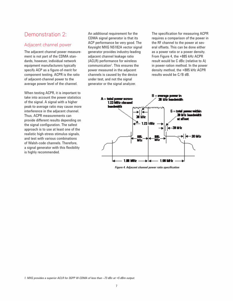
Adjacent channel powerThe adjacent channel power measure-ment is not part of the CDMA stan-dards, however, individual network equipment manufacturers typically specify ACP as a figure-of-merit for component testing. ACPR is the ratio of adjacent-channel power to the average power level of the channel.
When testing ACPR, it is important to take into account the power statistics of the signal. A signal with a higher peak-to-average ratio may cause more interference in the adjacent channel. Thus, ACPR measurements can provide different results depending on the signal configuration. The safest approach is to use at least one of the realistic high-stress stimulus signals, and test with various combinations of Walsh-code channels. Therefore, a signal generator with this flexibility is highly recommended.
Figure 4. Adjacent channel power ratio specification
1. MXG provides a superior ACLR for 3GPP W-CDMA of less than –73 dBc at +5 dBm output.
An additional requirement for the CDMA signal generator is that its ACP performance be very good. The Keysight MXG N5182A vector signal generator provides industry-leading adjacent channel leakage ratio (ACLR) performance for wireless communication1. This ensures the power measured in the adjacent channels is caused by the device under test, and not the signal generator or the signal analyzer.
The specification for measuring ACPR requires a comparison of the power in the RF channel to the power at sev-eral offsets. This can be done either as a power ratio or a power density. From Figure 4, the +885 kHz ACPR result would be C dBc (relative to A) in power-ration method. In the power density method, the +885 kHz ACPR results would be C/B dB.
8
Set up the X-Series analyzer to analyze the CDMA signal.X-Series instructions Keystrokes
Activate (ACP) measurement. [Meas]>{ACP}
Optimize for dynamic range. [Meas setup]>{More}> {Meas Method}>{Integration BW}
Adjust the power level by changingRef Value. [AMPTD]>{Ref Value} [-10] {dBm}
Turn on Noise Correction.
[Meas Setup]>{More 1 of 2}> {Noise Correction On Off}
See Figure 5.
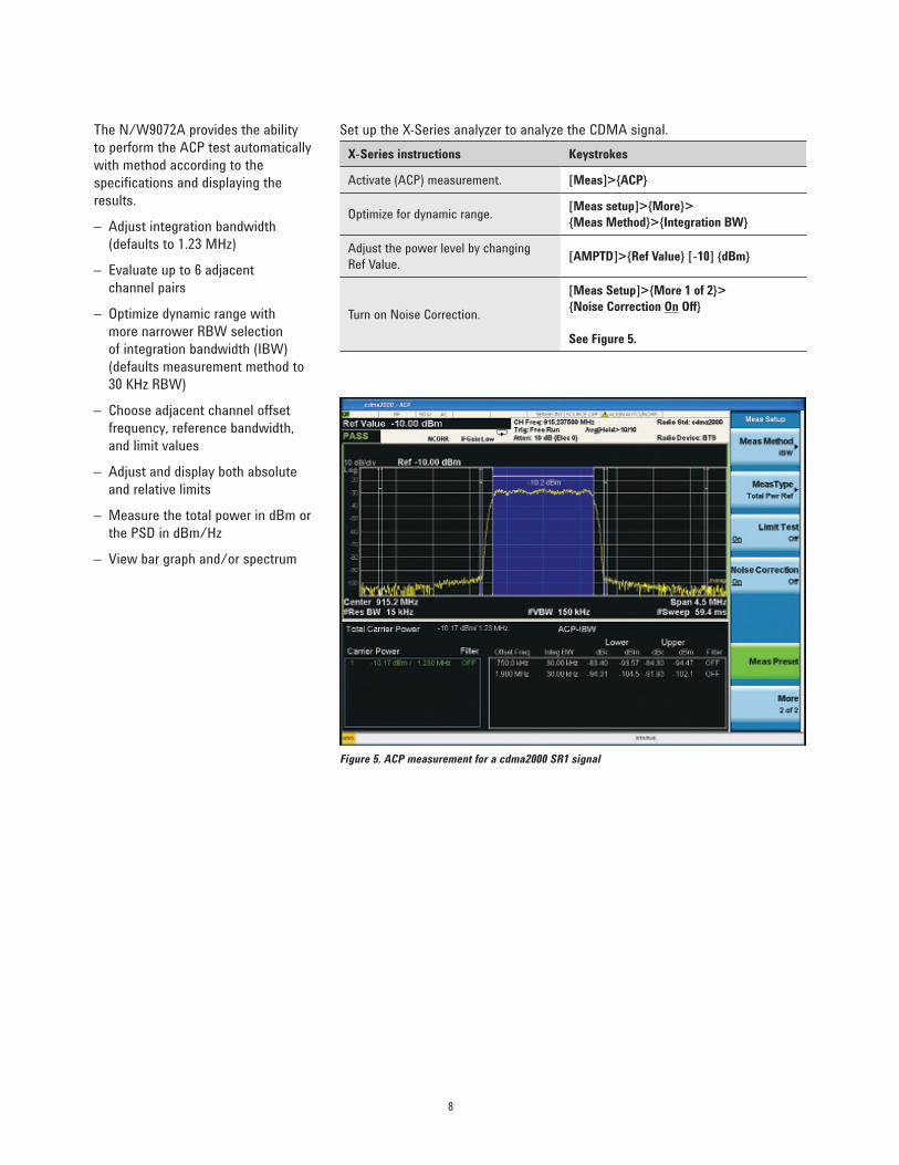
The N/W9072A provides the ability to perform the ACP test automatically with method according to the specifications and displaying the results.
– Adjust integration bandwidth (defaults to 1.23 MHz)
– Evaluate up to 6 adjacent channel pairs
– Optimize dynamic range with more narrower RBW selection of integration bandwidth (IBW) (defaults measurement method to 30 KHz RBW)
– Choose adjacent channel offset frequency, reference bandwidth, and limit values
– Adjust and display both absolute and relative limits
– Measure the total power in dBm or the PSD in dBm/Hz
– View bar graph and/or spectrum
Figure 5. ACP measurement for a cdma2000 SR1 signal

9
Set up the X-Series analyzer to analyze the CDMA signal.X-Series instructions Keystrokes
Active the spectrum emission mask measurement. Observe the mask and trace in the upper window and the table of measured values in the lower window.
[Meas]>{Spectrum Emission Mask}
See Figure 6.
Choose the type of values to display.Observe the measurement values change in the lower window to reflect the selected value type.
[View/Display]>change {Abs Peak Pwr & Freq} to {Rel Peak Pwr & Freq} or {Integrated Power}
View customizable offset and limits.Measurement parameters as well as limit values may be customized for any of the six offset pairs or for any individual offset
[Meas Setup]>{Offset/Limits}>{More}> {Limits}
Figure 6. Spectrum emission mask
Demonstration 3:
Spectrum emission maskThe spectrum emission mask is one of the in-band-of-channel measurements that measures distortion and interference within the system band, but outside of the transmitting channel.
The performance standards recom-mended by the 3GPP2 (refer to C.S0010-D_v2.0, section 4.4.1.3) for cdma2000 have specific limits for transmitted spurious emissions. This measurement has different limits for different frequency offsets measured in different resolution bandwidths. With one-button SEM measurements in N/W9072A, the X-Series signal analyzer makes this measurement very simple versus a traditional spectrum analyzer, which can be tedious and time consuming.
– View table and spectrum formats.
– Measure the total power in dBm or the PSD in dBm/Hz.
– Select the average or peak detector (defaults to average).
– Choose offset frequency, reference bandwidth, and limit values.
– Customize reference channel span, step frequency, and resolution bandwidth.

10
Demonstration 4:
Code domain analysisWalsh codes are the fundamental channelization mechanism for CDMA. Measuring code-domain power is essential for verifying that each code channel is operating at its proper level and to identify problems throughout the transmitter design, from coding to the RF section. System imperfections, such as amplifier non-linearity, will present themselves as an undesired distribution of power in the code domain.
The code domain power provides a quick view of all of the channel elements’ contributions for a given frequency assignment and PN offset. Unlike cdmaOne, in cdma2000 the measurement is complicated by the fact that the Walsh code lengths vary to accommodate the different data rates and SRs of the different RCs.
In the N/W9072A, there are two algorithms that display the code channel power. The Hadamard algo-rithm displays each Walsh code in sequence and uses the Consolidated Marker feature to display the compost representation of the traffic channel. The other is a bit-reverse algorithm that displays the channels as consolidated code spaces.
Generate a cdma2000 forward 12 channel signal in Signal Studio.Signal Studio instructions Keystrokes
Change the carrier of CDMA2000. Forward for new channel configuration.
In the tree view, left pane of the main window, select Carrier 1 under WFM1. In the right pane, click the Channel Configuration, change to 12 Channel Forward from the drop-down menu
Download the signal to the MXG. Press Generate and Download button on the top tool bar.
X-Series instructions Keystrokes
Activate the code domain measurement. [Meas]>{Code Domain}
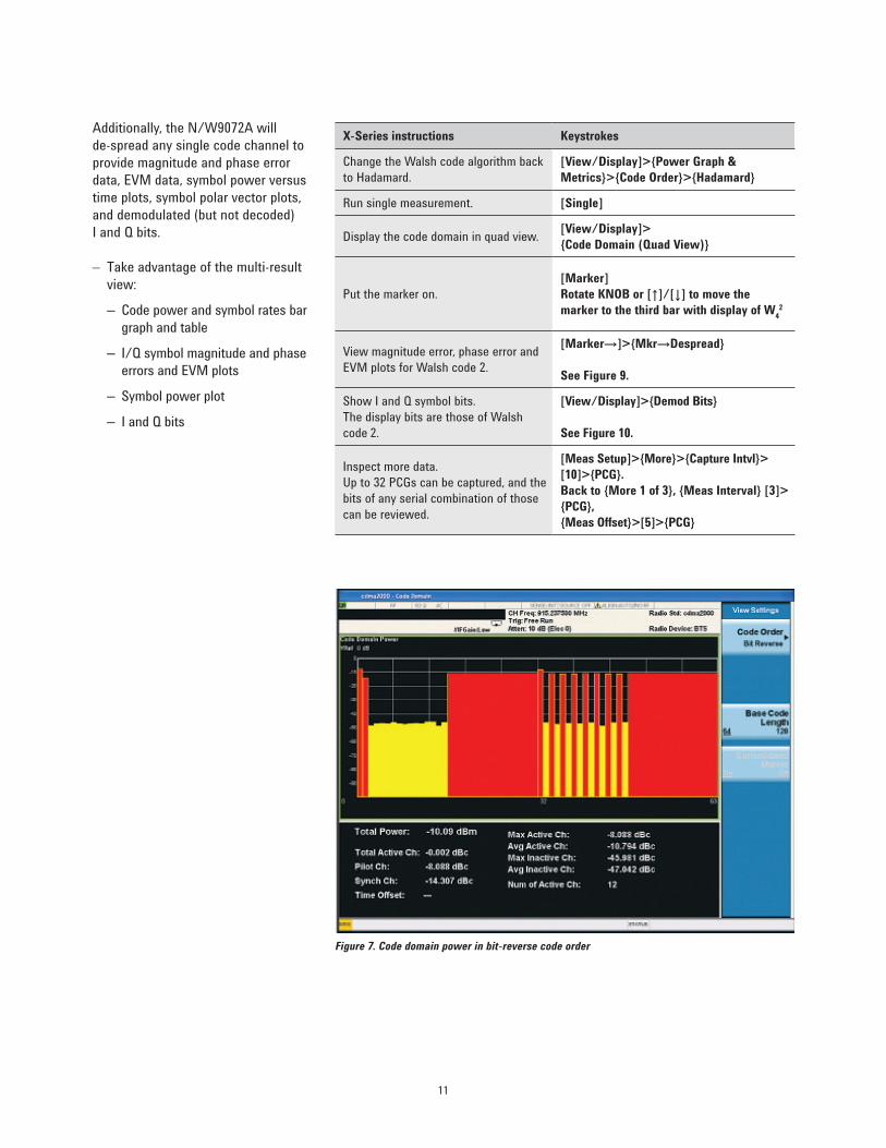
Change the Walsh code algorithm to bit-reverse and examine the new result.
[View/Display]>{Power Graph & Metrics}> {Code Order}>{ Bit Reverse}
See Figure 7.
Use the marker to examine Walsh code. A bar for each channel with height proportionately representative of the channel power and the bar width proportional to the data rate.
[Marker]>[Select Marker 1], rotate KNOB to highlight widest Walsh channel
See Figure 81.
1 The data rate programmed into the MXG will seem different than that measured with the X-Series. In actuality, they are the same. The MXG gives the data rate in bits per second, while the X-Series measures the data rate in symbols per second. The data rates are related through the radio configuration and the spreading rate.
11
Additionally, the N/W9072A will de-spread any single code channel to provide magnitude and phase error data, EVM data, symbol power versus time plots, symbol polar vector plots, and demodulated (but not decoded) I and Q bits.
– Take advantage of the multi-result view:
– Code power and symbol rates bar graph and table
– I/Q symbol magnitude and phase errors and EVM plots
– Symbol power plot
– I and Q bits
X-Series instructions Keystrokes
Change the Walsh code algorithm back to Hadamard.
[View/Display]>{Power Graph & Metrics}>{Code Order}>{Hadamard}
Run single measurement. [Single]
Display the code domain in quad view. [View/Display]> {Code Domain (Quad View)}
Put the marker on. [Marker] Rotate KNOB or [↑]/[↓] to move the marker to the third bar with display of W4
2
View magnitude error, phase error and EVM plots for Walsh code 2.
[Marker→]>{Mkr→Despread}
See Figure 9.
Show I and Q symbol bits. The display bits are those of Walsh code 2.
[View/Display]>{Demod Bits}
See Figure 10.
Inspect more data. Up to 32 PCGs can be captured, and the bits of any serial combination of those can be reviewed.
[Meas Setup]>{More}>{Capture Intvl}> [10]>{PCG}.Back to {More 1 of 3}, {Meas Interval} [3]> {PCG}, {Meas Offset}>[5]>{PCG}
Figure 7. Code domain power in bit-reverse code order

12
Figure 9. Code domain power in quad view
Figure 10. Symbol power and demodulated I/Q bits
Figure 8. Code domain power measurement marker identifies correct code assignment and power level for active Walsh code W4
2

13
Figure 11. Modulation accuracy with cdma2000 forward 12 channel signal
Demonstration 5:
Modulation accuracy (Composite rho) In the CDMA standard, the specified measurement for modulation accu-racy is rho. Rho is the ratio of the correlated power to the total power. The correlated power is computed by removing frequency, phase and time offsets and performing a cross correlation between the corrected signal and an ideal reference.
With N/W9072A, the X-series signal analyzer can help to evaluate the quality of the transmitter for a multichannel signal, detect spreading or scramble errors, identify certain problems between baseband and RF sections, and analyze errors that cause high interference in the signal.
– Measure EVM, rho, and peak code domain error (Pk CDE)
– Customize limits for rms EVM, peak EVM, rho, peak CDE, timing error and phase error
– Specify chip rate and PN offsets
– View I/Q polar constellation and magnitude error, phase error, and EVM plots
– Read power, timing, phase and EVM data for each active channel
– Choose to include or exclude the I/Q origin offset in the EVM calculation
Generate a cdma2000 forward 9 channel signal in the Signal Studio.Signal Studio instructions Keystrokes
Change the filter type to improve EVM.
In the tree view, left pane of the main window, select Carrier 1. In the right pane, click on Filter, pull-down menu of the packet type to choose IS95 EVM EQ
Download the signal to the MXG. Press Generate and Download button on the top tool bar.
Setup the X-Series analyzer to analyze the cdma2000 forward Pilot signal.X-Series instructions Keystrokes
Go to modulation accuracy measurement in a single measurement control.
Observe the I/Q measured polar vector display on the right and the quantitative data provided on the left.
[Meas]>{More 1 of 2}>{Modulation Accuracy (Composite Rho)} Press [Single]
See Figure 11.
Examine limit values menu. [Meas Setup]>{Limits}
View Power, Timing, Phase and CDE by each Walsh code.
[View/Display]>{Power Timing & Phase}
See Figure 12.
Note: Follow the message if “Multi channel Estimator” is not at On.

14
In the 3GPP2 C.S0010, there are two paragraphs (refer to 4.2.1.2, and 4.2.1.3) that specify the timing and phase tests for transmitters. The table in the right shows the detailed descriptions and limitations for these two items.
Figure 12 shows the power, timing, phase and CDE for each active Walsh code.
4.2.1.2 Pilot channel to code channel time tolerance
Measures the time offset or timing error between the pilot (Walsh 0) and each of the other Walsh codes.
Less than 50 nanoseconds
4.2.1.3 Pilot channel to code channel phase tolerance
Measures the phase difference between the pilot channel and each Walsh channel.
Less than 50 milliradians or 2.86 degrees
Figure 12. Power, Timing, Phase and CDE by each Walsh code

15
Figure 13. The CCDF curves for two cdma2000 SR1 signals with different channel configurations
Demonstration 6:
Power statistics (CCDF)The complementary cumulative distribution function (CCDF) is a plot of peak-to-average power ratio (PAR) versus probability and it characterizes the power statistics of a signal. CCDF is a key tool for power amplifier design for cdma2000 base station, which is particularly challenging because the amplifier must be capable of handling the high PAR the signal exhibits while maintaining good adjacent channel leakage performance. Designing multicarrier power amplifiers pushes complexity yet another step farther.
In cdma2000, as in cdmaOne, the power statistics of the signal depend on channel configuration, modulation, filtering, clipping level, and other factors. In general, the peak-to- average power ratio increases as more channels are activated.
– Customize information bandwidth (defaults to 1.5 MHz)
– Specify measurement interval
– Set a reference trace or compare to Gaussian noise trace
– Take advantage of the 0.01 dB histogram resolution
Set up the X-Series analyzer to analyze the CDMA signal.X-Series instructions Keystrokes
Active the CCDF. [Meas]>{More 1 of 2}>{Power Stat CCDF}
Set the 9 channel signal trace as a reference.
[Trace/Detector]>{Store Ref Trace}, then select {Ref Trace On}
[Single]
Send another 4 channel signal into the MXA. Measure its CCDF again.
[Restart]
See Figure 13.In general, the peak-to-average power ratio increases as more channels are activated.
9-channel signalAWGN Reference4-channel signal
0.1% PTA ratio values for 4-channel
16
Demonstration 7:
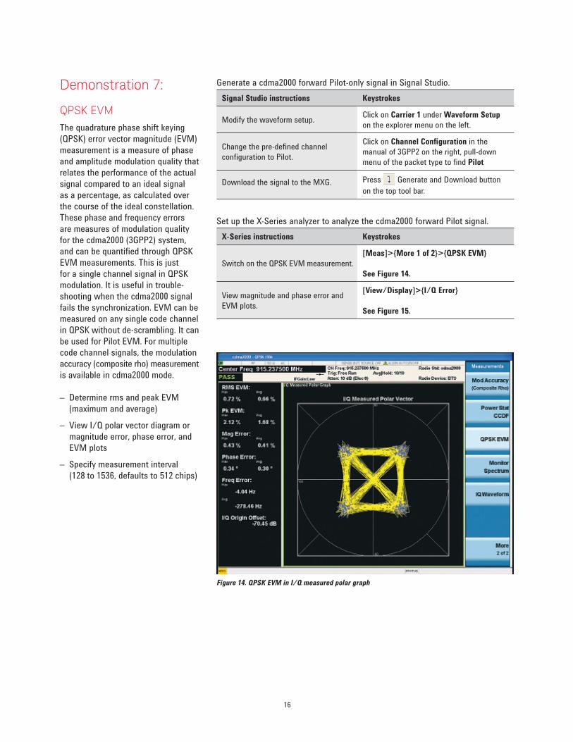
QPSK EVMThe quadrature phase shift keying (QPSK) error vector magnitude (EVM) measurement is a measure of phase and amplitude modulation quality that relates the performance of the actual signal compared to an ideal signal as a percentage, as calculated over the course of the ideal constellation. These phase and frequency errors are measures of modulation quality for the cdma2000 (3GPP2) system, and can be quantified through QPSK EVM measurements. This is just for a single channel signal in QPSK modulation. It is useful in trouble-shooting when the cdma2000 signal fails the synchronization. EVM can be measured on any single code channel in QPSK without de-scrambling. It can be used for Pilot EVM. For multiple code channel signals, the modulation accuracy (composite rho) measurement is available in cdma2000 mode.
– Determine rms and peak EVM (maximum and average)
– View I/Q polar vector diagram or magnitude error, phase error, and EVM plots
– Specify measurement interval (128 to 1536, defaults to 512 chips)
Generate a cdma2000 forward Pilot-only signal in Signal Studio.Signal Studio instructions Keystrokes
Modify the waveform setup. Click on Carrier 1 under Waveform Setup on the explorer menu on the left.
Change the pre-defined channel configuration to Pilot.
Click on Channel Configuration in the manual of 3GPP2 on the right, pull-down menu of the packet type to find Pilot
Download the signal to the MXG. Press Generate and Download button on the top tool bar.
Set up the X-Series analyzer to analyze the cdma2000 forward Pilot signal.X-Series instructions Keystrokes
Switch on the QPSK EVM measurement.[Meas]>{More 1 of 2}>{QPSK EVM}
See Figure 14.
View magnitude and phase error and EVM plots.
[View/Display]>{I/Q Error}
See Figure 15.
Figure 14. QPSK EVM in I/Q measured polar graph

17
Figure 15. QPSK EVM in I/Q error quad view
Related LiteratureKeysight AN1311 Understanding CDMA Measurements for Base Stations and Their Components, Literature Number 5968-0953E
Designing and Testing cdma2000 Base Stations (Application Note 1357), Literature Number 5980-1303E
PSA Series Spectrum analyzers E4406A Vector Signal Analyzer cdma2000 and 1xEV-DV Measurement Personalities, Literature Number 5988-3694EN
Product Web SitesN/W9072A cdma2000/cdmaOne: www.keysight.com/find/n9072a and www.keysight.com/find/w9072a
X-Series signal analyzers: www.keysight.com/find/X-Series
X-Series advanced measurement applications: www.keysight.com/find/X-Series_Apps
Signal Studio software: www.keysight.com/find/SignalStudio
Signal generators: www.keysight.com/find/sg
18 | Keysight | Keysight N9072 & W9072A cdma2000/cdmaOne X-Series Measurement Application - Demo Guide
This information is subject to change without notice.© Keysight Technologies, 2011-2014Published in USA, August 1, 20145990-8011ENwww.keysight.com
myKeysight
www.keysight.com/find/mykeysightA personalized view into the information most relevant to you.
www.lxistandard.orgLAN eXtensions for Instruments puts the power of Ethernet and the Web inside your test systems. Keysight is a founding member of the LXI consortium.
www.keysight.com/find/ThreeYearWarrantyKeysight’s commitment to superior product quality and lower total cost of ownership. The only test and measurement company with three-year warranty standard on all instruments, worldwide.
Keysight Assurance Planswww.keysight.com/find/AssurancePlansUp to five years of protection and no budgetary surprises to ensure your instruments are operating to specification so you can rely on accurate measurements.
www.keysight.com/qualityKeysight Electronic Measurement GroupDEKRA Certified ISO 9001:2008 Quality Management System
Keysight Channel Partnerswww.keysight.com/find/channelpartnersGet the best of both worlds: Keysight’s measurement expertise and product breadth, combined with channel partner convenience.
cdma2000 is a US registered certification mark of the Telecommunications Industry Association
For more information on Keysight Technologies’ products, applications or services, please contact your local Keysight office. The complete list is available at:www.keysight.com/find/contactus
Americas Canada (877) 894 4414Brazil 55 11 3351 7010Mexico 001 800 254 2440United States (800) 829 4444
Asia PacificAustralia 1 800 629 485China 800 810 0189Hong Kong 800 938 693India 1 800 112 929Japan 0120 (421) 345Korea 080 769 0800Malaysia 1 800 888 848Singapore 1 800 375 8100Taiwan 0800 047 866Other AP Countries (65) 6375 8100
Europe & Middle EastAustria 0800 001122Belgium 0800 58580Finland 0800 523252France 0805 980333Germany 0800 6270999Ireland 1800 832700Israel 1 809 343051Italy 800 599100Luxembourg +32 800 58580Netherlands 0800 0233200Russia 8800 5009286Spain 0800 000154Sweden 0200 882255Switzerland 0800 805353
Opt. 1 (DE)Opt. 2 (FR)Opt. 3 (IT)
United Kingdom 0800 0260637
For other unlisted countries:www.keysight.com/find/contactus(BP-05-19-14)