keysight u1461a insulation multimeter/ u1453a...
TRANSCRIPT
Keysight U1461A Insulation Multimeter/U1453A Insulation Tester
User’s Guide

2 U1461A/U1453A User’s Guide
NoticesCopyright Notice© Keysight Technologies 2014–2016No part of this manual may be reproduced in any form or by any means (including electronic storage and retrieval or translation into a foreign language) without prior agreement and written consent from Keysight Technologies as governed by United States and international copyright laws.
Manual Part NumberU1461-90003
EditionEdition 9, November 18, 2016
Printed in:Printed in Malaysia
Published by:Keysight TechnologiesBayan Lepas Free Industrial Zone,11900 Penang, Malaysia
Technology Licenses The hardware and/or software described in this document are furnished under a license and may be used or copied only in accordance with the terms of such license.
Declaration of ConformityDeclarations of Conformity for this product and for other Keysight products may be downloaded from the Web. Go to http://www.keysight.com/go/conformity. You can then search by product number to find the latest Declaration of Conformity.
U.S. Government RightsThe Software is “commercial computer software,” as defined by Federal Acquisition Regulation (“FAR”) 2.101. Pursuant to FAR 12.212 and 27.405-3 and Department of Defense FAR Supplement (“DFARS”) 227.7202, the U.S. government acquires commercial computer software under the same terms by which the software is customarily provided to the public. Accordingly, Keysight provides the Software to U.S. government customers under its standard commercial license, which is embodied in its End User License Agreement (EULA), a copy of which can be found at http://www.keysight.com/find/sweula. The license set forth in the EULA represents the exclusive authority by which the U.S. government may use, modify, distribute, or disclose the Software. The EULA and the license set forth therein, does not require or permit, among other things, that Keysight: (1) Furnish technical information related to commercial computer software or commercial computer software documentation that is not customarily provided to the public; or (2) Relinquish to, or otherwise provide, the government rights in excess of these rights customarily provided to the public to use, modify, reproduce, release, perform, display, or disclose commercial computer software or commercial computer software documentation. No additional government requirements beyond those set forth in the EULA shall apply, except to the extent that those terms, rights, or licenses are explicitly required from all providers of commercial computer software pursuant to the FAR and the DFARS and are set forth specifically in writing elsewhere in the EULA. Keysight shall be under no obligation to update, revise or otherwise modify the Software. With respect to any technical data as defined by FAR 2.101, pursuant to FAR 12.211 and 27.404.2 and DFARS 227.7102, the U.S. government acquires no greater than Limited Rights as defined in FAR 27.401 or DFAR 227.7103-5 (c), as applicable in any technical data.
WarrantyTHE MATERIAL CONTAINED IN THIS DOCUMENT IS PROVIDED “AS IS,” AND IS SUBJECT TO BEING CHANGED, WITHOUT NOTICE, IN FUTURE EDITIONS. FURTHER, TO THE MAXIMUM EXTENT PERMITTED BY APPLICABLE LAW, KEYSIGHT DISCLAIMS ALL WARRANTIES, EITHER EXPRESS OR IMPLIED, WITH REGARD TO THIS MANUAL AND ANY INFORMATION CONTAINED HEREIN, INCLUDING BUT NOT LIMITED TO THE IMPLIED WARRANTIES OF MERCHANTABILITY AND FITNESS FOR A PARTICULAR PURPOSE. KEYSIGHT SHALL NOT BE LIABLE FOR ERRORS OR FOR INCIDENTAL OR CONSEQUENTIAL DAMAGES IN CONNECTION WITH THE FURNISHING, USE, OR PERFORMANCE OF THIS DOCUMENT OR OF ANY INFORMATION CONTAINED HEREIN. SHOULD KEYSIGHT AND THE USER HAVE A SEPARATE WRITTEN AGREEMENT WITH WARRANTY TERMS COVERING THE MATERIAL IN THIS DOCUMENT THAT CONFLICT WITH THESE TERMS, THE WARRANTY TERMS IN THE SEPARATE AGREEMENT SHALL CONTROL.
Safety Information
CAUTIONA CAUTION notice denotes a hazard. It calls attention to an operating procedure, practice, or the like that, if not correctly performed or adhered to, could result in damage to the product or loss of important data. Do not proceed beyond a CAUTION notice until the indicated conditions are fully understood and met.
WARNINGA WARNING notice denotes a hazard. It calls attention to an operating procedure, practice, or the like that, if not correctly performed or adhered to, could result in personal injury or death. Do not proceed beyond a WARNING notice until the indicated conditions are fully understood and met.

Safety Symbols
The following symbols on the instrument and in the documentation indicate precautions which must be taken to maintain safe operation of the instrument.
Direct current (DC) Caution, risk of electric shock
Alternating current (AC)Caution, risk of danger (refer to this manual for specific Warning or Caution information)
Both direct and alternating currentCategory III 1000 V overvoltage protection
Earth (ground) terminalCategory IV 600 V overvoltage protection
Equipment protected throughout by double insulation or reinforced insulation
Do not use in distribution systems with voltages higher than 600 V
CAT III1000 V
CAT IV600 V
U1461A/U1453A User’s Guide 3

Safety Considerations
Read the information below before using this tester. The descriptions and instructions in this manual apply to the Keysight U1461A Insulation Multimeter and the U1453A Insulation Tester.
Model U1461A appears in all illustrations. The word tester is used to represent both models.
WARNING– Do not exceed any of the measurement limits defined in the specifications
to avoid instrument damage and the risk of electric shock.
– Do not use the tester if it is damaged. Before you use the tester, inspect the case. Look for cracks or missing plastic. Pay particular attention to the insulation surrounding the connectors.
– Inspect the test leads for damaged insulation or exposed metal. Check the test leads for continuity. Replace damaged test leads before you use the tester.
– Do not operate the tester around explosive gas, vapor, or wet environments.
– Do not apply more than the rated voltage (as marked on the tester) between terminals, or between terminal and earth ground.
– Before use, verify the tester's operation by measuring a known voltage.
– When servicing the tester, use only the specified replacement parts.
– Use caution when working above 60 VDC, 30 VAC RMS, or 42.4 V peak. Such voltages pose a shock hazard.
– When using the probes, keep your fingers behind the finger guards on the probes.
– Connect the common test lead before you connect the live test lead. When you disconnect the leads, disconnect the live test lead first.
– Remove the test leads from the tester before you open the battery cover.
– Do not operate the tester with the battery cover or portions of the cover removed or loosened.
– To avoid false readings, which may lead to possible electric shock or personal injury, replace the battery as soon as the low battery indicator appears and flashes.
4 U1461A/U1453A User’s Guide

WARNING– Ensure that you do not perform insulation resistance tests in distribution
systems with voltages higher than 600 V.
– For insulation resistance tests, ensure that you select a suitable test voltage for the equipment to be tested.
For model U1461A only:
– When measuring current, turn off the circuit power before connecting the tester in the circuit. Remember to place the tester in series with the circuit.
– Be aware of the presence of hazardous voltage before using the Low Pass Filter (LPF) function for voltage measurement. Voltages measured are usually greater than the values indicated on the tester as the voltages with higher frequencies have been filtered through the LPF function.
CAUTION– Disconnect circuit power and discharge all high-voltage capacitors
before testing resistance, continuity, diodes, or capacitance.
– Use the proper terminals, function, and range for your measurements.
– This device is for use at altitudes of up to 2,000 m.
– Always use the specified battery type. The power for the tester is supplied with four 1.5 V AA batteries. Observe the correct polarity markings before you insert the batteries to ensure proper insertion of the batteries in the tester.
For model U1461A only:
– Never measure voltage when current measurement is selected.
U1461A/U1453A User’s Guide 5

6 U1461A/U1453A User’s Guide
Measurement Category
The Keysight U1461A/U1453A tester has a safety rating of CAT III, 1000 V and CAT IV, 600 V.
Measurement CAT I Measurements performed on circuits not directly connected to the AC mains. Examples are measurements on circuits not derived from the AC mains and specially protected (internal) mains-derived circuits.
Measurement CAT II Measurements performed on circuits directly connected to a low-voltage installation. Examples are measurements on household appliances, portable tools, and similar equipment.
Measurement CAT III Measurements performed in the building installation. Examples are measurements on distribution boards, circuit- breakers, wiring, including cables, bus-bars, junction boxes, switches, socket outlets in the fixed installation, and equipment for industrial use, and some other equipment including stationary motors with permanent connection to the fixed installation.
Measurement CAT IV Measurements performed at the source of the low-voltage installation. Examples are electricity meters and measurements on primary overcurrent protection devices and ripple control units.
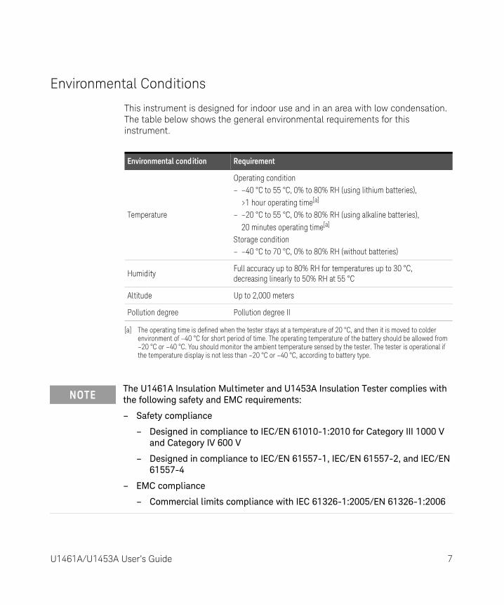
Environmental Conditions
This instrument is designed for indoor use and in an area with low condensation. The table below shows the general environmental requirements for this instrument.
Environmental cond ition Requirement
Temperature
Operating condition– –40 °C to 55 °C, 0% to 80% RH (using lithium batteries),
>1 hour operating time[a]
– –20 °C to 55 °C, 0% to 80% RH (using alkaline batteries),
20 minutes operating time[a]
Storage condition– –40 °C to 70 °C, 0% to 80% RH (without batteries)
[a] The operating time is defined when the tester stays at a temperature of 20 °C, and then it is moved to colder environment of –40 °C for short period of time. The operating temperature of the battery should be allowed from –20 °C or –40 °C. You should monitor the ambient temperature sensed by the tester. The tester is operational if the temperature display is not less than –20 °C or –40 °C, according to battery type.
HumidityFull accuracy up to 80% RH for temperatures up to 30 °C, decreasing linearly to 50% RH at 55 °C
Altitude Up to 2,000 meters
Pollution degree Pollution degree II
NOTEThe U1461A Insulation Multimeter and U1453A Insulation Tester complies with the following safety and EMC requirements:
– Safety compliance
– Designed in compliance to IEC/EN 61010-1:2010 for Category III 1000 V and Category IV 600 V
– Designed in compliance to IEC/EN 61557-1, IEC/EN 61557-2, and IEC/EN 61557-4
– EMC compliance
– Commercial limits compliance with IEC 61326-1:2005/EN 61326-1:2006
U1461A/U1453A User’s Guide 7

Regulatory Markings
The CE mark is a registered trademark of the European Community. This CE mark shows that the product complies with all the relevant European Legal Directives.
The RCM mark is a registered trademark of the Spectrum Management Agency of Australia. This signifies compliance with the Australia EMC Framework regulations under the terms of the Radio Communication Act of 1992.
ICES/NMB-001 indicates that this ISM device complies with the Canadian ICES-001.Cet appareil ISM est conforme a la norme NMB-001 du Canada.
This instrument complies with the WEEE Directive (2002/96/EC) marking requirement. This affixed product label indicates that you must not discard this electrical or electronic product in domestic household waste.
The CSA mark is a registered trademark of the Canadian Standards Association.
This symbol indicates the time period during which no hazardous or toxic substance elements are expected to leak or deteriorate during normal use. Forty years is the expected useful life of the product.
8 U1461A/U1453A User’s Guide

Waste Electrical and Electronic Equipment (WEEE) Directive 2002/96/EC
This instrument complies with the WEEE Directive (2002/96/EC) marking requirement. This affixed product label indicates that you must not discard this electrical or electronic product in domestic household waste.
Product category:
With reference to the equipment types in the WEEE directive Annex 1, this instrument is classified as a “Monitoring and Control Instrument” product.
The affixed product label is as shown below.
Do not dispose in domestic household waste.
To return this unwanted instrument, contact your nearest Keysight Service Center, or visit http://about.keysight.com/en/companyinfo/environment/takeback.shtml for more information.
Sales and Technical Support
To contact Keysight for sales and technical support, refer to the support links on the following Keysight websites:
– www.keysight.com/find/insulationtesters (product-specific information and support, software and documentation updates)
– www.keysight.com/find/assist(worldwide contact information for repair and service)
U1461A/U1453A User’s Guide 9

THIS PAGE HAS BEEN INTENTIONALLY LEFT BLANK.
10 U1461A/U1453A User’s Guide

Table of Contents
Safety Symbols . . . . . . . . . . . . . . . . . . . . . . . . . . . . . . . . . . . . . . . . . . . . .3Safety Considerations . . . . . . . . . . . . . . . . . . . . . . . . . . . . . . . . . . . . . . . .4Measurement Category . . . . . . . . . . . . . . . . . . . . . . . . . . . . . . . . . . . . . .6Environmental Conditions . . . . . . . . . . . . . . . . . . . . . . . . . . . . . . . . . . . .7Regulatory Markings . . . . . . . . . . . . . . . . . . . . . . . . . . . . . . . . . . . . . . . . .8Waste Electrical and Electronic Equipment (WEEE) Directive
2002/96/EC . . . . . . . . . . . . . . . . . . . . . . . . . . . . . . . . . . . . . . . . . . . . .9Product category: . . . . . . . . . . . . . . . . . . . . . . . . . . . . . . . . . . . . . . . .9
Sales and Technical Support . . . . . . . . . . . . . . . . . . . . . . . . . . . . . . . . . .9
1 Introduction
About This Manual . . . . . . . . . . . . . . . . . . . . . . . . . . . . . . . . . . . . . . . . .20Documentation map . . . . . . . . . . . . . . . . . . . . . . . . . . . . . . . . . . . . .20Safety notes . . . . . . . . . . . . . . . . . . . . . . . . . . . . . . . . . . . . . . . . . . . .20
Preparing Your Tester . . . . . . . . . . . . . . . . . . . . . . . . . . . . . . . . . . . . . . .21Check the shipment . . . . . . . . . . . . . . . . . . . . . . . . . . . . . . . . . . . . . .21Install or change the batteries . . . . . . . . . . . . . . . . . . . . . . . . . . . . . .21Turn on your tester . . . . . . . . . . . . . . . . . . . . . . . . . . . . . . . . . . . . . .24Select the range . . . . . . . . . . . . . . . . . . . . . . . . . . . . . . . . . . . . . . . . .24Adjust the tilt stand . . . . . . . . . . . . . . . . . . . . . . . . . . . . . . . . . . . . . .25Connect to the Handheld Meter Logger Software . . . . . . . . . . . . . .26Connect the Bluetooth adapter . . . . . . . . . . . . . . . . . . . . . . . . . . . . .27
Your Tester in Brief . . . . . . . . . . . . . . . . . . . . . . . . . . . . . . . . . . . . . . . . .28Dimensions . . . . . . . . . . . . . . . . . . . . . . . . . . . . . . . . . . . . . . . . . . . . .28Overview . . . . . . . . . . . . . . . . . . . . . . . . . . . . . . . . . . . . . . . . . . . . . . .30Rotary switch . . . . . . . . . . . . . . . . . . . . . . . . . . . . . . . . . . . . . . . . . . .32Keypad . . . . . . . . . . . . . . . . . . . . . . . . . . . . . . . . . . . . . . . . . . . . . . . .35Display screen . . . . . . . . . . . . . . . . . . . . . . . . . . . . . . . . . . . . . . . . . .39Input terminals . . . . . . . . . . . . . . . . . . . . . . . . . . . . . . . . . . . . . . . . . .47
Cleaning Your Tester . . . . . . . . . . . . . . . . . . . . . . . . . . . . . . . . . . . . . . .48Additional Features . . . . . . . . . . . . . . . . . . . . . . . . . . . . . . . . . . . . . . . . .49
U1461A/U1453A User’s Guide 11
Automatic power-off . . . . . . . . . . . . . . . . . . . . . . . . . . . . . . . . . . . . . 49OLED Auto Dim function . . . . . . . . . . . . . . . . . . . . . . . . . . . . . . . . . . 49Change the OLED brightness . . . . . . . . . . . . . . . . . . . . . . . . . . . . . . 49Hazardous voltage indication . . . . . . . . . . . . . . . . . . . . . . . . . . . . . . 50Power-on options . . . . . . . . . . . . . . . . . . . . . . . . . . . . . . . . . . . . . . . 50
2 Making Measurements
Insulation Resistance Test . . . . . . . . . . . . . . . . . . . . . . . . . . . . . . . . . . . 52Using the Remote Switch Probe . . . . . . . . . . . . . . . . . . . . . . . . . . . . 54Locking the test . . . . . . . . . . . . . . . . . . . . . . . . . . . . . . . . . . . . . . . . . 55Timed (T) insulation resistance/earth-bond resistance test . . . . . . 56Measuring the Dielectric Absorption Ratio (DAR) . . . . . . . . . . . . . . 57Measuring the Polarization Index (PI) . . . . . . . . . . . . . . . . . . . . . . . . 58Viewing the leakage current . . . . . . . . . . . . . . . . . . . . . . . . . . . . . . . 59Performing leakage current trip tests . . . . . . . . . . . . . . . . . . . . . . . . 59Performing stepped voltage trip tests . . . . . . . . . . . . . . . . . . . . . . . 61Changing the insulation resistance test voltage . . . . . . . . . . . . . . . 66
Earth-Bond Resistance Test . . . . . . . . . . . . . . . . . . . . . . . . . . . . . . . . . 67Measuring AC or DC Voltage . . . . . . . . . . . . . . . . . . . . . . . . . . . . . . . . . 70
Auto AC or DC signal identification . . . . . . . . . . . . . . . . . . . . . . . . . 72Using the LPF (Low Pass Filter) feature for AC signals . . . . . . . . . . 73Enabling the LPF in the Setup . . . . . . . . . . . . . . . . . . . . . . . . . . . . . 75
Measuring AC or DC Current . . . . . . . . . . . . . . . . . . . . . . . . . . . . . . . . . 76% Scale of 4-20 mA or 0-20 mA . . . . . . . . . . . . . . . . . . . . . . . . . . . . 78
Measuring Frequency . . . . . . . . . . . . . . . . . . . . . . . . . . . . . . . . . . . . . . . 79Measuring duty cycle and pulse width . . . . . . . . . . . . . . . . . . . . . . . 81
Measuring Resistance . . . . . . . . . . . . . . . . . . . . . . . . . . . . . . . . . . . . . . 82Continuity Test . . . . . . . . . . . . . . . . . . . . . . . . . . . . . . . . . . . . . . . . . . . . 84Diode Test . . . . . . . . . . . . . . . . . . . . . . . . . . . . . . . . . . . . . . . . . . . . . . . . 86
Using the Auto-diode feature . . . . . . . . . . . . . . . . . . . . . . . . . . . . . . 89Measuring Capacitance . . . . . . . . . . . . . . . . . . . . . . . . . . . . . . . . . . . . . 91
Viewing the cable length value . . . . . . . . . . . . . . . . . . . . . . . . . . . . . 93Measuring Temperature . . . . . . . . . . . . . . . . . . . . . . . . . . . . . . . . . . . . . 94
12 U1461A/U1453A User’s Guide

3 Tester Features
Non-Contact AC Voltage Detection (Vsense) . . . . . . . . . . . . . . . . . . .100Making Relative Measurements (Null) . . . . . . . . . . . . . . . . . . . . . . . . .102Capturing Maximum and Minimum Values (Max Min) . . . . . . . . . . . . .103Freezing the Display (TrigHold and AutoHold) . . . . . . . . . . . . . . . . . .105Performing Limit Comparisons (Limit) . . . . . . . . . . . . . . . . . . . . . . . . .106Recording Measurement Data (Log) . . . . . . . . . . . . . . . . . . . . . . . . . .108
Performing manual logs (HAND) . . . . . . . . . . . . . . . . . . . . . . . . . . .109Performing interval logs (AUTO) . . . . . . . . . . . . . . . . . . . . . . . . . . .109Performing event logs (TRIG) . . . . . . . . . . . . . . . . . . . . . . . . . . . . .110
Reviewing Previously Recorded Data (View) . . . . . . . . . . . . . . . . . . . .113
4 Setup Options
Using the Setup Menu . . . . . . . . . . . . . . . . . . . . . . . . . . . . . . . . . . . . .116Editing numerical values . . . . . . . . . . . . . . . . . . . . . . . . . . . . . . . . .117
Setup Menu Summary . . . . . . . . . . . . . . . . . . . . . . . . . . . . . . . . . . . . .118Setup Menu Items . . . . . . . . . . . . . . . . . . . . . . . . . . . . . . . . . . . . . . . . .125
Menu 1 . . . . . . . . . . . . . . . . . . . . . . . . . . . . . . . . . . . . . . . . . . . . . . .125Menu 2 . . . . . . . . . . . . . . . . . . . . . . . . . . . . . . . . . . . . . . . . . . . . . . .129Menu 3 . . . . . . . . . . . . . . . . . . . . . . . . . . . . . . . . . . . . . . . . . . . . . . .131Menu 4 . . . . . . . . . . . . . . . . . . . . . . . . . . . . . . . . . . . . . . . . . . . . . . .135Menu 5 . . . . . . . . . . . . . . . . . . . . . . . . . . . . . . . . . . . . . . . . . . . . . . .139Menu 6 . . . . . . . . . . . . . . . . . . . . . . . . . . . . . . . . . . . . . . . . . . . . . . .141Menu 7 . . . . . . . . . . . . . . . . . . . . . . . . . . . . . . . . . . . . . . . . . . . . . . .145Menu 8 . . . . . . . . . . . . . . . . . . . . . . . . . . . . . . . . . . . . . . . . . . . . . . .149Menu 9 . . . . . . . . . . . . . . . . . . . . . . . . . . . . . . . . . . . . . . . . . . . . . . .150Menu 10 . . . . . . . . . . . . . . . . . . . . . . . . . . . . . . . . . . . . . . . . . . . . . .154Menu 11 . . . . . . . . . . . . . . . . . . . . . . . . . . . . . . . . . . . . . . . . . . . . . .158
5 Characteristics and Specifications
U1461A/U1453A User’s Guide 13

THIS PAGE HAS BEEN INTENTIONALLY LEFT BLANK.
14 U1461A/U1453A User’s Guide

List of Figures
Figure 1-1 Keysight Handheld Meter Logger Software . . . . . . . .26Figure 1-2 Bluetooth adapter connection . . . . . . . . . . . . . . . . . . .27Figure 1-3 Width dimensions . . . . . . . . . . . . . . . . . . . . . . . . . . . . .28Figure 1-4 Height and depth dimensions . . . . . . . . . . . . . . . . . . .29Figure 1-5 Display screen allocation example . . . . . . . . . . . . . . . .39Figure 1-6 Analog bar graph example . . . . . . . . . . . . . . . . . . . . . .45Figure 1-7 Connecting the remote switch probe . . . . . . . . . . . . .47Figure 2-1 Insulation resistance test example . . . . . . . . . . . . . . .53Figure 2-2 T operation . . . . . . . . . . . . . . . . . . . . . . . . . . . . . . . . . .56Figure 2-3 DAR operation . . . . . . . . . . . . . . . . . . . . . . . . . . . . . . .57Figure 2-4 PI operation . . . . . . . . . . . . . . . . . . . . . . . . . . . . . . . . .58Figure 2-5 TRIP operation . . . . . . . . . . . . . . . . . . . . . . . . . . . . . . .60Figure 2-6 Scan signal . . . . . . . . . . . . . . . . . . . . . . . . . . . . . . . . . .62Figure 2-7 SCAN TRIP operation . . . . . . . . . . . . . . . . . . . . . . . . . .63Figure 2-8 Ramp signal . . . . . . . . . . . . . . . . . . . . . . . . . . . . . . . . .64Figure 2-9 RAMP TRIP operation . . . . . . . . . . . . . . . . . . . . . . . . . .65Figure 2-10 Earth-bond resistance test example . . . . . . . . . . . . . .68Figure 2-11 AC or DC voltage measurement example . . . . . . . . . .71Figure 2-12 AC voltage with LPF measurement example . . . . . . . .73Figure 2-13 Enabling the low-pass filter . . . . . . . . . . . . . . . . . . . . .75Figure 2-14 AC or DC current measurement example . . . . . . . . . .77Figure 2-15 Definition of frequency . . . . . . . . . . . . . . . . . . . . . . . . .80Figure 2-16 Resistance measurement example . . . . . . . . . . . . . . .83Figure 2-17 Continuity test example . . . . . . . . . . . . . . . . . . . . . . . .85Figure 2-18 Forward-bias diode test example . . . . . . . . . . . . . . . .87Figure 2-19 Reverse-bias diode test example . . . . . . . . . . . . . . . . .88Figure 2-20 Auto-diode operation . . . . . . . . . . . . . . . . . . . . . . . . . .90Figure 2-21 Capacitance measurement example . . . . . . . . . . . . . .92Figure 2-22 Surface temperature measurement example . . . . . . .96Figure 3-1 Detecting AC voltage example . . . . . . . . . . . . . . . . .101
U1461A/U1453A User’s Guide 15

THIS PAGE HAS BEEN INTENTIONALLY LEFT BLANK.
16 U1461A/U1453A User’s Guide

List of Tables
Table 1-1 Front panel part descriptions . . . . . . . . . . . . . . . . . . . .30Table 1-2 Rear panel parts . . . . . . . . . . . . . . . . . . . . . . . . . . . . . .31Table 1-3 U1461A/U1453A rotary switch functions . . . . . . . . . .32Table 1-4 U1461A/U1453A keypad functions . . . . . . . . . . . . . . .35Table 1-5 General annunciators . . . . . . . . . . . . . . . . . . . . . . . . . .40Table 1-6 Measurement units display . . . . . . . . . . . . . . . . . . . . .44Table 1-7 Analog bar graph display counts/bar . . . . . . . . . . . . .46Table 1-8 Terminal connections for different measuring
functions . . . . . . . . . . . . . . . . . . . . . . . . . . . . . . . . .47Table 1-9 Power-on options . . . . . . . . . . . . . . . . . . . . . . . . . . . . .50Table 2-1 Rotary switch position for insulation resistance tests .52Table 2-2 User test voltage range for insulation resistance . . . .66Table 2-3 Earth-bond resistance test position . . . . . . . . . . . . . .67Table 2-4 AC and DC voltage measurement positions . . . . . . . .70Table 2-5 AC and DC current measurement positions . . . . . . . .76Table 2-6 % Scale measurement range . . . . . . . . . . . . . . . . . . . .78Table 2-7 Measurement positions allowing frequency
measurements . . . . . . . . . . . . . . . . . . . . . . . . . . . . .79Table 2-8 Resistance measurement position . . . . . . . . . . . . . . . .82Table 2-9 Continuity test position . . . . . . . . . . . . . . . . . . . . . . . .84Table 2-10 Diode test position . . . . . . . . . . . . . . . . . . . . . . . . . . . .86Table 2-11 Auto-diode voltage thresholds . . . . . . . . . . . . . . . . . .89Table 2-12 Capacitance measurement position . . . . . . . . . . . . . .91Table 2-13 Temperature measurement position . . . . . . . . . . . . . .94Table 3-1 Hi/Lo default settling values . . . . . . . . . . . . . . . . . . .106Table 3-2 Log maximum capacity . . . . . . . . . . . . . . . . . . . . . . .108Table 3-3 Event log trigger conditions . . . . . . . . . . . . . . . . . . . .111Table 4-1 Setup menu key functions . . . . . . . . . . . . . . . . . . . . .116Table 4-2 Setup menu item descriptions . . . . . . . . . . . . . . . . . .118
U1461A/U1453A User’s Guide 17

THIS PAGE HAS BEEN INTENTIONALLY LEFT BLANK.
18 U1461A/U1453A User’s Guide

U1461A Insulation Multimeter/U1453A Insulation TesterUser’s Guide
1 Introduction
About This Manual 20Preparing Your Tester 21Your Tester in Brief 28Cleaning Your Tester 48Additional Features 49
This chapter helps you set up your tester for the first time. An introduction to all the features of the tester is also given.
19

1 Introduction
About This Manual
Documentation map
The following manuals and software related to the U1461A Insulation Multimeter and the U1453A Insulation Tester are available for download. Please visit our website at http://www.keysight.com/find/hhTechLib for the latest version.
Check the manual edition on the first page of each manual.
User’s Guide. This manual.
Quick Start Guide. Printed copy for outdoor use, included with shipment.
Service Guide. Downloadable from http://www.keysight.com/find/hhTechLib
Keysight Handheld Meter Logger Software, Help, and Quick Start Guide. Downloadable from http://www.keysight.com/hhmeterlogger
Safety notes
The following safety notes are used throughout this manual. More pertinent safety notes for using this product are located under the Safety Symbols section.
CAUTIONCaution denotes a hazard. It calls attention to a procedure that, if not correctly performed or adhered to, could result in damage to or destruction of the product. Do not proceed beyond a caution notice until the indicated conditions are fully understood and met.
WARNINGWarning denotes a hazard. It calls attention to a procedure which, if not correctly performed or adhered to, could result in injury or loss of life. Do not proceed beyond a warning note until the indicated conditions are fully understood and met.
20 U1461A/U1453A User’s Guide

Introduction 1
Preparing Your Tester
Check the shipment
When you receive your tester, check the shipment according to the following procedure.
1 Inspect the shipping container for damage. Signs of damage may include a dented or torn shipping container or cushioning material that indicates signs of unusual stress or compacting. Save the packaging material in case the tester needs to be returned.
2 Carefully remove the contents from the shipping container, and verify that the standard accessories and your ordered options are included in the shipment according to the standard shipped items list found in the printed copy of the U1461A/U1453A Quick Start Guide.
3 For any question or problems, refer to the Keysight contact numbers on the back of this manual.
Install or change the batteries
Your tester is powered by four 1.5 V AA lithium batteries (included in the shipment). When you receive your tester, the batteries are not installed.
Use the following procedure to install or change the batteries.
CAUTIONBefore you proceed with the batteries installation, remove all cable connections to the terminals and ensure that the rotary switch is at the position. Use only the battery type specified in the data sheet.
U1461A/U1453A User’s Guide 21

1 Introduction
1 Remove the orange rubber holster. Pull from a top corner and stretch the orange rubber holster off the tester.
2 Loosen and remove the two screws with a suitable Phillips screwdriver as shown on the right.
3 Lift and remove the battery cover as shown on the left.
4 Lift the inner rubber cover to access the battery compartment.
5 Observe the proper battery polarity. The terminal ends of each battery are indicated inside the battery compartment. Insert four 1.5 V AA batteries.
6 Ensure that the inner rubber cover is positioned properly.
7 Replace the battery cover back in its original position and tighten the screws.
8 Finally fit the orange rubber holster back on the tester.
22 U1461A/U1453A User’s Guide

Introduction 1
The battery level indicator in the upper left-hand corner of the display indicates the relative condition of the batteries.
Replace the batteries as soon as possible when the low battery indicator ( ↔ ) flashes.
Battery level indicator
WARNINGTo avoid false readings, which could lead to possible electric shock or personal injury, replace the battery as soon as the low battery indicator appears. Do not discharge the battery by shorting the battery or reversing the battery polarity in any of the batteries.
CAUTIONTo avoid testers being damaged from battery leakage:
– Always remove dead batteries immediately.
– Always remove the batteries and store them separately if the tester is not going to be used for a long period.
U1461A/U1453A User’s Guide 23

1 Introduction
Turn on your tester
To power ON your tester, turn the rotary switch from the position to any other position.
Select the range
The tester’s selected range is always displayed on the right-hand end of the bar graph.
Selected rangeAutoranging indicator
24 U1461A/U1453A User’s Guide

Introduction 1
Pressing changes the tester range (and disables auto-ranging). Each additional presses of (in manual ranging) sets the tester to the next higher range, unless it is already in the highest range, at which point the range switches to the lowest range.
Press and hold to switch the tester to auto-ranging. Auto-ranging is convenient because the tester automatically selects an appropriate range for sensing and displaying each measurement.
Adjust the tilt stand
To adjust the tester to a 60° standing position, pull the tilt-stand outward to its maximum reach.
NOTE– Changing the tester range (and disabling auto-ranging) is not allowed for
earth-bond resistance tests and insulation resistance tests.
– The range is fixed for diode tests and temperature measurements.
– In auto-range, the tester selects the lowest range to display the highest available precision (resolution) for the input signal.
– If a reading is greater than maximum available range, OL (overload) is shown on the display — except for earth-bond resistance tests and insulation resistance tests where to indicate maximum reading, > is shown on the display instead.
To PC (host)
IR-USB cable
Pull until maximum reach
U1461A/U1453A User’s Guide 25

1 Introduction
Connect to the Handheld Meter Logger Software
You can use the IR communication link (IR communication port, located at the rear panel) and the Keysight Handheld Meter Logger Software to control your tester remotely, perform data logging operations, and transfer the contents of your tester’s memory to a PC.
Ensure that the Keysight logo on the U1173A IR-USB cable connected to the tester is facing up. Firmly push the IR head into the tester’s IR communication port until it snaps into place.
Refer to the Keysight Handheld Meter Logger Software Help and Quick Start Guide for more information on the IR communication link and the Keysight Handheld Meter Logger Software.
The Keysight Handheld Meter Logger Software and its supporting documents (Quick Start Guide and Help) are available for download from http://www.keysight.com/hhmeterlogger.
Figure 1-1 Keysight Handheld Meter Logger Software
26 U1461A/U1453A User’s Guide

Introduction 1
Connect the Bluetooth adapter
The U1117A Infrared (IR)-to-Bluetooth® adapter allows you to connect the tester wirelessly to any Windows PC, Android device, or iOS device.
The U1117A is compatible with the following application or software:
– Keysight Handheld Meter Logger (for Windows PC)
– Keysight Mobile Meter (for Android or iOS devices)
– Keysight Mobile Logger (for Android or iOS devices)
Snap the optic side of the U1117A to the tester’s IR communication port (see Figure 1-2).
Refer to the Keysight U1117A IR-to-Bluetooth Adapter Operating Instructions (download from http://www.keysight.com/find/U1117A) for more information on how to set up the U1117A to a Windows PC, Android device, or iOS device.
Figure 1-2 Bluetooth adapter connection
Bluetooth adapter
U1461A/U1453A User’s Guide 27

1 Introduction
Your Tester in Brief
Dimensions
Front view
Figure 1-3 Width dimensions
100 mm
28 U1461A/U1453A User’s Guide

Introduction 1
Rear and side view
Figure 1-4 Height and depth dimensions
218 mm
58 mm
U1461A/U1453A User’s Guide 29

1 Introduction
Overview
Front panel
The front panel parts of your tester are described in this section.
1
2
3
4
5
Table 1-1 Front panel part descriptions
Legend Description Learn more on:
1 Vsense detector (model U1461A only)/Red LED indicator page 100
2 Display screen page 39
3 Keypad page 35
4 Rotary switch page 32
5 Input terminals page 47
30 U1461A/U1453A User’s Guide

Introduction 1
Rear panel
The rear panel parts of your tester are described in this section.
1
2
3
4
5
Table 1-2 Rear panel parts
Legend Description Learn more on:
1 IR communication port page 26
2 Test lead/probe holders -
3 Battery access (under the orange rubber holster) page 21
4 Tilt stand page 25
5 Fuse access (under the orange rubber holster) -
U1461A/U1453A User’s Guide 31

1 Introduction
Rotary switch
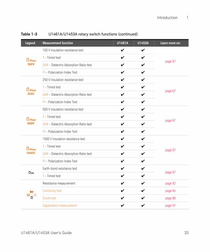
The measurement functions for each rotary switch position are described in Table 1-3. Turning the rotary switch changes the measurement function and resets all other measurement options.
WARNINGRemove the test leads from the measuring source or target before changing the rotary switch position.
NOTE Press to select the alternate measurement function(s) or test methods for insulation resistance tests. See page 35 for more information on the key.
U1461A U1453A
Table 1-3 U1461A/U1453A rotary switch functions
Legend Measurement function U1461A U1453A Learn more on:
50 V Insulation resistance test ✔ ✔
page 67T - Timed test ✔ ✔
DAR - Dielectric Absorption Ratio test ✔ ✔
PI - Polarization Index Test ✔ ✔
32 U1461A/U1453A User’s Guide
Introduction 1
100 V Insulation resistance test ✔ ✔
page 67T - Timed test ✔ ✔
DAR - Dielectric Absorption Ratio test ✔ ✔
PI - Polarization Index Test ✔ ✔
250 V Insulation resistance test ✔ ✔
page 67T - Timed test ✔ ✔
DAR - Dielectric Absorption Ratio test ✔ ✔
PI - Polarization Index Test ✔ ✔
500 V Insulation resistance test ✔ ✔
page 67T - Timed test ✔ ✔
DAR - Dielectric Absorption Ratio test ✔ ✔
PI - Polarization Index Test ✔ ✔
1000 V Insulation resistance test ✔ ✔
page 67T - Timed test ✔ ✔
DAR - Dielectric Absorption Ratio test ✔ ✔
PI - Polarization Index Test ✔ ✔
Earth-bond resistance test ✔ ✔page 67
T - Timed test ✔ ✔
Resistance measurement ✔ ✔ page 82
Continuity test ✔ ✔ page 84
Diode test ✔ ✔ page 86
Capacitance measurement ✔ ✔ page 91
Table 1-3 U1461A/U1453A rotary switch functions (continued)
Legend Measurement function U1461A U1453A Learn more on:
U1461A/U1453A User’s Guide 33

1 Introduction
AC voltage measurement ✔ ✔ page 52
AC voltage measurement with Low Pass Filter (LPF) ✔ - page 73
Auto voltage measurement ✔ ✔
page 52
DC voltage measurement ✔ ✔
AC voltage measurement ✔ ✔
Auto voltage measurement (mV) ✔ -
DC voltage measurement (mV) ✔ -
AC voltage measurement (mV) ✔ -
Temperature measurement ✔ - page 94
Auto current measurement (μA mA) ✔ -
page 76DC current measurement (mA mA) ✔ -
AC current measurement (mA mA) ✔ -
% Scale of 4-20 mA ✔ -
Table 1-3 U1461A/U1453A rotary switch functions (continued)
Legend Measurement function U1461A U1453A Learn more on:
34 U1461A/U1453A User’s Guide

Introduction 1
Keypad
The operation of each key is explained in Table 1-4 below. Pressing a key enables a function, displays a related symbol, and emits a beep. Turning the rotary switch to another position resets the current operation of the key.
U1461A U1453A
Table 1-4 U1461A/U1453A keypad functions
LegendFunction when pressed for:
Less than 1 second More than 1 second
Insulation Resistance (IR) Test: Initiates an IR test (when the rotary switch is in one of the Ω Mega
positions) as long as is held — the tester sources (outputs) a high voltage and measures insulation resistance and is shown on the display.
Earth-Bond Resistance (EBR) Test: Initiates an EBR test (when the rotary switch is in the Ω EB
position) as long as is held — the tester measures earth-bond resistance and is shown on the display.
Trig Hold: Freezes the present reading in the display (except when the rotary switch is in one of the Ω Mega positions or in the Ω EB position).
– In TrigHold mode, press to manually trigger the holding of the next measured value.
– Press and hold again to exit this mode.
Auto Hold: Automatically freezes the present reading once the reading is stable (except when the rotary switch is in one of the Ω Mega positions or in the Ω EB position).
– In AutoHold mode, the reading is updated automatically once the reading is stable and the count setting is exceeded.
– Press and hold again to exit this mode.
U1461A/U1453A User’s Guide 35

1 Introduction
Lock: Press to lock the insulation test or earth-bond resistance test (when the rotary switch is in the appropriate position).
– Press > to initiate an IR or EBR test. The test remains active until you
press or again to release the lock.
– Press during capacitance measurements to view the cable length of the circuit under test.
View: Press and hold to enter the Log Review menu.
– Press to cycle through the previously recorded manual (VIEW H), interval (VIEW A), or event (VIEW E) logging data.
– Press or to view first or last logged data respectively.
– Press or to scroll through the logged data.
– Press to delete the last logged data.
– Press and hold to clear all the logged data for the selected logging mode.
– Press and hold again to exit this mode.
Hz: Press to display the frequency for voltage or current measurements.
– Model U1461A only: Press again to scroll through the frequency (Hz), pulse width (ms), and duty cycle (%) measurements. This option must first be enabled in the Setup menu (see page 157).
– Press again to disable the frequency display.
Esc: Press in the Setup menu to discard your changes.
Table 1-4 U1461A/U1453A keypad functions (continued)
LegendFunction when pressed for:
Less than 1 second More than 1 second
36 U1461A/U1453A User’s Guide

Introduction 1
Press to switch or cycle between the default and al ternate measurement function(s).
Log: The recording option (HAND, AUTO, or TRIG) must first be selected in the Setup menu (see page 126).– HAND (manual data logging) — Press and
hold to log the present reading into the memory. The display will return to normal after a short while (≈ 1 second). To manually log another reading, press and hold again.
– AUTO (automatic data logging) — Press and hold to enable the automatic data logging mode, where data is logged at the interval defined in the Setup menu (see page 126). Press and hold again to exit this mode.
– TRIG (event data logging) — Press and hold to enable the event data logging mode,
where data is logged each time a triggering condition is satisfied (see page 112). Press and hold again to exit this mode.
T: Configures the tester for a timed test (when the rotary switch is in one of the Ω Mega positions or the Ω EB position).
The test will start when you press .
DAR: Configures the tester for a dielectric absorption ratio test (when the rotary switch is in one of the Ω Mega positions).
The test will start when you press .
PI: Configures the tester for a polarization index test (when the rotary switch is in one of the Ω Mega positions).
The test will start when you press .
Limit: Press to enable the comparison for limit mode.
– Press again to set the comparison value. Use the arrow keys (page 116) to change the value shown and press to save your changes.
– Press and hold to exit this mode.
Max Min: Press and hold to start the Max Min recording.
– Press again to cycle through maximum (REC MAX), minimum (REC MIN), average (REC AVG), and present (REC NOW) readings.
– Press and hold again to exit this mode.– Max Min is disabled when Trip tests are
enabled.
Trip: When the rotary switch is in one of the Ω Mega positions, first press to display the leakage current.
Then, press to cycle through the various Trip tests for insulation resistance measurement.
The test will start when you press .– Trip by leakage current– Trip by stepped voltage (Scan)– Trip by stepped voltage (Ramp)
Table 1-4 U1461A/U1453A keypad functions (continued)
LegendFunction when pressed for:
Less than 1 second More than 1 second
U1461A/U1453A User’s Guide 37

1 Introduction
Range: Press to set a manual range and disable auto-ranging.
– Press again to cycle through each available measurement range.
– Press during temperature measurements to change the temperature measurement unit between Celsius (°C) and Fahrenheit (°F). This option must first be enabled in the Setup menu (see page 155).
Auto: Press and hold to enable auto-ranging.
Auto: Press and hold during diode tests to enable the Auto-diode feature. Press and hold
again to exit this mode.Leak: Press to display the leakage current.
Null: Press to enable the relative function.– The displayed value is saved as a reference to
be subtracted from subsequent measurements.
– Press again to view the stored reference value that has been saved. The display will return to normal after a brief period of time (approx. 3 seconds).
– Pressing while the stored reference value is being displayed will cancel the relative function.
Vsense (model U1461A only): Press and hold to enable the non-contact voltage presence
indicator.
– Press to change the Vsense detector’s sensitivity from HIGH SENSE to LOW SENSE.
– Press and hold again to exit this mode.
: Press to increase or decrease the OLED brightness. This option must first be enabled in the Setup menu (see page 132).
Setup: Press and hold to enter the Setup menu.
– In the Setup menu, press or to navigate through the menu pages. Press or at each menu page to move the cursor to a specific menu item.
– Press to change the value of the selected menu item. Use the arrow keys (page 116) to change the value shown.
– Press again to save your changes, or press to discard your changes.
– Press and hold again to exit the Setup menu.
Table 1-4 U1461A/U1453A keypad functions (continued)
LegendFunction when pressed for:
Less than 1 second More than 1 second
38 U1461A/U1453A User’s Guide

Introduction 1
Display screen
The display annunciators of your tester are described in this section. See also “Measurement units” on page 44 for a list of available measurement signs and notations and “Analog bar graph” on page 45 for a tutorial on the analog bar graph located at the bottom of your display screen.
General display annunciators
The general display annunciators of your tester are described in the Table 1-5.
Figure 1-5 Display screen allocation example
A
B
C
D
E
F
G
H
I
J
K
L
M
N
O
P P1
Q R
S
T
U
VX
Y
E
I
J
K
L1
P
Q
O
P1
R
S
T
U
G
H
A
B
C
D
M
F
E1
U1461A/U1453A User’s Guide 39

1 Introduction
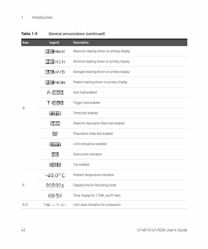
Table 1-5 General annunciators
Area Legend Description
A Battery capacity indication
B APO (Auto Power-Off) enabled
C Remote control enabled
DHazardous voltage sign for measuring voltage ≥30 V or OL (overload)
E
Greater than range (for insulation resistance and earth-bond resistance tests)
Type-J/Type-K thermocouple selected
E1 Polarity (for dual displays)
F
– Capacitor is charging (during capacitance measurement)– Positive slope for pulse width (ms) and duty cycle (%) measurements
– Capacitor is discharging (during capacitance measurement)– Negative slope for pulse width (ms) and duty cycle (%) measurements
Short continuity indication
Open continuity indication
G
Data logging in progress
View mode for reviewing previously logged data
40 U1461A/U1453A User’s Guide

Introduction 1
H Index for AUTO (automatic), HAND (manual), and TRIG (event) data logging
I Analog bar graph
J Scale of analog bar graph
KRelative (Null) enabled
Relative value when Null is enabled
L Primary measurement display (medium)
L1 Primary measurement display (large)
M Comparison result for Limit mode
N Reverse diode indication for Auto-diode test
O Range indication
P Smooth mode enabled
P1 Auto-ranging enabled, Auto-diode enabled, or Auto signal indicator enabled
Table 1-5 General annunciators (continued)
Area Legend Description
U1461A/U1453A User’s Guide 41
1 Introduction
Q
Maximum reading shown on primary display
Minimum reading shown on primary display
Averaged reading shown on primary display
Present reading shown on primary display
Auto hold enabled
Trigger hold enabled
Timed test enabled
Dielectric Absorption Ratio test enabled
Polarization Index test enabled
Limit comparison enabled
Overcurrent indication
Trip enabled
R
Ambient temperature indication
Elapsed time for Recording mode
Timer display for T, DAR, and PI tests
R+S Limit value indication for comparison
Table 1-5 General annunciators (continued)
Area Legend Description
42 U1461A/U1453A User’s Guide

Introduction 1
S
AC, DC, and AC+DC indication for primary display
Low-pass filter enabled for AC measurement
Diode test enabled
Temperature measurement without ambient compensation selected
Test and Test Lock indication for insulation resistance and earth-bond resistance tests
T Measuring units for primary display
U
Test voltage for insulation resistance
% Scale of 4-20 mA or 0-20 mA
Audible continuity test selected
Audible disabled
Tone enabled
V Measuring units for secondary display
Table 1-5 General annunciators (continued)
Area Legend Description
U1461A/U1453A User’s Guide 43

1 Introduction
Measurement units
The available signs and notations for each measurement function in your tester are described in Table 1-6. The units listed below are applicable to the primary display and secondary display measurements of your tester.
X Secondary measurement display
Y AC, DC, and AC+DC indication for secondary display
Table 1-5 General annunciators (continued)
Area Legend Description
Table 1-6 Measurement units display
Sign/Notation Description
T Tera 1E+12 (1000000000000)
G Giga 1E+09 (1000000000)
M Mega 1E+06 (1000000)
k kilo 1E+03 (1000)
n nano 1E–09 (0.000000001)
μ micro 1E–06 (0.000001)
m milli 1E–03 (0.001)
mV, V Voltage, units for voltage measurement
A, mA, μA, nA Ampere, units for current measurement
nF, μF, mF Farad, units for capacitance measurement
Ω, kΩ, MΩ, GΩ, Ohm, units for resistance measurement
kHz, Hz Hertz, units for frequency measurement
ms Millisecond, unit for pulse width measurement
44 U1461A/U1453A User’s Guide

Introduction 1
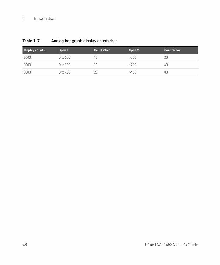
Analog bar graph
The analog bar emulates the needle on an analog tester, without displaying the overshoot.
The “+” or “–” sign indicates whether the measured or calculated value is positive or negative. Each bar represents 10 to 100 counts depending on the display count and range selected.
See Table 1-7 for the relevant display counts, span, and counts per bar.
% Percent, unit for duty cycle measurement
°C Degree Celsius, unit for temperature measurement
°F Degree Fahrenheit, unit for temperature measurement
m, km Meter, units for length
ft Feet, unit for length
s Seconds, unit for Recording mode elapsed time
Table 1-6 Measurement units display (continued)
Sign/Notation Description
NOTEFor frequency, duty cycle, pulse width, 4-20 mA % scale, 0-20 mA % scale, and temperature measurements, the bar graph does not represent the primary display value.
For example, when frequency, duty cycle, or pulse width is displayed on the primary display during voltage or current measurement, the bar graph represents the voltage or current value (not the frequency, duty cycle, or pulse width value). Another example is when 4-20 mA % scale or 0-20 mA % scale is displayed on the primary display, the bar graph represents the current value and not the percentage value.
Figure 1-6 Analog bar graph example
U1461A/U1453A User’s Guide 45
1 Introduction
Table 1-7 Analog bar graph display counts/bar
Display counts Span 1 Counts/bar Span 2 Counts/bar
6000 0 to 200 10 >200 20
1000 0 to 200 10 >200 40
2000 0 to 400 20 >400 80
46 U1461A/U1453A User’s Guide

Introduction 1
Input terminals
The terminal connections for the different measurement functions of your tester are described in the table below.
WARNINGTo avoid damaging this device, do not exceed the input limit.
Table 1-8 Terminal connections for different measuring functions
Rotary switch position Input terminals Overload protection
1000 Vrms
1000 Vrms for short circuit <0.3 A
440 mA/1000 V, 30 kAfast-acting fuse
Figure 1-7 Connecting the remote switch probe
The remote switch probe is used for insulation resistance (IR) and earth-bond resistance (EBR) tests.
Remote switch probe terminal for IR and EBR tests
U1461A/U1453A User’s Guide 47

1 Introduction
Cleaning Your Tester
Dirt or moisture in the terminals can distort readings. Follow the steps below to clean your tester.
1 Turn the tester off, and remove the test leads.
2 Turn the tester over, and shake out any dirt that may have accumulated in the terminals.
Wipe the case with a damp cloth and mild detergent — do not use abrasives or solvents. Wipe the contacts in each terminal with a clean swab dipped in alcohol.
WARNINGTo avoid electrical shock or damage to the tester, ensure that the insides of the casing stay dry at all times.
48 U1461A/U1453A User’s Guide
Introduction 1
Additional Features
Automatic power-off
Your tester automatically turns off if the rotary switch is not moved or a key is not pressed for 10 minutes (default). Pressing any key will turn the tester back on after it is powered off automatically.
To change the timer period or completely disable the automatic power-off, refer to “Changing the auto power-off (APO) timer” on page 132.
OLED Auto Dim function
Your tester’s OLED automatically dims if the rotary switch is not moved or a key is not pressed for 90 seconds (default). This auto dim behavior is enabled by default. Pressing any key or changing the rotary switch position will cancel this effect and reset the auto dim timer.
To disable the auto dim, refer to “Changing the OLED behavior” on page 132.
Change the OLED brightness
If viewing the display becomes difficult in low-light conditions, press to change the OLED brightness (this option must first be enabled in the Setup, see “Changing the OLED behavior” on page 132 for more information.
The LOW, MEDIUM, or HIGH setting must be selected in the tester’s Setup (browse to Menu 3 > BACKLIT) prior to this action. Pressing repeatedly will cycle the OLED brightness from low to medium to high (and back to low again).
You are advised to select an suitable brightness level based on your needs to conserve battery life if you wish to control the OLED brightness level manually.
NOTEThe auto dim function is enabled by default. Refer to “Changing the OLED behavior” on page 132 to disable the auto dim function before you can manually change the OLED brightness.
U1461A/U1453A User’s Guide 49

1 Introduction
Hazardous voltage indication
The tester will display the hazardous voltage ( ) symbol as an early precaution when the measured voltage is equal to or greater than ±DC 30 V or AC 30 V, or when the measured voltage is over the measurement range, OL (overload).
Power-on options
Some options can be selected only while you turn the tester on. These power-on options are listed in the table below. To select a power-on option, press and hold the specified key while turning the rotary switch from the position to any other position. Power-on options remain selected until the tester is turned off.
Table 1-9 Power-on options
Key Description
Displays the power-on greeting. Press any key to exit this mode.
Simulates the Auto Power-Off (APO) mode. Press any key to turn the tester back on and resume normal operation.
Checks firmware version and serial number. The tester’s firmware version and serial number will be shown on the primary display. Press any key to exit this mode.
Toggles the red LED indicator alert for insulation resistance tests. If enabled, the red LED indicator will blink every two seconds during an insulation resistance test. The red LED indicator alert is disabled when the Limit feature (see page 106) is enabled.
Smooth is enabled until the tester is turned off. To permanently enable Smooth, see “Enabling smooth mode” on page 128.
Tests the OLED. All OLED pixels are lighted. Use this mode to verify that there are no dead OLED pixels. Press any key to exit this mode.
50 U1461A/U1453A User’s Guide
U1461A Insulation Multimeter/U1453A Insulation TesterUser’s Guide
2 Making Measurements
Insulation Resistance Test 52Earth-Bond Resistance Test 67Measuring AC or DC Voltage 70Measuring AC or DC Current 76Measuring Frequency 79Measuring Resistance 82Continuity Test 84Diode Test 86Measuring Capacitance 91Measuring Temperature 94
The following sections describe how to take measurements with your tester.
51

2 Making Measurements
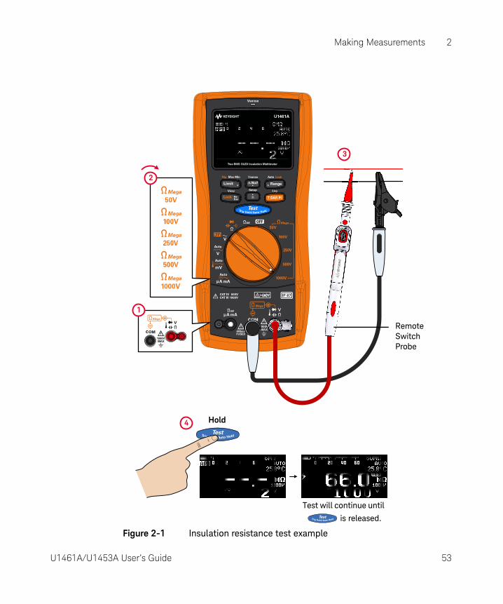
Insulation Resistance Test
Set up your tester as shown in Figure 2-1. Set the rotary switch to a test voltage value that does not exceed the maximum voltage limitation of the circuit under test. Ensure that the device-under-test (DUT) is de-energized before performing any resistance measurement.
Table 2-1 Rotary switch position for insulation resistance tests
Legend Defaul t function Function when is pressed
Rotary switch position
Primary d isplay Secondary d isplay Primary d isplay Secondary d isplay
50 V insulation resistance test
AC+DC V or DC V (during test)
1 Timed (T) test
2 Dielectric Absorption Ratio (DAR) test
3 Polarization Index (PI) test
AC+DC V or DC V (during test)
100 V insulation resistance test
250 V insulation resistance test
500 V insulation resistance test
1000 V insulation resistance test
CAUTION– DO NOT perform insulation resistance test in distribution systems with
voltages higher than 600 V.
– The tester automatically detects if the circuit is energized. If the external voltage is detected to be greater than 30 V (or 50 V or 75 V; depending on
selected option in Setup), the test is inhibited. The symbol is shown on the display when either the external voltage or the test voltage is greater than 30 V. Disconnect the tester and remove the power of the circuit before proceeding.
52 U1461A/U1453A User’s Guide
Making Measurements 2
Figure 2-1 Insulation resistance test example
3
1
2
4
Remote Switch Probe
Hold
Test will continue until
is released.
U1461A/U1453A User’s Guide 53

2 Making Measurements
Using the Remote Switch Probe
The Remote Switch Probe (included in shipment) is used with insulation resistance tests and earth-bond resistance tests, enabling the tester to be controlled remotely from the button on the Remote Switch Probe.
By default the button on the Remote Switch Probe emulates the button on the tester.
To change the default button operation, see “Changing the button operation on the remote switch probe” on page 146.
CAUTIONThe insulation meter will auto-discharge the DUT when the test is complete. However, the DUT will not be auto-discharged when you disconnect the probe before the test is complete. Avoid touching the DUT when the DUT is not fully discharged as it may lead to possible electric shock.
NOTEWhen an insulation test is in progress, the red LED indicator at the top of the tester will blink every 2 seconds (if the Limit function is not enabled). To disable this feature see “Power-on options” on page 50.
54 U1461A/U1453A User’s Guide

Making Measurements 2
Locking the test
You can lock the insulation resistance tests or earth-bond resistance tests temporarily.
Press to enable the lock once feature. The symbol will be shown on the
display. The test will start when you press and it remains active until
or is pressed again.
By default, the tester will reset the locked status when the test is stopped by
pressing or . See “Disabling the lock once feature” on page 147 to disable this feature.
If you disable this feature, you will need to press to unlock the tester, even if the test has already stopped.
2
1
Press once
Press or again to unlock and stop the test.
Lock symbol
U1461A/U1453A User’s Guide 55

2 Making Measurements
Timed (T) insulation resistance/earth-bond resistance test
Use the timed test to obtain measurement results with consistent test times — for later comparisons. Set up your tester as shown in Figure 2-1, and follow the steps shown below.
Figure 2-2 T operation
Press and select the timed test.
Press to start the test.
After 30 seconds.
After 1 minute, time up.
NOTE– Because of the time required to perform the T, PI, and DAR tests, the use of
alligator test clips is recommended.
– The length of the timer is 1 minute by default. To change this value, see “Changing the insulation resistance and earth-bond resistance test period” on page 151 for more information.
56 U1461A/U1453A User’s Guide

Making Measurements 2
Measuring the Dielectric Absorption Ratio (DAR)
Dielectric Absorption Ratio (DAR) is the ratio of the insulation resistance tested at 60 seconds to the insulation resistance tested at 30 seconds. Set up your tester as shown in Figure 2-1, and follow the steps shown below.
Figure 2-3 DAR operation
Press and select the DAR test.
Press to start the test.
After 30 seconds.
After 1 minute, time up.
Press to view t30. Press to view t60.
DAR > 999.9
Error as IR (t1) < 0.001 MΩ
Error as IR (t1) > Maximum Range
After t30.
NOTEYou can change the DAR from 60:30 to 60:15 in the Setup. See “Changing the Dielectric Absorption Ratio (DAR) for insulation resistance tests” on page 148 for more information. Error is shown on the display if the IR is greater than the maximum range or less than 0.001 MΩ after t1/t15/t30; if the test is interrupted by the user; or if the tester’s battery is low.
U1461A/U1453A User’s Guide 57
2 Making Measurements
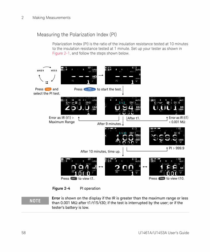
Measuring the Polarization Index (PI)
Polarization Index (PI) is the ratio of the insulation resistance tested at 10 minutes to the insulation resistance tested at 1 minute. Set up your tester as shown in Figure 2-1, and follow the steps shown below.
Figure 2-4 PI operation
Press and select the PI test.
Press to start the test.
After 9 minutes.
After 10 minutes, time up.
Press to view t1. Press to view t10.
PI > 999.9
Error as IR (t1) < 0.001 MΩ
Error as IR (t1) > Maximum Range
After t1.
NOTEError is shown on the display if the IR is greater than the maximum range or less than 0.001 MΩ after t1/t15/t30; if the test is interrupted by the user; or if the tester’s battery is low.
58 U1461A/U1453A User’s Guide

Making Measurements 2
Viewing the leakage current
Press to view the leakage current display. The leakage current display is related to the insulation resistance. The higher the resistance tested, the lower the current is to be measured.
Performing leakage current trip tests
This function may be used to test MOVs (Metal Oxide Varistors), gas discharge tubes, voltage arresters, or sparking gaps. The voltage source will be stopped when the current is greater than the trip current set.
You can select the test voltage and set the current for tripping the test. The trip or breakdown current can be adjusted from 0.001 mA to 1.500 mA from the Setup (see page 153) or by pressing before starting the test.
NOTET/DAR/PI tests, Null, Limit, and test lock is disabled when leakage current trip tests or stepped voltage trip tests are enabled.
U1461A/U1453A User’s Guide 59

2 Making Measurements
Set up your tester as shown in Figure 2-1, and follow the steps shown in Figure 2-5.
Figure 2-5 TRIP operation
Press to view the leakage current, then press
to select the TRIP test.
Press to start the test.
After 1 second.
After 10 seconds, time up. Tripped if measured > value set.
Press to view the TRIP settings. Use
and the arrow keys to change the TRIP settings. Press
to return to the TRIP test.
Press to clear the OC warning.
The tester beeps and the OC symbol blinks continuously.
If no trip occurs, the last current measured
is shown on the primary display.
60 U1461A/U1453A User’s Guide

Making Measurements 2
Performing stepped voltage trip tests
Scan
A typical scan signal length is based on the following parameters:
– IR TEST VOLTAGE - the amplitude end position
– SCAN STEP - the number of steps required to reach the amplitude end position
– SCAN TIME - the dwelling time length for each step
You can configure the scan signal amplitude end position, number of steps (1 to 100 steps), and dwelling time length (1 to 99 seconds) in the Setup (see page 151 and page 152) or by pressing before starting the test.
NOTE– The TRIP test method involves the application of high direct voltage in a
series of uniform voltage steps at regular time intervals. The minimum voltage step is 10 V. Each step should be set to greater than 10 V and the last step is equal to or less than the test voltage setting.
– As an example, if the SCAN STEP is set to 5; for the 1000 V test voltage setting, the test voltage is sent out at the following intervals: 200 V, 400 V, 600 V, 800 V, and 1000 V.
U1461A/U1453A User’s Guide 61

2 Making Measurements
The total dwell time will increase with respect to the number of steps and the scan dwell time per step selected. The scan dwell time is defined as the length of time the scan signal will “dwell” in the present step before incrementing to the next step.
Figure 2-6 Scan signal
Time (t)
Amplitude(V/ A)
Amplitudeend position
Scan dwelling time0
Numberof steps
Total dwelling time
62 U1461A/U1453A User’s Guide

Making Measurements 2
Figure 2-7 SCAN TRIP operation
Press and select the SCAN TRIP test.
Press to start the test.
After 1 second.
After 10 seconds, proceed to next step. Tripped if measured > value set.
Press to view the TRIP settings. Use
and the arrow keys to change the TRIP settings. Press
to return to the TRIP test.
Press to clear the OC warning.
The tester beeps and the OC symbol blinks continuously.
If no trip occurs after the last step, the last current measured is shown on the
primary display.
U1461A/U1453A User’s Guide 63

2 Making Measurements
Ramp
A typical ramp signal length is based on the following parameters:
– IR TEST VOLTAGE - the amplitude end position, and
– RAMP STEP - the number of steps required to reach the amplitude end position.
You can configure the ramp signal amplitude end position and number of steps in the Setup (see page 153) or by pressing before starting the test.
The ramp dwelling time will be set to the fastest of the instrument capability. A higher number of steps provides a more linear ramp signal. This however will result in an increase in the total dwelling time.
A lower number of steps will result in a shorter total dwelling time and a more stepped ramp signal.
NOTEThe principal advantages of the ramped voltage test over the conventional stepped voltage methods are that it gives better control and improved warning of impending failure to avoid damage to the insulation. Elimination of the human variable from the time, voltage, and current parameters yields overall test results which are much more accurate and repeatable.
Figure 2-8 Ramp signal
Time (t)
Amplitude(V)
Amplitudeend position
0
Numberof steps
Total dwelling time
64 U1461A/U1453A User’s Guide

Making Measurements 2
Figure 2-9 RAMP TRIP operation
Press and select the RAMP TRIP test.
Press to start the test.
Next step.
Next step. Tripped if measured > value set.
Press to view the TRIP settings. Use
and the arrow keys to change the TRIP settings. Press
to return to the TRIP test.
Press to clear the OC warning.
The tester beeps and the OC symbol blinks continuously.
If no trip occurs after the last step, the last current
measured is shown on the primary display.
U1461A/U1453A User’s Guide 65

2 Making Measurements
Changing the insulation resistance test voltage
You can adjust the test voltage value of each test voltage position (see Table 2-1) from the Setup menu (Menu 8).
Table 2-2 lists the available range for each test voltage position. See “Changing the insulation resistance test voltage” on page 149 for more information.
Table 2-2 User test voltage range for insulation resistance
Rotary switch position
ParameterRange
F(actory) defaul t Available U(ser) range[a]
IR: 50 V 50 V 10 V to 60 V
IR: 100 V 100 V 10 V to 120 V
IR: 250 V 250 V 10 V to 300 V
IR: 500 V 500 V 10 V to 600 V
IR: 1000 V 1000 V 10 V to 1100 V
[a] Minimum increment of 1 V between each subsequent value.
66 U1461A/U1453A User’s Guide

Making Measurements 2
Earth-Bond Resistance Test
Set up your tester to perform earth-bond resistance tests as shown in Figure 2-10.
Table 2-3 Earth-bond resistance test position
Legend Defaul t function Function when is pressed
Rotary switch position
Primary d isplay Secondary d isplay Primary d isplay Secondary d isplay
Earth-bond resistance test
AC+DC V or DC V (during test)
Timed (T) testAC+DC V or DC V (during test)
CAUTION– To avoid possible damage to your tester or to the equipment under test,
disconnect the circuit power and discharge all high-voltage capacitors before measuring resistance.
– The tester automatically detects if the circuit is energized. If the external voltage is detected to be greater than 2 V, the test is inhibited and
is shown on the display. Disconnect the tester and remove power before proceeding.
NOTE– The earth-bond resistance function is used to measure the resistance
between earth conductors, protective earth conductors, and conductors for equipotential bonding, including their connections and terminals. The function includes an indication of the measured value or indication of limits.
– The voltage source is <6.8 V, and the current is >200 mA when the resistance of ≤2 Ω is to be measured. When the source voltage is <4.7 V, the tester will inhibit the test automatically. The secondary display indicates the voltage (with auto-ranging enabled).
– The APO (auto power-off) function is disabled during the test.
– See also “Timed (T) insulation resistance/earth-bond resistance test” on page 56.
U1461A/U1453A User’s Guide 67

2 Making Measurements
Figure 2-10 Earth-bond resistance test example
3
1
2
4
>
Remote Switch Probe
Hold
Test will continue until
is released.
OR
68 U1461A/U1453A User’s Guide

Making Measurements 2
Using the earth-bond resistance test to verify the fuse condition
1 Keep the test leads open, and ensure that no voltage is applied to the terminals.
2 Press and hold to verify the fuse condition.
3 If the fuse has been blown, FUSE OPEN will be shown on the display. Follow the instructions in the U1461A/U1453A Service Guide to replace the fuse.
Fuse blown; replace fuse.
U1461A/U1453A User’s Guide 69

2 Making Measurements
Measuring AC or DC Voltage
Set up your tester to measure AC or DC voltage as shown in Figure 2-11.
Table 2-4 AC and DC voltage measurement positions
Legend Defaul t function Function when is pressed
Rotary switch position
Primary d isplay Secondary d isplay Primary d isplay Secondary d isplay
AC V - AC V with LPF -
AC V - - -
Auto (V) AC+DC V
Cycles between
1 DC V
2 AC V
3 Auto (V)
1 AC+DC V
2 AC+DC V
3 AC+DC V
Auto (mV) AC+DC mV
Cycles between
1 DC mV
2 AC mV
3 Temperature
4 Auto (mV)
1 AC+DC mV
2 AC+DC mV
3 -, °C, or °F
4 AC+DC mV
NOTE– AC voltage measurements measured with this tester are returned as true
RMS (root mean square) readings. These readings are accurate for sinusoidal waves and other waveforms with no DC offset, such as square waves, triangle waves, and staircase waves.
– This tester displays DC voltage values as well as their polarity. Negative DC voltages will return a negative sign on the left of the display.
– Press to measure the frequency of the voltage source. See “Measuring Frequency” on page 79 to learn more.
70 U1461A/U1453A User’s Guide

Making Measurements 2
Figure 2-11 AC or DC voltage measurement example
AC
3
DC
1
2
U1461A/U1453A User’s Guide 71

2 Making Measurements
Auto AC or DC signal identification
The Auto function is able to automatically identify the signal component (AC or DC) of an electrical source and select a suitable measurement range according to the AC+DC reading.
The Auto function identifies the signal component using the following rules:
– It will consider which component value is greater between the AC or DC.
– The AC value should be greater than a minimum value of 50 counts (based on 6000 counts) of range to prevent residual value due to range changing.
– The frequency measured is greater than 10 Hz for the AC mode.
While the signal is being identified, you can press to lock the (AC or DC) signal on the primary display.
At any time, you can press to stop the Auto function and lock the identified signal component (AC or DC).
The symbol blinks during the identification.
The AC+DC value is shown in the secondary display.
72 U1461A/U1453A User’s Guide

Making Measurements 2
Using the LPF (Low Pass Filter) feature for AC signals
For model U1461A only: Your tester is equipped with an AC low-pass filter to help reduce unwanted electronic noise when measuring AC voltage or AC frequency.
Set up your tester to measure AC voltage as shown in Figure 2-11. Turn the rotary
knob to and press to activate the LPF option. Your tester continues measuring in the chosen AC mode, but now the signal diverts through a filter that blocks unwanted voltages above 1 kHz. Probe the test points, and read the display.
Figure 2-12 AC voltage with LPF measurement example
1
3
AC2
U1461A/U1453A User’s Guide 73

2 Making Measurements
The low-pass filter can improve measurement performance on composite sine waves that are typically generated by inverters and variable frequency motor drives.
WARNING– To avoid possible electric shock or personal injury, do not use the LPF
option to verify the presence of hazardous voltages. Voltages greater than what is indicated may be present. First, make a voltage measurement without the filter to detect the possible presence of hazardous voltages. Then, select the filter option.
– When the LPF option is selected, the measurement function will switch to the manual range mode (defaults to 600 V) for variable speed drive (VSD) applications. It is recommended only to use 600 V and 1000 V in the manual range for VSD testing.
74 U1461A/U1453A User’s Guide

Making Measurements 2
Enabling the LPF in the Setup
You can also enable the low-pass filter to block and attenuate AC signals above 1 kHz for the AC or DC paths of V, mV, and μA mA measurements. See “Enabling the low-pass filter” on page 156 for more information.
Figure 2-13 Enabling the low-pass filter
> >1
2
> > >
Hold
Hold
U1461A/U1453A User’s Guide 75
2 Making Measurements
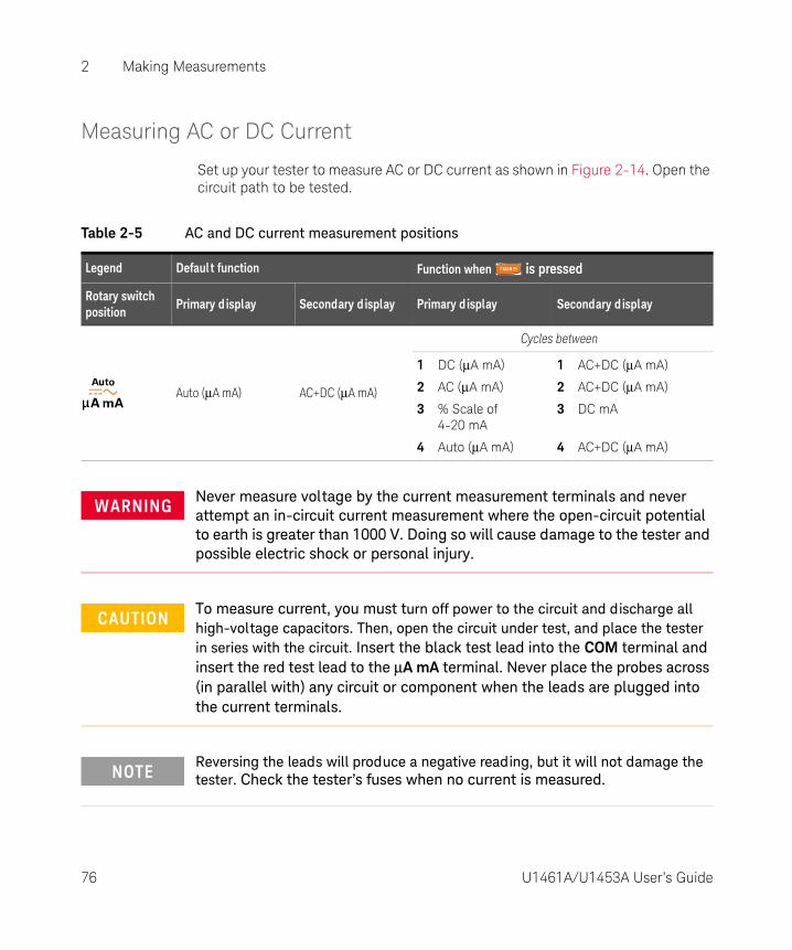
Measuring AC or DC Current
Set up your tester to measure AC or DC current as shown in Figure 2-14. Open the circuit path to be tested.
Table 2-5 AC and DC current measurement positions
Legend Defaul t function Function when is pressed
Rotary switch position
Primary d isplay Secondary d isplay Primary d isplay Secondary d isplay
Auto (μA mA) AC+DC (μA mA)
Cycles between
1 DC (μA mA)
2 AC (μA mA)
3 % Scale of 4-20 mA
4 Auto (μA mA)
1 AC+DC (μA mA)
2 AC+DC (μA mA)
3 DC mA
4 AC+DC (μA mA)
WARNINGNever measure voltage by the current measurement terminals and never attempt an in-circuit current measurement where the open-circuit potential to earth is greater than 1000 V. Doing so will cause damage to the tester and possible electric shock or personal injury.
CAUTIONTo measure current, you must turn off power to the circuit and discharge all high-voltage capacitors. Then, open the circuit under test, and place the tester in series with the circuit. Insert the black test lead into the COM terminal and insert the red test lead to the μA mA terminal. Never place the probes across (in parallel with) any circuit or component when the leads are plugged into the current terminals.
NOTEReversing the leads will produce a negative reading, but it will not damage the tester. Check the tester’s fuses when no current is measured.
76 U1461A/U1453A User’s Guide

Making Measurements 2
Figure 2-14 AC or DC current measurement example
3
2
AC
LOAD
DC
LOAD
1
CAUTIONPlacing the probes across (in parallel with) a powered circuit when a lead is plugged into a current terminal can damage the circuit you are testing and blow the tester's fuse. This happens because the resistance through the tester's current terminals are very low, resulting in a short circuit.
U1461A/U1453A User’s Guide 77

2 Making Measurements
% Scale of 4-20 mA or 0-20 mA
To display the current measurement in % scale, set up your tester to measure DC
current as shown in Figure 2-14, then press until the % scale is shown.
The analog bar graph displays the current measurement value. (In the example above, 24 mA is represented as 125% in the 4-20 mA % scale.)
You can change the % scale range (4-20 mA or 0-20 mA) in the Setup (page 157). Use the % scale with a pressure transmitter, a valve positioner, or other output actuators to measure pressure, temperature, flow, pH, or other process variables.
NOTE – Press to measure the frequency of the AC or DC current source. See “Measuring Frequency” on page 79 to learn more.
– The Auto function is able to automatically identify the signal component (AC or DC) of an electrical source. See “Auto AC or DC signal identification” on page 72 to learn more.
NOTE– The 4-20 mA current loop output from a transmitter is a type of electrical
signal that is used in a series circuit to provide a robust measurement signal that is proportional to the applied pressure, temperature, or flow in process control. The signal is a current loop where 4 mA represents the zero percent signal and 20 mA represents the 100 percent signal.
– The % scale for 4-20 mA or 0-20 mA in this tester is calculated using its corresponding DC mA measurement. The tester will automatically optimize the best resolution for the selected measurement. Two ranges are available for the % scale as shown in Table 2-6.
Table 2-6 % Scale measurement range
% Scale of 4-20 mA or 0-20 mA DC mA measurement range
999.99%6 μA or 600 mA[a]
9999.9%
[a] Applies to both autoranging and manual range selection.
78 U1461A/U1453A User’s Guide

Making Measurements 2
Measuring Frequency
Your tester allows simultaneous monitoring of real-time voltage or current with frequency measurements. To measure frequency, rotate the switch to one of the
positions highlighted in Table 2-7 and set up the tester accordingly. Press . Probe the test points, and read the display.
Table 2-7 Measurement positions allowing frequency measurements
Legend Defaul t function
Rotary switch position
Primary d isplay Secondary d isplay
AC V -
AC V -
Auto (V) AC+DC V
Auto (mV) AC+DC mV
Auto (μA mA) AC+DC (μA mA)
WARNINGNever measure the frequency where the voltage or current level exceeds the specified range. Manually set the voltage or current range if you want to measure frequencies below 20 Hz.
NOTE – Pressing controls the input range of the primary function (voltage or ampere) and not the frequency range.
– To obtain the best measuring results for frequency measurements, please use the AC measuring path.
U1461A/U1453A User’s Guide 79

2 Making Measurements
Frequency measurement techniques
– Measuring the frequency of a signal helps detect the presence of harmonic currents in neutral conductors and determines whether these neutral currents are the result of unbalanced phases or non-linear loads.
– Frequency is the number of cycles a signal completes each second. Frequency is defined as 1/Period. Period is defined as the time between the middle threshold crossings of two consecutive, like-polarity edges, as shown in Figure 2-15.
– The tester measures the frequency of a voltage or current signal by counting the number of times the signal crosses a threshold level within a specified period of time.
– If a reading shows as 0 Hz or is unstable, the input signal may be below or near the trigger level. You can usually correct these problems by manually selecting a lower input range, which increases the sensitivity of the tester.
– If a reading seems to be a multiple of what you expect, the input signal may be distorted. Distortion can cause multiple triggerings of the frequency counter. Selecting a higher voltage range might solve this problem by decreasing the sensitivity of the tester. In general, the lowest frequency displayed is the correct one.
– The frequency of the input signal is shown in the primary display. The voltage or ampere value of the signal is shown in the secondary display. The bar graph does not indicate frequency but indicates the voltage or ampere value of the input signal.
Figure 2-15 Definition of frequency
Rise Time Fall Time
+ Width – WidthPeriod
90%
50%
10%
80 U1461A/U1453A User’s Guide

Making Measurements 2
Measuring duty cycle and pulse width
You must first enable the duty cycle and pulse width display in the Setup menu. See “Enabling the (+ or –) duty cycle and pulse width display” on page 157 for more information.
While displaying voltage or current frequency, press to select the measurement as a percentage (%) for duty cycle or in the millisecond (ms) unit for pulse width.
NOTE– The duty cycle (or duty factor) of a repetitive pulse train is the ratio of the
positive or negative pulse width to the period expressed as a percentage. The duty-cycle function is optimized for measuring the on or off time of logic and switching signals. Systems such as electronic fuel injection systems and switching power supplies are controlled by pulses of varying width, which can be checked by measuring the duty cycle.
– The pulse width function measures the amount of time a signal is high or low. It is the time from the middle threshold of the rising edge to the middle threshold of the next falling edge. The measured waveform must be periodic; its pattern must repeat at equal time intervals.
– The bar graph does not indicate duty cycle or pulse width value but indicates the voltage or ampere value of the input signal.
– The duty cycle polarity is displayed to the left of the duty cycle value. indicates a positive pulse width and indicates a negative pulse width. Change the polarity in the Setup (see page 157).
U1461A/U1453A User’s Guide 81
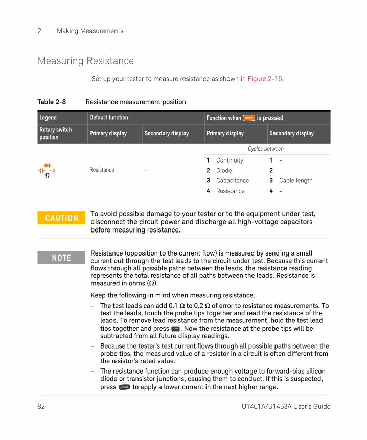
2 Making Measurements
82 U1461A/U1453A User’s Guide
Measuring Resistance
Set up your tester to measure resistance as shown in Figure 2-16.
Table 2-8 Resistance measurement position
Legend Defaul t function Function when is pressed
Rotary switch position
Primary d isplay Secondary d isplay Primary d isplay Secondary d isplay
Resistance -
Cycles between
1 Continuity
2 Diode
3 Capacitance
4 Resistance
1 -
2 -
3 Cable length
4 -
CAUTIONTo avoid possible damage to your tester or to the equipment under test, disconnect the circuit power and discharge all high-voltage capacitors before measuring resistance.
NOTEResistance (opposition to the current flow) is measured by sending a small current out through the test leads to the circuit under test. Because this current flows through all possible paths between the leads, the resistance reading represents the total resistance of all paths between the leads. Resistance is measured in ohms (Ω).
Keep the following in mind when measuring resistance.
– The test leads can add 0.1 Ω to 0.2 Ω of error to resistance measurements. To test the leads, touch the probe tips together and read the resistance of the leads. To remove lead resistance from the measurement, hold the test lead tips together and press . Now the resistance at the probe tips will be subtracted from all future display readings.
– Because the tester’s test current flows through all possible paths between the probe tips, the measured value of a resistor in a circuit is often different from the resistor’s rated value.
– The resistance function can produce enough voltage to forward-bias silicon diode or transistor junctions, causing them to conduct. If this is suspected, press to apply a lower current in the next higher range.
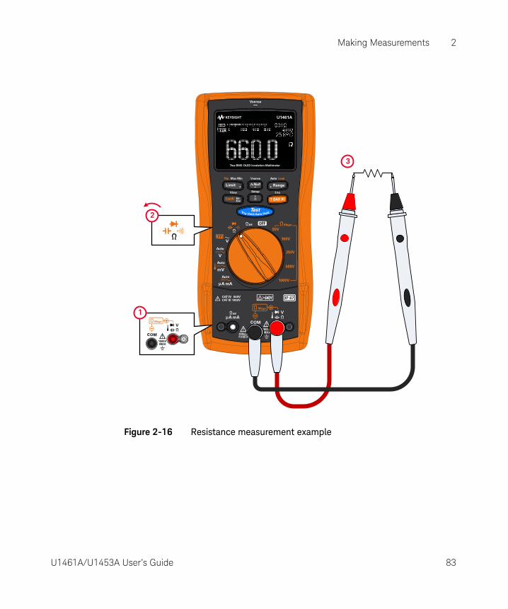
Making Measurements 2
Figure 2-16 Resistance measurement example
3
1
2
U1461A/U1453A User’s Guide 83

2 Making Measurements
Continuity Test
Set up your tester to perform continuity tests as shown in Figure 2-17. The beeper will sound and the red LED lights up as a continuity indication.
Table 2-9 Continuity test position
Legend Defaul t function Function when is pressed
Rotary switch position
Primary d isplay Secondary d isplay Primary d isplay Secondary d isplay
Resistance -
Cycles between
1 Continuity
2 Diode
3 Capacitance
4 Resistance
1 -
2 -
3 Cable length
4 -
CAUTIONTo avoid possible damage to your tester or to the equipment under test, disconnect the circuit power and discharge all high-voltage capacitors before testing for continuity.
NOTE– Continuity is the presence of circuit continuities. The beeper sounds as the
resistance falls down to the threshold, and the red LED indicator will be lit (if enabled in the Setup). The audible and visual alert allows you to perform quick continuity tests without having to watch the display.
– The continuity function detects intermittent shorts and opens lasting as short as 1 ms. A brief short causes the tester to emit a short beep.
– You can enable or disable the audible alert via the Setup. See “Changing the continuity alert” on page 140 for more information on the audible alert option.
84 U1461A/U1453A User’s Guide

Making Measurements 2
Figure 2-17 Continuity test example
3
ON (closed)
OFF (open)
1
2
4
U1461A/U1453A User’s Guide 85

2 Making Measurements
Diode Test
Set up your tester to perform diode tests as shown in Figure 2-18.
Table 2-10 Diode test position
Legend Defaul t function Function when is pressed
Rotary switch position
Primary d isplay Secondary d isplay Primary d isplay Secondary d isplay
Resistance -
Cycles between
1 Continuity
2 Diode
3 Capacitance
4 Resistance
1 -
2 -
3 Cable length
4 -
CAUTIONTo avoid possible damage to your tester or to the equipment under test, disconnect the circuit power and discharge all high-voltage capacitors before testing diodes.
NOTE– This test sends a current through a semiconductor junction, and then
measures the junction’s voltage drop. A typical junction drops 0.3 V to 0.8 V.
– Connect the red test lead to the positive terminal (anode) of the diode and the black test lead to the negative terminal (cathode). The cathode of a diode is indicated with a band.
– Your tester can display diode forward-bias of up to approximately 1 V. The forward-bias of a typical diode is within the range of 0.3 V to 0.8 V; however, the reading can vary depending on the resistance of other pathways between the probe tips.
– If the beeper is enabled during diode test, the tester will beep briefly for a normal junction and sound continuously for a shorted junction, below 0.04 ± 0.02 V approx. See “Changing the beep frequency” on page 131 to disable the beeper.
86 U1461A/U1453A User’s Guide
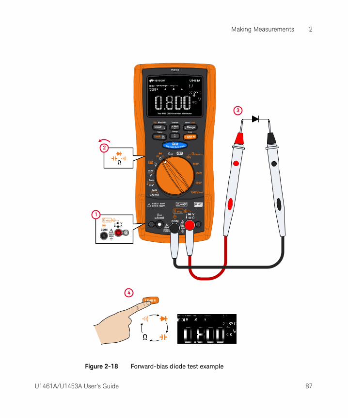
Making Measurements 2
Figure 2-18 Forward-bias diode test example
3
2
1
4
U1461A/U1453A User’s Guide 87
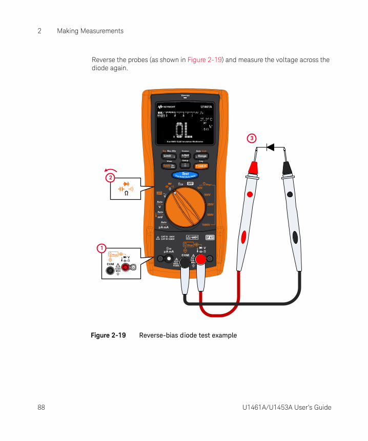
2 Making Measurements
Reverse the probes (as shown in Figure 2-19) and measure the voltage across the diode again.
Figure 2-19 Reverse-bias diode test example
3
2
1
88 U1461A/U1453A User’s Guide

Making Measurements 2
Assessing the diode condition
Assess the diode according to the following guidelines:
– A diode is considered good if the tester displays OL in reverse-bias mode.
– A diode is considered shorted if the tester displays approximately 0 V in both forward- and reverse-bias modes, and the tester beeps continuously.
– A diode is considered open if the tester displays OL in both forward- and reverse-bias modes.
Use the diode test to check diodes, transistors, silicon controlled rectifiers (SCRs), and other semiconductor devices. A good diode allows current to flow in one direction only.
Using the Auto-diode feature
Set up your tester to test diodes as shown in Figure 2-18 or Figure 2-19. Press
and hold to toggle the Auto-diode feature. Probe the test points, and read the display.
NOTEThe auto-diode function will help you test both forward- and reverse-bias directions simultaneously. You do not need to change the measuring direction to identify the diode’s condition.
Table 2-11 Auto-diode voltage thresholds
Forward vol tage Reverse vol tage Diode status
Primary d isplay Secondary d isplay GO NG
OL or <0.3 V or >0.8 V –OL or >–0.3 V or <–0.8 V ✘
Within 0.3 V to 0.8 V –OL ✔
OL Within –0.3 V to –0.8 V ✔
U1461A/U1453A User’s Guide 89

2 Making Measurements
The primary display shows the forward-bias voltage value. The reverse-bias voltage value is shown in the secondary display.
– GO is shown briefly (along with a single beep) if the diode is in a good condition.
– NG is shown briefly (along with two beeps) if the diode is out of the thresholds.
Figure 2-20 Auto-diode operation
NOTEThe open condition will not be alerted as OL on both directions if the auto-diode function is used.
Press and hold to enable the
Auto-diode feature.
GO: Diode good
GO: Diode good
GO: Diode good
GO: Diode good
NG: Diode shorted
90 U1461A/U1453A User’s Guide

Making Measurements 2
Measuring Capacitance
Set up your tester to measure capacitance as shown in Figure 2-21.
Table 2-12 Capacitance measurement position
Legend Defaul t function Function when is pressed
Rotary switch position
Primary d isplay Secondary d isplay Primary d isplay Secondary d isplay
Resistance -
Cycles between
1 Continuity
2 Diode
3 Capacitance
4 Resistance
1 -
2 -
3 Cable length
4 -
CAUTIONTo avoid possible damage to the tester or to the equipment under test, disconnect circuit power and discharge all high-voltage capacitors before measuring capacitance. Use the DC voltage function to confirm that the capacitor is fully discharged.
NOTE– The tester measures capacitance by charging the capacitor with a known
current for a known period of time, measuring the resulting voltage, and then calculating the capacitance.
– is shown on the bottom left of the display when the capacitor is charging, and is shown when the capacitor is discharging.
– To improve measurement accuracy of small value capacitors, press with the test leads open to subtract the residual capacitance of the tester and leads.
– For measuring capacitance values greater than 1000 μF, discharge the capacitor first, then select a suitable range for measurement. This will speed up the measurement time and also ensure that the correct capacitance value is obtained.
U1461A/U1453A User’s Guide 91

2 Making Measurements
Figure 2-21 Capacitance measurement example
3
+ –
1
2
4
92 U1461A/U1453A User’s Guide

Making Measurements 2
Viewing the cable length value
Press to temporarily display the cable length of the circuit under test in the secondary display.
The default cable length scale is 1 km per 40 nF (km/C). To change this value, see “Changing the cable length scale” on page 143.
You can also change the cable length unit (Meter or Feet). To change this value, see “Changing the cable length unit” on page 144.
U1461A/U1453A User’s Guide 93

2 Making Measurements
Measuring Temperature
The tester uses a type-K (default setting) temperature probe for measuring temperature. To measure temperature, set up your tester as shown in Figure 2-22.
The primary display normally shows temperature or the message OL (open thermocouple). The open thermocouple message may be due to a broken (open) probe or because no probe is installed into the input jacks of the tester.
Table 2-13 Temperature measurement position
Legend Defaul t function Function when is pressed
Rotary switch position
Primary d isplay Secondary d isplay Primary d isplay Secondary d isplay
Auto (mV) AC+DC mV
Cycles between
1 DC mV
2 AC mV
3 Temperature
4 Auto (mV)
1 AC+DC mV
2 AC+DC mV
3 -, °C, or °F
4 AC+DC mV
WARNINGDo not connect the thermocouple to electrically live circuits. Doing so will potentially cause fire or electric shock.
CAUTIONDo not bend the thermocouple leads at sharp angles. Repeated bending over a period of time can break the leads.
NOTE – Shorting the terminal to the COM terminal will display the temperature at the tester’s terminals.
– To change the default thermocouple type from type-K to type-J, see “Changing the thermocouple type” on page 155 for more information.
94 U1461A/U1453A User’s Guide
Making Measurements 2
Changing the temperature unit
Press to change the temperature units between °C or °F (you must first change the temperature unit to switch between °C and °F or °F and °C). See “Changing the temperature unit” on page 155 for more information.
NOTEThe bead-type thermocouple probe is suitable for measuring temperatures from –40 °C to 204 °C (399 °F) in PTFE-compatible environments. Do not immerse this thermocouple probe in any liquid. For best results, use a thermocouple probe designed for each specific application — an immersion probe for liquid or gel, and an air probe for air measurement.
Observe the following measurement techniques:
– Clean the surface to be measured, and ensure that the probe is securely touching the surface. Remember to disable the applied power.
– When measuring above ambient temperatures, move the thermocouple along the surface until you get the highest temperature reading.
– When measuring below ambient temperatures, move the thermocouple along the surface until you get the lowest temperature reading.
– Place the tester in the operating environment for at least 1 hour as the tester is using a non-compensation transfer adapter with miniature thermal probe.
For quick measurement, use the compensation to view the temperature variation of the thermocouple sensor. The compensation assists you in measuring relative temperature immediately.
CAUTIONThe option to change the temperature unit is locked for certain regions. Always set the temperature unit display per the official requirements and in compliance with the National laws of your region.
U1461A/U1453A User’s Guide 95
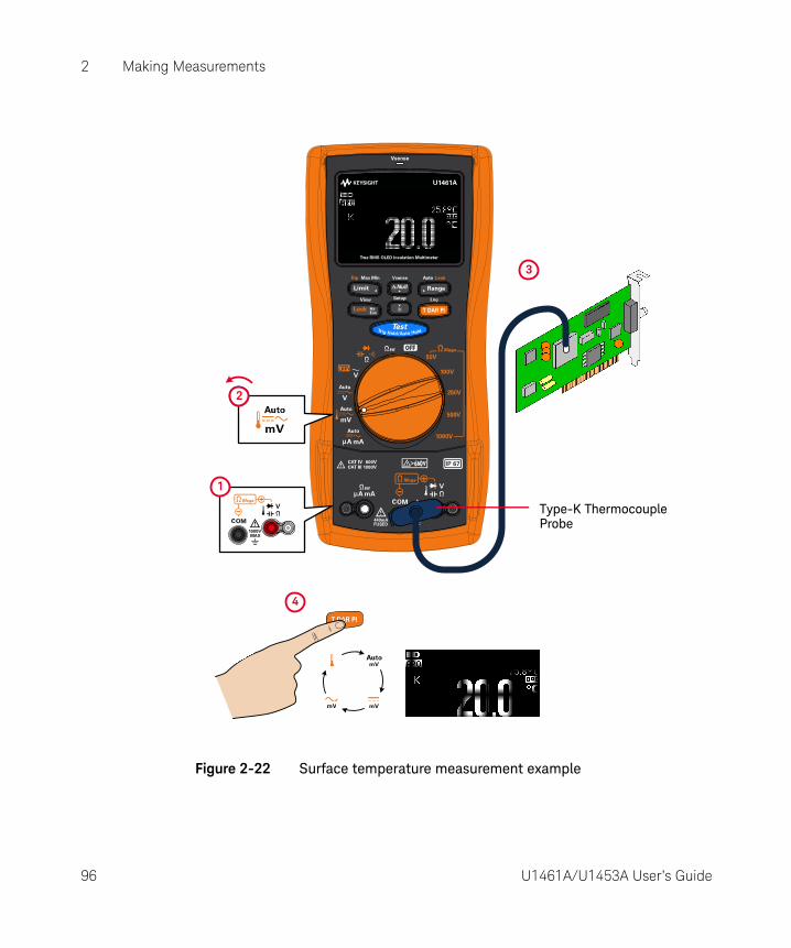
2 Making Measurements
Figure 2-22 Surface temperature measurement example
3
1
22
Type-K Thermocouple
4
Probe
96 U1461A/U1453A User’s Guide
Making Measurements 2
Temperature measurement without ambient compensation
If you are working in a constantly varying environment, where ambient temperatures are not constant, do the following:
1 Press for more than 1 second to select compensation. This allows a quick measurement of the relative temperature.
2 Avoid contact between the thermocouple probe and the surface to be measured.
3 After a constant reading is obtained, press to set the reading as the relative reference temperature.
4 Touch the surface to be measured with the thermocouple probe and read the display.
U1461A/U1453A User’s Guide 97

2 Making Measurements
THIS PAGE HAS BEEN INTENTIONALLY LEFT BLANK.
98 U1461A/U1453A User’s Guide

U1461A Insulation Multimeter/U1453A Insulation TesterUser’s Guide
3 Tester Features
Non-Contact AC Voltage Detection (Vsense) 100Making Relative Measurements (Null) 102Capturing Maximum and Minimum Values (Max Min) 103Freezing the Display (TrigHold and AutoHold) 105Performing Limit Comparisons (Limit) 106Recording Measurement Data (Log) 108Reviewing Previously Recorded Data (View) 113
The following sections describe the additional features available in your tester.
99

3 Tester Features
Non-Contact AC Voltage Detection (Vsense)
For model U1461A only: Vsense is a non-contact voltage detector that detects the presence of AC voltages nearby.
1 Press and hold to enable Vsense (on any position of the rotary switch except ).
2 Press to toggle the Vsense’s sensitivity between HIGH SENSE (high sensitivity) or LOW SENSE (low sensitivity).
3 Press and hold again to disable Vsense.
WARNING– You are advised to test on a known live circuit within the rated AC voltage
range of this product before and after each use to ensure that Vsense works.
– Voltage could still be present even if there is no Vsense alert indication. Do not rely on Vsense with shielded wires. Never touch live voltage or conductor without the necessary insulation protection or power off the voltage source.
– Vsense may be affected by differences in socket design, insulation thickness, and insulation type.
CAUTIONYou are advised to measure voltage by using test leads through the voltage measurement function after using Vsense, even if there is no alert indication.
NOTEIf the presence of AC voltage is sensed, the tester will beep and the Vsense red LED at the top of the tester will turn on. The audible and visual alert allows you to easily sense nearby AC voltage presence.
No resolution and accuracy of voltage measurement will be d isplayed in this mode.
100 U1461A/U1453A User’s Guide

Tester Features 3
NOTEPlace the top of the tester close to a conductor when sensing for AC voltages (as low as 24 V in the high sensitivity setting). The high sensitivity setting allows for AC voltage sensing on other styles of recessed power connectors or sockets where the actual AC voltage is recessed within the connector itself. The low sensitivity setting can be used on flush mounted wall sockets or outlets and various power strips or cords.
Figure 3-1 Detecting AC voltage example
1
2
AC
33
U1461A/U1453A User’s Guide 101
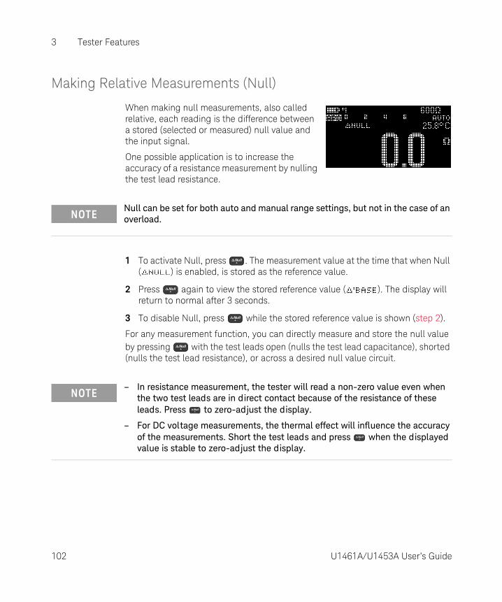
3 Tester Features
Making Relative Measurements (Null)
When making null measurements, also called relative, each reading is the difference between a stored (selected or measured) null value and the input signal.
One possible application is to increase the accuracy of a resistance measurement by nulling the test lead resistance.
1 To activate Null, press . The measurement value at the time that when Null ( ) is enabled, is stored as the reference value.
2 Press again to view the stored reference value ( ). The display will return to normal after 3 seconds.
3 To disable Null, press while the stored reference value is shown (step 2).
For any measurement function, you can directly measure and store the null value by pressing with the test leads open (nulls the test lead capacitance), shorted (nulls the test lead resistance), or across a desired null value circuit.
NOTENull can be set for both auto and manual range settings, but not in the case of an overload.
NOTE– In resistance measurement, the tester will read a non-zero value even when
the two test leads are in direct contact because of the resistance of these leads. Press to zero-adjust the display.
– For DC voltage measurements, the thermal effect will influence the accuracy of the measurements. Short the test leads and press when the displayed value is stable to zero-adjust the display.
102 U1461A/U1453A User’s Guide

Tester Features 3
Capturing Maximum and Minimum Values (Max Min)
The Max Min operation stores the maximum, minimum, and average input values during a series of measurements.
When the input goes below the recorded minimum value or above the recorded maximum value, the tester beeps and records the new value. The elapsed time since the recording session was started is stored and shown on the display at the same time. The tester also calculates an average of all readings taken since Max Min was activated.
From the tester’s display, you can view the following statistical data for any set of readings:
– REC MAX: highest reading since Max Min was enabled
– REC MIN: lowest reading since Max Min was enabled
– REC AVG: average or mean of all readings since Max Min was enabled
– REC NOW: present reading (actual input signal value)
1 Press and hold to enable Max Min.
2 Press again to cycle through the MAX, MIN, AVG, or NOW (present) input values.
3 The elapsed time is shown on the display. Press to restart the recording session.
4 Press and hold again to disable Max Min.
U1461A/U1453A User’s Guide 103

3 Tester Features
Max Min is useful for capturing intermittent readings, recording minimum and maximum readings unattended, or recording readings while equipment operation keeps you from observing the tester display.
The true average value displayed is the arithmetic mean of all readings taken since the start of recording. The average reading is useful for smoothing out unstable inputs, calculating power consumption, or estimating the percentage of time a circuit is active.
NOTE– Changing the range manually will also restart the recording session.
– You can also use Max Min while measuring frequency (see “Measuring Frequency” on page 79). If the measured frequency shown is not reflected accurately, press again to restart the recording session.
– If an overload is recorded, the averanging function will be stopped. OL is shown in place of the average value.
– The APO (auto power-off) function is disabled when Max Min is enabled.
– The maximum recording time is 99999 seconds (1 day, 3 hours, 46 minutes, 39 seconds). OL is shown if the recording exceeds the maximum time.
104 U1461A/U1453A User’s Guide

Tester Features 3
Freezing the Display (TrigHold and AutoHold)
TrigHold operation
Press to freeze the display for any function, except for the Ω Mega or the Ω EB function.
AutoHold operation
Press and hold to activate AutoHold for any function, except for the Ω Mega or the Ω EB function.
AutoHold monitors the input signal and updates the display and, if enabled, emits a beep, whenever a new stable measurement is detected. A trigger point is one that varies more than a selected adjustable (AutoHold threshold) variation count (default 500 counts based on DDDDD option selected in Setup). Open lead conditions are not included in the update.
To change the default AutoHold threshold count see “Changing the variation count” on page 125 for more information.
NOTE Pressing when the rotary switch is in one of the Ω Mega or the Ω EB position will result in a test being performed instead.
NOTE Pressing and holding when the rotary switch is in one of the Ω Mega or the Ω EB position will result in a test being performed instead.
NOTEIf the reading value is unable to reach a stable state, the reading value will not be updated.
U1461A/U1453A User’s Guide 105

3 Tester Features
Performing Limit Comparisons (Limit)
Limit is used to compare the test result with the chosen settling value. The default settling values are shown in the table below.
Table 3-1 Hi/Lo default settling values
Function Limit settl ing defaul t value Limit settl ing range
HI LO HI LO
Voltage measurement >+30 V <–30 V LO to +9999.9 V –9999.9 V to HI
Voltage measurement (up to millivolts) >+30 mV <–30 mV LO to +999.99 mV –999.99 mV to HI
Temperature measurement >+100º <–100º LO to +9999.9º –9999.9º to HI
Resistance measurement >+10 Ω <+10 Ω LO to +99.999 MΩ –99.999 MΩ to HI
Capacitance measurement >+10 nF <+10 nF LO to +9.9999 mF –9.9999 mF to HI
Diode test >+0.8 V <+0.3 V LO to +9.9999 V –9.9999 V to HI
Earth-bond resistance test >+10 Ω <+10 Ω LO to +99.999 kΩ –99.999 kΩ to HI
Current measurement >+30 mA <+0 mA LO to +999.99 mA –999.99 mA to HI
Insulation resistance test >+10 MΩ <+10 MΩ LO to +999.99 GΩ –999.99 GΩ to HI
Frequency measurement >+999.99 Hz <+0 Hz LO to +999.99 kHz +000.00 Hz to HI
Pulse width measurement >+000.50 ms <+0 ms LO to +9999.9 ms +000.00 ms to HI
Duty cycle measurement >+050.00% <+0% LO to +999.99% +000.00% to HI
106 U1461A/U1453A User’s Guide

Tester Features 3
You can select four different modes for Limit:
1 Press to activate Limit.
2 Press again to set the comparison value. Use the arrow keys to position the cursor and to change the value shown.
3 Position the cursor on the HI symbol to change the Limit mode.
4 Press to save your changes (or press to discard your changes).
5 If the new value is passed:
– GO is shown briefly
– A short beep tone is heard
6 If the new values is failed:
– For LIMIT HI or LIMIT LO mode: HI or LO is shown briefly along with the fail cause
– For LIMIT H> or LIMIT L< mode: NG is shown briefly
– Three short beep tones are heard
– The red LED lights up
Limit mode GO NG
LIMIT HI or LIMIT LO LO limit < Reading < HI limitReading < LO limit, orReading > HI limit
LIMIT H> Reading > HI limit Reading ≤ HI limit
LIMIT L< Reading < LO limit Reading ≥ LO limit
NOTEWhen the Limit feature is enabled for insulation resistance tests, the red LED indicator lights up accordingly to the changes in the limit values instead of blinking every 2 seconds.
U1461A/U1453A User’s Guide 107

3 Tester Features
Recording Measurement Data (Log)
Log provides you with the convenience of recording test data for future review or analysis. Since data is stored in the nonvolatile memory, the data remains saved even when the tester is turned OFF or if the battery is replaced.
Log collects measurement information over a user-specified duration. There are three Log options that can be used to capture measurement data: manual (HAND), interval (AUTO), or event (TRIG).
– A manual log stores an instance of the measured signal each time you press
and hold (see page 109).
– An interval log stores a record of the measured signal at a user-specified interval (see page 109).
– An event log stores a record of the measured signal each time a trigger condition is satisfied (see page 110).
Before starting a recording session, set up the tester for the measurements to be recorded.
To change the Log option see “Changing the recording option” on page 126 for more information.
See “Reviewing Previously Recorded Data (View)” on page 113 to review or erase the recorded entries.
Table 3-2 Log maximum capacity
Log option Maximum capacity for saving
Manual (HAND) 100
Interval (AUTO) 3000
Event (TRIG) 3000
NOTEEach recorded index includes two parameters: the primary display and the secondary display. Examples include IR-V or Hz-V.
108 U1461A/U1453A User’s Guide

Tester Features 3
Performing manual logs (HAND)
Ensure that HAND is selected as the Log option in the Setup.
1 Press and hold to store the present input signal value.
and the log entry number are displayed. The display will return to normal after a short while (around 1 second).
2 Repeat step 1 again to save the next input signal value.
The maximum number of readings that can be stored for the manual log is 100 entries. When all entries are occupied, H : FULL will be shown when you press and
hold .
Performing interval logs (AUTO)
Ensure that AUTO is selected as the Log option in the Setup.
The default recording interval duration is 1 second. To change the recording interval duration, see “Changing the sample interval duration” on page 126 for more information.
The duration set in the Setup will determine how long each recording interval takes. The input signal value at the end of each interval will be recorded and saved into the tester’s memory.
Start the interval log mode
1 Press and hold to start interval log mode.
and the log entry number are displayed. Subsequent readings are automatically recorded into the tester’s memory at the interval specified in the Setup.
2 Press and hold again to exit the interval log mode.
U1461A/U1453A User’s Guide 109

3 Tester Features
The maximum number of readings that can be stored for the interval log is 3000 entries. When all entries are occupied, A : FULL will be shown when you press and
hold .
Performing event logs (TRIG)
Ensure that TRIG is selected as the Log option in the Setup.
Event logs are used only with the following modes:
– TrigHold and AutoHold (page 105)
– Max Min recordings (page 103)
– Limit comparisons (page 106)
– Earth-bond resistance tests (page 67)
– Insulation resistance tests (page 67)
– T/DAR/PI tests (page 52)
Event records are triggered by the measured signal satisfying a trigger condition set by the measurement function used in the following modes (shown in Table 3-3 on page 111):
NOTEWhen the interval log recording session is running, all other keypad operations
are disabled; except for , which, when pressed for more than 1 second, will stop and exit the recording session. Furthermore, APO (auto power-off) is disabled during the recording session.
110 U1461A/U1453A User’s Guide
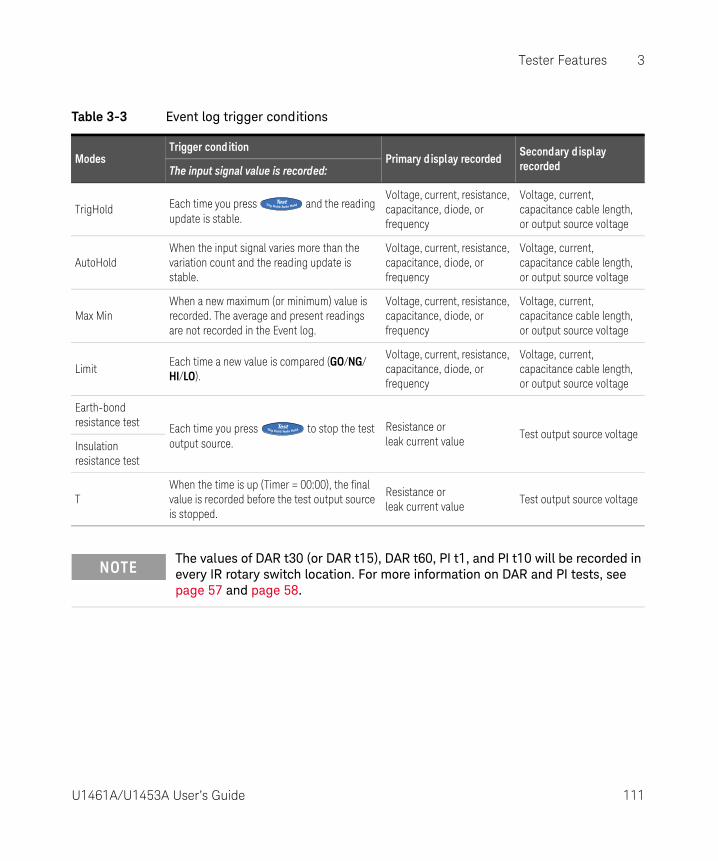
Tester Features 3
Table 3-3 Event log trigger conditions
ModesTrigger condition
Primary d isplay recordedSecondary d isplay recordedThe input signal value is recorded:
TrigHold Each time you press and the reading update is stable.
Voltage, current, resistance, capacitance, diode, or frequency
Voltage, current, capacitance cable length, or output source voltage
AutoHoldWhen the input signal varies more than the variation count and the reading update is stable.
Voltage, current, resistance, capacitance, diode, or frequency
Voltage, current, capacitance cable length, or output source voltage
Max MinWhen a new maximum (or minimum) value is recorded. The average and present readings are not recorded in the Event log.
Voltage, current, resistance, capacitance, diode, or frequency
Voltage, current, capacitance cable length, or output source voltage
LimitEach time a new value is compared (GO/NG/HI/LO).
Voltage, current, resistance, capacitance, diode, or frequency
Voltage, current, capacitance cable length, or output source voltage
Earth-bond resistance test Each time you press to stop the test
output source.Resistance or leak current value
Test output source voltageInsulation resistance test
TWhen the time is up (Timer = 00:00), the final value is recorded before the test output source is stopped.
Resistance or leak current value
Test output source voltage
NOTEThe values of DAR t30 (or DAR t15), DAR t60, PI t1, and PI t10 will be recorded in every IR rotary switch location. For more information on DAR and PI tests, see page 57 and page 58.
U1461A/U1453A User’s Guide 111

3 Tester Features
Start the event log mode
1 Select one of the six modes listed in Table 3-3.
2 Press and hold to start event log mode.
and the log entry number are displayed. The primary display and secondary display readings will be recorded into the memory. Subsequent readings are automatically recorded into the tester’s memory every time the trigger condition specified in Table 3-3 is satisfied.
3 Press and hold again to exit the event log mode.
The maximum number of readings that can be stored for the event log is 3000 entries. When all entries are occupied, E : FULL will be shown when you press and
hold .
NOTEAPO (auto power-off) is disabled during the recording session.
112 U1461A/U1453A User’s Guide

Tester Features 3
U1461A/U1453A User’s Guide 113
Reviewing Previously Recorded Data (View)
Viewing data stored in the tester’s memory is
performed through the key.
1 Press and hold to View the previously
recorded data. Press again to cycle through the manual (H), interval (A), or event (E) records.
If nothing has been recorded, H : Void, A : Void, or E : Void will be displayed instead.
2 Select the desired recording category to view its entries.
a Press to jump to the first stored entry. Press to jump to the last stored entry.
b Press to view the next stored entry. The index number increases by one. Press to view the previous stored entry. The index number decreases by one.
c Press to clear the last stored entry for the selected log type. Press
and hold to clear all entries for the selected log type.
3 Press and hold again to exit the View mode.
Sanitizing the Log MemoriesYou have the option to sanitize the log memories of your tester. This operation erases the log memories of your tester thoroughly. The data stored in the tester’s memory will not be able to be reconstructed in any way after the data sanitization operation.
Prior to sanitizing the log memories, ensure that all manual (H), interval (A), or event (E) records have been cleared (see step c).When all entries are cleared (H : Void, A : Void, and E : Void), press and hold to sanitize the log memories.
CAUTIONThe data sanitization operation may take up to 30 seconds to complete. Do not press any keys or turn the rotary switch until the data sanitization operation is completed.

3 Tester Features
THIS PAGE HAS BEEN INTENTIONALLY LEFT BLANK.
114 U1461A/U1453A User’s Guide

U1461A Insulation Multimeter/U1453A Insulation TesterUser’s Guide
4 Setup Options
Using the Setup Menu 116Setup Menu Summary 118Setup Menu Items 125
The following sections describe how to change the preset features of your tester.
115

4 Setup Options
Using the Setup Menu
The Setup menu allows you to change a number of nonvolatile preset features. Modifying these settings affects the general operation of your tester across several functions. Select a setting to edit to perform one of the following actions:
– Switch between two values, such as on or off.
– Cycle through multiple values from a predefined list.
– Decrease or increase a numerical value within a fixed range.
The contents of the Setup menu are summarized in Table 4-2 on page 118.
Table 4-1 Setup menu key functions
Legend Description
– Press for more than 1 second to access the Setup menu.
– Press and hold until the tester restarts to exit the Setup menu.
– Arrow keys left and right
– Press or to browse each menu page.
– Arrow keys up and down
– Press or at each menu page to move the cursor to a specific menu item.
– Press to edit the selected menu item. The menu item’s value will flash to indicate that you can now change the value shown.
– Press or again to switch between two values, to cycle through multiple values from a list, or to decrease or increase a numerical value.
– Press to save your changes.
– While the menu item’s value is flashing, press to discard your changes.
NOTEThe tester will automatically exit the Setup menu after 30 seconds of inactivity.
116 U1461A/U1453A User’s Guide

Setup Options 4
Editing numerical values
When editing numerical values, use the and to position the cursor on a numerical digit.
– Press to move the cursor to the left, and
– Press to move the cursor to the right.
When the cursor is positioned over a digit, use the and keys to change the numerical digit.
– Press to increment the digit, and
– Press to decrement the digit.
When you have completed your changes, save the new numerical value by
pressing . (Or alternatively, if you wish to discard the changes you made,
press .)
Press and hold for more than 1 second to enter the Setup menu.
Press to edit the selected menu item’s value.
Press or to move the cursor left
or right.
Press or to increment or decrement the selected digit.
Press again to save the changes made.
U1461A/U1453A User’s Guide 117

4 Setup Options
Setup Menu Summary
The Setup menu items are summarized in the table below. Click the respective “Learn more” pages for more information on each menu item.
Table 4-2 Setup menu item descriptions
Menu Legend Available settings Description Learn more on:
MENU 1
AHOLD 00500 to 99999
Set the AutoHold threshold count from 5 to 99999 counts (or 9999 counts, depending on the display count selected).Default is 500 counts.
page 125
D-LOG HAND, AUTO, or TRIGSet the data logging option (HAND: manual log, AUTO: interval log, or TRIG: event log). Default is manual log.
page 126
LOG TIME 00001 S to 99999 S
Set the logging duration for interval logs from 1 to 99999 seconds (1 day, 3 hours, 46 minutes, 39 seconds). Default is 1 second.
page 126
D-UPDATE05, 10, 20, or 40 times
per second
Set the data update rate for voltage, current, resistance, and diode measurements. Default is 5 times per second.
page 127
SMOOTH00001 to 99999
(D or E)
Set the settling value from 00001 to 99999. You can also disable this feature (D).Default is disabled (00009-D).
page 128
118 U1461A/U1453A User’s Guide

Setup Options 4
MENU 2
DMM COUNTS DDDDD or DDDDSet the voltage, current, and frequency display count.Default is DDDD
page 130
Cx COUNTS DDDDD, DDDD, or DDDSet the capacitance display count.Default is DDDD
page 130
Rx COUNTS DDDDD, DDDD, or DDDSet the resistance display count.Default is DDDD
page 130
EBR COUNTS DDDD or DDDSet the earth-bond resistance display count.Default is DDDD
page 130
IR COUNTS DDDD or DDDSet the insulation resistance display count.Default is DDD
page 130
MENU 3
BEEP3200 Hz to 4267 Hz,
or OFF
Set the beep frequency from 3200 Hz to 4267 Hz. You can also disable this feature (off ).Default is 3840 Hz.
page 131
APO01 m to 99 m
(E or D)
Set the auto power-off timer period from 1 to 99 minutes (1 hour, 39 minutes). You can also disable this feature (D).Default is 10 minutes (10 m-E).
page 132
BACKLIT LOW, MEDIUM, HIGH,
or AUTO-(01 to 99)
Set the default OLED behavior from low to high. You can also set the OLED to auto-dim (AUTO) and change the auto-dim settling time (1 to 99 seconds).Default is auto-dim (AUTO-90).
page 132
MELODYFACTORY, USER, BEEE,
or OFF
Set the power-on melody to the factory default, a beep, or disable this feature (off ).Default is BEEE.
page 133
GREETING FACTORY, USER, or OFFSet the power-on greetings to the factory default or disable this feature (off ).Default is FACTORY.
page 134
Table 4-2 Setup menu item descriptions (continued)
Menu Legend Available settings Description Learn more on:
U1461A/U1453A User’s Guide 119
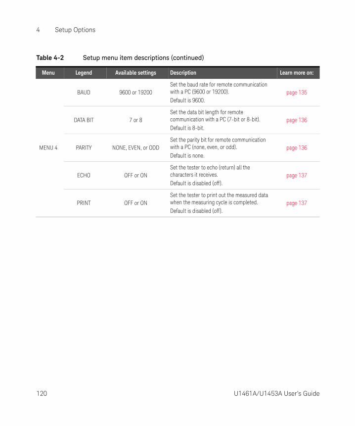
4 Setup Options
MENU 4
BAUD 9600 or 19200Set the baud rate for remote communication with a PC (9600 or 19200). Default is 9600.
page 135
DATA BIT 7 or 8Set the data bit length for remote communication with a PC (7-bit or 8-bit). Default is 8-bit.
page 136
PARITY NONE, EVEN, or ODDSet the parity bit for remote communication with a PC (none, even, or odd). Default is none.
page 136
ECHO OFF or ONSet the tester to echo (return) all the characters it receives.Default is disabled (off ).
page 137
PRINT OFF or ONSet the tester to print out the measured data when the measuring cycle is completed.Default is disabled (off ).
page 137
Table 4-2 Setup menu item descriptions (continued)
Menu Legend Available settings Description Learn more on:
120 U1461A/U1453A User’s Guide

Setup Options 4
MENU 5
REVISION - Displays the tester’s firmware revision. -
S/N -Displays the tester’s serial number (only the last eight digits).
-
DUAL DC+AC YES or NO
Enable dual display for voltage and current measurements. (AC+DC measurements are shown on the secondary display.)Default is yes.
page 139
ALERT HORNBEE&LED, OFF&LED, BEE&OFF, OFF&OFF
Set the tester to beep momentarily and light up the red LED indicator for limit and continuity alerts. You can also disable either or both alerts (off ). Default is to beep momentarily and light up the red LED indicator (BEE&LED).
page 140
CONTINUITYSHORT, OPEN, or TONE
(E or D)
Set the tester to sound a single beep or a tone during continuity alerts for short or open circuits. You can also disable this feature (D). Default is a single beep for short circuits (SHORT-E).
page 140
Table 4-2 Setup menu item descriptions (continued)
Menu Legend Available settings Description Learn more on:
U1461A/U1453A User’s Guide 121
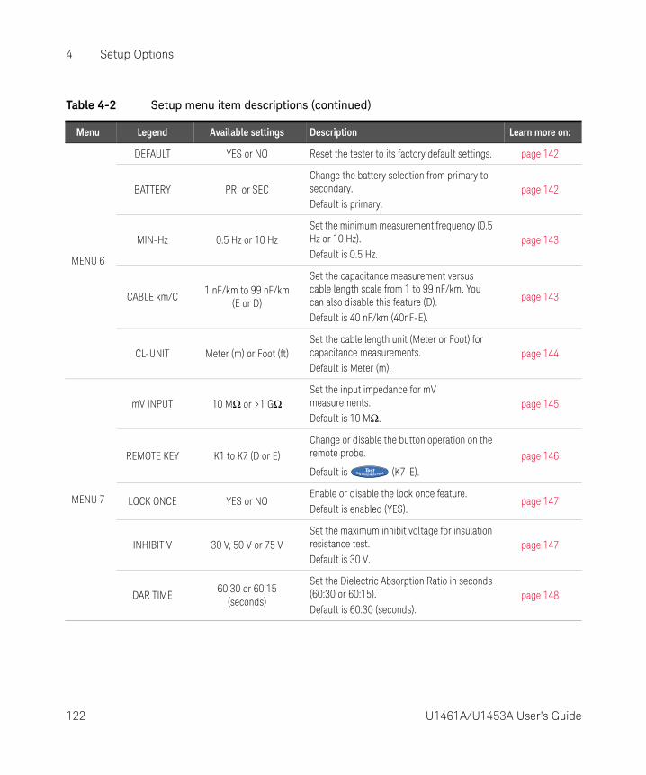
4 Setup Options
MENU 6
DEFAULT YES or NO Reset the tester to its factory default settings. page 142
BATTERY PRI or SECChange the battery selection from primary to secondary.Default is primary.
page 142
MIN-Hz 0.5 Hz or 10 HzSet the minimum measurement frequency (0.5 Hz or 10 Hz). Default is 0.5 Hz.
page 143
CABLE km/C1 nF/km to 99 nF/km
(E or D)
Set the capacitance measurement versus cable length scale from 1 to 99 nF/km. You can also disable this feature (D).Default is 40 nF/km (40nF-E).
page 143
CL-UNIT Meter (m) or Foot (ft)Set the cable length unit (Meter or Foot) for capacitance measurements.Default is Meter (m).
page 144
MENU 7
mV INPUT 10 MΩ or >1 GΩSet the input impedance for mV measurements.Default is 10 MΩ.
page 145
REMOTE KEY K1 to K7 (D or E)
Change or disable the button operation on the remote probe.
Default is (K7-E).
page 146
LOCK ONCE YES or NOEnable or disable the lock once feature.Default is enabled (YES).
page 147
INHIBIT V 30 V, 50 V or 75 VSet the maximum inhibit voltage for insulation resistance test.Default is 30 V.
page 147
DAR TIME60:30 or 60:15
(seconds)
Set the Dielectric Absorption Ratio in seconds (60:30 or 60:15).Default is 60:30 (seconds).
page 148
Table 4-2 Setup menu item descriptions (continued)
Menu Legend Available settings Description Learn more on:
122 U1461A/U1453A User’s Guide

Setup Options 4
MENU 8
IR: 50 VF 50 V or
U (10 to 60) V
Set the insulation resistance test voltage to the factory default or user-defined.Default is factory.
page 149
IR: 100 VF 100 V or
U (10 to 120) V
IR: 250 VF 250 V or
U (10 to 300) V
IR: 500 VF 500 V or
U (10 to 600) V
IR: 1000 VF 1000 V or
U (10 to 1100) V
MENU 9
TEST TIME 00:05 to 59:59Set the insulation resistance or earth-bond resistance test period.Default is 1 minute (01:00)
page 151
SCAN TIME 1 to 99 (seconds)Set the dwelling time for each step in the Scan function.Default is 10 seconds.
page 151
SCAN STEP 001 to 100Set the number of steps for the Scan function.Default is 5 steps.
page 152
RAMP STEP 0001 to 1000Set the number of steps for the Ramp function.Default is 100 steps.
page 153
TRIP mA 0.001 mA to 1.500 mASet the trip current level.Default is 1.000 mA.
page 153
Table 4-2 Setup menu item descriptions (continued)
Menu Legend Available settings Description Learn more on:
U1461A/U1453A User’s Guide 123

4 Setup Options
MENU
10[a]
T-TYPE J or KSet the thermocouple type (type J or type K) for temperature measurements. Default is type K.
page 155
T-UNIT °C, °F/°C, °C/°F, or °F
Set the temperature unit (Celsius, Fahrenheit/Celsius, Celsius/Fahrenheit, or Fahrenheit) for temperature measurements. Default is °C (Celsius).
page 155
LPF ON or OFF
Enable the low-pass filter to filter out higher frequencies with (AC/DC path) V, mV, μA, or mA measurements.Default is off.
page 156
mA SCALE0-20 mA or 4-20 mA
(D or E)
Set the % scale selection (0-20 mA or 4-20 mA) for DC current measurements. You can also disable this feature (D).Default is disabled (4-20mA-D).
page 157
% & ms +CYCLE-D
Set + or – cycle for duty cycle and pulse width measurements. You can also disable this feature (D).Default is disabled (+CYCLE-D).
page 157
MENU
11[a] LEAD ALERT NONE, USER, or AUTO Set the beep type for the lead alert.
[a] Model U1453A and U1461A only.
Table 4-2 Setup menu item descriptions (continued)
Menu Legend Available settings Description Learn more on:
124 U1461A/U1453A User’s Guide

Setup Options 4
Setup Menu Items
Menu 1
Changing the variation count
This setting is used with the AutoHold feature (see page 105). When the variation of the measured value exceeds the value of the variation count, the AutoHold feature will be ready to trigger.
Menu Items Learn more on:
AHOLD “Changing the variation count” on page 125
D-LOG “Changing the recording option” on page 126
LOG TIME “Changing the sample interval duration” on page 126
D-UPDATE “Changing the data update rate” on page 127
SMOOTH “Enabling smooth mode” on page 128
Parameter Range Defaul t setting
AHOLD (5 to 99999) counts 00500
U1461A/U1453A User’s Guide 125

4 Setup Options
To change the variation count:
1 Press for more than 1 second to enter the Setup menu.
2 Browse to Menu 1 > AHOLD, and press to edit the value.
3 Use the arrow keys to change the variation count.
4 Press to save your changes (or press to discard your changes).
5 Press and hold until the tester restarts to return to normal operation.
Changing the recording option
This setting is used with the Data Logging feature (see page 108). There are three available recording options for the Data Logging feature.
– HAND: Manual log
– AUTO: Interval log
– TRIG: Event log
To change the recording option:
1 Press for more than 1 second to enter the Setup menu.
2 Browse to Menu 1 > D-LOG, and press to edit the value.
3 Use the arrow keys to change the recording option.
4 Press to save your changes (or press to discard your changes).
5 Press and hold until the tester restarts to return to normal operation.
Changing the sample interval duration
This setting is used with the Interval Data Logging feature (see page 109). The tester will record a measurement value at the beginning of every sample interval.
Parameter Range Defaul t setting
D-LOG HAND, AUTO, or TRIG HAND
126 U1461A/U1453A User’s Guide

Setup Options 4
To change the sample interval duration:
1 Press for more than 1 second to enter the Setup menu.
2 Browse to Menu 1 > LOG TIME, and press to edit the value.
3 Use the arrow keys to change the sample interval duration.
4 Press to save your changes (or press to discard your changes).
5 Press and hold until the tester restarts to return to normal operation.
Changing the data update rate
This setting is used to increase the data update rate for voltage, current, resistance, and diode measurements.
To change the data update rate:
1 Press for more than 1 second to enter the Setup menu.
2 Browse to Menu 1 > D-UPDATE, and press to edit the value.
3 Use the arrow keys to change the data update rate.
4 Press to save your changes (or press to discard your changes).
5 Press and hold until the tester restarts to return to normal operation.
Parameter Range Defaul t setting
LOG TIME (1 to 99999) s 00001 S
Parameter Range Defaul t setting
D-UPDATE 5, 10, 20, or 40 times per second 5 times per second
U1461A/U1453A User’s Guide 127

4 Setup Options
Enabling smooth mode
Smooth is used to smoothen the refresh rate of the readings in order to reduce the impact of unexpected noise and to help you achieve a stable reading.
The smooth refresh rate can be set from 00001 to 99999. The smooth time is defined as the set value +1. Smooth will be restarted when the variation count is exceeded, when the range is changed, or after a tester function or feature is enabled. The variation count is set to the value used for the AutoHold feature (see “Changing the variation count” on page 125).
You can enable Smooth by holding while turning on the tester (“Your Tester in Brief” on page 28). This method, however, is temporary and Smooth will be turned off when you cycle the tester’s power. You can permanently enable Smooth from the Setup menu.
To change the smooth refresh rate:
1 Press for more than 1 second to enter the Setup menu.
2 Browse to Menu 1 > SMOOTH, and press to edit the value.
3 Use the arrow keys to change the smooth refresh rate. Select E to enable the Smooth feature.
4 Press to save your changes (or press to discard your changes).
5 Press and hold until the tester restarts to return to normal operation.
Parameter Range Defaul t setting
SMOOTH– 00001 to 99999– D(isabled) or E(nabled)
0009-D(isabled)
128 U1461A/U1453A User’s Guide

Setup Options 4
Menu 2
Menu Items Learn more on:
DMM
“Changing the display count” on page 130
Cx
Rx
EBR
IR
U1461A/U1453A User’s Guide 129

4 Setup Options
Changing the display count
Use these settings to change the display count for the following measurements/tests.
To change the display count:
1 Press for more than 1 second to enter the Setup menu.
2 Browse to Menu 2, select the desired measurement display count (DMM, Cx,
Rx, EBR, or IR) and press to edit the value.
3 Use the arrow keys to change the display count.
4 Press to save your changes (or press to discard your changes).
5 Press and hold until the tester restarts to return to normal operation.
Parameter AffectsRange[a]
DDDDD DDDD DDD
DMM Voltage, current[b], and frequency measurements
66000/99999 6600/9999 -
Cx Capacitance measurements 12000 1200 120
Rx Resistance measurements 66000 6600 660
EBR Earth-bond resistance measurements - 6600 660
IR Insulation resistance measurements - 6600 660
[a] Default range is bolded.
[b] Model U1461A only.
NOTEDAR and PI indications are fixed at 9999 counts.
130 U1461A/U1453A User’s Guide
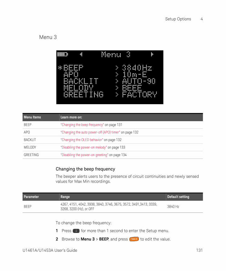
Setup Options 4
Menu 3
Changing the beep frequency
The beeper alerts users to the presence of circuit continuities and newly sensed values for Max Min recordings.
To change the beep frequency:
1 Press for more than 1 second to enter the Setup menu.
2 Browse to Menu 3 > BEEP, and press to edit the value.
Menu Items Learn more on:
BEEP “Changing the beep frequency” on page 131
APO “Changing the auto power-off (APO) timer” on page 132
BACKLIT “Changing the OLED behavior” on page 132
MELODY “Disabling the power-on melody” on page 133
GREETING “Disabling the power-on greeting” on page 134
Parameter Range Defaul t setting
BEEP4267, 4151, 4042, 3938, 3840, 3746, 3675, 3572, 3491,3413, 3339, 3268, 3200 (Hz), or OFF
3840 Hz
U1461A/U1453A User’s Guide 131
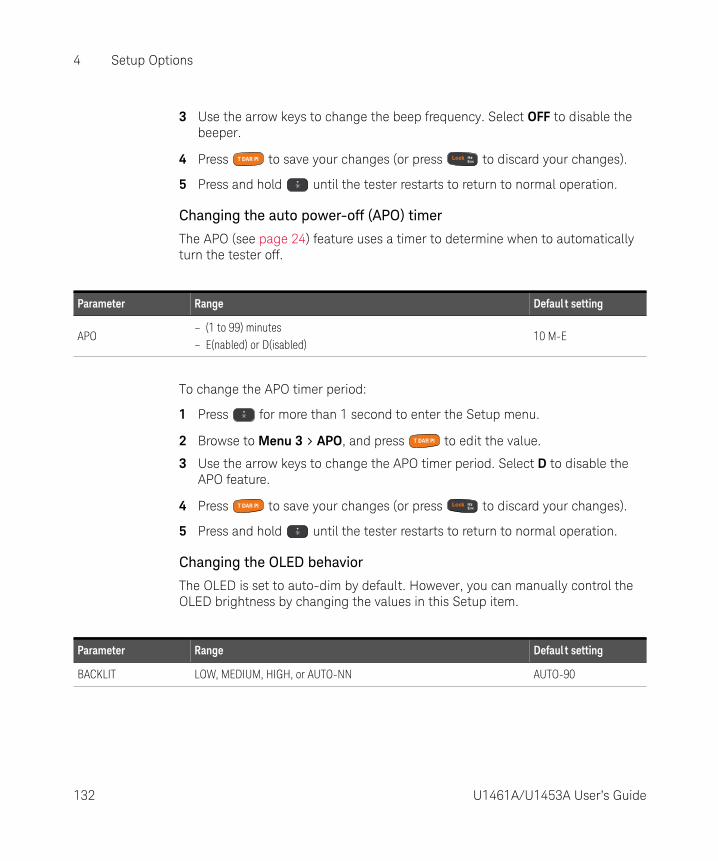
4 Setup Options
3 Use the arrow keys to change the beep frequency. Select OFF to disable the beeper.
4 Press to save your changes (or press to discard your changes).
5 Press and hold until the tester restarts to return to normal operation.
Changing the auto power-off (APO) timer
The APO (see page 24) feature uses a timer to determine when to automatically turn the tester off.
To change the APO timer period:
1 Press for more than 1 second to enter the Setup menu.
2 Browse to Menu 3 > APO, and press to edit the value.
3 Use the arrow keys to change the APO timer period. Select D to disable the APO feature.
4 Press to save your changes (or press to discard your changes).
5 Press and hold until the tester restarts to return to normal operation.
Changing the OLED behavior
The OLED is set to auto-dim by default. However, you can manually control the OLED brightness by changing the values in this Setup item.
Parameter Range Defaul t setting
APO– (1 to 99) minutes– E(nabled) or D(isabled)
10 M-E
Parameter Range Defaul t setting
BACKLIT LOW, MEDIUM, HIGH, or AUTO-NN AUTO-90
132 U1461A/U1453A User’s Guide
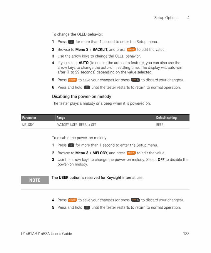
Setup Options 4
To change the OLED behavior:
1 Press for more than 1 second to enter the Setup menu.
2 Browse to Menu 3 > BACKLIT, and press to edit the value.
3 Use the arrow keys to change the OLED behavior.
4 If you select AUTO (to enable the auto-dim feature), you can also use the arrow keys to change the auto-dim settling time. The display will auto-dim after (1 to 99 seconds) depending on the value selected.
5 Press to save your changes (or press to discard your changes).
6 Press and hold until the tester restarts to return to normal operation.
Disabling the power-on melody
The tester plays a melody or a beep when it is powered on.
To disable the power-on melody:
1 Press for more than 1 second to enter the Setup menu.
2 Browse to Menu 3 > MELODY, and press to edit the value.
3 Use the arrow keys to change the power-on melody. Select OFF to disable the power-on melody.
4 Press to save your changes (or press to discard your changes).
5 Press and hold until the tester restarts to return to normal operation.
Parameter Range Defaul t setting
MELODY FACTORY, USER, BEEE, or OFF BEEE
NOTEThe USER option is reserved for Keysight internal use.
U1461A/U1453A User’s Guide 133

4 Setup Options
Disabling the power-on greeting
The tester displays the Keysight logo when it is powered on.
To disable the power on greeting:
1 Press for more than 1 second to enter the Setup menu.
2 Browse to Menu 3 > GREETING, and press to edit the value.
3 Use the arrow keys to change the power-on greeting. Select OFF to disable the power-on greeting.
4 Press to save your changes (or press to discard your changes).
5 Press and hold until the tester restarts to return to normal operation.
Parameter Range Defaul t setting
GREETING FACTORY, USER, or OFF FACTORY
NOTEThe USER option is reserved for Keysight internal use.
134 U1461A/U1453A User’s Guide

Setup Options 4
Menu 4
Changing the baud rate
This setting changes the baud rate for remote communications with a PC.
To change the baud rate:
1 Press for more than 1 second to enter the Setup menu.
2 Browse to Menu 4 > BAUD, and press to edit the value.
Menu Items Learn more on:
BAUD “Changing the baud rate” on page 135
DATA BIT “Changing the data bits” on page 136
PARITY “Changing the parity check” on page 136
ECHO “Enabling the echo feature” on page 137
PRINT “Enabling the print feature” on page 137
Parameter Range Defaul t setting
BAUD (9600 or 19200) bits/second 9600
U1461A/U1453A User’s Guide 135
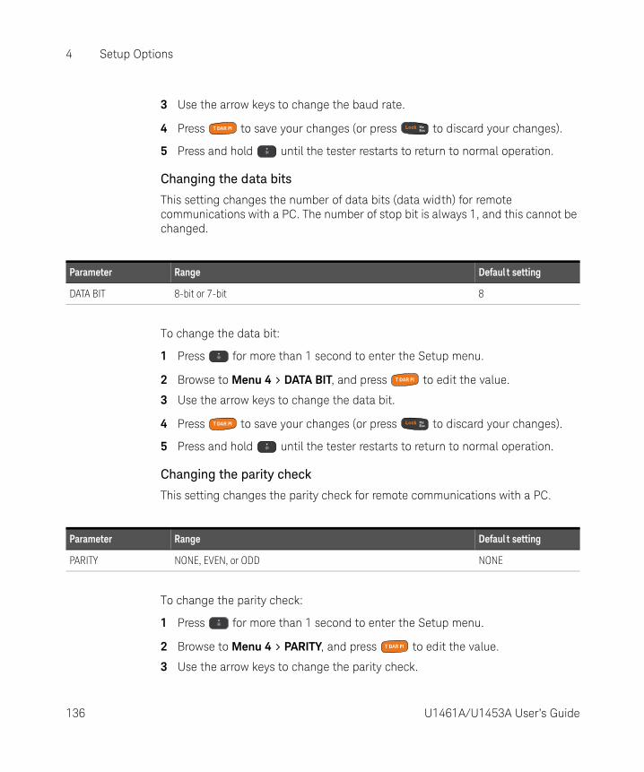
4 Setup Options
3 Use the arrow keys to change the baud rate.
4 Press to save your changes (or press to discard your changes).
5 Press and hold until the tester restarts to return to normal operation.
Changing the data bits
This setting changes the number of data bits (data width) for remote communications with a PC. The number of stop bit is always 1, and this cannot be changed.
To change the data bit:
1 Press for more than 1 second to enter the Setup menu.
2 Browse to Menu 4 > DATA BIT, and press to edit the value.
3 Use the arrow keys to change the data bit.
4 Press to save your changes (or press to discard your changes).
5 Press and hold until the tester restarts to return to normal operation.
Changing the parity check
This setting changes the parity check for remote communications with a PC.
To change the parity check:
1 Press for more than 1 second to enter the Setup menu.
2 Browse to Menu 4 > PARITY, and press to edit the value.
3 Use the arrow keys to change the parity check.
Parameter Range Defaul t setting
DATA BIT 8-bit or 7-bit 8
Parameter Range Defaul t setting
PARITY NONE, EVEN, or ODD NONE
136 U1461A/U1453A User’s Guide

Setup Options 4
4 Press to save your changes (or press to discard your changes).
5 Press and hold until the tester restarts to return to normal operation.
Enabling the echo feature
When the echo feature is enabled, the tester echoes (returns) all the characters it receives when it is connected to a remote PC.
To enable the echo feature:
1 Press for more than 1 second to enter the Setup menu.
2 Browse to Menu 4 > ECHO, and press to edit the value.
3 Use the arrow keys to enable the echo feature.
4 Press to save your changes (or press to discard your changes).
5 Press and hold until the tester restarts to return to normal operation.
Enabling the print feature
When the print feature is enabled, the tester will print out the measured data when the measuring cycle is complete. The tester will automatically send new data to the remote PC host continuously. The tester does not accept any commands from the PC host when this feature is enabled.
Parameter Range Defaul t setting
ECHO OFF or ON OFF
Parameter Range Defaul t setting
PRINT OFF or ON OFF
U1461A/U1453A User’s Guide 137

4 Setup Options
To enable the print feature:
1 Press for more than 1 second to enter the Setup menu.
2 Browse to Menu 4 > PRINT, and press to edit the value.
3 Use the arrow keys to enable the print feature.
4 Press to save your changes (or press to discard your changes).
5 Press and hold until the tester restarts to return to normal operation.
138 U1461A/U1453A User’s Guide

Setup Options 4
Menu 5
Enabling dual display for voltage and current measurements
This setting is used to enable dual display for voltage and current measurements. The AC+DC measurement will be shown on the secondary display.
Menu Items Learn more on:
REVISION -
S/N -
DUAL DC+AC “Enabling dual display for voltage and current measurements” on page 139
ALERT HORN “Changing the alert indicators” on page 140
CONTINUITY “Changing the continuity alert” on page 140
Parameter Range Defaul t setting
DUAL DC+AC YES or NO YES
U1461A/U1453A User’s Guide 139

4 Setup Options
To enable dual display:
1 Press for more than 1 second to enter the Setup menu.
2 Browse to Menu 5 > DUAL DC+AC, and press to edit the value. Select NO to disable the dual display.
3 Use the arrow keys to enable the dual display.
4 Press to save your changes (or press to discard your changes).
5 Press and hold until the tester restarts to return to normal operation.
Changing the alert indicators
The tester’s audible and visual alerts users to the presence of circuit continuities (see page 84) and values exceeding the Limit values set (see page 84).
To change the alert indicators:
1 Press for more than 1 second to enter the Setup menu.
2 Browse to Menu 5 > ALERT HORN, and press to edit the value.
3 Use the arrow keys to change the alert indicators. Select OFF to disable either the beeper, the red LED, or both alert indicators.
4 Press to save your changes (or press to discard your changes).
5 Press and hold until the tester restarts to return to normal operation.
Changing the continuity alert
This setting is used with continuity tests (see page 84). The tester will beep to alert users to the presence of circuit continuities for short or open circuits.
Parameter Range Defaul t setting
ALERT HORN BEE&LED, OFF&LED, BEE&OFF, OFF&OFF BEE&LED
140 U1461A/U1453A User’s Guide

Setup Options 4
To change the continuity alert:
1 Press for more than 1 second to enter the Setup menu.
2 Browse to Menu 5 > CONTINUITY, and press to edit the value.
3 Use the arrow keys to change the continuity alert. Select D to disable the continuity alert for either the SHORT, OPEN, or TONE alerts.
4 Press to save your changes (or press to discard your changes).
5 Press and hold until the tester restarts to return to normal operation.
Menu 6
Parameter Range Defaul t setting
CONTINUITY– SHORT, OPEN, or TONE– D(isabled) or E(nabled)
SHORT-E
Menu Items Learn more on:
DEFAULT “Resetting the tester’s Setup options” on page 142
BATTERY “Changing the battery type” on page 142
MIN-Hz “Changing the minimum measurable frequency” on page 143
U1461A/U1453A User’s Guide 141
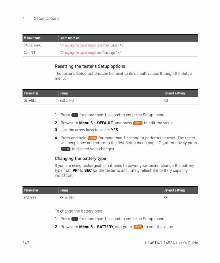
4 Setup Options
Resetting the tester’s Setup options
The tester’s Setup options can be reset to its default values through the Setup menu.
1 Press for more than 1 second to enter the Setup menu.
2 Browse to Menu 6 > DEFAULT, and press to edit the value.
3 Use the arrow keys to select YES.
4 Press and hold for more than 1 second to perform the reset. The tester will beep once and return to the first Setup menu page. Or, alternatively press
to discard your changes.
Changing the battery type
If you are using rechargeable batteries to power your tester, change the battery type from PRI to SEC for the tester to accurately reflect the battery capacity indication.
To change the battery type:
1 Press for more than 1 second to enter the Setup menu.
2 Browse to Menu 6 > BATTERY, and press to edit the value.
CABLE km/C “Changing the cable length scale” on page 143
CL-UNIT “Changing the cable length unit” on page 144
Menu Items Learn more on:
Parameter Range Defaul t setting
DEFAULT YES or NO NO
Parameter Range Defaul t setting
BATTERY PRI or SEC PRI
142 U1461A/U1453A User’s Guide

Setup Options 4
3 Use the arrow keys to change the battery type.
4 Press to save your changes (or press to discard your changes).
5 Press and hold until the tester restarts to return to normal operation.
Changing the minimum measurable frequency
This setting is used with frequency tests (see page 79). Changing the minimum measurable frequency will influence the measurement rates for frequency, duty cycle, and pulse width measurements. The typical measurement rate as defined in the specification is based on a minimum measurable frequency of 10 Hz.
To change the minimum measurable frequency:
1 Press for more than 1 second to enter the Setup menu.
2 Browse to Menu 6 > MIN-Hz, and press to edit the value.
3 Use the arrow keys to change the minimum measurable frequency.
4 Press to save your changes (or press to discard your changes).
5 Press and hold until the tester restarts to return to normal operation.
Changing the cable length scale
This setting is used with capacitance measurements (see page 91). Change the unit (Meter of Feet) of the cable length display.
Parameter Range Defaul t setting
MIN-Hz 0.5 Hz or 10 Hz 0.5 Hz
Parameter Range Defaul t setting
CABLE km/C– (1 to 99) nF– D(isabled) or E(nabled)
40 nF-E
U1461A/U1453A User’s Guide 143
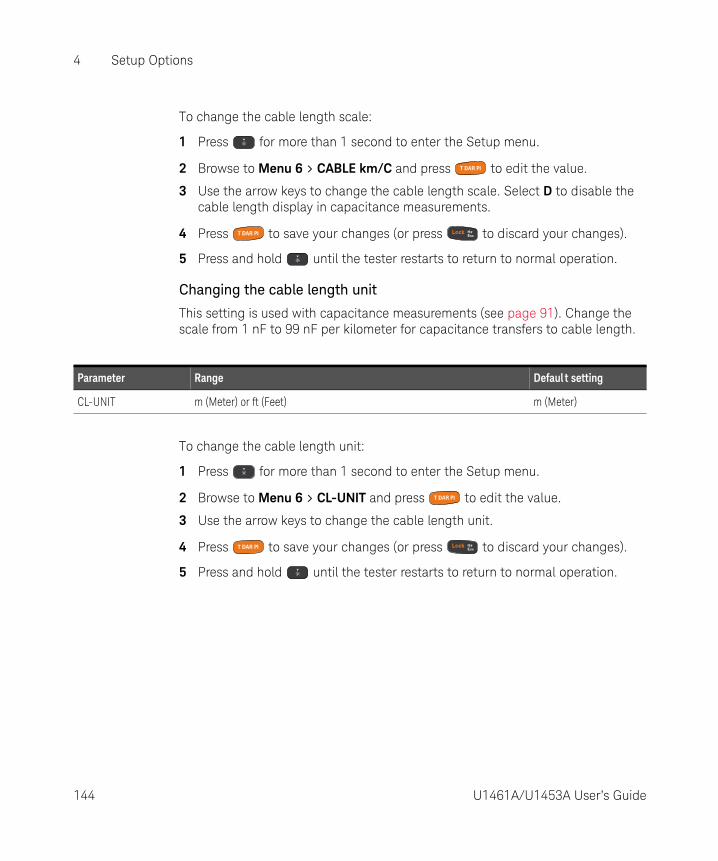
4 Setup Options
To change the cable length scale:
1 Press for more than 1 second to enter the Setup menu.
2 Browse to Menu 6 > CABLE km/C and press to edit the value.
3 Use the arrow keys to change the cable length scale. Select D to disable the cable length display in capacitance measurements.
4 Press to save your changes (or press to discard your changes).
5 Press and hold until the tester restarts to return to normal operation.
Changing the cable length unit
This setting is used with capacitance measurements (see page 91). Change the scale from 1 nF to 99 nF per kilometer for capacitance transfers to cable length.
To change the cable length unit:
1 Press for more than 1 second to enter the Setup menu.
2 Browse to Menu 6 > CL-UNIT and press to edit the value.
3 Use the arrow keys to change the cable length unit.
4 Press to save your changes (or press to discard your changes).
5 Press and hold until the tester restarts to return to normal operation.
Parameter Range Defaul t setting
CL-UNIT m (Meter) or ft (Feet) m (Meter)
144 U1461A/U1453A User’s Guide
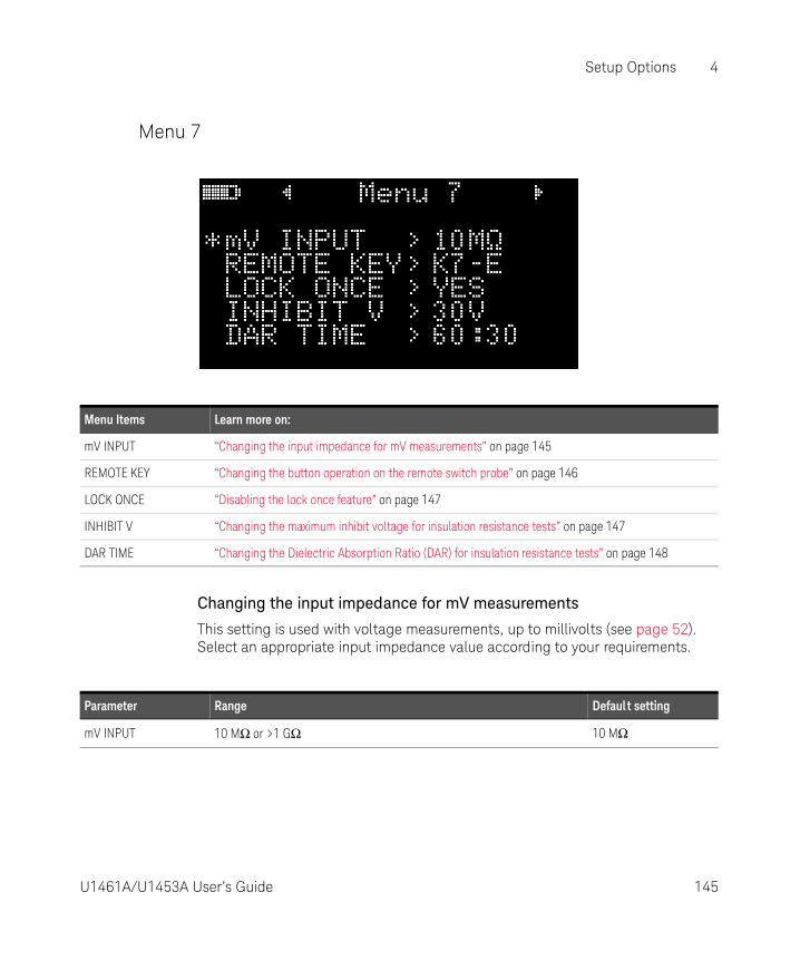
Setup Options 4
Menu 7
Changing the input impedance for mV measurements
This setting is used with voltage measurements, up to millivolts (see page 52). Select an appropriate input impedance value according to your requirements.
Menu Items Learn more on:
mV INPUT “Changing the input impedance for mV measurements” on page 145
REMOTE KEY “Changing the button operation on the remote switch probe” on page 146
LOCK ONCE “Disabling the lock once feature” on page 147
INHIBIT V “Changing the maximum inhibit voltage for insulation resistance tests” on page 147
DAR TIME “Changing the Dielectric Absorption Ratio (DAR) for insulation resistance tests” on page 148
Parameter Range Defaul t setting
mV INPUT 10 MΩ or >1 GΩ 10 MΩ
U1461A/U1453A User’s Guide 145
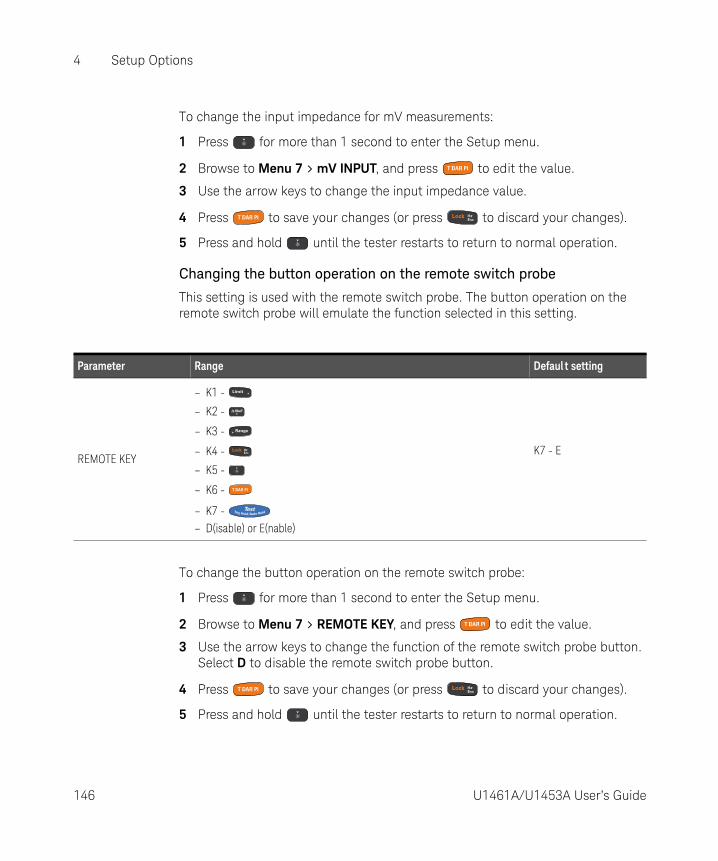
4 Setup Options
To change the input impedance for mV measurements:
1 Press for more than 1 second to enter the Setup menu.
2 Browse to Menu 7 > mV INPUT, and press to edit the value.
3 Use the arrow keys to change the input impedance value.
4 Press to save your changes (or press to discard your changes).
5 Press and hold until the tester restarts to return to normal operation.
Changing the button operation on the remote switch probe
This setting is used with the remote switch probe. The button operation on the remote switch probe will emulate the function selected in this setting.
To change the button operation on the remote switch probe:
1 Press for more than 1 second to enter the Setup menu.
2 Browse to Menu 7 > REMOTE KEY, and press to edit the value.
3 Use the arrow keys to change the function of the remote switch probe button. Select D to disable the remote switch probe button.
4 Press to save your changes (or press to discard your changes).
5 Press and hold until the tester restarts to return to normal operation.
Parameter Range Defaul t setting
REMOTE KEY
– K1 -
– K2 -
– K3 -
– K4 -
– K5 -
– K6 -
– K7 - – D(isable) or E(nable)
K7 - E
146 U1461A/U1453A User’s Guide

Setup Options 4
Disabling the lock once feature
This setting is used with insulation resistance tests (see page 67) and earth-bond resistance measurements (see page 67). By default, the tester will reset the
locked status when the test is stopped by pressing .
If you disable this feature, you will need to press to unlock the tester, even if the test has already stopped.
To disable the lock once feature:
1 Press for more than 1 second to enter the Setup menu.
2 Browse to Menu 7 > LOCK ONCE, and press to edit the value.
3 Use the arrow keys to select NO.
4 Press to save your changes (or press to discard your changes).
5 Press and hold until the tester restarts to return to normal operation.
Changing the maximum inhibit voltage for insulation resistance tests
This setting is used with insulation resistance tests (see page 67). The tester will not perform the insulation resistance test if it detects that the external voltage exceeds the inhibit voltage value set here.
To change the maximum inhibit voltage:
1 Press for more than 1 second to enter the Setup menu.
2 Browse to Menu 7 > INHIBIT V, and press to edit the value.
Parameter Range Defaul t setting
LOCK ONCE YES or NO YES
Parameter Range Defaul t setting
INHIBIT V 30 V, 50 V, or 75 V 75 V
U1461A/U1453A User’s Guide 147

4 Setup Options
3 Use the arrow keys to change the value of the inhibit voltage.
4 Press to save your changes (or press to discard your changes).
5 Press and hold until the tester restarts to return to normal operation.
Changing the Dielectric Absorption Ratio (DAR) for insulation resistance tests
This setting is used with insulation resistance tests (see page 67). The tester performs the DAR test using the ratio set here.
To change the DAR ratio:
1 Press for more than 1 second to enter the Setup menu.
2 Browse to Menu 7 > DAR TIME, and press to edit the value.
3 Use the arrow keys to change the value of the DAR ratio.
4 Press to save your changes (or press to discard your changes).
5 Press and hold until the tester restarts to return to normal operation.
Parameter Range Defaul t setting
DAR TIME 60:30 or 60:15 (seconds) 60:30 (seconds)
148 U1461A/U1453A User’s Guide

Setup Options 4
Menu 8
Changing the insulation resistance test voltage
This setting is used with insulation resistance tests (see page 67). Select U(ser) to manually change the test voltage value for insulation resistance tests.
Menu Items Learn more on:
IR: 50 V
“Changing the insulation resistance test voltage” on page 149
IR: 100 V
IR: 250 V
IR: 500 V
IR: 1000 V
ParameterRange
F(actory) U(ser)[a]
IR: 50 V 50 V 10 V to 60 V
IR: 100 V 100 V 10 V to 120 V
IR: 250 V 250 V 10 V to 300 V
U1461A/U1453A User’s Guide 149

4 Setup Options
To change the insulation resistance test voltage:
1 Press for more than 1 second to enter the Setup menu.
2 Browse to Menu 8, select the desired insulation resistance test voltage (IR: 50 V, IR: 100 V, IR: 250 V, IR: 500 V, or IR: 1000 V) and press to edit the value.
3 Select U and use the arrow keys to change the test voltage.
4 Press to save your changes (or press to discard your changes).
5 Press and hold until the tester restarts to return to normal operation.
Menu 9
IR: 500 V 500 V 10 V to 600 V
IR: 1000 V 1000 V 10 V to 1100 V
[a] Minimum increment of 1 V between each subsequent value.
ParameterRange
F(actory) U(ser)[a]
150 U1461A/U1453A User’s Guide

Setup Options 4
Changing the insulation resistance and earth-bond resistance test period
This setting is used with insulation resistance tests (see page 67) or earth-bond resistance measurements (see page 67). The tester performs the test over the timed period defined in this setting.
To change the insulation resistance and earth-bond resistance test period:
1 Press for more than 1 second to enter the Setup menu.
2 Browse to Menu 9 > TEST TIME, and press to edit the value.
3 Use the arrow keys to change the test period.
4 Press to save your changes (or press to discard your changes).
5 Press and hold until the tester restarts to return to normal operation.
Changing the scan signal dwelling time
This setting is used with insulation resistance tests (see page 67). The scan signal will “dwell” in the present step for the length of time stated in the scan dwelling time before incrementing to the next step.
Menu Items Learn more on:
TEST TIME “Changing the insulation resistance and earth-bond resistance test period” on page 151
SCAN TIME “Changing the scan signal dwelling time” on page 151
SCAN STEP “Changing the scan signal number of steps” on page 152
RAMP STEP “Changing the ramp signal number of steps” on page 153
TRIP mA “Changing the trip current value” on page 153
Parameter Range Defaul t setting
TEST TIME 00:05 to 59:59 01:00
U1461A/U1453A User’s Guide 151

4 Setup Options
To change the scan signal dwelling time:
1 Press for more than 1 second to enter the Setup menu.
2 Browse to Menu 9 > SCAN TIME, and press to edit the value.
3 Use the arrow keys to change the dwelling time.
4 Press to save your changes (or press to discard your changes).
5 Press and hold until the tester restarts to return to normal operation.
Changing the scan signal number of steps
This setting is used with insulation resistance tests (see page 67). The increment of each step in the scan signal will be the amplitude end position divided by the number of steps. Each step should be set to greater than 10 V and the last step is equal to or less than the test voltage setting.
To change the scan signal number of steps:
1 Press for more than 1 second to enter the Setup menu.
2 Browse to Menu 9 > SCAN STEP, and press to edit the value.
3 Use the arrow keys to change the number of steps.
4 Press to save your changes (or press to discard your changes).
5 Press and hold until the tester restarts to return to normal operation.
Parameter Range Defaul t setting
SCAN TIME (1 to 99) seconds 10 seconds
Parameter Range Defaul t setting
SCAN STEP (1 to 100) steps 5 steps
152 U1461A/U1453A User’s Guide

Setup Options 4
Changing the ramp signal number of steps
This setting is used with insulation resistance tests (see page 67). The increment of each step in the ramp signal will be the amplitude end position divided by the number of steps. For example, a 50 V amplitude end position divided by 100 steps gives an increment of 0.5 V per step.
To change the ramp signal number of steps:
1 Press for more than 1 second to enter the Setup menu.
2 Browse to Menu 9 > RAMP STEP, and press to edit the value.
3 Use the arrow keys to change the number of steps.
4 Press to save your changes (or press to discard your changes).
5 Press and hold until the tester restarts to return to normal operation.
Changing the trip current value
This setting is used with insulation resistance tests (see page 67). Set the current value for tripping the insulation resistance test (trip by leakage current/breakdown current).
To change the trip current value:
1 Press for more than 1 second to enter the Setup menu.
2 Browse to Menu 9 > TRIP mA, and press to edit the value.
3 Use the arrow keys to change the trip current.
Parameter Range Defaul t setting
RAMP STEP (1 to 1000) steps 100 steps
Parameter Range Defaul t setting
TRIP mA (0.001 to 1.500) mA 1.000 mA
U1461A/U1453A User’s Guide 153

4 Setup Options
4 Press to save your changes (or press to discard your changes).
5 Press and hold until the tester restarts to return to normal operation.
Menu 10
NOTEMenu 10 is for model U1461A only.
Menu Items Learn more on:
T-TYPE “Changing the thermocouple type” on page 155
T-UNIT “Changing the temperature unit” on page 155
LPF “Enabling the low-pass filter” on page 156
mA SCALE “Changing the % (mA) scale range” on page 157
% & ms “Enabling the (+ or –) duty cycle and pulse width display” on page 157
154 U1461A/U1453A User’s Guide
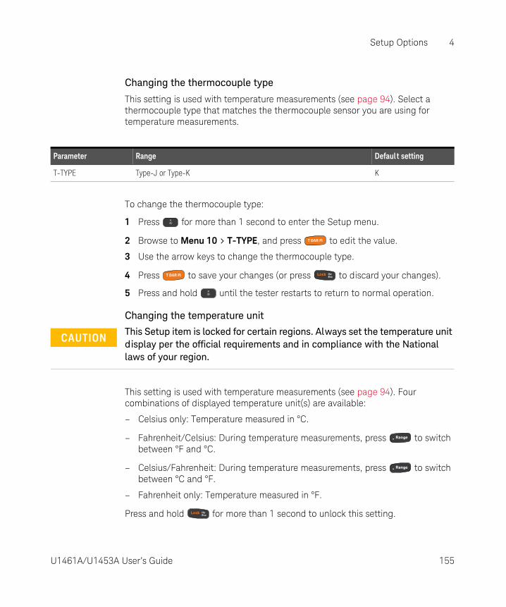
Setup Options 4
Changing the thermocouple type
This setting is used with temperature measurements (see page 94). Select a thermocouple type that matches the thermocouple sensor you are using for temperature measurements.
To change the thermocouple type:
1 Press for more than 1 second to enter the Setup menu.
2 Browse to Menu 10 > T-TYPE, and press to edit the value.
3 Use the arrow keys to change the thermocouple type.
4 Press to save your changes (or press to discard your changes).
5 Press and hold until the tester restarts to return to normal operation.
Changing the temperature unit
This setting is used with temperature measurements (see page 94). Four combinations of displayed temperature unit(s) are available:
– Celsius only: Temperature measured in °C.
– Fahrenheit/Celsius: During temperature measurements, press to switch between °F and °C.
– Celsius/Fahrenheit: During temperature measurements, press to switch between °C and °F.
– Fahrenheit only: Temperature measured in °F.
Press and hold for more than 1 second to unlock this setting.
Parameter Range Defaul t setting
T-TYPE Type-J or Type-K K
CAUTIONThis Setup item is locked for certain regions. Always set the temperature unit display per the official requirements and in compliance with the National laws of your region.
U1461A/U1453A User’s Guide 155

4 Setup Options
To change the temperature unit:
1 Press for more than 1 second to enter the Setup menu.
2 Browse to Menu 10 > T-UNIT. Press and hold for more than 1 second to
unlock this setting, then press to edit the value.
3 Use the arrow keys to change the temperature unit.
4 Press to save your changes (or press to discard your changes).
5 Press and hold until the tester restarts to return to normal operation.
Enabling the low-pass filter
This setting is used to enable the low-pass filter to filter out higher frequencies with (AC/DC path) V, mV, μA, or mA measurements. The symbol is shown during these measurements.
To enable the filter:
1 Press for more than 1 second to enter the Setup menu.
2 Browse to Menu 10 > LPF, and press to edit the value.
3 Use the arrow keys to enable the filter.
4 Press to save your changes (or press to discard your changes).
5 Press and hold until the tester restarts to return to normal operation.
Parameter Range Defaul t setting
T-UNIT °C, °F/°C, °C/°F, or °F °C
Parameter Range Defaul t setting
LPF ON or OFF OFF
156 U1461A/U1453A User’s Guide

Setup Options 4
Changing the % (mA) scale range
This setting is used with % (mA) scale current measurements (see page 78). The tester converts DC current measurements to a percentage scale readout of 0% to 100% based on the selected range in this menu. For example, a 25% readout represents a DC current of 8 mA on the 4-20 mA % scale, or a DC current of 5 mA on the 0-20 mA % scale.
To change the % (mA) scale range:
1 Press for more than 1 second to enter the Setup menu.
2 Browse to Menu 10 > mA SCALE, and press to edit the value.
3 Use the arrow keys to change the % scale range. Select D to disable the mA scale readout.
4 Press to save your changes (or press to discard your changes).
5 Press and hold until the tester restarts to return to normal operation.
Enabling the (+ or –) duty cycle and pulse width display
This setting is used with frequency measurements (see page 79). Enabling this feature will allow you to display (+ or –) duty cycle and pulse width along with frequency for voltage or current measurements.
To enable the duty cycle and pulse width display:
1 Press for more than 1 second to enter the Setup menu.
2 Browse to Menu 10 > % & ms, and press to edit the value.
Parameter Range Defaul t setting
mA SCALE– 4-20 mA or 0-20 mA– D(isable) or E(nable)
4-20 mA-D
Parameter Range Defaul t setting
% & ms– +CYCLE or –CYCLE– D(isable) or E(nable)
+CYCLE-D
U1461A/U1453A User’s Guide 157

4 Setup Options
3 Use the arrow keys to change the duty cycle and pulse width settings. Select E to enable the duty cycle and pulse width display.
4 Press to save your changes (or press to discard your changes).
5 Press and hold until the tester restarts to return to normal operation.
Menu 11
NOTEMenu 11 is only for:
– Model U1461A (EBR and μA mA function only)
– Model U1453A (EBR function only)
Menu Items Learn more on:
LEAD ALERT “Changing the lead alert setting” on page 159
158 U1461A/U1453A User’s Guide

Setup Options 4
Changing the lead alert setting
This setting is used to trigger an alert for the user to change the test lead connection to the correct terminals before the measurement takes place. You can change the lead alert setting and its duration. The lead alert will sound whenever you switch to a mode that requires the test leads to be repositioned on the tester. This alert will take the form of a beeping sound and caution titled
that will flash on the top portion of the primary display.
Parameter Range Defaul t setting
LEAD ALERT NONE, USER, or AUTO-NN AUTO-03[a]
[a] The “03” value corresponds to a warning duration of 3 seconds
U1461A/U1453A User’s Guide 159

4 Setup Options
There are three available beep settings for the lead alert.
To change the lead alert settings:
1 Press for more than 1 second to enter the Setup menu.
2 Browse to Menu 11 > LEAD ALERT, and press to edit the lead alert setting.
3 Use the and keys to select the desired beep setting.
– Under the AUTO-NN setting, use the and keys to navigate to the NN section, then use the and keys to select the desired lead alert duration.
4 Press to save your changes (or press to discard your changes).
Press and hold until the meter restarts to return to normal operation.
Beep setting Description
NONE No beep/ warning
USERA continuous beep/ warning
The beep/ warning will stop when:– Any softkey is pressed
AUTO-NN
A user-defined setting for the beep/ warning– You can manually set the beep/warning duration from 01 to 99 seconds
The beep/ warning will stop when:
– Any softkey is pressed– The duration set by the user is completed
NOTEAfter a firmware update, if the LEAD ALERT setting is shown as AUTO-00, restore the setting to the factory default. Refer to “Resetting the tester’s Setup options” on page 142 for more details.
160 U1461A/U1453A User’s Guide

U1461A Insulation Multimeter/U1453A Insulation TesterUser’s Guide
5 Characteristics and Specifications
For the characteristics and specifications of the U1461A Insulation Multimeter/U1453A Insulation Tester, refer to the datasheet at http://literature.cdn.keysight.com/litweb/pdf/5991-4290EN.pdf.
161

5 Characteristics and Specifications
THIS PAGE HAS BEEN INTENTIONALLY LEFT BLANK.
162 U1461A/U1453A User’s Guide

This information is subject to change without notice. Always refer to the Keysight website for the latest revision.
© Keysight Technologies 2014–2016 Edition 9, November 18, 2016
Printed in Malaysia
*U1461-90003*U1461-90003 www.keysight.com