kharkov national university of radio electronics, design automation department dsd 2003, turkey,...
Post on 21-Dec-2015
215 views
TRANSCRIPT

1Kharkov National University of Radio Electronics, Design Automation Department
DSD 2003, Turkey, Antaliya, September 1-6
Professor Vladimir I. HAHANOVDoctor of Sciences (Engineering), IEEE memberChief-Editor of Journals“Radioelectronics & Informatics”
“Automated Control Systems & Devices”,
Gowher Malik :Student of Masters Program ‘Computer Systems and Networks’ at’ Kharkov National University of RadioElectronics’. It consists of two institutes and 7 faculties, 8000 students, 100 professors and doctors of science, 400 PhD and professor assistants, more than 900 computers in laboratories.
14, Lenin Avenue, Kharkov, 61166, UkrainePhone (+380)-572-70 21 326, E-mail:[email protected] space: Digital Systems Testing and Testable Design, Fault Simulation and Test Generation for RTL-Systems
.

2Kharkov National University of Radio Electronics, Design Automation Department
DSD 2003, Turkey, Antaliya, September 1-6
Design effort
Design verification
70%
Design development
30%
Number of engineers
Design verification
66%
Design development
33%
Code of design
Design verification
80%
Design development
20%
Actuality of digital systems testingFor multi-million gate ASICs, reusable Intellectual Property (IP), and System-on-Chip (SoC) designs, verification consumes 70% of the design effort.The number of verification engineers is usually twice the number of RTL designers. The testbenches code makes up to 80 % of the total design code volume.
[Bergeron Janick. Writing testbenches: functional verification of HDL models.– Boston: Kluwer Academic Publishers.– 2001.– 354 c.]

3Kharkov National University of Radio Electronics, Design Automation Department
DSD 2003, Turkey, Antaliya, September 1-6
Aldec: Active HDL, Riviera Cadence: VerifaultAltera: MAX+PLUS II Xilinx: Foundation 2.1 Synopsys: FPGA Express Synthesis, BSD Compiler, TetraMAXActel: ActelDeskTopSynplicity: VeriBest, SynplifyAsset: ScanWorks boundary scan (IEEE 1149.1) system (Test DevelopmentStation, Programming Station, Manufacturing Station, Diagnostic&Repair Station)Virage Logic: Embed-It!, Architect, Integrator, Automated Characterization(automated memory development tools)Logic Vision: Embedded Test, ET Verify, LV TestStationMentor Graphics: FlexTest, QuickFaultSyntest: TurboBIST-Memory, TurboBist–LogicTurboFault, TurboFault, SynTestSimucad: Verilog HDL Logic Simulation, HyperFaultFault Simulation (logic simulation, fault simulation)
Corporations – Leaders in Design and Test area

4Kharkov National University of Radio Electronics, Design Automation Department
DSD 2003, Turkey, Antaliya, September 1-6
Test Systems Lanuage Support Description
LevelProcessing Time (H/x1000gates)
Output Data Platform
TurboFault, SYNTEST
Verilog Gate Level NetList
RTL, Gate level, UDP
1,5 / 100 VHDL, Verilog,
TestBench Solaris, SunOS, HP
Memory TurboBIST, SYNTEST
VHDL, VerilogRTL, Gate
level4,5 / 4900
VHDL, Verilog, TestBench
Solaris, SunOS, Windows NT
TurboScan, SYNTEST
Verilog RTL 6,5 / 700 WGL, VHDL,
Verilog TestBench Solaris, SunOS, Windows NT
TurboBIST-Logic, SYNTEST
VHDL, Verilog RTL 17,5 / 4900 WGL, VHDL,
Verilog TestBench Solaris, SunOS, HP-
(UNIX and Linux)
TetraMAX ATPG, Synopsys
Verilog, VHDL (87 и 93), EDIF
RTL, Gate level
2 / 1800STIL, WGL,
Toshiba TSTL2Solaris, SunOS,
Windows BSD Compiler,
SynopsysVHDL, Verilog,
only RTL RTL –
WGL, VHDL, Verilog TestBench
Solaris, SunOS, Windows
FlexTest, Mentor Graphics
VHDL, Verilog, only RTL
RTL –WGL, Verilog
TestBench Solaris, SunOS
Embedded Test 4.0, LogicVision
VHDL, Verilog, only RTL
RTL, Gate level
–WGL, VHDL,
Verilog TestBench Solaris, SunOS
VeriFault, CadenceVerilog
Behavioral,NetlistRTL, Gate
level2,5 / 200 Verilog TestBench Solaris, SunOS
Silos, SimucadVerilog
Behavioral,NetlistRTL, Gate
level3 / 20 Verilog TestBench
Solaris, SunOS, Windows
Properties of well known Test Systems

5Kharkov National University of Radio Electronics, Design Automation Department
DSD 2003, Turkey, Antaliya, September 1-6 References[1] Hahanov V.I., Babich À.V., Hyduke S.M., Test Generation and Fault Simulation Methods on the Basis of Cubic Algebra for Digital Devices, Proc. Euromicro Symposium on Digital Systems Design, Warsaw, Poland, 2001, 228-235. [2] Semenetz. V., Hahanova I., Hahanov V. Digital systems design using VHDL.- Kharkov.- KNURE.- 2003.- 492 p.[3] Bondarenko M., Krivoulya G., Ryabtcev V., Fradkov S., Hahanov V. Design and testing of computer systems and networks.- Kiev: NMCVO. 2000.- 306 p. [4] Levendel Y.H., Menon P.R., Comparison of fault simulation methods – Treatment of unknown signal values, Journal of Digital Systems. Vol. 4, 1980, 443-459. [5] Abramovici M., Breuer M.A. and Friedman A.D., Digital System Testing and Testable Design.- Computer Science Press, 1998. [6] Ubar R. ,The analysis of diagnostic tests for combinational digital circuits by fault back tracing methods.- Moscow.- Automatica and Telemechanica.- No 8.- 1977.[7] Hahanov V.I., Technical diagnosis for devices of personal conputers.- Kiev: IZMN, 1997)[8] Nierman T.M., Cheng W.–T., Patel J.H. PROOFS: A Fast, Memory Efficient Sequential Circuit Fault Simulator // IEEE Transaction on CAD. – 1992. – vol.11, no. 2. – P. 198–207.[9] Sudhakar M. Reddy, Irith Pomeranz, Xijiang Lin, Nadir Z. Basturkmen. New Procedures for Identifying Undetectable and Redundant Faults In Synchronous Sequential Circuits // 17th IEEE VLSI Test Simposium. – 1999. – P. 476–480.[10] Ruifeng Guo, Irith Pomeranz, Sudhakar M. Reddy. A Fault Simulation Based Test Pattern Generator for Synchronous Sequential Circuits//17th IEEE VLSI Test Simposium.–1999.–P.456–460.

6Kharkov National University of Radio Electronics, Design Automation Department
DSD 2003, Turkey, Antaliya, September 1-6
Purpose is to develop high performance fault simulation method for test generation system of complex digital devices described in HDL.Problems are:1. Investigation of design and test world market.2. Developing deductive theory of fault simulation for RTL described digital systems.3. Developing deductive-parallel fault analysis model.4. Creation of back traced deductive-parallel fault analysis method.5. Developing deductive model of circuit structure analysis.6. Creation of internal circuit model for fault simulation.7. Developing topological deductive-parallel fault simulation.8. Program applications of developed methods and models.9. Integrating fault simulation program with ATPG SIGETEST.10. Testing and verification implemented methods, models and program.
Outlines: Purpose & Problems

7Kharkov National University of Radio Electronics, Design Automation Department
DSD 2003, Turkey, Antaliya, September 1-6
Circuit structure analysis
3
1
214
5
15
6
4
16
7
8
19
2023
10
2611
12
24
13
25
21
22
17
9
28
27
18
5
6
416
7
8
19
20
23
10
2611
12
24
13
25
21
22
17
9
28
27
18
3
1
214
15
1. Searching the reconvergent fan outs for purpose of its deductive-parallel fault simulation.
2. Transforming reconvergent fan out lines into pseudo primary outputs.
3. Representation of circuits model as tree like structure for back-traced fault simulation.

8Kharkov National University of Radio Electronics, Design Automation Department
DSD 2003, Turkey, Antaliya, September 1-6
7
7
1
4
4
5
5
6
6 7
5
4
61
1
1
2
2
1
1
3
3
Model transformation: Circuit – Graph – OR-circuit
1) It is needed for theoretical proof of deductive model consistency for reconvergent fan-out searching.
2) The current equipotential line of fault free circuit becomes vertex of the oriented graph.
3) The vertex model becomes a logical element OR, where the number of inputs is equal to input edges of the current vertex.
4
5
67
2
1
3 3&
&
1 1
2
1
3
9Kharkov National University of Radio Electronics, Design Automation Department
DSD 2003, Turkey, Antaliya, September 1-6
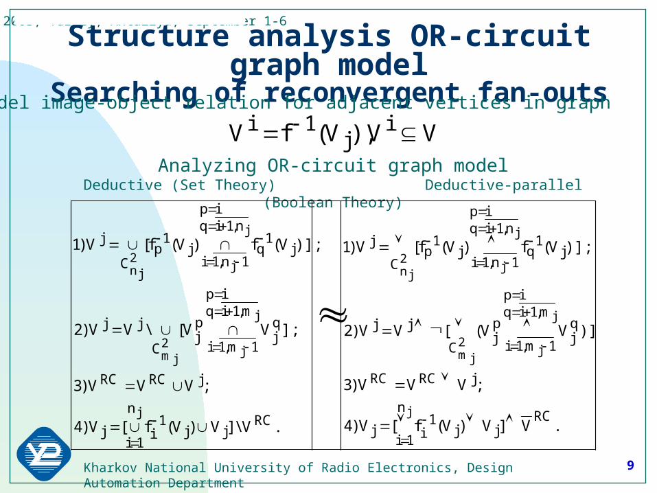
Structure analysis OR-circuit graph modelSearching of reconvergent fan-outs
VV),V(fV ij
1i Model image-object relation for adjacent vertices in graph
Analyzing OR-circuit graph modelDeductive (Set Theory) Deductive-parallel (Boolean Theory)
.V]V)V(f[V)4
;VVV)3
)];VV([VV)2
)];V(f)V(f[V)1
.V\]V)V(f[V)4
;VVV)3
];VV[\VV)2
)];V(f)V(f[V)1
RCjj
1i
n
1ij
jRCRC
qj
m,1iqip
1m,1i
pj
C
jj
j1
q
n,1iqip
1n,1ij
1p
C
j
RCjj
1i
n
1ij
jRCRC
qj
m,1iqip
1m,1i
pj
C
jj
j1
q
n,1iqip
1n,1ij
1p
C
j
j
j
j2
jm
j
j2
jn
j
j
j2
jm
j
j2
jn

10Kharkov National University of Radio Electronics, Design Automation Department
DSD 2003, Turkey, Antaliya, September 1-6
2
3
4
5
6
7
8
9
1
}.9,6,3,2{V;V
};8,6,4,3,1{}2{\}8,6,4,3,2,1{V
};2{)VV(V
};7,5,4,3{}2,1{\}7,5,4,3,2,1{V
};2,1{)VV(V
};6,3,2{V;)VV(V
};5,3,2,1{V;)VV(
)VV()VV(V
};4,2,1{V;)VV(V
};3{V;V
};2{V;V
};1{V;V
99
8
648
7
547
6326
532
31215
4214
33
22
11
}.2,1}2{}2,1{
VVVVVVVVVV 987654321R
Deductive searching sample of reconvergent fan-outs in oriented graph(Vj – list of predecessors, Vi – list of reconvergent fan out)
2
3
4
5
6
7
8
9
1 1
1
1
1
1
1

11Kharkov National University of Radio Electronics, Design Automation Department
DSD 2003, Turkey, Antaliya, September 1-6
3
5
6
84
72
9
1
Flip-flop structure and its graph modelthat is used for RFO searching
Definition: for the synchronous circuits containing FF feedbacks, the loop line is RFO, if this one consists of more then one outgoing arcs and has the nearest line of convergence which doesn’t belong to this feedback loop.
Boolean Normal Form:S2_tmp0=C_tmp0*Q3_tmp0(t-1);Q2_tmp0(t)=!S2_tmp0+(D_tmp0*Q2_tmp0(t-1)); R3_tmp0=!(D_tmp0*Q2_tmp0(t-1));Q3_tmp0(t)=!C_tmp0+(R3_tmp0*Q3_tmp0(t-1));Q(t,0)=!Q3_tmp0(t)+(Q2_tmp0(t)*Q(t-1)).

12Kharkov National University of Radio Electronics, Design Automation Department
DSD 2003, Turkey, Antaliya, September 1-6
10X100001X0010X111110100X
YYXXX
C
54321
FX1
Y5
Y4X2
X3
Set theory model of fault transportation Operates test-vector, multi-valued cubic coverage, output fault list
n – number of cubes; m – number of input lines; k – number of output lines; Sr – fault list on output r of multi output primitive;Sj – input fault list of primitiveTj (Tr) – value of test-vector coordinate;Cij (Cir) – input (output) coordinate value of cubic coverage;
The mostuniversal and basic formula of fault transportation
;k,1r;m,1j;n,1i
;)CT(iZ
)];XC(&)CT[(jX
;)CT(jX
,}T{)]}S(\)S[({S
zirr
xij
xijj
xijj
zr
Xj
Z Xjr

13Kharkov National University of Radio Electronics, Design Automation Department
DSD 2003, Turkey, Antaliya, September 1-6
Boolean model of deductive-parallel fault analysis by truth tableOperates test-vector, cubic coverage, deductive truth table or deductive function
LFT
)F,...F,...,F,F(F ni21
)T,...,T,...,T,T(T kt21
)L,...,L,...,L,L(L kt21
)X,...X,...,X,X(fFiinij2i1iii
,T)]TX(),...,TX(...,
),...TX(),TX[(fFTL
tiitniintjij
2t2i1t1iiitti
.XXXXXX)Y(L
000110101111YXX
111001010000YXX
111YXX
;XXXX)Y(L
101111000010YXX
111101010000YXX
010YXX
212121
2121
21
2121
2121
21
14Kharkov National University of Radio Electronics, Design Automation Department
DSD 2003, Turkey, Antaliya, September 1-6
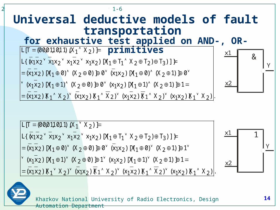
Universal deductive models of fault transportation for exhaustive test applied on AND-, OR-primitives
).XX)(xx()XX)(xx()XX)(xx()XX)(xx(
1)]1X()1X)[(xx(1)]0X()1X)[(xx(
1)]1X()0X)[(xx(0)]0X()0X)[(xx(
)]}T)TXTX)[(xxxxxxxx{(L
)]XX(),11,10,01,00(T[L
2121212121212121
21212121
21212121
3221121212121
21
).XX)(xx()XX)(xx()XX)(xx()XX)(xx(
1)]1X()1X)[(xx(0)]0X()1X)[(xx(
0)]1X()0X)[(xx(0)]0X()0X)[(xx(
)]}T)TXTX)[(xxxxxxxx{(L
)]XX(),11,10,01,00(T[L
2121212121212121
21212121
21212121
3221121212121
21
&
1x1
x1
Y
Y
x2
x2

15Kharkov National University of Radio Electronics, Design Automation Department
DSD 2003, Turkey, Antaliya, September 1-6
Universal deductive parallel simulator(may be used as embedded accelerator)
transport fault vectors through AND-, OR-primitive under any applied binary input vector
D CA N D -0
O R -1 10
11
00
01
X 1
X 2
x 1
x 2
Y
010101111101111011101100101110111110110111001001110110111000
YXXxxOr/And 2121
X1, X2 -vector variables;x1, x2 – Boolean variables;input AND/OR- primitive mode
Table of two test-vector evaluation for parallelsimulation

16Kharkov National University of Radio Electronics, Design Automation Department
DSD 2003, Turkey, Antaliya, September 1-6
The limitations of deductive functions creationStatement 1. Deductive function for binary vector has not inversion on any primitive outputs. Statement 2. Deductive function for binary vector can have inversion on primitive inputs. Statement 3. Deductive function for binary vector can’t have inversion on all primitive inputs.
;ba1)]1b()1a[(ba;ba0)]0b()1a[(ba;ba0)]1b()0a[(ba;ba0)]0b()0a[(ba
.ba1)]1b()1a[(ba;ba1)]0b()1a[(ba;ba1)]1b()0a[(ba;ba0)]0b()0a[(ba
.X0X0)1X()0Y1X(XY
.X1X1)0X()1Y0X(XY
&
1x1
x1
Y
Y
x2
x2
X Y

17Kharkov National University of Radio Electronics, Design Automation Department
DSD 2003, Turkey, Antaliya, September 1-6
Transformations of good primitives into deductive ones under applied binary vectors
210 121 xxxxy
210 021 xxxxy
211 021 xxxxy
211121 xxxxy
211121 xxxxy
211 021 xxxxy
210 121 xxxxy
210 021 xxxxy
AND -FF-DM O R-FF-D MDM

18Kharkov National University of Radio Electronics, Design Automation Department
DSD 2003, Turkey, Antaliya, September 1-6
Reconfiguration of good model into deductive-parallel one
22
23
16
19
11
101
2
3
6
7
22
23
16
19
11
101
2
3
6
7
Input test-vector T=11111110001 and good device model create deductive circuit for simulating fault-vector containing in fault matrix
10111001100230100010000122001010011001900011001100160000100110011000001001011000000010000700000001000600000000100300000000010200000000001123221916111076321M1

19Kharkov National University of Radio Electronics, Design Automation Department
DSD 2003, Turkey, Antaliya, September 1-6
F in d in g th e re c o n v e rg e n t fa n -o u ts in c irc u it
U n d e te c ta b le r e la tiv e lyto re c o n v e rg e n t f a n -o u ts
D e te c ta b le r e la tiv e lyto re c o n v e rg e n t f a n -o u ts
F o rm in g o f u n d e te c ta b le fa u lt l is t
F o rm in g o f d e te c te dfa u lt v e c to r
D e c o m p o s itio n o f th e c irc u ito n tre e -ty p e s tru c tu re
F a u lt s im u la tio n o f re c o n v e rg e n t fa n -o u ts
B a c k tr a c e d s im u la tio n - su p e rp o s itio n p ro c e d u re
6
2
3
4
7
5
8
1
).n4.2]W/)n2.0[(
)n4.0n2.0n
nn]W/)n2.0[(Q
2
2
Back-traced fault simulation strategy:- reconvergent fan-out searching;- fault-free simulation of test-vector;- separation of tree-like structure;- fault simulation of reconvergent fan-outs;- back-traced superposition of tree-like parts;- forming of general detected fault vector.
Computing complexity (n – number of line or gates, W – length of computer word):

20Kharkov National University of Radio Electronics, Design Automation Department
DSD 2003, Turkey, Antaliya, September 1-6
Back-traced fault simulation procedure – superposition of detectable fault vectors of primitives for tree-like structure
2(0)
4(1 )
5 (1 )
1 (0 )
3 (1 )
6 (1 )
7 (0 )
8 (1 )
2
1
34
9(0)
1
&
1&
0LLLLL10.00..11
LLLL10.00....
0LLLLL10.00....
L...0...11L..1..00..L.0.0.....L10..0....
LLLLL987654321
61
61
72
7
83
8434
1234
ji
ji
In the table sign (.) equals to sign empty set.
The condition of superposition is not empty set intersection on connected line j.

21Kharkov National University of Radio Electronics, Design Automation Department
DSD 2003, Turkey, Antaliya, September 1-6
Interpretative model of fault-free and fault analysis
Y
X
F
T
F
T X
F T
YX Y
X
F
T
T X
F T
M F F
0001111
0101011
1000111
1110011
1101110
1011010
0110110
0010010
0011101
0111001
1010101
1100001
1111100
1001000
0100100
0000000
FYXXFS F21
)).X(M...)X(M)X(M(F
))X(M...)X(M)X(M),X(T*F(F)Y(M
k21))X(T*F(
k21F
))X(T*...*)X(T*)X(T*F(F)T*F(F)Y(T k21TXT
Formulas of interpretative model evaluation for (1 - fault free simulation, 2 - fault simulation)
Truth table of fault-free simulation
Internal model of Fault-free simulation
Internal model of fault simulation
22Kharkov National University of Radio Electronics, Design Automation Department
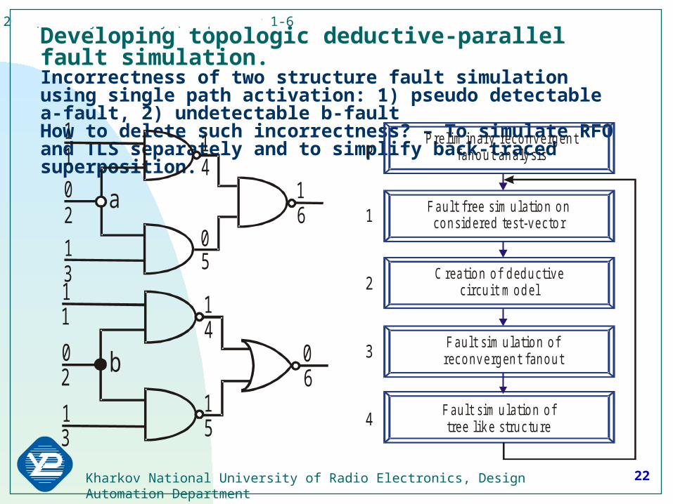
DSD 2003, Turkey, Antaliya, September 1-6Developing topologic deductive-parallel fault simulation.Incorrectness of two structure fault simulation using single path activation: 1) pseudo detectable a-fault, 2) undetectable b-fault How to delete such incorrectness? – To simulate RFO and TLS separately and to simplify back-traced superposition.
Pre lim inary reconvergen t fanou t ana lysis
Fault sim ulation o ftree like struc tu re
C rea tion o f deductive circu it m odel
Fault sim ulation o f reconvergen t fanou t
Fault free sim ulation on considered test-vecto r1
2
3
4
P11
2
3
4
5
60
1
1
0
1a
11
2
4
5
6
3
0
1
1
1
0b

23Kharkov National University of Radio Electronics, Design Automation Department
DSD 2003, Turkey, Antaliya, September 1-6
The basis of topologic simulation
1) Inversion input of deductive element AND forbids fault activation path for all predecessor lines of the mentioned input. 2) All inputs of deductive primitive AND are defined as inverted if primitive have more than one uncomplemented input. 3) Deductive primitive AND activate all predecessor lines faults only on uncomplemented input that must be only one. 4) Deductive primitive OR can’t contain inverted inputs. 5) Reconvergent fan out line is signed as inversion if its fault don’t detect on test-vector. 6) The input or output lines with inversion are interruption condition of fault back tracing trough considered branch of tree like structure. 7) Detected fault of reconvergent fan outs signed by bold point is considered like primary output foe executing fault back tracing. 8) Interpretation of topologic simulation result: equipotent line’s faults that aren’t signed as inversion on deductive model are detected.
24Kharkov National University of Radio Electronics, Design Automation Department
DSD 2003, Turkey, Antaliya, September 1-6
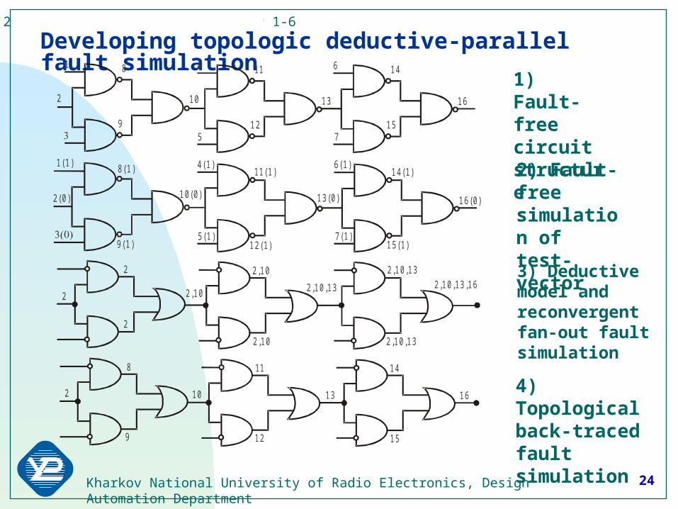
Developing topologic deductive-parallel fault simulation641 14118
1613
15129
102
75
6(1)4(1)1(1)14(1)11 (1)8(1)
16(0)13(0)
15(1)12(1)9(1)
10(0)2(0)
7(1)5(1)
2 ,10
2 ,10
2 ,10 ,13
2 ,10 ,13
2 ,10 ,13
2 ,10 ,13 ,16
2 ,10
2
2
2
14118
1613
15129
102
1) Fault-free circuit structure
2) Fault-free simulation of test-vector
3) Deductive model and reconvergent fan-out fault simulation
4) Topological back-traced fault simulation

25Kharkov National University of Radio Electronics, Design Automation Department
DSD 2003, Turkey, Antaliya, September 1-6
Developing topologic deductive-parallel fault simulation.Interpretation of result: The faults of lines having inversion sign aren’t detected.
11
3
6
7
8
1
1
0
14 9
1 0
110
2
5
0
1
1
1
0
7
8 11
14
5
9
1 0
111
1
0
1
11
2
6
7
8
3
0
1
1
1
0
1 0
11
1) The faults of lines 7, 8 and 11 are detected.
2) The faults of lines 10 and 11 are detected – it have not inversion sign.

26Kharkov National University of Radio Electronics, Design Automation Department
DSD 2003, Turkey, Antaliya, September 1-6
nW/knQ 2TDP
pnW/knQ 2BDP
The strategy of developed methods applying for test quality evaluation
(RFO – reconvergent fan-out, TLS – tree like structure)Computing complexity of fault simulation approaches:
B - number of not equivalent faults; G – number of gates; W – length of computer word; a – number of activated gates; k – number of reconvergent fan-outs; n – number of lines; p – superposition time; t – parallel operation time.
1) Parallel2) Deductive3) Deductive-Parallel 4) Back-traced Deductive-Parallel
5) Topologic Deductive-Parallel
W/)tn2(Q 2DP
W/)Gb(Q 32P
22D GabQ

27Kharkov National University of Radio Electronics, Design Automation Department
DSD 2003, Turkey, Antaliya, September 1-6
V H D L , Ver ilo g R T L E D IF
C o n v ersio n to in tern a ld a ta stru ctu re
Test v ecto r g en era tio n
D eterm in istic
C u b ica l
M u ltiv a lu ed sy m b o ls
p seu d o ra n d o mseq u en ce
Irreg u la r P R S
R eg u la r P R S
G en etic
P ro b a b ilistic
Q u a si-d eterm in istic
Test
S tru ctu ra l a n a ly sis
In terp reta tiv e C o m p ila tiv e
In terp reta tiv e reco n fig u ra b lem o d el b u ild in g
C o m p ila tiv e reco n fig u ra b lem o d el b u ild in g
D ed u ctiv e-p a ra lle l s im u la tio n
B a ck tra ced s im u la tio n
F a u lts Test o p tim iza tio n Test q u a lity
Test B en ch(V H D L )
Test G en era tio n
F a u lt s im u la tio n
SIGETEST structureSIGETEST contains:
1) Translator from HDL to internal data structure
2) Set of test generators (deterministic, pseudo-random, genetic)
3) Set of fault simulators
4) Test bench translator
The problem solved:
1) Test quality evaluation
2) Fault table creation for errors diagnosis
3) Test set minimization4) Test pattern
generation

28Kharkov National University of Radio Electronics, Design Automation Department
DSD 2003, Turkey, Antaliya, September 1-6
R C O M
H D L A b srac t
H D L R e ade rV H D L 2 S C H
H D L 2 B O O L
V H D L D um per
Verilog 2B O O L
RT L N e tL istR ep os ito ry D a taba se
RT L M atch er
L ID F o rm a t B N F F orm a t
V H D L N etL is tVerilog N etL is t
V H D L
V H D L 2 L ID V H D L 2 B O O L
Verilog
C O M P 96 V C A
Verilog D um pe r
V C O M
E D IF D um per
E D IF G ate L ev e lN e tL is t
FA S T FA U LTS IM U L AT O R
B E 2S C H
E D IF 2B E S F RT L 2 B E S F
NE
TL
IST
SR
TL
CO
MP
RT L C o m pile r
IEEE Language Standard support by SIGETEST1) The purpose is to make
test generation and fault simulation system as invariant towards mentioned hardware description languages.
2) The languages VHDL, EDIF, Netlist and XILINX library of RTL elements are supported.
3) The compilers from System C, Verilog, VHDL and EDIF languages to internal data structure formats are developing.

29Kharkov National University of Radio Electronics, Design Automation Department
DSD 2003, Turkey, Antaliya, September 1-6
Speed testing of fault simulation methods Comparison of 2 methods for circuits, including 1000 – 8000 gates.
0
100
200
300
400
500
600
0 1000 2000 3000 4000 5000 6000 7000 8000
Êî ëè÷åñòâî âåí òèëåé â ñõåì å
Âð
åì
ÿ ì
îä
åë
èð
îâ
àí
èÿ
Äåäóêòèâí û é ì åòî ä Äåäóêòèâí î -ï àðàëëåëüí û é ì åòî äDeductive method Deductive-parallel method
Number of gates in the circuit
Sim
ulat
ion
tim
e

30Kharkov National University of Radio Electronics, Design Automation Department
DSD 2003, Turkey, Antaliya, September 1-6
0
0.01
0.02
0.03
0.04
0.05
0.06
0.07
0.08
0.09
0 1000 2000 3000 4000 5000 6000 7000 8000
Äåäóêòèâí ûé ì åòî ä Äåäóêòèâí î -ï àðàëëåëüí ûé ì åòî ä
Speed testing of fault simulation methodsProcessing time of 1 gate for circuits, including 1000 – 8000 gates.
Deductive method Deductive-parallel method
31Kharkov National University of Radio Electronics, Design Automation Department
DSD 2003, Turkey, Antaliya, September 1-6
0
20
40
60
80
100
120
140
160
180
200
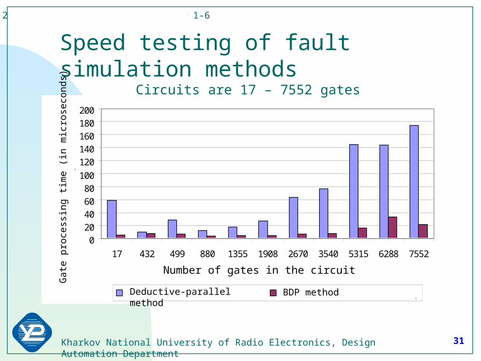
17 432 499 880 1355 1908 2670 3540 5315 6288 7552
Êî ëè÷åñòâî âåí òèëåé
Âð
åìÿ
îá
ðàá
îòê
è î
äí
îãî
â
åíòè
ëÿ
, ìêñ
Äåäóêòèâí î -ï àðàëëåëüí û é ì åòî ä Ì åòî ä î áðàòí î ãî ì î äåëèðî âàí èÿ
Speed testing of fault simulation methodsCircuits are 17 – 7552 gates
Deductive-parallel method BDP method
Number of gates in the circuit
Gat
e pr
oces
sing
tim
e (i
n m
icro
seco
nds)

32Kharkov National University of Radio Electronics, Design Automation Department
DSD 2003, Turkey, Antaliya, September 1-6
0,00
2,00
4,00
6,00
8,00
10,00
12,00
Nem 0,65 0,10 0,33 4,11 5,16 7,81 8,68 5,80 6,24 9,93
МОМ 0,003 0,003 0,003 0,006 0,009 0,017 0,028 0,088 0,208 0,167
ДПМ 0,005 0,014 0,011 0,025 0,053 0,169 0,272 0,772 0,905 1,314
TT 1,00 1,90 2,40 4,50 6,50 7,60 7,80 8,00 8,90 9,10
c432 c499 c880 c1355 c2670 c1908 c3540 c5315 c6288 c7552
Comparison of fault simulation systems speedNemesis, BDP-, DP-method, Turbo-tester. Circuits are 432 – 7552 gates
NemBDPDPTT

33Kharkov National University of Radio Electronics, Design Automation Department
DSD 2003, Turkey, Antaliya, September 1-6
00:00,0
01:26,4
02:52,8
04:19,2
05:45,6
07:12,0
08:38,4
10:04,8
11:31,2
12:57,6
с6288 c10000 c15000 c20000 c25000 c30000 c35000 c40000
Benchmark
Tim
e
Deductive-ParallelBacktraced Quasi ExactBacktraced-Deductive-Parallel
SIGETEST: fault simulation speed testingCircuits are 6288 – 40 000 gates
Topological Deductive parallel

34Kharkov National University of Radio Electronics, Design Automation Department
DSD 2003, Turkey, Antaliya, September 1-6
00:00,0
01:26,4
02:52,8
04:19,2
05:45,6
07:12,0
08:38,4
10:04,8
11:31,2
12:57,6
14:24,0
1 2 3 4 5 6 7 8 9 10
Lx10000
Tim
e,
mm
:ss
Backtraced Quasi ExactBacktraced Deductive ParallelDeductive Parallel
Benchmark, 100 vectors
SIGETEST: fault simulation speed testingCircuits are 1000 – 100 000 gates
Topological Deductive parallel

35Kharkov National University of Radio Electronics, Design Automation Department
DSD 2003, Turkey, Antaliya, September 1-6
SIGETEST – SImulation and GEneration of TEST
Was rewarded with Intel diploma in CAD systems competition, 2003 Universal model of digital systems deductive-parallel analysis Sufficient simulation speed-up due to the back-traced superposition Deductive model of reconvergent fan-out searching Method of topologic fault simulation for tree-like structure Technical solutions for embedded fault simulators The further SIGETEST development: Structural analysis improvement for simulation speed-up Analysis of false fault compensation for flip-flops and latches Theoretical proof of superposition correctness for flip-flop structure Structural analysis for asynchronous circuits Development of compilers from HDL languages Development of hardware accelerators for fault simulation speed-up
36Kharkov National University of Radio Electronics, Design Automation Department
DSD 2003, Turkey, Antaliya, September 1-6
Thank YOU for your attention!