kia sportage 2011-2016 table of contents 99-7344g, 99 ... · especially air bag indicator lights...
TRANSCRIPT

METRA. The World’s best kits.™ metraonline.com © COPYRIGHT 2004-2016 METRA ELECTRONICS CORPORATION
REV.
4/5
/201
6 I
NST9
9-73
44
Installation instructions for part 99-7344
CAUTION! All accessories, switches, climate controls panels, and especially air bag indicator lights must be connected before cycling the ignition. Also, do not remove the factory radio with the key in the on position, or while the vehicle is running.
• ISO DIN radio provision with pocket• Painted Gray or Charcoal to match factory finish G = Gray, CH = Charcoal
• A) Radio trim panel • B) Radio brackets • C) Pocket • D) (4) Panel clips • E) (4) Phillips truss head screws
KIT FEATURES
KIT COMPONENTS
WIRING & ANTENNA CONNECTIONS (sold separately)Wiring Harness: • 70-7304 • HYBL-03 (with NAV) • HYBL-04
Antenna Adapter: • Not required • 40-KI11 (with NAV)
• Panel removal tool • Phillips screwdriverTOOLS REQUIRED
Kia Sportage 2011-201699-7344G, 99-7344CH
Table of Contents
A B C D E
Dash Disassembly ..................................................2
Kit Preparation ........................................................3
Kit Assembly
– ISO DIN radio provision with pocket ...................... 3
99-7344
2
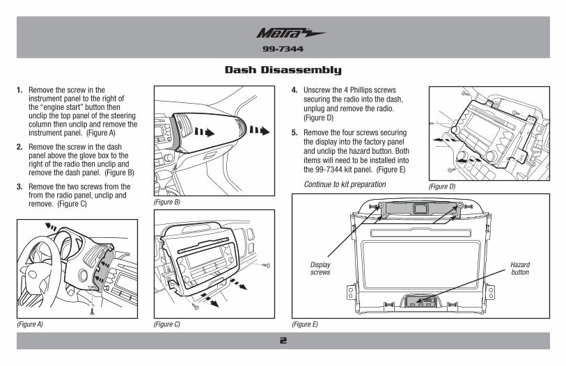
Dash Disassembly
1. Remove the screw in the instrument panel to the right of the “engine start” button then unclip the top panel of the steering column then unclip and remove the instrument panel. (Figure A)
2. Remove the screw in the dash panel above the glove box to the right of the radio then unclip and remove the dash panel. (Figure B)
3. Remove the two screws from the from the radio panel, unclip and remove. (Figure C)
(Figure C)
(Figure B)
(Figure A)
4. Unscrew the 4 Phillips screws securing the radio into the dash, unplug and remove the radio. (Figure D)
5. Remove the four screws securing the display into the factory panel and unclip the hazard button. Both items will need to be installed into the 99-7344 kit panel. (Figure E)
Continue to kit preparation (Figure D)
(Figure E)
Hazardbutton
Displayscrews

99-7344
3
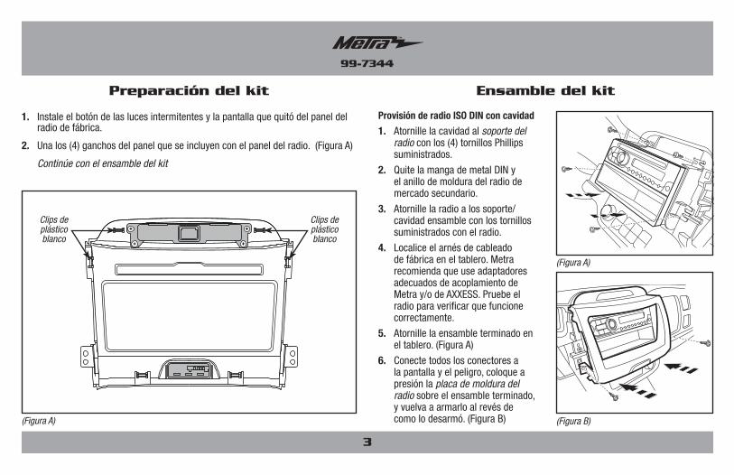
Kit Preparation
(Figure A)
(Figure B)
ISO DIN radio provision with pocket
1. Secure the pocket to the radio brackets using the (4) Phillips screws provided.
2. Remove the metal DIN sleeve and trim ring from the aftermarket radio.
3. Secure the radio to the bracket/pocket assembly using the screws supplied with the radio.
4. Locate the factory wiring harness in the dash. Metra recommends using the proper mating adapter from Metra and/or AXXESS. Test the radio for proper operation.
5. Secure the completed assembly into the dash. (Figure A)
6. Connect all connectors to the display and hazard, snap the radio trim plate over the completed assembly, and then reassemble the dash in reverse order of disassembly. (Figure B)
Kit Assembly
1. Install the hazard button and display previously removed from the factory radio panel.
2. Attach the (4) included panel clips to the radio panel. (Figure A)
Continue to kit assembly
(Figure A)
White plastic clips
White plastic clips

METRA. The World’s best kits.™ metraonline.com © COPYRIGHT 2004-2016 METRA ELECTRONICS CORPORATION
REV.
4/5
/201
6 I
NST9
9-73
44
KNOWLEDGE IS POWEREnhance your installation and fabrication skills by enrolling in the most recognized and respected mobile electronics school in our industry.Log onto www.installerinstitute.com or call 800-354-6782 for more information and take steps toward a better tomorrow.
Metra recommends MECP certified technicians
Installation instructions for part 99-7344
IMPORTANTIf you are having difficulties with the installation of this product, please call our Tech Support line at 1-800-253-TECH. Before doing so, look over the instructions a second time, and make sure the installation was performed exactly as the instructions are stated. Please have the vehicle apart and ready to perform troubleshooting steps before calling.

METRA. The World’s best kits.™ metraonline.com © COPYRIGHT 2004-2016 METRA ELECTRONICS CORPORATION
REV.
4/5
/201
6 I
NST9
9-73
44
Instrucciones de instalación para la pieza 99-7344
¡PRECAUCIÓN! Todos los accesorios, interruptores, paneles de con-troles de clima y especialmente las luces del indicador de las bolsas de aire deben estar conectados antes ciclar la ignición. Además, no quite el radio de fábrica con la llave en la posición o de encendido ni con el vehículo funcionando.
• Provisión de radio ISO DIN con cavidad• Pintada en color gris o gris oscuro para igualar elacabado de fábrica G = gris, CH = gris oscuro
• A) Panel de moldura de radio • B) Soportes del radio • C) Cavidad • D) (4) Ganchos para panel • E) (4) Tornillos Phillips de cabeza segmentada
CARACTERÍSTICAS DEL KIT
COMPONENTES DEL KIT
CABLEADO Y CONEXIONES DE ANTENA (se venden por separado)Arnés de cableado: • 70-7304 • HYBL-03 (con NAV) • HYBL-04
Adaptador de antena: • No se requiere • 40-KI11 (con NAV)
• Herramienta para quitar paneles • Destornillador PhillipsHERRAMIENTAS REQUERIDAS
Kia Sportage 2011-201699-7344G, 99-7344CH
Indice
A B C D E
Desmontaje del tablero ..........................................2
Preparación del kit .................................................3
Ensamble del kit
– Provisión de radio ISO DIN con cavidad ................ 3

99-7344
2
Desmontaje del tablero
1. Quite el tornillo del panel de instrumentos a la derecha del botón de “arranque de motor” y luego desenganche el panel de arriba de la columna de dirección, luego desenganche y quite el panel de instrumentos. (Figura A)
2. Quite el tornillo del panel del tablero arriba de la guantera, a la derecha del radio, y desenganche y quite el panel del tablero. (Figura B)
3. Quite los dos tornillos del panel del radio, desenganche y quite. (Figura C)
(Figura C)
(Figura B)
(Figura A)
4. Desatornille los 4 tornillos Phillips que sostienen el radio en el tablero, desconecte y quite el radio. (Figura D)
5. Quite los cuatro tornillos que sostienen la pantalla en el panel de fábrica y desenganche el botón de las luces intermitentes. Las dos cosas deben instalarse en el panel del kit 99-7344. (Figura E)
Continúe con la preparación del kit (Figura D)
(Figura E)
botón de peligros
tornillos de visualización
99-7344
3
Preparación del kit
(Figura A)
(Figura B)
Provisión de radio ISO DIN con cavidad
1. Atornille la cavidad al soporte del radio con los (4) tornillos Phillips suministrados.
2. Quite la manga de metal DIN y el anillo de moldura del radio de mercado secundario.
3. Atornille la radio a los soporte/cavidad ensamble con los tornillos suministrados con el radio.
4. Localice el arnés de cableado de fábrica en el tablero. Metra recomienda que use adaptadores adecuados de acoplamiento de Metra y/o de AXXESS. Pruebe el radio para verificar que funcione correctamente.
5. Atornille la ensamble terminado en el tablero. (Figura A)
6. Conecte todos los conectores a la pantalla y el peligro, coloque a presión la placa de moldura del radio sobre el ensamble terminado, y vuelva a armarlo al revés de como lo desarmó. (Figura B)
Ensamble del kit
1. Instale el botón de las luces intermitentes y la pantalla que quitó del panel del radio de fábrica.
2. Una los (4) ganchos del panel que se incluyen con el panel del radio. (Figura A)
Continúe con el ensamble del kit
(Figura A)
Clips de plástico blanco
Clips de plástico blanco

METRA. The World’s best kits.™ metraonline.com © COPYRIGHT 2004-2016 METRA ELECTRONICS CORPORATION
REV.
4/5
/201
6 I
NST9
9-73
44
KNOWLEDGE IS POWEREnhance your installation and fabrication skills by enrolling in the most recognized and respected mobile electronics school in our industry.Log onto www.installerinstitute.com or call 800-354-6782 for more information and take steps toward a better tomorrow.
Metra recomienda técnicos con certificación del Programa de Certificación en Electrónica Móvil (Mobile Electronics Certification Program, MECP).
EL CONOCIMIENTO ES PODERMejore sus habilidades de instalación y fabricación inscribiéndose en la escuela de dispositivos electrónicos móviles más reconocida y respetada de nuestra industria. Regístrese en www.installerinstitute.com o llame al 800-354-6782 para obtener más información y avance hacia un futuro mejor.
Instrucciones de instalación para la pieza 99-7344
IMPORTANTESi tiene dificultades con la instalación de este producto, llame a nuestra línea de soporte técnico al 1-800-253-TECH. Antes de hacerlo, revise las instrucciones por segunda vez y asegúrese de que la instalación se haya realizado exactamente como se indica en las instrucciones. Por favor tenga el vehículo desarmado y listo para ejecutar los pasos de resolución de problemas antes de llamar.