kinematic analysis for trajectory generation in one leg of
TRANSCRIPT

Procedia Technology 3 ( 2012 ) 342 – 350
2212-0173 © 2012 Published by Elsevier Ltd.doi:10.1016/j.protcy.2012.03.037
The 2012 Iberoamerican Conference on Electronics Engineering and Computer Science
Kinematic analysis for trajectory generation in one leg of a hexapod robot.
García-López, M.C.a*, Gorrostieta-Hurtado, E.a, Vargas-Soto, E.a,Ramos-Arreguín, J.M.a, Sotomayor-Olmedo,A.a, Moya Morales, J.C.a
aFacultad de Informática-Universidad Autónoma de Querétaro, Facultad de Informática. Av. de las Ciencias s/n Campus Juriquilla Juriquilla, Querétaro, Qro. C.P. 76230 México
Abstract
The legs movement of a walking robot has been widely studied to solve mobility problems on such robots. These studies mainly analyze the movement performed by certain animals like mammals, insects, or reptiles, that later will be mimicked by mechanical systems. In the present work, a kinematic analysis of a single leg of a hexapod robot is introduced and the trajectory generation is implemented. To evaluate the leg movement performance, a simulator was developed in order to analyze the trajectory. © 2012 Published by Elsevier Ltd.
Keywords: Kinematics, walking robot,trajectory.
1. Introduction
Walking robots have been studied in the last three decades in order to reproduce the natural abilities presented in some animals and insects.
Nevertheless, locomotion, in these applications [1] is especially challenging in irregular terrains [2][3]. Legged locomotion allows movement coordination of the mechanism to navigate safely across varied terrain [4]. In such cases it is intended that this type of machines can be independent and autonomous, in other words, do not require human intervention or reduce some restrictions [5].
The animals are naturally adapted to different types of surfaces and with the goal of developing a similar mechanism, scientific communities have been inspired in some natural elements present in animals [6][7][8][9][10][11] trying to imitate to some extent in mechanical design, control, navigation and so on [12].
* Corresponding author. Tel.: 192 12 00 ext. 5941. E-mail address: [email protected].
Available online at www.sciencedirect.com

343 García-López, M.C. et al. / Procedia Technology 3 ( 2012 ) 342 – 350
These investigations have generated interest about the use of legs or wheels for robot movement. The principal difference between them is that the use of legs is better for motion and adaptation to irregular terrains than wheels which have a limited movement in this type of environments [13][14]. Therefore, understanding of the behaviour of animal locomotion is of main concern for the research community.
One of the main challenges in the development of robots is the locomotion system design, which involves the interaction of structures composed of prismatic or rotational joints which emulates the motion functions existing in nature, allowing adapting to uneven terrain [15]. It also needs to deal with problems like the mechanical complexity existing in legs, the mechanism stability, power consumption, synchronization of the links in each of the robots joints and the control of number of degrees of freedom that is requiring. In case of a quadruped robot with three degrees of freedom per leg it is required to synchronize twelve degrees of freedom and for a hexapod robot eighteen angles in total.
The legs location regarding the displacement surface is important in the robot’s stability, the same way as the observation of the center of gravity, owing to that if these do not have a proper synchronization and do not provide the necessary support to the system base, it will lose balance and will fall or its movements will be inefficient causing perhaps a greater energy consumption [16]. This synchronization will depend of the mobility control of the legs for its displacement, because if the robot moves within the established limits, collisions between the links will be avoided and therefore the system will not be affected [17]. The length and design of the legs is essential in robot locomotion, because the trajectory that is implemented in each of the articulation depend on them.
If we have the trajectory that allows a smooth movement, we will not see the robot stability affected by a hard movement and we can determine the progress of the movement in a given time. Also, if the robot moves within the established limits, the collision risk is avoided and the system will be safe.
The old tradition to solve the problems mentioned above and to test the hypotheses, a prototype has been developed, with the disadvantage of loss of time and resources. The currently progress in programming and graphical environments, allows the development of tools such as simulators, which provide a validation of the physical system for trajectory selection to get a successful behavior, as well as the control algorithms developed [18][19][20].
2. Leg configuration in walking robots.
Because a robot can have two, four, six or eight extremities, the classification of walking robots is carried out regarding its legs number [21]. Another classification takes into account the arrangement or disposal or fixation points respect to the body, as well as the orientation to the base.
The leg configuration is inspired primarily on animal gait, such as reptiles, which have legs and bodies planned to move over swamps and muddy terrains [22]. In contrast, mammals have the body above the legs, less support in the base, lower power consumption to support the body but need best stability than other types of animals [23].
The orientation of the legs respect to the body of the walking robot can be done with one of the three configurations: frontal, sagittal and circular (Fig. 1), the first two are characteristic of some animals. In the frontal configuration the directions are perpendicular to the advancement of the legs position, unlike the sagittal, which moves parallel to the robot legs, while in the circular arrangement, where the legs are positioned radially to the body of the system allowing the mechanism to move in any direction [24].
Fig. 1. (a) Front disposal; (b) Sagittal disposal; (c) Circular disposal.
In each of one the above classifications different types of joins points with respect the body of the mechanism can be present: some of these configurations are the mammalian, reptilian and arachnid type.
In the mammalian configuration (Fig. 2) the legs below the body and can position the knees in different positions, depending on the application it requires.

344 García-López, M.C. et al. / Procedia Technology 3 ( 2012 ) 342 – 350
Fig. 2. (a) Knees outwards; (b) Knees with the same orientation; (c) Knees inwards.
The principal characteristic of the Reptilian type (Fig. 3(a)) is that the legs are placed on both ends of the protruding body and knees to the side of the base. On the other hand in the spider-like configuration (Fig. 3 (b)), is characterized in which their extremities are situated on both sides, sticking the knees at the top of the spider’s body [10].
Fig. 3. (a) Reptile configuration; (b) Spider configuration.
3. Leg characteristics.
The legs characteristics depend on of the factors related to the application in which the robot is required, the terrain form, the legs work space, the required energy for the movement, the weight that can support, are to be valued in order to define the physical design and end of these extremities.
In order to obtain maximum leg work space with a minimal structure, there are two types of geometrical arrangements that are used for its design [25]. In this case, we consider three degrees of freedom, one for each foot and two types of geometry.
The configuration of type one (Fig. 4 (a)) is characterized by its first axis which is parallel to the vertical axis of the robot’s body, while the second and third axis are parallel to the transverse plane of the base. This configuration has been used in investigations such as the robot "LittleDog" [26].
In the type two configuration (Fig. 4 (b)) the second and third axes are parallel with each other and perpendicular to the first axis of this configuration, an example is the robot Silo4 [27].
Fig. 4. (a) Geometric arrangement type one; (b) Geometric arrangement type two.
In order to have a minimal structure leverage, the work space and the momentum for the body movement is performed by one leg, while the movements of other joints are shorts [28][29]. The used design is based on the geometric arrangement of type two (Fig. 5), which has three degrees of freedom. The first angle θ1 is rotated 180° about its axis, perpendicular to the axes of θ2 and θ3; the latter are rotated 90° and 180° respectively with their axes parallel to each other.

345 García-López, M.C. et al. / Procedia Technology 3 ( 2012 ) 342 – 350
Fig. 5. (a) Leg disposition; (b) Leg build in OpenGL.
Having established the leg geometrical parameters, the coordination of its three degrees of freedom (Fig. 5 (b)) is crucial to generate locomotion. In such cases, it is needed to describe in mathematical form the relationship between the join variables, position and orientation of the leg [30]. To determinate the kinematic in this case is a good solution because considering the movement without regard of the functions that produce them, also involves the relationship between the joint variable space and the workspace where the robot will move the leg of the hexapod robot.
In the particular case of the foot shown in Fig. 5(b), it will be described by defining four magnitudes that are associated with each joint. One of the magnitudes is the joint variable and the remaining three parameters are fixed. These parameters will define a Denavit-Hartenberg representation, which involves the link between rotation and translation of the adjacent links [25]. This representation implies a composite transformation by four elementary transformations, with which the general form for each joint will be obtained (1).
1000
coscossincossinsin
sinsincoscoscossin
0sincos
1111
1111
1
1
iiiiiii
iiiiiii
iii
ii
d
d
a
T
(1)
Determining the transformation parameters of each link will serve to determine the composite transformation which relates the link variables q1, q2 and q3. With these calculations, the position and Cartesian orientation (p) of the last joint (2) can be estimated. The part that makes the contact with the floor is the last joint, where φ is a non lineal set of functions [30].
TTTTqp nn
n011
201 ....)( (2)
Based on it, the kinematics of the leg of a hexapod robot was determined, which has three rotational joints (Fig. 7(a)). Table 1
shows the Denavit-Hartenberg (D-H) parameters that describe the joins leg: length, (ɑi-1), degree of rotation (αi-1), in case of the prismatic joins this variable is the displacement (ɑi), the angle (θi) of each of this links of the robot.
Table 1. D-H parameters of the hexapod robot leg.
i 1ia 1i id i
1 L1 0° 0 1
2 L2 180° 0 2
3 L3 90° 0 3
The transformation matrices of the three links can be described as:
346 García-López, M.C. et al. / Procedia Technology 3 ( 2012 ) 342 – 350
1000
0100
00cossin
00sincos
11
11
10T
(3)
1000
0100
00cossin
0sincos
22
122
21
L
T
(4)
1000
0100
00cossin
0sincos
33
233
32
L
T
(5)
The result obtained from the transformation matrix is presented on equation (6), and it is used to determine the position from
the link that touches the ground to the robot’s body.
1000
0100
)sinsin()sin(0coscoscos)sinsinsin
)coscos()cos(0sinsinsincoscoscos
31211321321
31211321321
30 LL
LL
T
(6)
The equation (6) is the direct kinematics of the robot, and it is used to determine the position and orientation of the fixing
point of the leg.
4. Path generation of the leg.
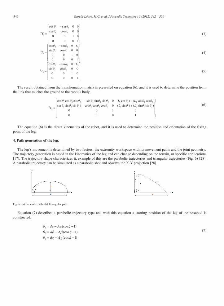
The leg´s movement is determined by two factors: the extremity workspace with its movement paths and the joint geometry. The trajectory generation is based in the kinematics of the leg and can change depending on the terrain, or specific applications [17]. The trajectory shape characterizes it, example of this are the parabolic trajectories and triangular trajectories (Fig. 6) [28]. A parabolic trajectory can be simulated as a parabolic shot and observe the X-Y projection [28].
Fig. 6. (a) Parabolic path; (b) Triangular path.
Equation (7) describes a parabolic trajectory type and with this equation a starting position of the leg of the hexapod is constructed.
)1(cos
)1(cos
)1(cos
3
2
1
Ad
Ad
Ad
(7)

347 García-López, M.C. et al. / Procedia Technology 3 ( 2012 ) 342 – 350
Where dγ, dβ, dχ is giving by the angles θ1, θ2, θ3 respectively, the variable Aγ defines the length of the step that has the leg of hexapod robot and the variables Aβ, Aχ, defines the height of the step. The fixing point presents a function in the time; therefore another factor that is required is the mobility angle (ξ) for the robot [17].
The behavior of this triangular trajectory is described by the equation (8), where the constant k1 is the variable of slope at the end of step [17].
13
12
1
)1(cos
)1(cos
)1(cos
k
k
eAd
eAd
Ad
(8)
5. Simulator.
The tools obtained in the research fields such as programming and simulation provide a solid framework to validate and corroborate physic systems, the stability degree in some mechanisms and reducing the construction of prototypes [31]. Based on it, this work develops a model and simulation of a robotic leg. Fig. 7 illustrates the process and technologies implemented in a leg model and simulation.
Fig. 7. Block diagram of the simulator design
Geometric configuration: A key feature in robot simulations is determining the accurate selection of link or joint to walk. The configuration used in this robot is shown in Fig. 5(b). Then a mechanic design implemented in CAD tools will be done.
CAD Design: The 3D design software provides a straightforward and semiautomatic way to generate and ensemble mechanic elements. It shall determine the movement range of each piece; moreover a complete preview of the full model would be shown. Finally this tool can export the generated model to a wide range of platforms, in this work the authors choose the extension .wrl to be integrated with OpenGL.
VRML 2.0: The VRML 2.0 of each mechanic piece contains a set of points that holds its geometric definition. The VRML cannot be directly integrated in OpenGL, the VRML files must be processed by a C++ interpreter which transforms the code into header C++ files or .h extension files, later on, the integration with OpenGL can be performed.
Open GL: The program, made in OpenGL, use the header files of each mechanic piece, for further works a hexapod robot will be developed by instancing the pre-existed leg models. The developed application provides a user interaction interface by using a keyboard which allows manipulating each angle independently.
The Fig. 7 shows the results of the kinematics and trajectory calculus solved in Matlab. Then, these results will be exported and integrated into an OpenGL simulation.
6. Results.
Considering the equations previously presented, and considering ξ from 0 to π, the values of the variables that let us calculate the trajectory and behavior of a single leg from a hexapod robot are described (9).
10
15
10
A
A
A
310
4
345
d
d
d
(9)
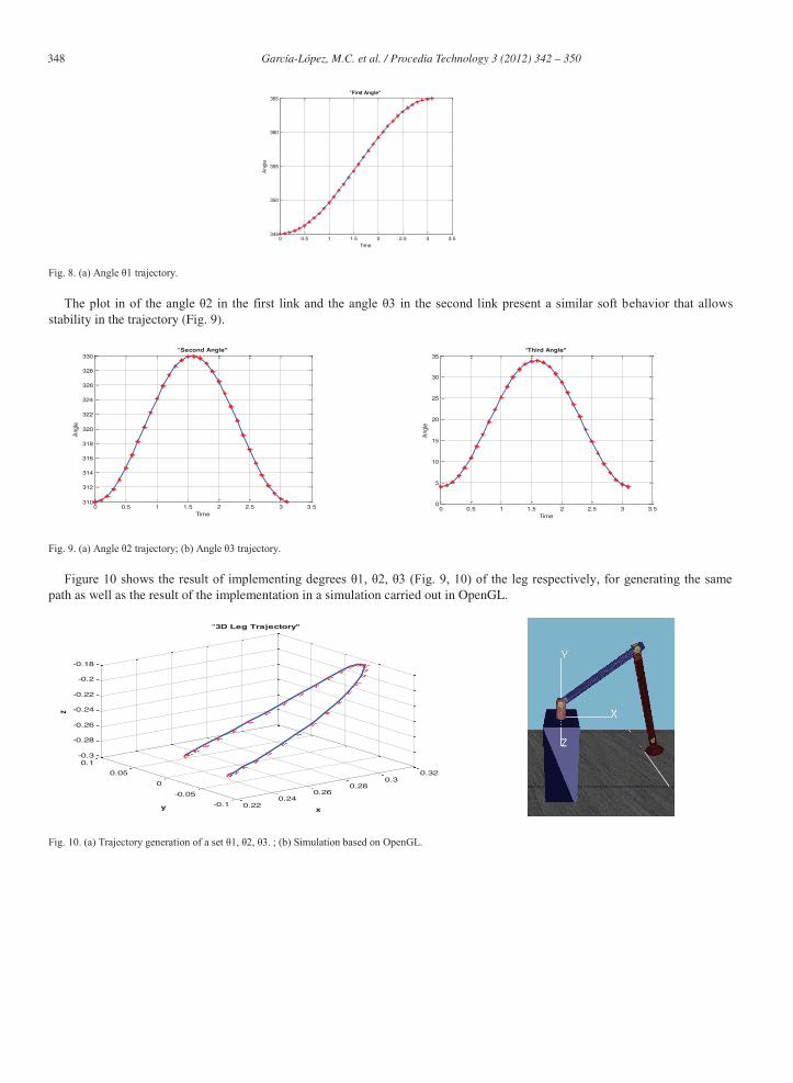
In Fig. 8, the trajectory of the angle θ1 is shown, which corresponds to the first link. It can be appreciated that the movement
that reaches is soft and without variations that affect the equilibrium of the robot.
348 García-López, M.C. et al. / Procedia Technology 3 ( 2012 ) 342 – 350
0 0.5 1 1.5 2 2.5 3 3.5
345
350
355
360
365"First Angle"
Time
Angle
Fig. 8. (a) Angle θ1 trajectory.
The plot in of the angle θ2 in the first link and the angle θ3 in the second link present a similar soft behavior that allows stability in the trajectory (Fig. 9).
0 0.5 1 1.5 2 2.5 3 3.5
310
312
314
316
318
320
322
324
326
328
330"Second Angle"
Time
Angle
0 0.5 1 1.5 2 2.5 3 3.50
5
10
15
20
25
30
35"Third Angle"
Time
Angle
Fig. 9. (a) Angle θ2 trajectory; (b) Angle θ3 trajectory.
Figure 10 shows the result of implementing degrees θ1, θ2, θ3 (Fig. 9, 10) of the leg respectively, for generating the same path as well as the result of the implementation in a simulation carried out in OpenGL.
0.220.24
0.260.28
0.30.32
-0.1
-0.05
0
0.05
0.1-0.3
-0.28
-0.26
-0.24
-0.22
-0.2
-0.18
x
"3D Leg Trajectory"
y
z
Fig. 10. (a) Trajectory generation of a set θ1, θ2, θ3. ; (b) Simulation based on OpenGL.

349 García-López, M.C. et al. / Procedia Technology 3 ( 2012 ) 342 – 350
7. Conclusions and future work.
The trajectory generation is a fundamental step in the kinematic and dynamic study of a hexapod robot, as well as the development of the fix or free locomotion of the robot. Here, if there is an inadequate relationship of the angles θ1, θ2 and θ3, and considering the geometric arrangement of the legs, we could not achieve the correct system’s movement, and consequently the robot stability could be affected, due to the fact that it doesn’t exist a relationship in the angles of the leg, because if every angle have values which are not proper and performing the tripod movement, then the robot could fall down.
The leg simulation was developed in C++ with OpenGL libraries, and it is an approach of the trajectory movement of the robot´s leg in a real mechanism. As a future work, a simulator of the whole hexapod robot will be developed, including some algorithms that allow analyzing different stability parameters, locomotion, trajectory planning and some artificial intelligence algorithms like neural networks for the development of movements similar to the animals.
Acknowledgements
We would like to thank Consejo y Ciencia de Tecnología del Estado de Querétaro (CONCYTEQ) by the 2012-01 science and technology activities programs, and the Universidad Autónoma de Querétaro (UAQ) for the facilities and support.
References
[1] Mustafa Suphi Erden, “Optimal Protraction of a Biologically Inspired Robot Leg”, 20011, J Intell Robot Syst, 64:301-322, DOI 10.1007/s10846-011-
9538-8.
[2] Manuel F. Silva, J. A. Tenreiro Machado, July-2006, “A Historical Perspective of Legged Robots”, Journal of Vibration and Control 2007 13: 1447, DOI: 10.1177/1077546307078276.
[3] Joaquin Estremera and Pablo Gonzales de Santos, “Generating Continuous Free Crab Gaits for Quadruped Robots on Irregular Terrain”, 2005, IEEE Transactions on Robotics, Vol. 21, No. 6. December.
[4] E. Calle, I. Ávila, J. Zambrano, Octubre-2007, “Diseño e Implementación de un Robot Móvil Cuadrúpedo”, Revista Tecnológica ESPOL, Vol. 20, N. 1, ISSN : 0257-1749. pp. 65-72.
[5] Zu Guang Zhang, Hiroshi Kimura and Kunikatsu Takase, “Adaptive Running of a Quadruped Robot Using Forced Vibration and Synchronization”, in Proceeding of the Journal of Vibration and Control/SAGE, May 4, 2006, pp.1361–1383.
[6] Kristi A. Morgansen, Benjamin I. Triplett, and Daniel J. Klein, (2007), “Geometric Methods for modeling a Control of Free-Swimming Fin-Actuated
Underwater Vehicles”, SUBMITTED TO THE IEEE TRANSACTIONS ON ROBOTICS, December. [7] Paolo Arena, Holk Cruse, Mattia Frasca, “2001”, “Cellular Nonlinear Network-Based Bio-Inspired Decentralized Control of Locomotion for Hexapod
Robots”, Adaptive Behavior 2002 10: 97, DOI: 10.1177/1059712302010002002. [8] Uluc Saranli, Martin Buehler and Daniel E. Koditschek, 2000, “RHex: A Simple and Highly Mobile Hexapod Robot”, The International Journal of
Robotics Research 2001 20: 616, DOI: 10.1177/02783640122067570, July.
[9] Jorge Cortes, Sonia Martinez James, P. Ostrowski, Kenneth A. McIsaac, 2001,” Optimal Gaits for Dynamic Robotic Locomotion”, September.
[10] Vargas Soto Jose Emilio, “Diseño un Robot Hexápodo Tipo Hormiga”, 2006, 8vo. Congreso Mexicano de Robótica, COMRob 2006. [11] Paolo Arena, Luigi Fortuna, Mattia Frasca, and Giovanni Sicurella, 2004, “An Adaptive, Self-Organizing Dynamical System for Hierarchical Control
of Bio-Inspired Locomotion”, IEEE TRANSACTIONS ON SYSTEMS, MAN, AND CYBERNETICS—PART B: CYBERNETICS, VOL. 34, NO. 4,
AUGUST.
[12] Hiroshi Kimura, Yasuhiro Fukuoka, Avis H. Cohen, 2007,”Adaptive Dynamic Walking of a Quadruped Robot on Natural Ground Based on Biological
Concepts”, The International Journal of Robotics Research 2007 26: 475, DOI: 10.1177/0278364907078089.
[13] Stanley Kwok-Kei Chu and Grantham Kwok-Hung Pang, 2002, “Comparison Between Different Model of Hexapod Robot in Fault-Tolerant Gait”, IEEE TRANSACTIONS ON SYSTEMS, MAN, AND CYBERNETICS—PART A: SYSTEMS AND HUMANS, VOL. 32, NO. 6, NOVEMBER.
[14] Zhiying Wang, Xilun Ding, Alberto Rovetta, Alessandro Giusti, 2001, “Mobility analysis of the typical gait of a radial symmetrical six- legged robot”, Contents list available at Science Direct, 31, May.
[15] J. P. Flores Fernandes, J. C. Pimenta Claro, Fernando Ribeiro. Design of a Hexapod Robotic System.
[16] Jing Liu, Min Tan and Xiaoguang Zhao, 2007, “Legged robots – an overview”, Transactions of the Institute of Measurement and Control 2007 29: 185, DOI: 10.1177/0142331207075610.
350 García-López, M.C. et al. / Procedia Technology 3 ( 2012 ) 342 – 350
[17] Efrén Gorrostieta-Hurtado, Emilio Vargas-Soto. Diseño de un Controlador Aplicado a la Generación de Pasos en un Robot Caminante.
[18] Kris Hauser, Timothy Bretl, Jean-Claude Latombe, Kensuke Harada and Brian Wilcox, 2008, “Motion Planning for Legged Robots on Varied Terrain”, The International Journal of Robotics Research 2008 27: 1325, DOI: 10.1177/0278364908098447.
[19] Kris Hauser, Jean-Claude Latombe, 2009, “Multi-modal Motion Planning in Non-expansive Spaces”, The International Journal of Robotics Research OnlineFirst, published on October 22, 2009 as doi: 10.1177/0278364909352098.
[20] Efrén Gorrostieta y Emilio Vargas Soto, 2007, “Algoritmo Difuso de la Locomoción Libre para un Robot Caminante de Seis Patas”, Computación y Sistemas, Vol. 11 No. 3, 2008, pp. 260-287 ISSN 1405-5546.
[21] Philip Holmes, Robert J. Full, Dan Koditschek, John Guckenheimer. The Dynamics of Legged Locomotion: Models, Analyses, and Challenges.
Society for Industrial and Applied Mathematics, Vol.48, No.2, 2006, pp.207–304.
[22] Manuel f. Silva, j. A. Tenreiro machado. Fractional Order PD_ Joint Control of Legged Robots, 2006, Journal of Vibration and Control. DOI:
10.1177/1077546306070608.
[23] Raibert M. Running on Four Legs As Though The Were One, 1986, IEEE Journal of Robotics and Automation, Vol. RA2, No. 2.
[24] Md. Masum Billah, Mohiuddin Ahmed, and Soheli Farhana, 2008, “Walking Hexapod Robot in Disaster Recovery Developing Algorithm for Terrain
Negotiation and Navigation”, World Academy of Science, Engineering and Technology. [25] Mustafa Suphi Erden and Kemal Leblebicioglu. Torque Distribution in a Six-Legged Robot, 2007, IEEE TRANSACTIONS ON ROBOTICS, VOL.
23, NO. 1.
[26] J. Zico Kolter, Mike P. Rodgers, and Andrew Y. Ng, “A Control Architecture for Quadruped Locomotion Over Rough Terrain”, Computer Science Department, Stanford University, Stanford, CA 94305.
[27] Pablo Gonzalez de Santos, José a. Gálvez, Joaquin Estremera, and Elena García, 2003, “A True Walking Robot for the Comparative Study of Walking Machine Techniques”, I IEEE Robotics & Automation Magazine, December.
[28] Efrén Gorrostieta y Emilio Vargas Soto. Algoritmo Difuso de Locomoción Libre para un Robot Caminante de Seis Patas, 2007.
[29] G. Figliolini, S.-D. Stan, P. Rea. Motion Analysis of the Leg Tip of a Six-Legged Walking Robot, 2007, 12th IFToMM World Congress, Besançon
(France).
[30] Aníbal Ollero Baturote. Robótica Manipuladores y Robots Móviles, 2001, Edit. Alfaomega. ISBN 9701507584.
[31] J. A. Soto Cajiga, J. E. Vargas Soto, J. C. Pedraza Ortega, 2006, Generación de trayectorias para un robot manipulador utilizando procesamiento de
imágenes y splines. Segundo Congreso Internacional de Ingeniería, UAQ, Marzo.