kinematic analysis of single-stage … · in this paper was performed kinematic analysis of actual...
TRANSCRIPT

machine design, Vol.7(2015) No.4, ISSN 1821-1259 pp. 113-118
*Correspondence Author’s Address: University of Kragujevac, Faculty of Engineering, Sestre Janjic 6, 34000 Kragujevac, Serbia, [email protected]
Preliminary note
KINEMATIC ANALYSIS OF SINGLE-STAGE CYCLOIDAL SPEED REDUCER Ivan PANTIĆ1 - Mirko BLAGOJEVIĆ1,*
1 Faculty of Engineering, University of Kragujevac, Kragujevac, Serbia Received (22.11.2015); Revised (18.12.2015); Accepted (21.12.2015) Abstract: Rapid development of new technologies cause appearance of different softwares, which make the machine elements and systems development process faster and easier. In addition, newly developed modules of these softwares enable modeling of working processes of mechanical systems under conditions that are very similar to actual real conditions. In this paper was performed kinematic analysis of actual newly designed single-stage cycloidal speed reducer using the softwares Autodesk Inventor and Solidworks (analysis of angular velocity and circumferential velocity of vital elements of cycloidal speed reducer, as well as trajectories of characteristic points of these elements). Then was performed mutual comparison of obtained results as well as comparison of these results to theoretical values. Based on performed analysis, it can be concluded that results are very similar to theoretical values. Therefore, simulations can be very helpful in new complex mechanical systems development process.
Key words: cycloidal speed reducer, kinematic analysis, circumferential velocity, angular velocity, simulation 1. INTRODUCTION Product development process involves several phases in which are performed constant improvements of the quality so it could brake through on global market. On today’s market, besides quality, shortening the development period is of great importance. Since computer technology is on very high level development period can be significantly shorten. Thanks to the use of modern softwares, it is possible to perform very complex analysis of new product in its development period without prototyping. The results obtained from these analyzes are very accurate and relevant in further product development process. In this paper, both Autodesk Inventor i Solidworks softwares were used because of their dynamic simulation modules. The research subject in this paper is single-stage cycloidal speed reducer. 2. CYCLOIDAL SPEED REDUCERS Cycloidal speed reducers belong to the group of planetary gears. Compared to ordinary involute tooth geared reducers, they differ by type of gearing. In there reducers are used gears with cycloidal gearing – cycloid discs. From the kinematic and dynamical aspect, cycloid discs have numerous advantages compared to involute gears. Concave and convex surface are in mutual contact during meshing process, which reduces the contact pressure and wear of tooth flanks. Cycloidal speed reducers are widely used in modern industry. The most common areas of their application are, [1]: robot industry, satellites, tool machines, bridge cranes, transporters. Cycloidal speed reducers (Fig. 1) are very widely used thanks to numerous characteristics such as long and reliable operating life, very wide range of possible transmission ratios, high efficiency, extremely reliable work in dynamic load conditions, it is a very compact device.
Fig.1. Single-stage cycloidal speed reducer
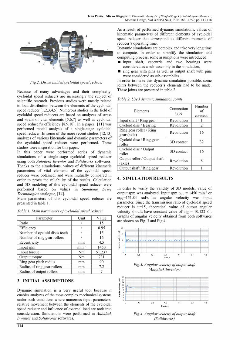
Cycloidal speed reducer working principle is as follows, (Fig. 2): On the input shaft (1) is eccentric (2) with bearings (3), on which cycloid discs (4) are mounted. When input shaft rotates complex movement of cycloid discs occurs. The two main factors that influence this movement are the influence of eccentric and the influence of contact between cycloid discs and ring gear rollers (5) which are mounted in ring gear, on pins (6). Cycloid discs are also in contact with output rollers (8) which are mounted on output shaft (8), on pins (9), so they transmit rotational movement to output shaft. It is known that if the number of cycloid disc teeth is n then number of ring gear rollers is equal n+1. As a result of their contact with ring gear rollers, cycloid disc rotate in opposite direction compared to input shaft. This movement is transmitted to output shaft.
Ivan Pantic, Mirko Blagojevic: Kinematic Analysis of Single-Stage Cycloidal Speed Reducer; Machine Design, Vol.7(2015) No.4, ISSN 1821-1259; pp. 113-118
114
Fig.2. Disassembled cycloidal speed reducer
Because of many advantages and their complexity, cycloidal speed reducers are increasingly the subject of scientific research. Previous studies were mostly related to load distribution between the elements of the cycloidal speed reducer [1,2,3,4,5]. Numerous studies in the field of cycloidal speed reducers are based on analyzes of stress and strain of vital elements [5,6,7] as well as cycloidal speed reducer’s efficiency [8,9,10]. In a paper [11] was performed modal analysis of a single-stage cycloidal speed reducer. In some of the more recent studies [12,13] analyzes of various kinematic and dynamic parameters of the cycloidal speed reducer were performed. These studies were inspiration for this paper. In this paper were performed series of dynamic simulations of a single-stage cycloidal speed reducer using both Autodesk Inventor and Solidworks softwares. Thanks to the simulations, values of different kinematic parameters of vital elements of the cycloidal speed reducer were obtained, and were mutually compared in order to prove the reliability of the results. Calculation and 3D modeling of this cycloidal speed reducer were performed based on values in Sumitomo Drive Technologies catalogue, [14]. Main parameters of this cycloidal speed reducer are presented in table 1.
Table 1. Main parameters of cycloidal speed reducer
Parameter Unit Value Ratio / 15 Efficiency / 0.95 Number of cycloid discs teeth / 15 Number of ring gear rollers / 16 Eccentricity mm 4.5 Input rpm min-1 1450 Input torque Nm 51.237 Output torque Nm 731 Ring gear pitch radius mm 90 Radius of ring gear rollers mm 7.2 Radius of output rollers mm 7
3. INITIAL ASSUMPTIONS Dynamic simulation is a very useful tool because it enables analyzes of the most complex mechanical systems under such conditions where numerous input parameters, relative movement between the elements of the cycloidal speed reducer and influence of external load are took into consideration. Simulations were performed in Autodesk Inventor and Solidworks softwares.
As a result of performed dynamic simulations, values of kinematic parameters of different elements of cycloidal speed reducer that correspond to different moments of reducer’s operating time. Dynamic simulations are complex and take very long time to compute. In order to simplify the simulation and computing process, some assumptions were introduced: input shaft, eccentric and two bearings were
considered as a sub-assembly in the simulation, ring gear with pins as well as output shaft with pins
were considered as sub-assemblies. In order to make this dynamic simulation possible, some joints between the reducer’s elements had to be made. These joints are presented in table 2.
Table 2. Used dynamic simulation joints
Elements Connection
type
Number of
connect. Input shaft / Ring gear Revolution 1 Cycloid disc / Bearing Revolution 2 Ring gear roller / Ring gear (axle)
Revolution 16
Cycloid disc / Ring gear roller
3D contact 32
Cycloid disc / Output roller
3D contact 16
Output roller / Output shaft (axle)
Revolution 8
Output shaft / Ring gear Revolution 1 4. SIMULATION RESULTS In order to verify the validity of 3D models, value of output rpm was analyzed. Input rpm nUL = 1450 min-1 or ωUL=151.84 rad/s as angular velocity was input parameter. Since the transmission ratio of cycloidal speed reducer is u=15, theoretical value of output angular velocity should have constant value of ωIZ = 10.122 s-1. Graphs of angular velocity obtained from both softwares are shown on Fig. 3 and Fig.4.
Fig.3. Angular velocity of output shaft (Autodesk Inventor)
Fig.4. Angular velocity of output shaft (Solidworks)

Ivan Pantic, Mirko Blagojevic: Kinematic Analysis of Single-Stage Cycloidal Speed Reducer; Machine Design, Vol.7(2015) No.4, ISSN 1821-1259; pp. 113-118
115
Difference in forms of graphs of angular velocities can be noticed from Fig.3 and Fig.4. In Autodesk Inventor software value of angular velocity oscillates around its mean value, while in Solidworks there are no such oscillations, but is obtained approximately constant value. Comparative graph of angular velocity of output shaft of both results from Autodesk Inventor, Solidworks and theoretical value is shown on Fig.5.
Fig.5. Comparison of angular velocities
The graph shows that obtained values of output shaft’s angular velocity deviate slightly from theoretical value, which means 3D model of cycloidal speed reducer as adequate for further analyzes.
β = 0
β = 120°
β = 240°
β=360°
Fig.6. Cycloid disc – ring gear rollers meshing process
Thanks to the performed dynamic simulations, values of certain kinematic parameters, which describe the
movement of elements of the cycloidal speed reducer, were obtained. The most attention was naturally dedicated to cycloid disc, since it’s the most important element of the cycloidal speed reducer. Cycloidal disc’s movement is very complex. It consists of rotation which results from eccentric’s rotation in same direction as input shaft and its rotation in opposite direction which results from meshing with central gear rollers. Meshing principle between cycloid disc and central gear rollers is shown in Fig.6. Initial moment involves direct contact between one of ring gear rollers and point that correspond to tooth root of the cycloid disc. One full rotation of the input shaft (β=360°) will cause such movement of cycloid disc that at that point characteristic ring gear roller will be in contact with point that corresponds to the root of the nest cycloid disc’s tooth. Mutual position of one characteristic ring gear roller and cycloid disc at moments that correspond to input shaft’s rotation angles of β=0°, β=120°, β=240° i β=360° is shown on Fig.6. For the purposes of this paper, characteristic point Q of cycloid disc which kinematic parameters will be analyzed (Fig. 7).
Fig.7. Cycloid disc’s characteristic point Q
Trajectory of the point Q at point where input shaft rotates twice (β=720°) is shown in Fig. 8.
Fig.8. Trajectory of the point Q
It can be noticed that point Q has very complex trajectory. A specific detail of trajectory occurs as a result of meshing between cycloid disc and central gear rollers. This detail is shown in Fig. 9.

Ivan Pantic, Mirko Blagojevic: Kinematic Analysis of Single-Stage Cycloidal Speed Reducer; Machine Design, Vol.7(2015) No.4, ISSN 1821-1259; pp. 113-118
116
Fig.9. Characteristic detal of trajectory
Value of distance between point Q and central axis of the cycloidal speed reducer is shown in Fig. 10. Maximum value is calculated as a sum of value from Fig. 7 and eccentricity, and minimum value is calculated when value eccentricity is subtracted from value in Fig. 7.
Fig.10. Position of point Q
Velocity of the point Q (Fig.11 Autodesk Inventor; Fig.12 Solidworks) doesn’t have constant value, but changes depending on the position of cycloid disc in relation to central gear rollers.
Fig.11. Velocity of the point Q (Autodesk Inventor)
Fig.12. Velocity of the point Q (Solidworks)
Comparative graph of velocities obtained in both softwares is shown in Fig. 13.
Fig.13. Comparative graph of velocitirs of the point Q
Comparison between values of velocity of point Q is shown in table 3 ( Autodesk Inventor and Solidworks).
Table 3. Deviation of velocity of the point Q
Autodesk Inventor
Solidworks Deviation
% Maximum
velocity, mm/s 1199.12 1203.463 0.362
Average velocity, mm/s
781.063 863.753 10.586
Besides analysis of cycloid disc, kinematic analysis of output mechanism (output mechanism - output rollers and output shaft together) was performed. Output shaft is connected to output rollers. As a result of these rollers contact with cycloid there is rotational movement of output shaft. Output rollers roll in openings of cycloid disc (Fig. 14).
Fig.14. Kinematics of output mechanism
Output rollers move along a circular path due to their connection with output shaft. However, due to their rolling in corresponding openings in cycloid discs, characteristic point of output roller moves along a complex trajectory. Point P was chosen as a characteristic point of output roller since it’s the point that describes rolling of the output roller the best way. Trajectory of the point P is shown in Fig. 15.
Fig.15. Trajectory of the point P

Ivan Pantic, Mirko Blagojevic: Kinematic Analysis of Single-Stage Cycloidal Speed Reducer; Machine Design, Vol.7(2015) No.4, ISSN 1821-1259; pp. 113-118
117
Output roller rotates around its axis, but also around central axis of the cycloidal speed reducer due to its connection with output shaft. Graph of its angular velocity around its own axis is shown in Fig. 16.
Fig.16. Angular velocity of the output roller
Comparative angular velocity graph of three, random chosen, output rollers is shown in Fig. 17. This graph shows that all output rollers rotate with almost identical values of angular velocities.
Fig.17. Comparison between angular velocities of three
output rollers This comparison will be expanded by comparison of circumferential velocities. Diagram of circumferential velocity of one output roller i.e. velocity of characteristic point P is shown in Fig. 18. Value of velocity of the point P is not constant but oscillates around its mean value.
Fig.18. Circumferential velocity of output roller
(Autodesk Inventor)
Given the fact that dynamic simulation was performed in two softwares, diagram of circumferential velocity obtained from Solidworks should be considered. Diagram of circumferential velocity of one output roller is shown in Fig. 19. This roller is not randomly chosen, because it is the same roller as in analysis in Autodesk Inventor.
Fig.19. Circumferential velocity of output roller
(Solidworks) As a result of comparison between the results from both softwares, the comparative diagram is obtained. This comparative diagram is shown in Fig. 20.
Fig.20. Comparative diagram of circumferential
velocities of output rollers Since there are eight output rollers in this cycloidal speed reducer, maximum and average values of circumferential velocities of every roller are determined, and shown in table 4. Table 4. Values of circumferential velocities of output rollers
Out
put
roll
er Maximum velocity,
mm/s Average velocity,
mm/s Autodesk Inventor
Solidworks Autodesk Inventor
Solidworks
1 1359.95 1308.52 875.29 802.8 2 1354.12 1318.88 880.33 799.66 3 1346.45 1323.18 881.55 725.69 4 1346.74 1329.97 877.41 751.69 5 1351.95 1319.93 874.57 801.41 6 1346.4 1322.55 881.36 749.13 7 1340.54 1322.04 881.89 715.72 8 1345.52 1317.44 879.06 769.18
4. CONCLUSION By performing the dynamic simulations of a designed single-stage cycloidal speed reducer, numerous values of kinematic parameters were obtained, which was the primary goal of this study. Obtained results lead to following conclusions: Values of certain kinematic parameters slightly
deviate from theoretical values which means these results are relevant and can be used in product development process.

Ivan Pantic, Mirko Blagojevic: Kinematic Analysis of Single-Stage Cycloidal Speed Reducer; Machine Design, Vol.7(2015) No.4, ISSN 1821-1259; pp. 113-118
118
Deviations of values of certain kinematic parameters obtained in Autodesk Inventor and Solidworks are very low.
Considering that deviation of values of output shaft’s angular velocity obtained from simulations compared to theoretical value is 1.076% (Autodesk Inventor) and 1.086% (Solidworks), it can be concluded that the used 3D model is adequate for research, but also that that accuracy of kinematic results is very high.
Determination of kinematic parameters is only a part of dynamic simulation’s capabilities in modern PLM softwares. This research will be a good foundation for future studies, which will be based on examining the cycloidal speed reducer from dynamic aspect.
REFERENCES [1] Кудрявцев, В. Н. (1966). Планетарные передачи,
Москва. [2] Lehmann, M. (1976). Berechnung und Messung der
Kräfte in einem Zykloiden-Kurvenscheiben-Getriebe, München.
[3] Tsetserukou, D.O., Basinuk, V.L., Mardosevich, E.I., Neviarouskaya, A.V. (2004). Contact force distribution among pins of trochoid transmissions, 21st International Congress of Theoretical and Applied Mechanics.
[4] Malhotra, S. K., Parameswaran, M. A. (1983). Analysis of cycloidal speed reducer, Mechanism and Machine Theory, Vol. 18, pp. 491-499.
[5] Blagojević, M. (2008). Stress and strain state of cycloidal speed reducer`s elements under dynamic loads (in Serbian), PhD Thesis, Faculty of Mechanical Engineering, Kragujevac, Serbia.
[6] Thube, V.S., Bobak, R.B. (2013). Dynamic analysis of a cycloidal gearbox using finite element method, GearSolutions, pp. 35-44.
[7] Thube, V.S., Bobak, R.B. (2011). The dynamic simulation and analysis of a cycloidal speed reducer, 11th ASME International Power Transmission and Gearing Conference, Washington, DC, USA.
[8] Blagojević, M., Kočić, M., Marjanović, N., Stojanović, B., Đorđević, Z., Ivanović, L., Marjanović, V. (2012). Influence of the friction on the cycloidal speed reducer efficiency, Journal of the Balkan Tribological Association, Vol. 18, pp. 217-227.
[9] Mačkić, T., Babić, Ž., Kostić, N., Blagojević, M. (2013). Cyclo drive efficiency, 13th International Conference on Tribology, 15-17. May, Kragujevac, Serbia, pp. 230-233.
[10] Mačkić, Т., Blagojević, М., Babić, Z., Kostić, N. (2013). Influence of design parameters on cyclo drive efficiency, Journal of the Balkan Tribological
Association, Vol. 19, pp. 497-507. [11] Blagojević, M., Pantić, I., Matejić, M. (2015).
Modal analysis of cycloidal speed reducer, 9th International Quality Conference, June 2015, Kragujevac, Serbia, pp. 73-76.
[12] Hsieh, C. (2014). Dynamics analysis of cycloidal speed reducers with pinwheel and nonpinwheel designs, Journal of Mechanical Design, Vol. 136. No.9.
[13] Pantić, I. (2015). Dynamic simulation in product development process, Master’ Thesis, Faculty of Engineering, Kragujevac, Serbia.
[14] Sumitomo Drive Technologies, Catalogue of reducers,http://www.sumitomodrive.com/modules.php?name=Product&op=brandOverview&product_id= 9&bid=7&area_id=9&sid=