kinematic reliability solution of 3-ups-pu parallel...
TRANSCRIPT

Send Orders for Reprints to [email protected]
324 The Open Mechanical Engineering Journal, 2015, 9, 324-332
1874-155X/15 2015 Bentham Open
Open Access
Kinematic Reliability Solution of 3-UPS-PU Parallel Mechanism Based on Monte Carlo Simulation Guohua Cui1, Muyuan Sun2, Liang Yan2, Hongjuan Hou*,1 and Haiqiang Zhang2
1Equipment Manufacturing College, Hebei University of Engineering, Handan, Hebei, 056038, P.R. China 2Mechanical and Electrical Engineering Institute, Hebei University of Engineering, Handan, Hebei, 056038, P.R. China
Abstract: In order to research kinematic reliability of 3-UPS-PU parallel mechanism, the structure and kinematics analysis were performed. Inverse kinematics equation can be derived by homogeneous coordinate transformation formula. Position and orientation output error forward kinematics model was obtained by the differential transformation on the basis of inverse kinematic solution of the position. The curves of the position and orientation output errors can be plotted with a large batch production by adopting Monte-Carlo simulation method. Then kinematic reliability of the mechanism can be solved through the probability statistics method and theoretical solution method respectively. Finally, these two methods were compared with each other. The results illustrate that the results of the two methods are basically consistent, and the mechanism can be work reliably and stably under general operations, which provides some valuable references for the related future research.
Keywords: Error analysis, kinematic reliability, kinematics, Monte-Carlo simulation, parallel mechanism.
1. INTRODUCTION
Kinematic reliability is one of the important indices to evaluate mechanism performance. Parallel mechanisms possess outstanding merits over the conventional serial ones in terms of accuracy, stiffness, and load-bearing capability, therefore they are widely employed in industries. However, the kinematic trajectory of the moving platform will deviate its theoretical design result considering some inevitable errors in design and manufacturing process, and some amount of wear after the parallel mechanism usage for a long time. Once this deviation exceeds the allowance limit value, it will lead to the kinematic accuracy of the mechanism to be invalid. So it is very necessary to research the kinematic reliability of the mechanism. At present, most of the domestic and foreign scholars researched the output accuracy of the parallel mechanism which is basically established under the condition of static state. The research about manufacturing and assembly tolerances and position errors of parallel mechanism and driving components and the external random factors are still relatively few. Yang and Bowling considered the random of the original input error and analyzed the kinematic reliability about the mechanism [1, 2]. Zhang and Choid established kinematic accuracy reliability analysis model on the assumption that the design
variables and design parameters obeyed normal distribution. They also had a tentative exploration about kinematic accuracy reliability and robust design considering design parameters under unknown probability distribution [3, 4]. Wang conducted the research on the accuracy of hybrid assembly robot mechanism which is employed to national
thermonuclear experimental reactor, and performed the simulation analysis of the position and orientation errors [5]. Sun and Yang analyzed kinematic reliability of the 3-RPS parallel mechanism and calculated corresponding reliability by utilizing ADAMS software [6].
The main content of this paper is to research the kinematic reliability of 3-UPS-PU parallel mechanism which is used in the spray painting robot that can adjust its position and orientation flexibility. Based on the inverse kinematics solution analysis, we get the forward model of position and orientation output error through the differential transformation. The next, we obtained the changes curves of the position and orientation output errors on the batch production via the Monte Carlo simulation. In view of previous work, we use two methods to solve the kinematic reliability of this mechanism. One is probability and statistics method. The other is the theoretical solution according to the allowable precision range of the mechanism, by employing the command capaplot in the MATLAB software. Finally, we can compare the calculation results with these two kinds of method.
2. THE STRUCTURAL DESCRIPTION OF THE PARALLEL MECHANISM
Focusing on operation requirements of the automobile parts spraying, this paper apply 3-UPS-PU parallel mechanism into the spray painting. As shown in Fig. (1), the position and orientation of this robot’s spray can be adjusted by this parallel mechanism. Also, this spray can keep a certain distance with the automobile parts and follow normal direction with the face of the automobile parts, which can achieve high precision spraying to the automobile parts. 3-UPS-PU parallel mechanism is mainly composed of

Kinematic Reliability Solution of 3-UPS-PU Parallel Mechanism The Open Mechanical Engineering Journal, 2015, Volume 9 325
fixed base and moving platform, the three identical extensible driving limbs, and an intermediate passive limb. The kinematic topology consist-from base to platform- of a Hooke joint, a moving link, an actuated prismatic joint, a second moving link, and a spherical joint attached to the platform. The central limb connecting the base center to the platform is a passive constraining limb and has an architecture difference from the other limbs. It consists of a prismatic joint attached to the base, a moving link, and a Hooke joint attached to the platform. The central limb is employed to constrain the motion of the platform to only three degrees of freedom, that is, along x and y rotations and along z translation. The structure is shown in Fig. (2).
Fig. (1). The spraying schematic diagram about auto parts.
1B
2B
3B
1A
2A
3A
X
1X
1Y
1O
O
Z
S
U
P1L 3L
2L0L
Y
1Z
Fig. (2). The structure diagram of 3-UPS-PU parallel mechanism.
3. KINEMATIC ANALYSIS OF THE PARALLEL MECHANISM
3.1. The Establishment of Coordinate System
For the purpose of analysis, as represented in Fig. (2), a fixed reference coordinate system is connected to
the base of the mechanism and a moving coordinate system is connected the platform, where and
axes are perpendicular to the base and the platform, and and axes are parallel to and axes, respectively. Without loss of generality, let the axis direct point along vector and the axis direct along vector . The radii of the moving platform is , the radii of the base is , and the initial height is . The points of attachment of the actuated limbs to the base are represented with and position vectors of points with respect the reference
coordinate system can be expressed as ,
, and
, and the points of attachment
of all limbs to the platform are represented with and position vectors of points with respect to the moving
coordinate system can be expressed as ,
, and
, for , while point
is located at the center of the platform and the coordinate of point with respect to is .
3.2. The Inverse Kinematic Solutions Analysis
The orientation of the moving platform is described according to the RPY rotation transformation. The orientation matrix of the moving platform coordinate system with respect to the reference coordinate system can be expressed as:
(1)
The mechanism can not revolute around the Z axis. So, the value of Angle is equal to zero. The orientation matrix also can be simplified as,
(2)
where, c is the abbreviation of cosine, and s is for sine.
Hence the position vector of the point with respect to the reference coordinate system is obtained as:
(3)
A vector loop equation can be written for each actuated limb as below
(4) O − XYZ
O1 − X1Y1Z1 Z Z1X
Y X1 Y1X
OB1
X1 O1A1
ra rbh
B1
B1=[ rb 0 0 ]
B2=[ −rb 2 3rb 2 0 ]
B3 = [ −rb / 2 − 3rb / 2 0 ]
A1
A1 = [ ra 0 0 ]
A2=[ −ra 2 3ra 2 0 ]
A2=[ −ra 2 − 3ra 2 0 ] i = 1,2,3 O1
O1 O − XYZ O1(0,0,h)
RPY (φ,θ ,ψ ) = Rot(Z1,φ)Rot(Y1,θ )Rot(X1,ψ )
φ
R =cθ sθsψ sθcψ0 cψ −sψ
−sθ cθsψ cθcψ
⎡
⎣
⎢⎢⎢
⎤
⎦
⎥⎥⎥
Ai
OAi = R ⋅Ai +O1
Li =OAi − Bi = (R ⋅Ai +O1)− Bi

326 The Open Mechanical Engineering Journal, 2015, Volume 9 Cui et al.
The functions of the inverse kinematic solution about the three driving limbs can be computed by dot-multiplying , and positive square roots were selected to yield a unique solution:
(5)
(6)
(7)
Once the structural parameters and position and orientation are obtained, it is easy to calculate to the displacement of the driving actors of the parallel mechanism.
4. ERROR MODELING OF THE PARALLEL MECHANISM
Considering all error sources such as the bar length errors, the ball joints and Hooke joints installation errors of 3-UPS-PU parallel mechanism, we use differential transformation method to solve position and orientation error of end-effector [7].
Suppose the is inverse kinematic solutions can be written as
(8)
where is the unit vector of the bar length.
The kinematic theoretical error model can be obtained by differentiating Equation (8) as follows:
(9)
Dot-multiplying both sides of Equation (9) by , leads to
(10)
In order to establish the forward kinemtaic solutions model of position and orientation error, we should simplify Equation (10) and each formula can be arranged in turns, as follows: We can obtain the Equation (11) when we consider the property of the unit vector
(11)
In terms of the differential relation of parallel mechanism, we can get the Equation (12)
(12)
where
(13)
Rearranging Equation (12) and Equation (13), we can obtain the following relation.
(14)
The mechanism can not revolute around the Z axis, similarly, can be arranged as
(15)
where, and denoted a vector of small rotations along and axes, respectively.
Owing to can be written as
(16)
Therefore,
(17)
where, is the third of the unit vector of bar length.
After a series of simplifies, the Equation (14) can be written as
dli = nTi ⋅δRx ⋅δψ ⋅Ai + n
Ti ⋅δRy ⋅δθ ⋅Ai +
niz ⋅dh + nTi ⋅dAi ⋅R − nT i ⋅dBi
(18)
Assuming that
, , (19)
Substituting Equation (19) into Equation (18), one can generate
δ li= nT i ⋅δRx ⋅Ai nT i ⋅δRy ⋅Ai niz⎡⎣⎢
⎤⎦⎥⋅
δψδθδh
⎡
⎣
⎢⎢⎢
⎤
⎦
⎥⎥⎥+ nT i ⋅R −nT i⎡⎣⎢
⎤⎦⎥ ⋅
δAiδBi
⎡
⎣⎢⎢
⎤
⎦⎥⎥
(20)
Rearranging Equation (20) allows the derivation of expression in a matrix form
(21)
Where,
Li
l1 = (cos(θ )× ra − rb )2 + (−sin(θ )× ra + h)
2
l2 = (−12cos(θ )ra +
13sin(θ )sin(ψ )× 3(1/2)ra +
12rb )
2
+(12cos(ψ )× 3(1/2)ra −
12× 3(1/2)rb )
2 +
(12sin(θ )ra +
12cos(θ )sin(ψ )3(1/2)ra + h)
2
l3 = (−12cos(θ )ra −
12sin(θ )sin(ψ )× 3(1/2)ra +
12rb )
2
+(− 12cos(ψ )× 3(1/2)ra +
12× 3(1/2)rb )
2 +
(12sin(θ )ra −
12cos(θ )sin(ψ )× 3(1/2)ra + h)
2
li
li ⋅ni =OAi − Bi = (R ⋅Ai +O1)− Bi
ni
dli ⋅ni + li ⋅dni = dR ⋅Ai + dAi ⋅R + dO1 − dBi
nT i
nT i ⋅dli ⋅ni + nTi ⋅ li ⋅dni =
nT i ⋅dR ⋅Ai + nTi ⋅dAi ⋅R + nT i ⋅dO1 − n
Ti ⋅dBi
nT i ⋅dli ⋅ni=dli
dni = Δni ⋅ni
Δni=
0 −δniz δniyδniz 0 −δnix−δniy δnix 0
⎡
⎣
⎢⎢⎢⎢
⎤
⎦
⎥⎥⎥⎥
nT i ⋅ li ⋅dni = 0
nT i ⋅dR ⋅Ai
nT i ⋅dR ⋅Ai=nTi ⋅δRy ⋅δθ ⋅Ai + n
Ti ⋅δRx ⋅δψ ⋅Ai
δRx δRy
X Y
dO1
dO1=00dh
⎡
⎣
⎢⎢⎢
⎤
⎦
⎥⎥⎥
nT i ⋅dO1=niz ⋅dh
niz ni
δ li=dli δAi=dAi δBi=dBi
δ l = JX ⋅δD + JP ⋅δm
Kinematic Reliability Solution of 3-UPS-PU Parallel Mechanism The Open Mechanical Engineering Journal, 2015, Volume 9 327
, ,
, ,
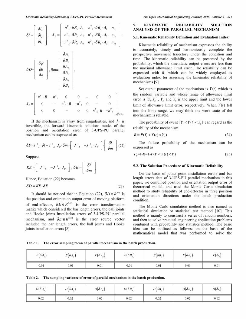
If the mechanism is away from singularities, and is invertible, the forward kinematic solutions model of the position and orientation error of 3-UPS-PU parallel mechanism can be expressed as
(22)
Suppose
,
Hence, Equation (22) becomes
(23)
It should be noticed that in Equation (22), is the position and orientation output error of moving platform of end-effector, is the error transformation matrix which considered the bar length errors, the ball joints and Hooke joints installation errors of 3-UPS-PU parallel mechanism, and is the error source vector included the bar length errors, the ball joints and Hooke joints installation errors [8].
5. KINEMATIC RELIABILITY SOLUTION ANALYSIS OF THE PARALLEL MECHANISM
5.1. Kinematic Reliability Definition and Evaluation Index
Kinematic reliability of mechanism expresses the ability to accurately, timely and harmoniously complete the prospective movement trajectory under the condition and time. The kinematic reliability can be presented by the probability, which the kinemtatic output errors are less than the maximal allowance limit error. The reliability can be expressed with R, which can be widely employed as evaluation index for assessing the kinematic reliability of mechanisms [9].
Set output parameter of the mechanism is Y (t) which is the random variable and whose range of allowance limit error is [Yl ,Yu ] , Yu and Yl is the upper limit and the lower limit of allowance limit error, respectively. When Y (t) fell into the limit range, we may think the work state of the mechanism is reliable.
The probability of event [Yl <Y (t) <Yu ] can regard as the reliability of the mechanism
R = P(Yl <Y (t) <Yu ) (24)
The failure probability of the mechanism can be expressed as
Pf =1-R=1-P(Y <Y (t) <Y ) (25)
5.2. The Solution Procedure of Kinematic Reliability
On the basis of joints point installation errors and bar length errors data of 3-UPS-PU parallel mechanism in this paper, we combined position and orientation output error of theoretical model, and used the Monte Carlo simulation method to study reliability of end-effector in three position and orientation directions under the batch production condition. The Monte Carlo simulation method is also named as statistical simulation or statistical test method [10]. This method is mainly to construct a series of random numbers, and then to solve practical engineering application problems combined with probability and statistics method. The basic idea can be outlined as follows: on the basis of the mathematical model that was performed to solve the
δ l =δ l1δ l2δ l3
⎡
⎣
⎢⎢⎢⎢
⎤
⎦
⎥⎥⎥⎥
JX =
nT1 ⋅δRx ⋅A1 nT1 ⋅δRy ⋅A1 n1znT 2 ⋅δRx ⋅A2 nT 2 ⋅δRy ⋅A2 n2znT 3 ⋅δRx ⋅A3 nT 3 ⋅δRy ⋅A3 n3z
⎡
⎣
⎢⎢⎢⎢
⎤
⎦
⎥⎥⎥⎥
δD=δψδθδh
⎡
⎣
⎢⎢⎢
⎤
⎦
⎥⎥⎥
δm=
δA1δB1δA2δB2δA3δB3
⎡
⎣
⎢⎢⎢⎢⎢⎢⎢⎢
⎤
⎦
⎥⎥⎥⎥⎥⎥⎥⎥
JP =
nT1 ⋅R −nT1 0 0 ⋅⋅⋅ 0 0
0 ⋅⋅⋅ nT 2 ⋅R −nT 2 0 ⋅⋅⋅ 0
0 0 ⋅⋅⋅ 0 0 nT 3 ⋅R −nT 3
⎡
⎣
⎢⎢⎢⎢
⎤
⎦
⎥⎥⎥⎥3×18( )
JX
δD=J −1X ⋅δ l − J
−1X ⋅ JP ⋅δm= J −1
X −J −1X ⋅ JP⎡
⎣⎢⎤⎦⎥ ⋅
δ lδm
⎡
⎣⎢
⎤
⎦⎥
KE = J −1X −J −1
X ⋅ JP⎡⎣⎢
⎤⎦⎥ δE = δ l
δm⎡
⎣⎢
⎤
⎦⎥
δD = KE ⋅δE
δD∈R3×1
KE ∈R3×21
δE ∈R21×1
Table 1. The error sampling mean of parallel mechanism in the batch production.
E δ Aix( )
E δ Aiy( )
E δ Aiz( )
E δ Bix( )
E δ Biy( )
E δ Biz( )
E δ li( )
0.01 0.01 0.01 0.01 0.01 0.01 0.01
Table 2. The sampling variance of error of parallel mechanism in the batch production.
D δ Aix( )
D δ Aiy( )
D δ Aiz( )
D δ Bix( )
D δ Biy( )
D δ Biz( )
D δ li( )
0.02 0.02 0.02 0.02 0.02 0.02 0.02

328 The Open Mechanical Engineering Journal, 2015, Volume 9 Cui et al.
practical problems, we construct stochastic simulation numbers of the model parameters, and then solve by sampling method. From that, we can get the probability value of the problem, or their digital features of random variables, whose standard variance of estimated value can be generally employed to measure the kinematic accuracy of the mechanism. Flow chart of kinematic reliability of 3-UPS-PU parallel mechanism can be described by applying Monte Carlo simulation method, as shown in Fig. (3). The process to solve kinematic reliability of 3-UPS-PU parallel mechanism in terms of Monte Carlo simulation method can be outlined as follows: (1) The sampling for each error
According to the distribution function of parallel mechanism joint point of installation errors and bar length errors,we can get the values of sampling error : xi (i = 1,2,3,,n) ;
(2) The solution of position and orientation output error at some given error information
We substitute the value of installation error of each joint point into each joint point vector, and bar length error into each driving limb formula. Then, we can solve the output error Δy according to the theoretical calculation model of position and orientation output error of the end-effector; (3) Repeating step (2)
According to the numbers of experiments and repeating step (2), we can obtain a group of position and orientation output errors, i.e. Δy1, Δy2, ⋅⋅⋅, Δyn , of the end-effector;
(4) The statistics of position and orientation output error
We can get the statistical results of position and orientation output errors, i.e. Δy1, Δy2 , ⋅⋅⋅, Δyn , and obtain the mean µ and stand variance δ . The next, we can solve kinematic reliability of the mechanism.
5.3. A Numerical Example Analysis
The structure parameters of 3-UPS-PU parallel mechanism are designed as ra = 300mm , rb = 500mm , h = 1200mm. It is notices that assume joints point installation and bar length errors obey the normal distribution when this spraying robot is in batch production. The mean and stand variance of the errors are related to the machining technology and processing condition. In this paper, we mainly provided a solution method of position and orientation output error and kinematic reliability with the consideration of joint point installation errors and bar length errors of the parallel mechanism [11-13]. The mean and standard variance of joint point installation errors and bar length errors are the same for brevity, as shown in Tables 1 and 2, respectively.
According to the given the mean and standard variance of errors. 30000 groups error data constructed by MATLAB
software which accord with normal distribution can be treated as an error sample of the mechanism. Then program can be easily implemented using MATLAB on the basis of position and orientation output error theoretical model of the mechanism [14, 15]. The position and orientation output error can be solved, and then the mean and standard variance can be calculated by mathematical statistics.
Finish
Theoretical error model
Sample bar length errors
Sample joints installation errors
Position and orientation error
Judge loop condition
Statistics
Reliability calculation
Theoretical error model
Start
N
Y
Fig. (3). The flow chart of kinematic reliability solution of 3-UPS-PU parallel mechanism.
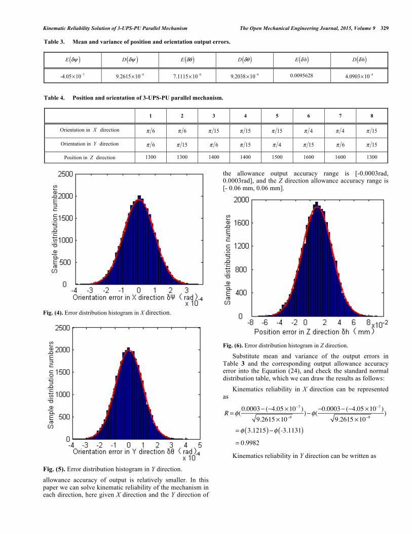
Given the position and orientation parameters of the moving platform: the X axis Angle ψ is π 36 , the Y axis Angle θ is π 18 and the Z axis location h is 1600 mm. Kinematic reliability of the mechanism was analyzed considering joint points installation errors and bar length errors in accord with normal distribution respectively when the mechanism in mass production. After 30000 times simulation experiments, sample distribution orientation errors and position errors of X axis, Y axis and Z axis can be plotted as shown in Figs. (4-6). The position and orientation error data in three output error directions of 3UPS-PU parallel mechanism were statically calculated adopting the Monte Carlo simulation method, and mean and variance of the errors in each direction are shown in Table 3. The kinematic reliability also has relationship with allowance output accuracy. The kinematic reliability will be higher when the range of allowance accuracy of output is bigger. And its reliability will be reduced when the range of
Kinematic Reliability Solution of 3-UPS-PU Parallel Mechanism The Open Mechanical Engineering Journal, 2015, Volume 9 329
Fig. (4). Error distribution histogram in X direction.
Fig. (5). Error distribution histogram in Y direction. allowance accuracy of output is relatively smaller. In this paper we can solve kinematic reliability of the mechanism in each direction, here given X direction and the Y direction of
the allowance output accuracy range is [-0.0003rad, 0.0003rad], and the Z direction allowance accuracy range is [- 0.06 mm, 0.06 mm].
Fig. (6). Error distribution histogram in Z direction.
Substitute mean and variance of the output errors in Table 3 and the corresponding output allowance accuracy error into the Equation (24), and check the standard normal distribution table, which we can draw the results as follows: Kinematics reliability in X direction can be represented as
R = φ(0.0003− (−4.05 ×10⁻⁷ )
9.2615 ×10⁻⁹)−φ(−0.0003− (−4.05 ×10
−7 )9.2615 ×10⁻⁹
)
= φ 3.1215( )−φ -3.1131( )= 0.9982
Kinematics reliability in Y direction can be written as
Table 3. Mean and variance of position and orientation output errors.
E δψ( )
D δψ( )
E δθ( )
D δθ( )
E δh( )
D δh( )
-4.05×10⁻⁷ 9.2615×10⁻⁹ 7.1115×10⁻⁹ 9.2038×10⁻⁹ 0.0095628 4.0903×10⁻⁴
Table 4. Position and orientation of 3-UPS-PU parallel mechanism.
1 2 3 4 5 6 7 8
Orientation in X direction π 6 π 6 π 15 π 15 π 15 π 4 π 4 π 15
Orientation in Y direction π 6 π 15 π 6 π 15 π 4 π 15 π 6 π 15
Position in Z direction 1300 1300 1400 1400 1500 1600 1600 1300

330 The Open Mechanical Engineering Journal, 2015, Volume 9 Cui et al.
R = φ(0.0003− (7.1115 ×10⁻⁹ )
9.2038 ×10⁻⁹)−φ(−0.0003− (7.1175 ×10
−9 )9.2038 ×10⁻⁹
)
= φ 3.1270( )−φ −3.1272( )= 0.9982
Kinematics reliability in Z direction can be described as
R = φ(0.06 − (0.0095628)4.0903×10⁻⁴
)−φ(−0.06 − (0.0095628)4.0903×10⁻⁴
)
= φ −0.4580( )−φ −0.4877( )= 0.9934
6. THE NUMERICAL SIMULATION VERIFICATION OF RELIABILITY SOLUTION
The kinematic reliability can be calculated not only included numerical complication but also MATLAB direct solution with command capaplot. Its principle is to select the data within the allowance accuracy range from the position and orientation output errors data, and calculate the probability within allowance accuracy range.
6.1. Reliability of MATLAB Solution
Now the kinematic reliability was analyzed in each direction. The error data and position and orientation parameters were the same as mentioned above. The kinematic reliabilities in X direction, in Y direction, and in Z direction are shown in Fig. (7) to Fig. (9), respectively.
Fig. (7). Kinematic reliability in X direction.
Fig. (8). Kinematic reliability in Y direction.
Fig. (9). Kinematic reliability in Z direction.
From the Figs. (7-9), we can see that the kinematic reliability data are basically coincident with the theoretical calculation results, which verify that the present method is specifically effective to some extent.
6.2. Comparison Between Theoretical Solution and MATLAB Solution
Kinematics reliability was obtained by comparing the method of 5.3 section theoretical solution with the method of 6.1 section MATLAB solution. Given eight-group parameters of the mechanism, as shown in Table 4. Kinematic reliability was solved under the eight-group position and orientation parameters by theoretical calculation and MATLAB solution, respectively. The final results are shown in Table 5. Curve can be connected directly with eight-group data which are obtained by theoretical calculation and MATLAB solution respectively. The results are shown in Figs. (10-12). From the figures above, we can see that the results of theoretical calculation and MATLAB calculation are basically coincident, which verify authenticity of MATLAB solution. Simultaneously, we obtain another method to solve the kinematic reliability of the parallel mechanism, quickly and efficiently.

Kinematic Reliability Solution of 3-UPS-PU Parallel Mechanism The Open Mechanical Engineering Journal, 2015, Volume 9 331
CONCLUSION
This paper mainly studied kinematics reliability of 3-UPS-PU parallel mechanisms, and finished the following several works: (1) The inverse kinematics solution model of 3-UPS-PU
parallel mechanism was established in terms of coordinate transformation theory, and the position and orientation error model of 3-UPS-PU parallel mechanism was derived by employing differential transformation method.
(2) The method of kinematic reliability of the mechanism was demonstrated by employing Monte Carlo simulation according to the position and orientation output error model established. Reliability analysis of the mechanism was performed further.
(3) Analysis and comparison of theoretical solution and MATLAB solution via the eight-group position and orientation of the 3-UPS-PU parallel mechanism can verify that the results are basically coincident. Therefore, we obtain a method to solve kinematics reliability of the parallel mechanism. Moreover, the methodology proposed here can be easily extended to the general parallel mechanism as well.
Fig. (10). Kinematic reliability comparison in X direction.
Fig. (11). Kinematic reliability comparison in Y direction.
0.91
0.96
1.01
1 2 3 4 5 6 7 8Kin
emat
ic re
liabi
lity
in Y
dire
ctio
nTheoretical calculationMATLAB solution
0.88
0.93
0.98
1.03
1 2 3 4 5 6 7 8
Kin
emat
ic re
liabi
lity
in X
dire
ctio
n
Theoretical calculationMATLAB solution
Table 5. Kinematic reliability of 3-UPS-PU parallel mechanism results comparison between theoretical solution and MATLAB solution.
Therapy
Matlab Reliability in X Direction Reliability in Y Direction Reliability in Z Direction
The first group 0.9559 0.9691 0.9873
0.95449 0.9691 0.98781
The second group 0.9807 0.9658 0.9863
0.97971 0.96707 0.9869
The third group 0.9755 0.9886 0.9934
0.97385 0.98876 0.99336
The fourth group 0.9888 0.9888 0.9924
0.98888 0.98778 0.99254
The fifth group 0.9199 0.9894 0.9938
0.9259 0.98935 0.99342
The sixth group 0.8932 0.9135 0.9772
0.89148 0.91392 0.97773
The seventh group 0.8905 0.9762 0.9869
0.89016 0.97676 0.98732
The eighth group 0.9874 0.9883 0.9924
0.98857 0.98763 0.99241

332 The Open Mechanical Engineering Journal, 2015, Volume 9 Cui et al.
Fig. (12). Kinematic reliability comparison in Z direction.
CONFLICT OF INTEREST
The author confirms that this article content has no conflict of interest.
ACKNOWLEDGMENTS
This research is supported by the National Natural Science Foundation of China (Grant No.51175143).
REFERENCES
[1] Q. Yang, Z. L. Sun, and M. Yan, “Kinematic reliability of improved delta parallel mechanism”, Acta Aeronautica et Astronautica Sinicavol, vol. 29, no. 2, pp. 487-491, 2008.
[2] A. P. Bowling, J. E. Renaud, and J. T. Newkirk, “Reliability-based design optimization of robotic system dynamic”, Journal of Mechanical Design, vol. 127, no. 4, pp. 449-454, 2007.
[3] H. Choid, H. Yooh, “Reliability analysis of a robot manipulator operation employing single Monte-Carlo simulation”, Key Engineering Materials, vol. 321-323, pp. 1568-1571, 2006.
[4] Y. M. Zhang, X.Z. Huang, and X.D. He, “Reliability-based Robust Design for kinematic accuracy of the shaper mechanism under
incomplete probability information”, Journal of Mechanical Engineering, vol. 45, no. 4, pp. 105-110, 2009.
[5] Z. L. Sun, Q. Yang, and M. Yan, “Simulation research on kinematics reliability of 3-RPS parallel robot”, Mechanical Science and Technology for Aerospace Engineering, vol. 26, no. 6, pp. 780-786, 2006.
[6] Y. B. Wang, P. Pessi, and H.P. Wu, “Accuracy analysis of hybrid parallel robot for the assembling of ITER”, Fusion Engineering and Design, vol. 84, pp. 1964-1968, 2009.
[7] S. M. Wang, F.E. Kornel, “Error model and accuracy analysis of a six-DOF Stewart platform”, Journal of Manufacturing Science and Engineering, vol. 124, no. 2, pp. 286-295, 2002.
[8] Q.S. Xu, Y.M. Li, “Error analysis and optimal design of a class of translational parallel kinematic machine using particle swarm optimization”, Robotica, vol. 27, no. 1, pp.67-78, 2009.
[9] A. P. Bowling, J. E. Renaud, and J. T. Newkirk, “Reliability-based design optimization of robotic system dynamic performance”, Journal of Mechanical Design, vol. 129, no. 4, pp. 449-454, 2007.
[10] D. H. Choi, H. H. Yoo, “Reliability analysis of a robot manipulator operation employing single Monte-Carlo simulation”, Key Engineering Materials, vol. 321-323, pp. 1568-1571, 2006.
[11] J.-W. Kim, C.-R. Shin, H.-S. Kim, and J.-H.Kyung, “Error model and kinematic calibration of a 5-axis hybrid machine tool”, SICE-ICASE International Joint Conference, Bexco, Busan, Korea, 2006, pp. 3111-31115.
[12] G. H. Cui, H. Q. Zhang, F. Xu and C.R. Sun, “Analysis of the kinematic accuracy reliability of a 3-DOF parallel robot manipulator”, Internal Journal of Advanced Robotic System, vol. 25, pp. 68-81, 2014.
[13] M. Daoud, Q. H. Mahmoud, “Mote Carlo simulation-based algorithms for estimating the reliability of mobile agent-based systems”, Journal of Network and Computer Application, vol. 31, pp. 19-21, 2008.
[14] R. Roshandel, “Calculating Architecture Reliability via Modeling and Analysis”, M.S. thesis, University of Southern California, 2006.
[15] D. C. Qin, Q. Zhu, H. X. Wu, and Z. F. Guo, “Analysis on motion precision reliability of hydraulic support”, Applied Mechanics and Materials, vol. 48-49, pp. 224-227, 2011.
Received: January 8, 2015 Revised: January 15, 2015 Accepted: January 16, 2015 © Cui et al.; Licensee Bentham Open.
This is an open access article licensed under the terms of the Creative Commons Attribution Non-Commercial License (http://creativecommons.org/licenses/by-nc/3.0/) which permits unrestricted, non-commercial use, distribution and reproduction in any medium, provided the work is properly cited.
0.9750.98
0.9850.99
0.995
1 2 3 4 5 6 7 8Kin
emat
ic re
liabi
lity
in Z
dire
ctio
n
Theoretical calculationMATLAB solution