kirchhoff's laws and circuit analysis (ec 2)
TRANSCRIPT

Kirchhoff's Laws and Circuit Analysis (EC 2) • Circuit analysis: solving for I and V at each element • Linear circuits: involve resistors, capacitors, inductors • Initial analysis uses only resistors • Power sources, constant voltage and current • Solved using Kirchhoff's Laws (Current and Voltage)

Circuit Nodes and Loops • Node: a point where several wires electrically connect • Symbolized by a dot or circle at the wire crossing • If wires cross without a dot, then not connected • Nodes also called junctions • Typically give nodes a number or letter
• Branches: lines with devices connecting two nodes • Loop: an independent closed path in a circuit • There may be several possible closed paths

Kirchhoff's Current Law (KCL) • Kirchhoff's Current Law (KCL) • The algebraic sum of currents entering any node (junction) is zero
01
=∑=
N
jjI
where N = number of lines entering the node • NOTE: the sign convention: • Currents are positive when they entering the node • Currents negative when leaving • Or the reverse of this.
KCL is called a Continuity Equation: It says current is not created or destroyed at any node

Example of Kirchhoff's Current Law (KCL) • Consider the simple parallel resistances below • At node 1 define current positive into resistors • Since V on R1 = 5V the current is
mARVI 5
10005
11 ===
• Same V on R2 = 5V the current is
mARVI 1
50005
22 ===
• Thus by KCL at node 1
0001.0005.0 3321 =++=++ IIII
• Thus the total current is
mAIII 6213 −=−−=
• Node 2 has the negatives of these values

Kirchhoff's Voltage Law (KVL) • Kirchhoff's Voltage Law (KVL) • Algebraic sum of the voltage drops around any loop or circuit = 0
01
=∑=
N
jjV
where N = number of voltage drops • NOTE: the sign convention • Voltage drops are positive in the direction of the set loop current • Voltage drops negative when opposite loop current • Voltage sources positive if current flows out of + side • Voltage sources negative if current flows into + side
• A loop is an independent closed path in the circuit • Define a "loop current" along that path • Real currents may be made up of several loop currents
211 IIIR −=

Example Kirchhoff's Voltage Law (KVL) Consider a simple one loop circuit Voltages are numbered by the element name eg. V1 or VR1 : voltage across R1 Going around loop 1 in the loop direction Recall by the rules: • Voltage drops negative when opposite loop current. • Voltage sources positive if current flows out of + side
01 =−VV s
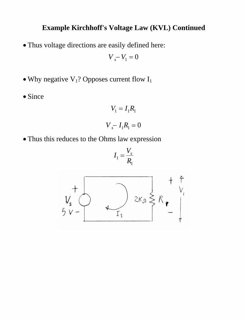
Example Kirchhoff's Voltage Law (KVL) Continued • Thus voltage directions are easily defined here:
01 =−VV s
• Why negative V1? Opposes current flow I1 • Since
111 RIV =
011 =− RIV s
• Thus this reduces to the Ohms law expression
11 R
VI s=

KVL Example Resistor Voltage Divider • Consider a series of resistors and a voltage source • Then using KVL
021 =−− VVV
• Since by Ohm’s law
212111 RIVRIV ==
• Then
( ) 02112111 =+−=−− RRIVRIRIV
• Thus
mARR
VI 130002000
521
1 =+
=+
=
• i.e. get the resistors in series formula
Ω=+= KRRRtotal 521

KVL Example Resistor Voltage Divider Continued • What is the voltage across each resistor? • Now we can relate V1 and V2 to the applied V • With the substitution
211 RR
VI+
=
• Thus V1
VRR
VRRIV 230002000
)2000(521
1111 =
+=
+==
• Similarly for the V2
VRR
VRRIV 330002000
)3000(521
2211 =
+=
+==

KVL and KCL for Different Circuits • With multiple voltage sources best to use KVL • Can write KVL equation for each loop
• With multiple current sources best to use KCL • Can write KCL equations at each node.
• In practice can solve whole circuit with either method

Resistors in Series (EC3) • Resistors in series add to give the total resistance
∑=
=N
jjtotal RR
1
• Example: total of 1, 2, and 3 Kohm resistors in series
• Thus total is
Ω=++=++= KRRRRtotal 6300020001000321
• Resistors in series law comes directly from KVL

Resistors in Parallel • Resistors in parallel: • Inverse of the total equals the sum of the inverses
∑=
=N
j jtotal RR 1
11
This comes directly from KCL at the node
∑∑==
===N
j j
N
jj
totaltotal R
VIRVI
11
• NOTE: inverse of resistance called conductance (G) • Units are mhos (ohms spelled backwards)
∑=
=N
jjtotal GG
1
• Thus when work in conductance change parallel to series equations

Example Parallel Resistors Example 1K and 2K resistors in parallel
20000003000
20001
1000111
1=+==∑
=
N
j jtotal RR
Ω= 666totalR

Example Parallel Resistors • Example: two 1 Kohm resistors in parallel
Ω==+==∑=
5001000
21000
11000
1111
total
N
j jtotal
RorRR
KK
• Thus adding N same resistors cuts get
NRRtotal =
• Good way to get lower R values