kit number 8052300 & 8052310 cub cadet electric steering ... · 656600 page 1 kit number...
TRANSCRIPT
656600 Page 1
KIT NUMBER 8052300 & 8052310
Cub Cadet Electric Steering Installation Manual
Thank you for purchasing our ELECTRA-STEER 12v electric assist power steering system. Please carefully read this instruction sheet entirely before you begin to install the system. Remember, before beginning installation, insure that you are in a level well lit, organized, work area. Engage the parking brake, disconnect the battery until power is needed and chock or block the rear wheels to insure the vehicle is stable.
656600 Page 2
INSTALLATION TIPS:
Due to minor variations in vehicle frames, we recommend that you leave all the U-Joint pinch bolts loose until the motor is mounted. Then rock the steering wheel back and forth to allow the U-Joints to align themselves. Complete the installation by tightening these bolts.
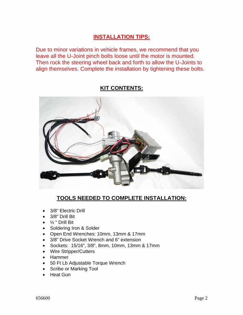
KIT CONTENTS:
TOOLS NEEDED TO COMPLETE INSTALLATION:
3/8” Electric Drill 3/8” Drill Bit ½ “ Drill Bit Soldering Iron & Solder Open End Wrenches: 10mm, 13mm & 17mm 3/8” Drive Socket Wrench and 6” extension Sockets: 15/16”, 3/8”, 8mm, 10mm, 13mm & 17mm Wire Stripper/Cutters Hammer 50 Ft Lb Adjustable Torque Wrench Scribe or Marking Tool Heat Gun
656600 Page 3
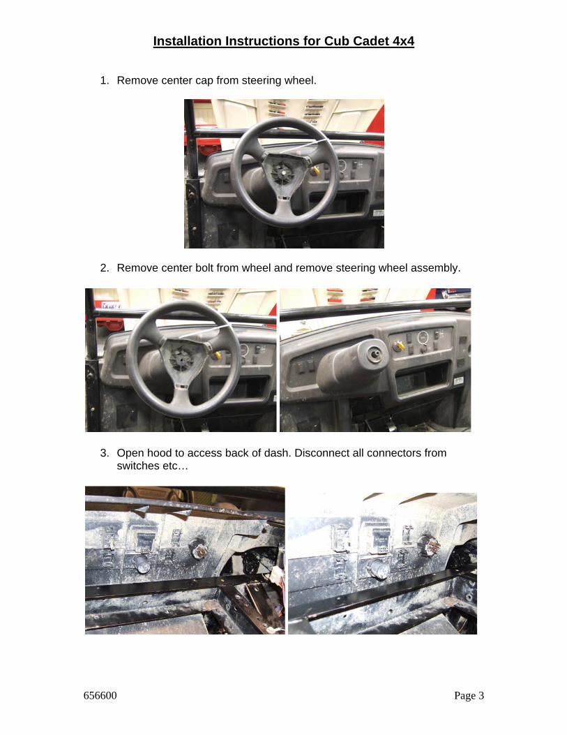
Installation Instructions for Cub Cadet 4x4
1. Remove center cap from steering wheel.
2. Remove center bolt from wheel and remove steering wheel assembly.
3. Open hood to access back of dash. Disconnect all connectors from switches etc…
656600 Page 4
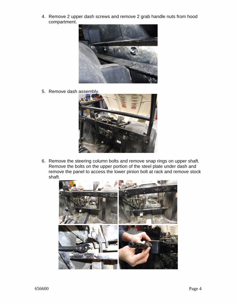
4. Remove 2 upper dash screws and remove 2 grab handle nuts from hood compartment.
5. Remove dash assembly.
6. Remove the steering column bolts and remove snap rings on upper shaft. Remove the bolts on the upper portion of the steel plate under dash and remove the panel to access the lower pinion bolt at rack and remove stock shaft.
656600 Page 5
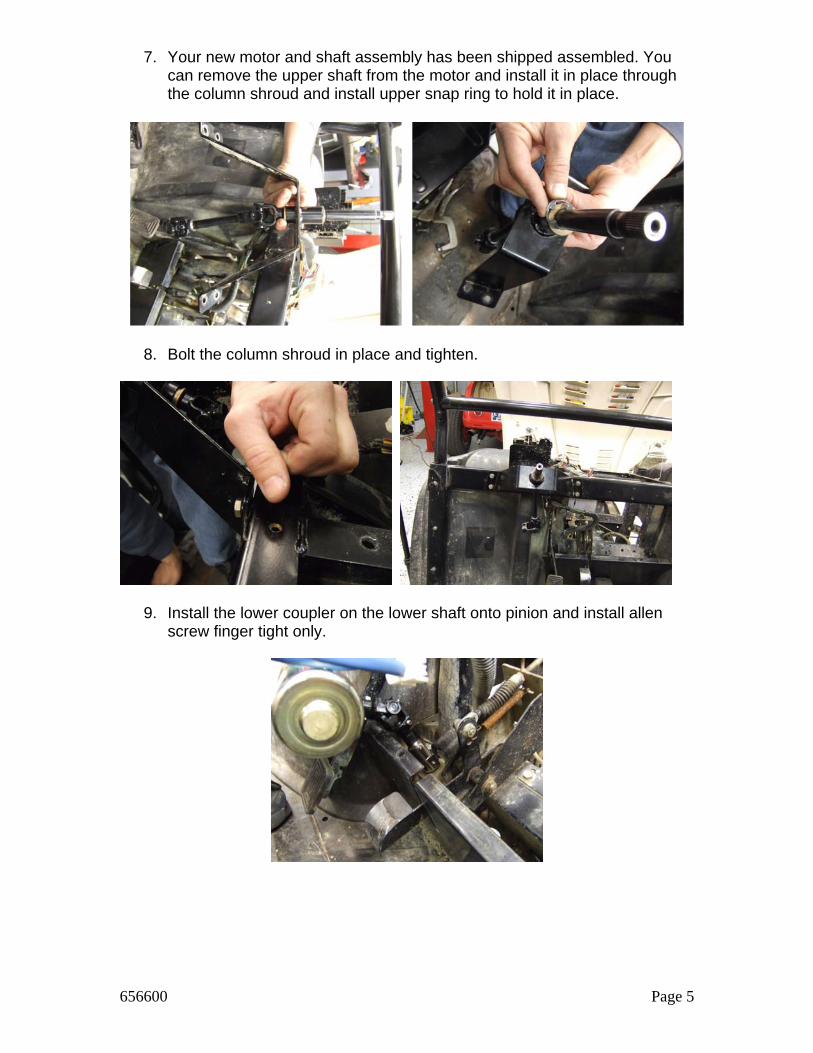
7. Your new motor and shaft assembly has been shipped assembled. You can remove the upper shaft from the motor and install it in place through the column shroud and install upper snap ring to hold it in place.
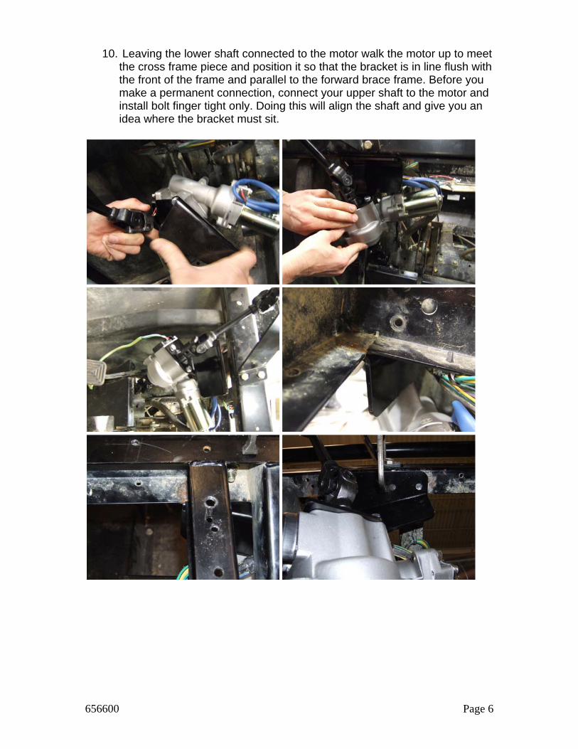
8. Bolt the column shroud in place and tighten.
9. Install the lower coupler on the lower shaft onto pinion and install allen screw finger tight only.
656600 Page 6
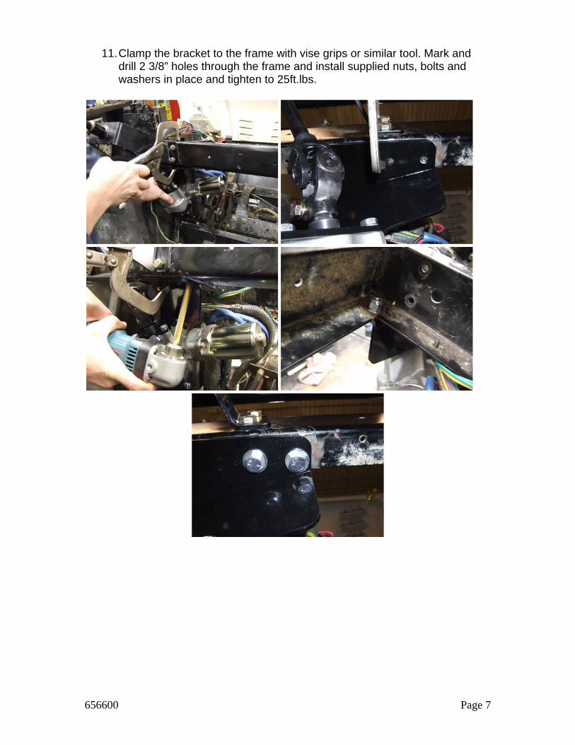
10. Leaving the lower shaft connected to the motor walk the motor up to meet
the cross frame piece and position it so that the bracket is in line flush with the front of the frame and parallel to the forward brace frame. Before you make a permanent connection, connect your upper shaft to the motor and install bolt finger tight only. Doing this will align the shaft and give you an idea where the bracket must sit.
656600 Page 7
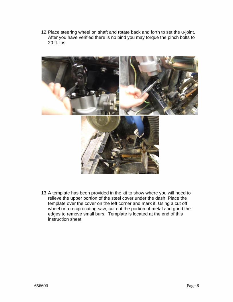
11. Clamp the bracket to the frame with vise grips or similar tool. Mark and
drill 2 3/8” holes through the frame and install supplied nuts, bolts and washers in place and tighten to 25ft.lbs.
656600 Page 8
12. Place steering wheel on shaft and rotate back and forth to set the u-joint.
After you have verified there is no bind you may torque the pinch bolts to 20 ft. lbs.
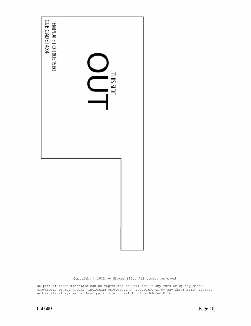
13. A template has been provided in the kit to show where you will need to relieve the upper portion of the steel cover under the dash. Place the template over the cover on the left corner and mark it. Using a cut off wheel or a reciprocating saw, cut out the portion of metal and grind the edges to remove small burs. Template is located at the end of this instruction sheet.
656600 Page 9
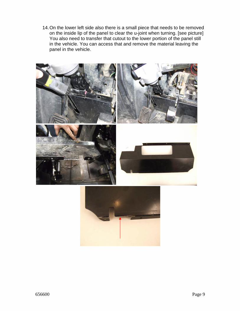
14. On the lower left side also there is a small piece that needs to be removed on the inside lip of the panel to clear the u-joint when turning. [see picture] You also need to transfer that cutout to the lower portion of the panel still in the vehicle. You can access that and remove the material leaving the panel in the vehicle.
656600 Page 10
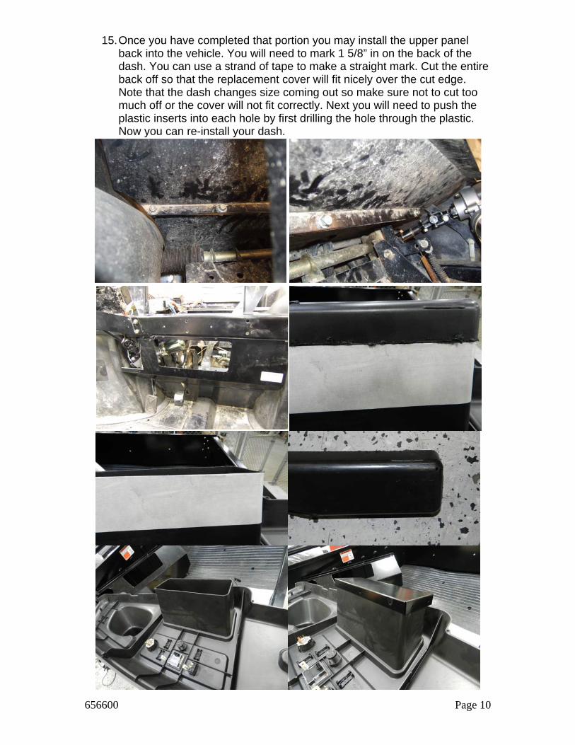
15. Once you have completed that portion you may install the upper panel back into the vehicle. You will need to mark 1 5/8” in on the back of the dash. You can use a strand of tape to make a straight mark. Cut the entire back off so that the replacement cover will fit nicely over the cut edge. Note that the dash changes size coming out so make sure not to cut too much off or the cover will not fit correctly. Next you will need to push the plastic inserts into each hole by first drilling the hole through the plastic. Now you can re-install your dash.
656600 Page 11
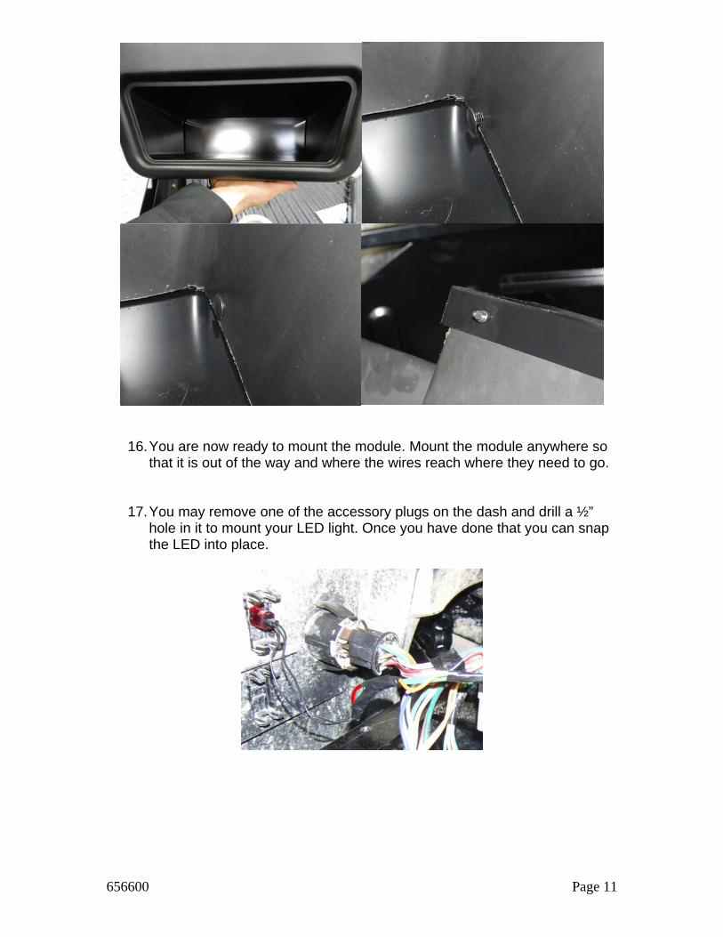
16. You are now ready to mount the module. Mount the module anywhere so that it is out of the way and where the wires reach where they need to go.
17. You may remove one of the accessory plugs on the dash and drill a ½” hole in it to mount your LED light. Once you have done that you can snap the LED into place.
656600 Page 12
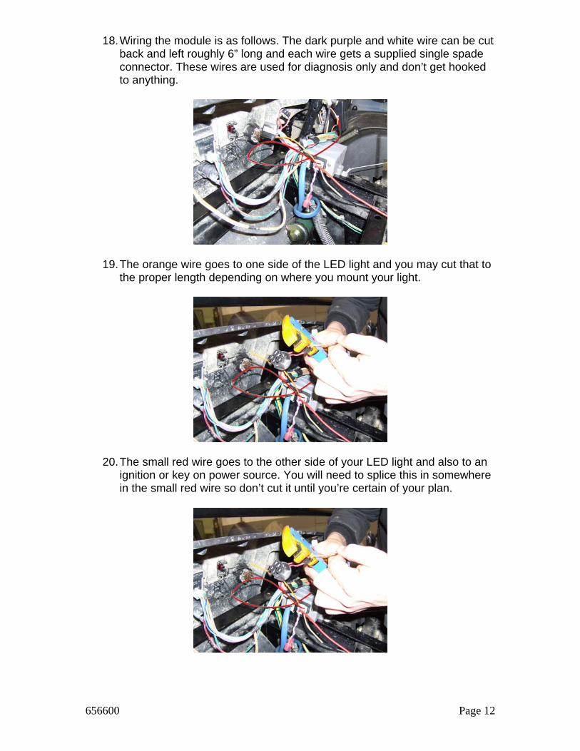
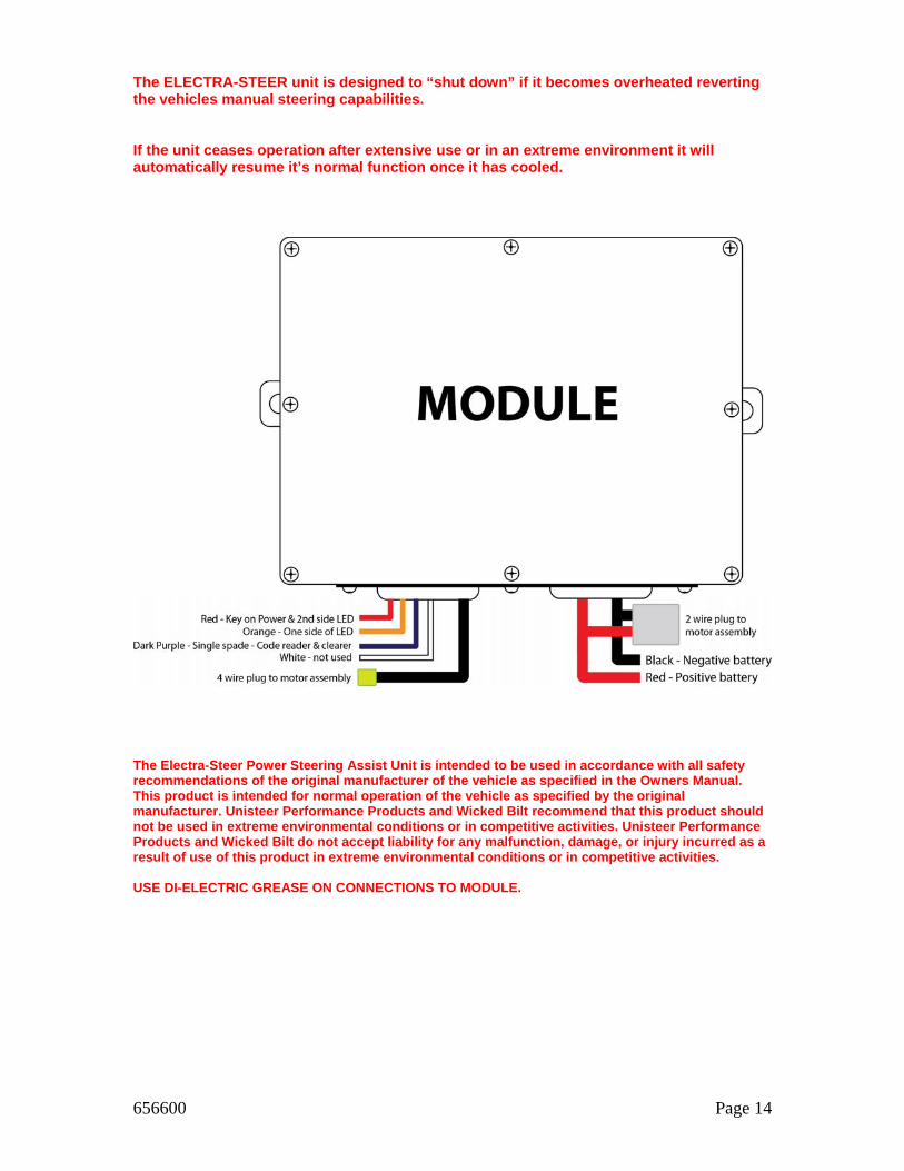
18. Wiring the module is as follows. The dark purple and white wire can be cut back and left roughly 6” long and each wire gets a supplied single spade connector. These wires are used for diagnosis only and don’t get hooked to anything.
19. The orange wire goes to one side of the LED light and you may cut that to the proper length depending on where you mount your light.
20. The small red wire goes to the other side of your LED light and also to an ignition or key on power source. You will need to splice this in somewhere in the small red wire so don’t cut it until you’re certain of your plan.
656600 Page 13
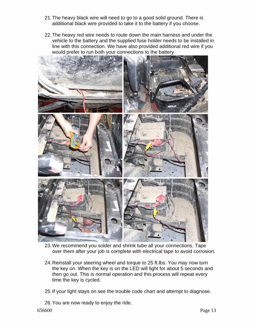
21. The heavy black wire will need to go to a good solid ground. There is additional black wire provided to take it to the battery if you choose.
22. The heavy red wire needs to route down the main harness and under the vehicle to the battery and the supplied fuse holder needs to be installed in line with this connection. We have also provided additional red wire if you would prefer to run both your connections to the battery.
23. We recommend you solder and shrink tube all your connections. Tape
over them after your job is complete with electrical tape to avoid corrosion.
24. Reinstall your steering wheel and torque to 25 ft.lbs. You may now turn the key on. When the key is on the LED will light for about 5 seconds and then go out. This is normal operation and this process will repeat every time the key is cycled.
25. If your light stays on see the trouble code chart and attempt to diagnose.
26. You are now ready to enjoy the ride.
656600 Page 14
The ELECTRA-STEER unit is designed to “shut down” if it becomes overheated reverting the vehicles manual steering capabilities. If the unit ceases operation after extensive use or in an extreme environment it will automatically resume it’s normal function once it has cooled.
The Electra-Steer Power Steering Assist Unit is intended to be used in accordance with all safety recommendations of the original manufacturer of the vehicle as specified in the Owners Manual. This product is intended for normal operation of the vehicle as specified by the original manufacturer. Unisteer Performance Products and Wicked Bilt recommend that this product should not be used in extreme environmental conditions or in competitive activities. Unisteer Performance Products and Wicked Bilt do not accept liability for any malfunction, damage, or injury incurred as a result of use of this product in extreme environmental conditions or in competitive activities. USE DI-ELECTRIC GREASE ON CONNECTIONS TO MODULE.
656600 Page 15
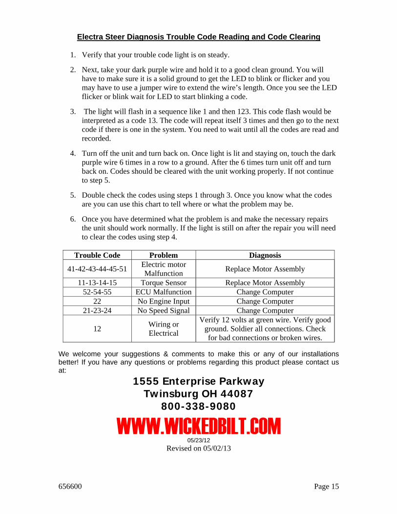
Electra Steer Diagnosis Trouble Code Reading and Code Clearing
1. Verify that your trouble code light is on steady.
2. Next, take your dark purple wire and hold it to a good clean ground. You will have to make sure it is a solid ground to get the LED to blink or flicker and you may have to use a jumper wire to extend the wire’s length. Once you see the LED flicker or blink wait for LED to start blinking a code.
3. The light will flash in a sequence like 1 and then 123. This code flash would be interpreted as a code 13. The code will repeat itself 3 times and then go to the next code if there is one in the system. You need to wait until all the codes are read and recorded.
4. Turn off the unit and turn back on. Once light is lit and staying on, touch the dark purple wire 6 times in a row to a ground. After the 6 times turn unit off and turn back on. Codes should be cleared with the unit working properly. If not continue to step 5.
5. Double check the codes using steps 1 through 3. Once you know what the codes are you can use this chart to tell where or what the problem may be.
6. Once you have determined what the problem is and make the necessary repairs the unit should work normally. If the light is still on after the repair you will need to clear the codes using step 4.
Trouble Code Problem Diagnosis
41-42-43-44-45-51 Electric motor Malfunction
Replace Motor Assembly
11-13-14-15 Torque Sensor Replace Motor Assembly 52-54-55 ECU Malfunction Change Computer
22 No Engine Input Change Computer 21-23-24 No Speed Signal Change Computer
12 Wiring or Electrical
Verify 12 volts at green wire. Verify good ground. Soldier all connections. Check for bad connections or broken wires.
We welcome your suggestions & comments to make this or any of our installations better! If you have any questions or problems regarding this product please contact us at:
1555 Enterprise Parkway Twinsburg OH 44087
800-338-9080
WWW.WICKEDBILT.COM 05/23/12
Revised on 05/02/13
656600 Page 16
Copyright © 2012 by Wicked Bilt. All rights reserved.
No part of these materials can be reproduced or utilized in any form or by any means, electronic or mechanical, including photocopying, recording or by any information storage and retrieval system, without permission in writing from Wicked Bilt.