kit packing c7 vette pump w/4 feet shielded cable...1/8 t fitting ____ 4 inch –4-4 hose 6 inch...
TRANSCRIPT
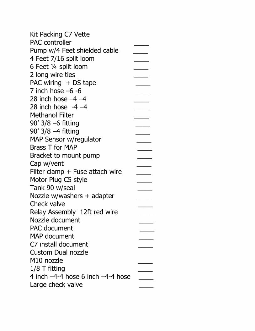
Kit Packing C7 Vette PAC controller ____ Pump w/4 Feet shielded cable ____ 4 Feet 7/16 split loom ____ 6 Feet ¼ split loom ____ 2 long wire ties ____ PAC wiring + DS tape ____ 7 inch hose –6 -6 ____ 28 inch hose –4 –4 ____ 28 inch hose -4 –4 ____ Methanol Filter ____ 90’ 3/8 –6 fitting ____ 90’ 3/8 –4 fitting ____ MAP Sensor w/regulator ____ Brass T for MAP ____ Bracket to mount pump ____ Cap w/vent ____ Filter clamp + Fuse attach wire ____ Motor Plug C5 style ____ Tank 90 w/seal ____ Nozzle w/washers + adapter ____ Check valve ____ Relay Assembly 12ft red wire ____ Nozzle document ____ PAC document ____ MAP document ____ C7 install document ____ Custom Dual nozzle M10 nozzle ____ 1/8 T fitting ____ 4 inch –4-4 hose 6 inch –4-4 hose ____ Large check valve ____

General Disclaimer: The use of this system is for Off-Road use only. It is intended for racing on a closed course under supervision. Under no circumstance will Alkycontrol INC be liable for any damages stemming from the use of this product. Use at your own risk. Observe posted speed limit signs. Use common sense. Handle fluids being used with the system with care. What fluid to use? The tuner will setup what is the best fluid given the particular goals trying to be achieved. It is important to follow they’re recommendation and whatever fluid the engine was tuned at, must be used as it can affect air fuel ratios the engine operates at under load. Service.. The pumps are re-buildable. The higher the concentration of methanol used with the system, the shorter its life. Water should last 15 years. Straight methanol 2-3 years typically. Before seals harden and a rebuild is necessitated. Typically the turn-on LED will degrade in the way it switches from Red to Green. Meaning delayed in building pressure. Questions.. If you have any question on the operation of the system, please consult the shop that installed and tuned the system. Or you can call us for any concern.

Alky Pump install Important notes… Do Not Mount pump with head facing upwards as this will allow water to collect inside sleeve and ruin motor. Please install as pictured, It can also be installed horizontally as long as the pitch does not allow water to collect in sleeve. Any question.. please call 813-265-1400 Julio

C7 Corvette installation instructions
1) The pump installation You first need to gain access to the tank by dropping the drivers side inner fender.
There are some clips you need to remove using a flat screwdriver, you will also need to unsnap a molding on the drivers side fender to gain access to a few T15 torx fasteners.
Once the inner fender liner is removed, you will note the factory reservoir. Next I pull the motor out from the reservoir and unsnap its electrical connector. Water will come out of reservoir. Once the tank has drained, I drill a 7/8 diameter hole into the bottom
of the reservoir behind where the factory motor was installed.

I use a Uni-Bit that its largest size is 7/8. These are available from most hardware stores. Harbor Freight as well. Try and get any slivers of plastic as the hole is drilled.
Then put grommet into hole, lube WD40 the grommet and push the barb in facing forward. At this point install the grommet into the washer motor hole, and push the
barb in to seal it.
Next is we need to get the pump cable into the cockpit of the car. On the drivers side kick panel there is a rubber grommet which provides perfect access.
I used an Xacto knife and put a small slit into the rubber to run wires through it. At this point a fish or coat hanger wire works great, run the fish out through the lubed
grommet and attach end of pump cable to it using electrical tape. You’ll note the plastic tubing I also ran on this install for the boost reference. Once you have the pump cable
and boost source situated under the dash, we can get back to mounting the pump.
Reason I ran the wire first was access. With the pump in place, there is less space to fish the pump cable.

Now the pump we need to attach the supplied steel bracket and get rid of the mounting
plate it has. Once the bracket is mounted to pump, install the 90 degree pump fittings in by hand. Note the inlet fitting will face towards the frame and the outlet fitting will
point straight up. I feed the 28 inch hose from the top of the drivers fender by the brake boosterand now thread it onto the outlet fitting. Tighten it as access will be hard
once pump is set in place. Now pull wire loom off and use the supplied ¼ bolt to bolt the pump to the wire loom hole. Next is install the feed hose and tighten its fittings. Remember these fittings are soft brass. Don’t force them more than needed.

Next is attach the white wire to a chassis ground. A simple 5/16 self tapping screw to
the plate handles this. Plug the pump harness into the pump. We are done with the inner fender portion of the install.
2) Filter and Nozzle
The filter has an arrow. It indicates flow direction. It goes in the pressure side
between the 2 28 inch supplied hoses. And uses the clamp to mount to a suitable location.

The nozzle goes installed in the charge pipe after the MAF sensor. Not before. *Note
this particular picture shows an IAT Breakout Kit added.
To do so, first is mark where the hole will be before removing the charge pipe. Next is
drill hole into charge tube 3/8 diameter and clean up the hole from debris. The nozzle has two washers included. If nozzles are going into aluminum, the rubber washers help seal the nozzle.
First step is you must have a washer on the inside. Period. Next is insert threads from
the inside out and by hand attach the elbow. This will pull threads out more. Remove elbow, next is install washer on the outside so it creates a sandwich with the mounting surface. Start to tighten.. once some threads are now in the elbow, back it out and use
red/blue Loctite on the threads and install elbow again until it is snug. The trick is you don’t want the nozzle tip to bottom out on the elbow. Next is put some Loctite on the threads of the check valve supplied (single nozzle), and
apply some Loctite to the adapter that threads into the check valve. Attach 28 inch hose from filter to nozzle. Your done with this part. Next is install cap onto reservoir

and fill tank with liquid being used. IE methanol. Check for leaks. If none.. you may go ahead and install the inner fender and put the wheel back on the car.
Only other under-hood issue you may have is attaching the boost line reference. This
concludes the under-hood portion.
3) Relay The relay will be installed in the rear of the car by the fuse box. It has 4 wires, red
with an O-ring goes to the power lug, long red wire goes to red spade terminal on controller. Gray goes to trigger on fuse box. And black goes to ground. I used one of
the subwoofer box studs to secure it in place.
Gray attaches to the yellow fuse using the supplied “tap” with gray wire. Some shops will prefer to install the PAC controller in the rear of the car, in my example I installed it
under the drivers side dash. This is personal preference. These instructions pertain to doing the install under the drivers side dash. Wiring is the same.
At this point relay is now wired and the red wire is run through the back drivers side and down the rocker panel. The panels simply unsnap on the C7 making it easy.

4) PAC wiring
Under the drivers side sill plate you will note the main grounds. Perfect place to
attach the black wire from the PAC controller4. I also used this ground for the black wire from the 2 bar MAP sensor.


The LED for turnon must be mounted in a visible location, one option is drilling a small hole using a ¼ drill and mounting in in the dash.

A less intrusive location is to use some heat shrink and mount it right above the vent as shown below.
At this point I have the pump cable under the dash, the LED wires, the map sensor,
and the controller.

5) Under Dash wiring
This maybe a good time to take a break, wash hands, the easy part begins.
This is just guidelines from numerous installations I have done. The sky is the limit on
creativity, and this should only be used as reference for what I have done, has been easy, and has worked.
Important note: The Turn-on LED is not resistor protected. Do not connect to 12v. Not even for a split second.
The first thing I always do is visually place where the location of the “turn-on” LED will be located. Typically this will be near your boost gauge or wideband gauge. The
purpose of this LED is to indicate when the system has reached its turn-on threshold based on the signal from the MAP sensor(Red). And when the pump switch has moved
indicating pressure (Green)(<50 PSI). It must be somewhere easily seen.
The red wire coming from the relay will go the larger red wire with spade terminal on the PAC. Simply cut the spade off and splice the wires together. Solder and heat shrink recommended.
Next is attach the orange wire from the turn-on led to the orange wire coming
from the controller, brown wire to brown wire.
Attach the red and green wire from the MAP to the red and green wire on the PAC controller. The violet/gray wire leave alone until latter.
And finally the pump connections. Cut the wire to length and strip approx 3-4 inches of insulation from the wire. Remove foil. Then strip about ½ inch of insulation on the red
and black wires that lead to the pump.

PAC terminal wiring instructions The following pictures show how to connect the pump cable wiring to the PAC controller.
Tools needed
1)Heavy duty set of crimpers(available through Home Depot, NAPA, Sears, Klein, Blue-Point, etc.) Do Not Use Cheap made in China crimpers….
2)Razor blade
3)Heat gun or lighter

Step 1 Strip insulation from end of pump cable and separate wires. Note there are three wires.
Red, Black, bare wire. Strip insulation Red and black wires. About ¼ inch is fine. And use the small supplied Male spade terminals. Crimp the terminals from the bottom as
shown.
Step 2 Slide large black heat-shrink over terminals and cable. Next is slide white heat-shrink
over Bare wire, slide Red heat-shrink over Red wire. Slide Black heat-shrink over Black wire. Then push male spades into their respective colored female connectors as shown. Next is slide heat-shrink over terminals.

Step 3 Apply heat to the heat-shrink.
Step4 Slide large heat-shrink over entire connections
Step 5 In the event more than one wire will be attached to the Red wire. Example Map sensor
regulator, use the larger supplied Male spade that can accommodate larger wire and assemble as stated above.
I mounted the PAC controller up and behind the dash above the hood release cables. The MAP sensor in my case also was installed there. In my particular case I connected
the hose on the MAP sensor to the plastic tube I ran earlier with the pump cable.

7) The gray/violet wire
Be careful on how this wire is to be used, most applications will not benefit from it being connected. Here’s the principle and connectivity. The violet wire
while a ground is applied will limit the pressure output of the system. And its only use is to help assist with spool-up while brake torque is applied to spool the turbo in a racing
application. So here are some ideas and methods to connect the wire for this feature to be present.
Simplest method is a momentary toggle switch in the ashtray whereby one leg of the switch goes to ground, the other to the violet wire. While staging the car, depress the
switch and build boost.. As soon as the car launches release the switch and the system goes back to normal.
Next is to wire a relay to activate while the brake is being depressed. To do so, wire the Bosch 30 amp automotive relay as follows. Terminal 85 to the blue wire with stripe on
the brake pedal switch. Terminal 86 on the relay and terminal 87 on the relay to chassis ground. Terminal 30 to violet. When the brakes are applied, the relay “clicks” thus
applying a ground to the violet wire. The gray wire can be used to trigger an auxillary system. In case a solenoid or other
device requires a signal once the system activates.
Typically these wires are not used.
8) Final
At this point you’ve concluded the installation, first thing to do is before putting alcohol/water into the tank, is start engine and set the blue gain knob to the middle position. Next depress the black test button and observe the turn-on LED next to the
boost gauge lights up red. At this point observe the low washer fluid lamp, which should also be lit if the tank is empty. If everything checks ok, fill the tank with
alcohol/water, and check for leaks coming from fittings that may have not been tightened. Start the vehicle, place gain on position 8, and push and hold the test button. Observe the turn-on LED illuminates red, then goes green since pressure now
has been established. Motor should also stumble. NOTE>>> on twin nozzle systems LED will not go GREEN on TEST.

If these tests are passed, then your ready for a road check. And on your maiden voyage bring the boost up slowly and as the gauge goes past 4 PSI boost, the turn-on
LED will illuminate. If it doesn’t, do not continue the test and see why the MAP sensor isn’t working. This is very important.
If it does work correctly, then proceed to increase the boost level observing how the
engine feels and assure there is no surging when the system is spraying. If this part is passed, watch your knock readings, and roll into the throttle to your desired boost level. Stabbing the throttle on some cars can induce false knock. Just trying to make sure
what you see is real or false. Also observe the turn-on LED and it will change color from red to green when initial pressure is developed. This can be changed via the adjusting
screw on top of the pump. Outward decreases activation pressure, inward.. increases it. Typically I will set so it comes on early on. You may find our setting to be acceptable. Adjusting this screw has no affect on the system or its delivery. Its for changing when
the LED indicator flips color.
From this point fine tuning of the system can be performed.
9) Fine tuning Although most cars will work with the system setup as is from factory default settings,
this is just a guideline. With the gain knob(blue) turned to minimum, you should see some knock but not a whole lot. Typically less than 2 degrees at WOT. Increasing the
gain knob should make the motor go to zero knock. If your setting is at minimum and you don’t see any knock, you may have too much alcohol being sprayed. The
adjustment that affects this is the knob inside the PAC controller labeled “INITIAL”. Turning this screw counterclockwise reduces the ramp and puts less alcohol/water into the motor. Small adjustments make big changes. Repeat the procedure until the motor
just has enough alcohol to curb the detonation, but not too much.
On certain applications, whereby chip/fueling is adjustable, it may be beneficial to increase the initial and lower the fueling whereby upping the flow of alcohol through
the motor. Individual results may vary, enjoy the product.
10) Contact
If any part of this procedure is unclear, or issue arises, please contact me or the vendor for assistance. Also note there are installation pictures available
on my web site www.alkycontrol.com . It would be my pleasure in helping you make the car go fast and stay together.
Julio Don 1-813-265-1400 email: [email protected]

www.alkycontrol.com
PAC- Progressive Alcohol Controller
Introduction
The PAC is a versatile electronic motor controller using pulse width modulation technology. It
allows the user to custom tailor voltage output to the injection pump being used so that it
increases pressure with the increase in voltage output coming from the vehicle MAP sensor.
Recommended that vehicle have a 3 bar map sensor for better voltage control. Will support any
injection pump rated up to 15 amps.
Features
Added flexibility to the control of an injection pump to overcome boost pressure in intake tract,
ability to run higher pressures from an injection pump without inducing flooding or transitional
knock, input terminal for pressure reduction(brake input), ability to custom tailor installation,
ease of use, and flexibility. Built in fuse.
Unpacking
Included in the kit should be enough wiring and connectors to do a full install. This is a list of
what is included. Controller, 12 feet 16 gauge shielded cable, 12 feet ¼ inch loom, 4 red splices,
8 wire ties, 3 spade terminals, one LED, solder, and some heat shrink tubing.
Tools Required/Recommended Connector crimper.. Klein, Blue point, etc. , soldering iron or gun with 60/40 solder, drill with
unibit drill bit, 12V test lite, heat gun, basic hand tools, and a digital voltmeter.
6
Installation These are general guidelines for component installation. The kit comprises of two individual
modules. They are the main controller, and the remote controller. A RED and a Black weather
pack connector is used to supply power to the main controller. The Red goes to a switched
ignition source capable of handling 15 amps. I use the IGN terminal on a GM fuse block. Or this
can be routed from a relay activated by the ignition switch. Black goes to chassis ground. The
connections to the injection pump are the Red/Black/White wires coming from the main
controller. Connections to these using the supplied spade connectors. Red wire to from the pump
to Red wire from main controller. Black wire from pump to Black wire from main controller.
There is a “drain/silver/bare” wire for the pressure sensing, this will be connected to the White
terminal. It is highly recommended that these connections be soldered to assure reliable
connections.
IMPORTANT NOTE: The “Black Pump Wire” on the main controller is not a ground.
Main controller wiring, green-violet-gray-orange-brown.

Green is connected to the MAP sensor signal wire. On in the case of Ford vehicles.. MAF
Gray is an auxillary output that will switch + voltage when system activates. Examples to run a
solenoid driver relay module, input to external boost controller, etc.. typically not used
Orange/Brown twisted go to the Turn-on LED. These wires will flip polarity when pressure is
developed. Suggestion is to place turn-on LED near boost gauge to indicate
system has activated.
Violet wire is the negative trigger input terminal for pump speed
reduction. Grounding this wire reduces injection pump speed to initial pump pressure for staging
applications while drag racing. Intended application are E-brake switches.
The remote controller affords the user the flexibility of custom installing controls with dash
panels of vehicles or attaching control box as is. For custom installation, simply remove screws
from box and relocate controls and LED. A small jewelers screwdriver will be required to
remove knob assembly. Unibit drill bit makes graduated drilling holes a snap.
Setup and Use The remote controller features a knob that controls ON/OFF and GAIN. The LED next to it
indicates system is armed and the push button applies “initial” pump speed to the pump for
testing operation.
On the main controller is an access door. Opening the access door reveals two controls internally
labeled “TURN-ON” and “INITIAL”. The turn-on control allows the user to set a turn-on
voltage from 1.7volts to 5volts. Clockwise rotation increases the voltage needed to trigger
system. The “INITIAL” control determines how much voltage is sent to the pump when the
system is triggered. Typical settings are factory preset for 4 PSI turn-on with a 2 volt output to
the pump. These can be recalibrated by the user by simply turning the controls clockwise to
increase, counter clockwise to reduce. A LITTLE AT A TIME. Use fingers or small flat
screwdriver. An electronic voltmeter can be used for initial pump setup as well. Procedure
involves placing voltmeter across terminals on power distribution block and pressing the push
button on remote controller. Typical setting is 1-3 volts. Next is the “Pump Gain Control” on the
remote controller. This control interacts with the initial pump speed control. Usual and typical
settings place this knob in the 12-2 o’clock position. It is used to ramp the voltage gain to the
pump as the signal from the MAP sensor increases. Turning this knob clockwise will increase
output voltage multiplication and slightly increase the initial pump speed. Only way to know
what is best suited for your particular application is trial and error.

Tuning suggestions
First, best place to tune an alcohol system is the race track under closed track conditions. I do not
recommend hi-speed testing of products on public roadways where you or others may be in-
danger. Also no expressed liability is expressed with the use of this product. USE AT YOUR
OWN RISK.
Ok, we’re ready. Set pump gain knob to 6 and bring turbo up to your initial PSI
setting(recommend ½ half of factory boost setting) see if LED illuminates, if not re-calibrate
setting in main controller. Once this is done, monitoring engine knock, race car…. If knock
retard is encountered, ascertain if the knock is occurring as the boost increases(transitional) or is
occurring at due to high boost levels.

Adding gain to the knob(clockwise) increases pump pressure output. If the knock is occurring
due to transitional, increasing initial pump speed or decreasing turn-on point will aid these
conditions. Again every vehicle is different, the initial and turn-on will more than likely never be
recalibrated once system is setup. They will not correct a tuning problem and/or engine fault.
Timing suggestions, Low timing and high boost. Setting up the fueling, timing, coupled with
the alcohol output requires time and patience. Do small steps at a time and enjoy the product and
its technology.
The pump features an allen screw to adjust pressure activation. Every vehicle is different, as will
be the setting of this screw. Suggestion is to have it sense pressure early on. If there ever is an
issue with the system(empty tank, tank leak, clogged feed line, etc) this will advise of a problem.
Although it can be set to activate under higher pressures. This is a personal preference. And the
brown wire can be used for triggering boost controllers as well. No pressure=no Hi Boost
TIPS On applications like the Buick Grand National, I wire a 12 volt bulb across the pump output
terminals ( +, - ) . This allows me to see the bulb brightness increase as the boost level increases.
And light dimly when the initial pushbutton is depressed. Other options are the use of an electric
pressure gauge (optional) or mechanical pressure gauge (optional) to setup pressure. It is not
needed, but can be handy for initially setting up controls. Other options are the use of a
voltmeter across those terminals.
Most if not all street applications, once the knobs are set, they rarely get changed. Minor changes
to the gain knob is all that will usually be required. Keep an eye on the road at all times…and if
an unreasonable amount of knock is encountered, take your foot of the pedal and diagnose
problem.


Auxiliary Intake Air Temperature Sensor (Optional):
IAT Breakout: Both wires on the IAT sensor harness are reverse polarity. On the MAF sensor
locate and cut the White/Light-Blue wire in pin #1 on the MAF sensor and the Black/Violet wire
in pin #3 on the MAF and connect those to the wires from the IAT sensor harness using the
supplied connectors.

Install IAT rubber grommet by drilling a 5/8” hole in the charge pipe AFTER the Alky nozzle so when the methanol sprays it hits and reads the IAT sensor. Install and plug IAT sensor and re-plug MAF sensor.
Complete.
Complete.