kit – university of the state of baden-wuerttemberg and national research center of the helmholtz...
TRANSCRIPT
KIT – University of the State of Baden-Wuerttemberg and National Research Center of the Helmholtz Association
KARLSRUHE INSTITUTE OF TECHNOLOGY (KIT)
www.kit.edu
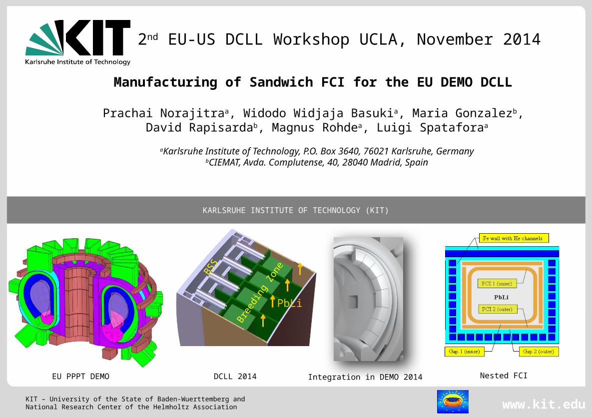
Manufacturing of Sandwich FCI for the EU DEMO DCLL
Prachai Norajitraa, Widodo Widjaja Basukia, Maria Gonzalezb, David Rapisardab, Magnus Rohdea, Luigi Spataforaa
aKarlsruhe Institute of Technology, P.O. Box 3640, 76021 Karlsruhe, GermanybCIEMAT, Avda. Complutense, 40, 28040 Madrid, Spain
EU PPPT DEMO
2nd EU-US DCLL Workshop UCLA, November 2014
DCLL 2014 Nested FCI
Bree
ding
Zon
eBSS
PbLi
Integration in DEMO 2014

2 P. Norajitra, FCI Manufacturing, 2nd EU-US DCLL WS, 2014 FUSIONKIT - EURATOM ASSOCIATION
KIT – University of the State of Baden-Wuerttemberg and National Research Center of the Helmholtz Association
1. Why do we need flow channel inserts (FCIs)?
2. Basic design principles for FCI
3. Requirements for FCI materials
4. Selected materials and their major properties
5. Several different FCI design types (pros and cons)
6. Demonstration of manufactured FCIs
7. Investigations of starting materials and post-
examination of mock-ups
8. Conclusion and outlook
Content

3 P. Norajitra, FCI Manufacturing, 2nd EU-US DCLL WS, 2014 FUSIONKIT - EURATOM ASSOCIATION
KIT – University of the State of Baden-Wuerttemberg and National Research Center of the Helmholtz Association
DCLL Blanket Concept Evolution
1994 (Ref. 1) 1997 (Ref. 2)
2003 (Ref. 3)
[1] S. Malang et al., FZKA 5581, 1995.[2] D. K. Sze et al., Fus Eng Des, 48, 371 (2000).[3] P. Norajitra et al., FZKA 6780, 2003.[4] I. Fernández, D. Rapisarda, et al., this conference.
Some common features:
• Dual coolants:
- He for cooling of structures
- PbLi as breeder and self-cooling
medium
• Poloidal PbLi flow ┴ magnetic field
LT 425 °C HT ≥700 °C - SiCf/SiC
HT 700 °C - SiCf/SiC
ARIES-ST
EU PPCS
EU DEMO
LT ~450 °C
EU PPPT
2014 (Ref. 4)

4 P. Norajitra, FCI Manufacturing, 2nd EU-US DCLL WS, 2014 FUSIONKIT - EURATOM ASSOCIATION
KIT – University of the State of Baden-Wuerttemberg and National Research Center of the Helmholtz Association
Fundamental Problem with LM Flow Through the Magnetic field
MHD pressure loss !
Remedy by the use of FCI(e.g. of sandwich type)
S. Malang et al, FZKA 5581 (1995)

5 P. Norajitra, FCI Manufacturing, 2nd EU-US DCLL WS, 2014 FUSIONKIT - EURATOM ASSOCIATION
KIT – University of the State of Baden-Wuerttemberg and National Research Center of the Helmholtz Association
Considerations about Sandwich FCI Design
1:4 scale
[P. Norajitra et al, EU PPCS-C,
FZKA 6780, 2003]
Nested FCI [S. Malang et al, FS&T, 60, 249 (2011)]
Thermal insul.Electrical insul.
6 P. Norajitra, FCI Manufacturing, 2nd EU-US DCLL WS, 2014 FUSIONKIT - EURATOM ASSOCIATION
KIT – University of the State of Baden-Wuerttemberg and National Research Center of the Helmholtz Association
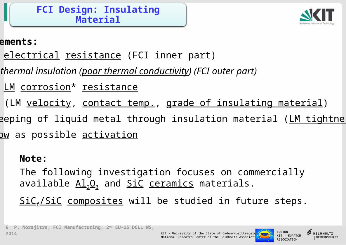
FCI Design: Insulating Material
Requirements: High electrical resistance (FCI inner part)
Good thermal insulation (poor thermal conductivity) (FCI outer part)
High LM corrosion* resistance
* f (LM velocity, contact temp., grade of insulating material)
No seeping of liquid metal through insulation material (LM tightness)
As low as possible activation
Note:
The following investigation focuses on commercially available Al2O3 and SiC ceramics materials.
SiCf/SiC composites will be studied in future steps.
7 P. Norajitra, FCI Manufacturing, 2nd EU-US DCLL WS, 2014 FUSIONKIT - EURATOM ASSOCIATION
KIT – University of the State of Baden-Wuerttemberg and National Research Center of the Helmholtz Association
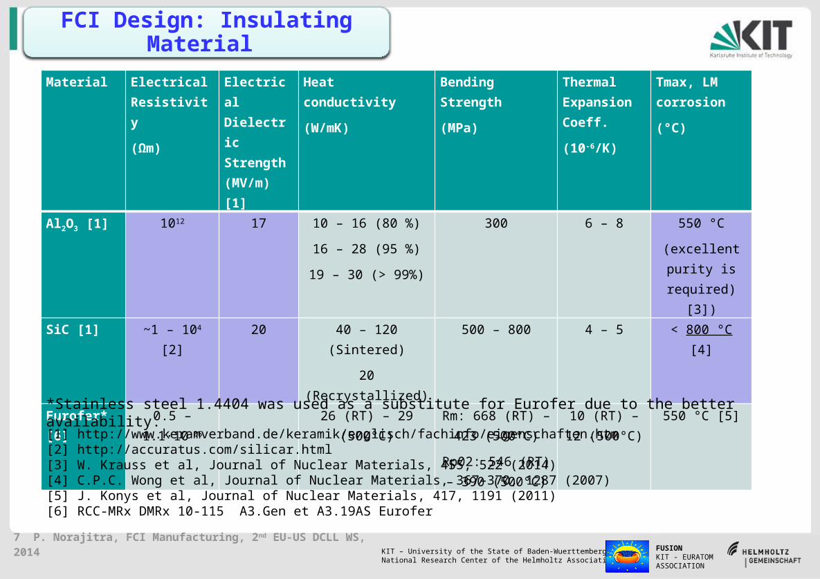
FCI Design: Insulating Material
Material Electrical Resistivity
(Ωm)
Electrical Dielectric Strength (MV/m) [1]
Heat conductivity
(W/mK)
Bending Strength
(MPa)
Thermal Expansion Coeff.
(10-6/K)
Tmax, LM corrosion
(°C)
Al2O3 [1] 1012 17 10 – 16 (80 %)
16 – 28 (95 %)
19 – 30 (> 99%)
300 6 – 8 550 °C
(excellent purity is required) [3])
SiC [1] ~1 – 104 [2] 20 40 – 120 (Sintered)
20 (Recrystallized)
500 – 800 4 – 5 < 800 °C [4]
Eurofer* [6] 0.5 – 1.1·10-06 26 (RT) – 29 (500°C) Rm: 668 (RT) – 423 (500°C)
Rp02: 546 (RT) – 390 (500°C)
10 (RT) – 12 (500°C)
550 °C [5]
[1] http://www.keramverband.de/keramik/englisch/fachinfo/eigenschaften.htm[2] http://accuratus.com/silicar.html[3] W. Krauss et al, Journal of Nuclear Materials, 455, 522 (2014)[4] C.P.C. Wong et al, Journal of Nuclear Materials, 367–370, 1287 (2007)[5] J. Konys et al, Journal of Nuclear Materials, 417, 1191 (2011)[6] RCC-MRx DMRx 10-115 A3.Gen et A3.19AS Eurofer
*Stainless steel 1.4404 was used as a substitute for Eurofer due to the better availability.

8 P. Norajitra, FCI Manufacturing, 2nd EU-US DCLL WS, 2014 FUSIONKIT - EURATOM ASSOCIATION
KIT – University of the State of Baden-Wuerttemberg and National Research Center of the Helmholtz Association
Al2O3 (or SiC) Ceramic Inter-Layer
s ~ 0.1-0.3 mm
Bent-Tube Design
Dimensions: W = 80 mm, H = 50 mm, L = 250 mm, s ~1-1,5 mm
W
HL
Tube-in-Tube Design
s
steel
steel
steel
steel
Two Bent-Tube Design
9 P. Norajitra, FCI Manufacturing, 2nd EU-US DCLL WS, 2014 FUSIONKIT - EURATOM ASSOCIATION
KIT – University of the State of Baden-Wuerttemberg and National Research Center of the Helmholtz Association
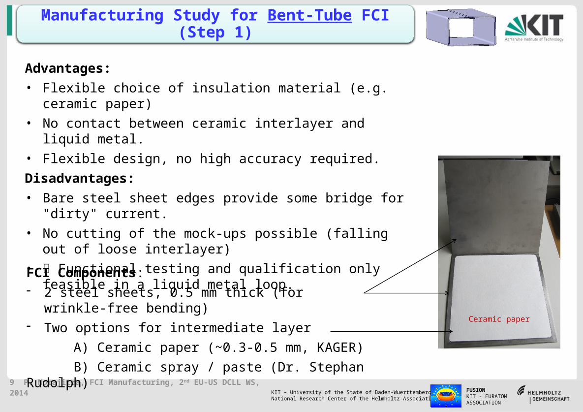
FCI Components: - 2 steel sheets, 0.5 mm thick (for wrinkle-free bending)- Two options for intermediate layer
A) Ceramic paper (~0.3-0.5 mm, KAGER)
B) Ceramic spray / paste (Dr. Stephan Rudolph)
Ceramic paper
Manufacturing Study for Bent-Tube FCI (Step 1)
Advantages:
• Flexible choice of insulation material (e.g. ceramic paper)
• No contact between ceramic interlayer and liquid metal.
• Flexible design, no high accuracy required.
Disadvantages:
• Bare steel sheet edges provide some bridge for "dirty" current.
• No cutting of the mock-ups possible (falling out of loose interlayer)
• Functional testing and qualification only feasible in a liquid metal loop.
10 P. Norajitra, FCI Manufacturing, 2nd EU-US DCLL WS, 2014 FUSIONKIT - EURATOM ASSOCIATION
KIT – University of the State of Baden-Wuerttemberg and National Research Center of the Helmholtz Association
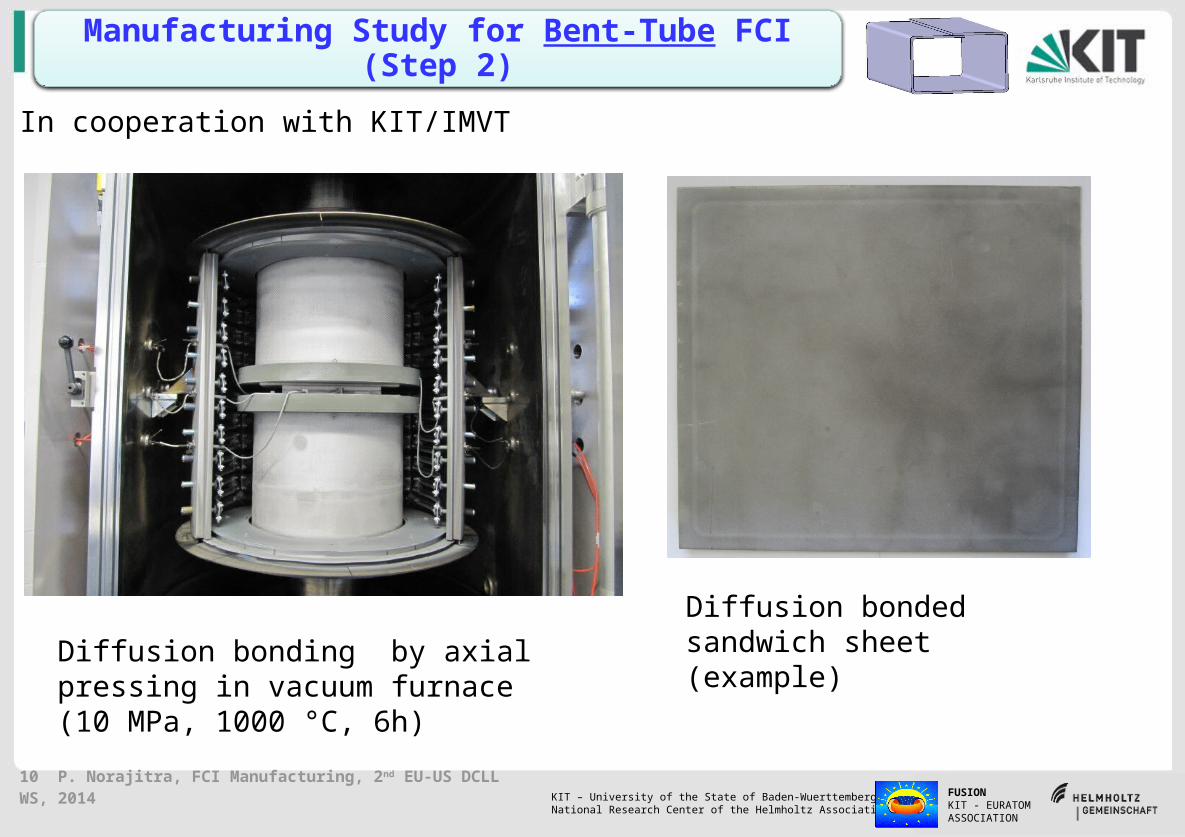
Diffusion bonding by axial pressing in vacuum furnace (10 MPa, 1000 °C, 6h)
Diffusion bonded sandwich sheet (example)
Manufacturing Study for Bent-Tube FCI (Step 2)
In cooperation with KIT/IMVT

11 P. Norajitra, FCI Manufacturing, 2nd EU-US DCLL WS, 2014 FUSIONKIT - EURATOM ASSOCIATION
KIT – University of the State of Baden-Wuerttemberg and National Research Center of the Helmholtz Association
Aluminium bending core
(A) with Cer paper (B) with Ceramic spray
Manufacturing Study for Bent-Tube FCI (Step 3)
Sandwich FCIs bent after diffusion bonding step
12 P. Norajitra, FCI Manufacturing, 2nd EU-US DCLL WS, 2014 FUSIONKIT - EURATOM ASSOCIATION
KIT – University of the State of Baden-Wuerttemberg and National Research Center of the Helmholtz Association
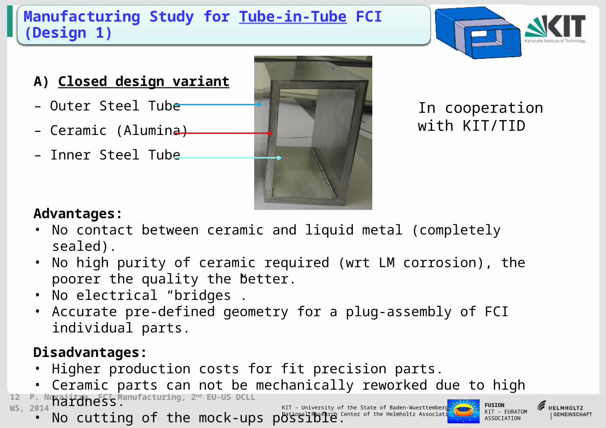
Manufacturing Study for Tube-in-Tube FCI (Design 1)
A) Closed design variant
– Outer Steel Tube
– Ceramic (Alumina)
– Inner Steel Tube
Advantages:• No contact between ceramic and liquid metal (completely sealed).• No high purity of ceramic required (wrt LM corrosion), the poorer the quality the better.• No electrical “bridges”.• Accurate pre-defined geometry for a plug-assembly of FCI individual parts.
Disadvantages:• Higher production costs for fit precision parts.• Ceramic parts can not be mechanically reworked due to high hardness.• No cutting of the mock-ups possible.• Functional testing and qualification only feasible in a liquid metal loop.• Applicability of this design version is dictated by Eurofer/PbLi corrosion at ~ 550 °C.
In cooperation with KIT/TID
13 P. Norajitra, FCI Manufacturing, 2nd EU-US DCLL WS, 2014 FUSIONKIT - EURATOM ASSOCIATION
KIT – University of the State of Baden-Wuerttemberg and National Research Center of the Helmholtz Association
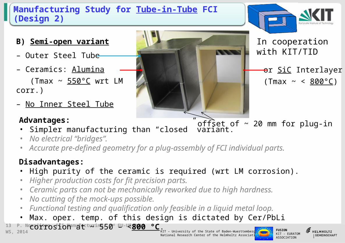
Manufacturing Study for Tube-in-Tube FCI (Design 2)
B) Semi-open variant
– Outer Steel Tube
– Ceramics: Alumina
(Tmax ~ 550°C wrt LM corr.)
– No Inner Steel Tube
or SiC Interlayer
(Tmax ~ < 800°C)
Advantages:• Simpler manufacturing than “closed” variant.• No electrical “bridges”.• Accurate pre-defined geometry for a plug-assembly of FCI individual parts.
Disadvantages:• High purity of the ceramic is required (wrt LM corrosion). • Higher production costs for fit precision parts.• Ceramic parts can not be mechanically reworked due to high hardness.• No cutting of the mock-ups possible.• Functional testing and qualification only feasible in a liquid metal loop.• Max. oper. temp. of this design is dictated by Cer/PbLi corrosion at ~ 550 – <800 °C.
offset of ~ 20 mm for plug-in
In cooperation with KIT/TID

14 P. Norajitra, FCI Manufacturing, 2nd EU-US DCLL WS, 2014 FUSIONKIT - EURATOM ASSOCIATION
KIT – University of the State of Baden-Wuerttemberg and National Research Center of the Helmholtz Association
Thermal Diffusivity of Starting Materials In cooperation with KIT/IAM-AWP
1: Cut sample from bent-tube FCI with cer spray (CS) 2: Steel – SiC adhesives – Steel 3: Steel – Al2O3 adhesives – Steel 4: Steel –ceramic paper (CP) – Steel, glued with Al2O3
adhesives
0 100 200 300 400 5000,000
0,005
0,010
0,015
0,020
0,025
0,030
The
rmal
diff
usiv
ity, c
m2 /s
Temperature, °C
FCI-Sandwich
1.4404 mit SiC-Kleber
1.4404 mit Al2O
3-Kleber
1.4404 mit Al2O
3-Kleber+ Keramikpapier
1
2
3
4
(2nd MSR @ RT)
(2nd MSR @ RT)
IR detector
Iris diaphragmGe lens
CaF2 IR window
Specimen holder
Cooling water
Graphite heater
Support tube
Quick closure
Specimens adjustment
Divergent optics
Adjusting laser
Quartz glass window
Output coupler mirror
Shoulder
Resonator
Rearview mirror
Laser flash thermal measurement device
SiC
Al2O3
CP
B-T FCICS

15 P. Norajitra, FCI Manufacturing, 2nd EU-US DCLL WS, 2014 FUSIONKIT - EURATOM ASSOCIATION
KIT – University of the State of Baden-Wuerttemberg and National Research Center of the Helmholtz Association
Post-Examination of Produced Bent-Tube Mock-Ups (with Ceramic Spray)
- No wrinkles formation observed.- Despite strong bending at corners, no contact between
the steel sheets, i.e. no short circuit.- No constant insulation thickness.
Ceramic layer
Ceramic layer
steel sheet
steel sheet
Steel sheet
Optical Micrograph
In cooperation with KIT/IAM-WBM

16 P. Norajitra, FCI Manufacturing, 2nd EU-US DCLL WS, 2014 FUSIONKIT - EURATOM ASSOCIATION
KIT – University of the State of Baden-Wuerttemberg and National Research Center of the Helmholtz Association
Preliminary Resistivity Data for Produced Tube-in-Tube FCI Mock-Ups
• Surface resistivity was calculated from the resistance measurement between two electrodes on the surface of the insulating material, taken into account electrode dimensions.
• Measurements were performed on the tube-in-tube, semi-open mock-ups with alumina and SiC insulator (Table).
Overall results: Good agreement with literature reported data.
High dispersion in resistivity values indicates the presence of defects, impurities, low grade or poor homogeneity of dopant in ceramic insulator.
Al2O3 SiC
mean resistivity (ohm.m) 4 ±2 x 10¹¹ 0.1 – 102
Testing on small sample recommended
In cooperation with CIEMAT
Al2O3 SiC
17 P. Norajitra, FCI Manufacturing, 2nd EU-US DCLL WS, 2014 FUSIONKIT - EURATOM ASSOCIATION
KIT – University of the State of Baden-Wuerttemberg and National Research Center of the Helmholtz Association
Conclusions
• Requirements for the ceramic material for use in FCI design were summarized, material data for selected Al2O3 and SiC presented.
• Two design variations Bent-Tube and Tube-in-Tube were presented.
• The latter with subdivision in Closed- and Semi-open designs.
• Their advantages and disadvantages were discussed.
• Manufacturing studies conducted with 1:4 scale mock-ups have confirmed the feasibility and manufacturability for all design variants.
• Measurement of starting material properties and post-examination of produced mock-ups show good agreement with literature.
Open issues for future R & D are:
• Transferability to a 1:1 full scale mock-up has to be checked.
• Study on 3D printing technology.
• Function tests and characterization of FCIs under real magnetic conditions in a PbLi loop.
• Manufacturing study for an advanced FCI with SiCf/SiC composite material.
• Influence of n-irradiation on the properties of ceramic material, in particualr radiation-induced electrical degradation (RIED).

18 P. Norajitra, FCI Manufacturing, 2nd EU-US DCLL WS, 2014 FUSIONKIT - EURATOM ASSOCIATION
KIT – University of the State of Baden-Wuerttemberg and National Research Center of the Helmholtz Association
Thank you for your attention!