kit33883frdmevm evaluation board - nxp semiconductors · 2017-05-22 · mc33883 h-bridge gate...
TRANSCRIPT

KIT33883FRDMEVMUGKIT33883FRDMEVM evaluation boardRev. 1.0 — 9 May 2017 User guide
1 KIT33883FRDM-EVM evaluation board
Figure 1. KIT33883FRDM-EVM with FRDM-KL25Z Freedom Development Platform

NXP Semiconductors KIT33883FRDMEVMUGKIT33883FRDMEVM evaluation board
KIT33883FRDMEVMUG All information provided in this document is subject to legal disclaimers. © NXP B.V. 2017. All rights reserved.
User guide Rev. 1.0 — 9 May 20172 / 24
2 Important notice
NXP provides the enclosed product(s) under the following conditions:
This evaluation kit is intended for use of ENGINEERING DEVELOPMENT OREVALUATION PURPOSES ONLY. It is provided as a sample IC pre-soldered to aprinted circuit board to make it easier to access inputs, outputs, and supply terminals.This evaluation board may be used with any development system or other source ofI/O signals by simply connecting it to the host MCU or computer board via off-the-shelf cables. This evaluation board is not a Reference Design and is not intended torepresent a final design recommendation for any particular application. Final device inan application will be heavily dependent on proper printed circuit board layout and heatsinking design as well as attention to supply filtering, transient suppression, and I/Osignal quality.
The goods provided may not be complete in terms of required design, marketing, andor manufacturing related protective considerations, including product safety measurestypically found in the end product incorporating the goods. Due to the open constructionof the product, it is the user's responsibility to take any and all appropriate precautionswith regard to electrostatic discharge. In order to minimize risks associated with thecustomers applications, adequate design and operating safeguards must be providedby the customer to minimize inherent or procedural hazards. For any safety concerns,contact NXP sales and technical support services.
Should this evaluation kit not meet the specifications indicated in the kit, it may bereturned within 30 days from the date of delivery and will be replaced by a new kit.
NXP reserves the right to make changes without further notice to any products herein.NXP makes no warranty, representation or guarantee regarding the suitability of itsproducts for any particular purpose, nor does NXP assume any liability arising out of theapplication or use of any product or circuit, and specifically disclaims any and all liability,including without limitation consequential or incidental damages. “Typical” parameterscan and do vary in different applications and actual performance may vary over time.All operating parameters, including “Typical”, must be validated for each customerapplication by customer’s technical experts.
NXP does not convey any license under its patent rights nor the rights of others. NXPproducts are not designed, intended, or authorized for use as components in systemsintended for surgical implant into the body, or other applications intended to support orsustain life, or for any other application in which the failure of the NXP product couldcreate a situation where personal injury or death may occur.
Should the Buyer purchase or use NXP products for any such unintended orunauthorized application, the Buyer shall indemnify and hold NXP and its officers,employees, subsidiaries, affiliates, and distributors harmless against all claims, costs,damages, and expenses, and reasonable attorney fees arising out of, directly orindirectly, any claim of personal injury or death associated with such unintended orunauthorized use, even if such claim alleges NXP was negligent regarding the design ormanufacture of the part.
NXP and the NXP logo are trademarks of NXP B.V. All other product or service namesare the property of their respective owners. © NXP B.V. 2017.
NXP Semiconductors KIT33883FRDMEVMUGKIT33883FRDMEVM evaluation board
KIT33883FRDMEVMUG All information provided in this document is subject to legal disclaimers. © NXP B.V. 2017. All rights reserved.
User guide Rev. 1.0 — 9 May 20173 / 24
3 Getting started
3.1 Kit contents and packing listThe KIT33883FRDM-EVM contents include:
• Assembled and tested evaluation board/module with MC33883 in an antistatic bag• FRDM-KL25Z board• Warranty card
3.2 Jump startThe analog product development boards from NXP help the evaluation of NXP products.These tools support analog mixed signal and power solutions, including monolithic ICsusing proven high-volume SMARTMOS mixed signal technology, and system-in-packagedevices utilizing power, SMARTMOS and MCU dies. NXP products enable longer batterylife, smaller form factor, component count reduction, ease of design, lower system costand improved performance in powering state-of-the-art systems.
• Go to the tool summary page: www.nxp.com/KIT33883FRDMEVM• Locate your kit• Review your tool summary page• Look for
• Download documents, software and other information
Once the files are downloaded, review the user guide in the bundle. The user guideincludes setup instructions, BOM and schematics. Jump start bundles are available oneach tool summary page with the most relevant and current information. The informationincludes everything needed for design.
3.3 Required equipmentTo use this kit, you need:
• DC Power supply (5.5 V to 55 V, up to 20 A current handling capability, depending onmotor requirements)
• USB Mini-B to Standard A cable• Typical loads (brushed DC motor, power resistors or inductive load)• Function generator (required if FRDM-KL25Z not used)• FRDM-KL25Z Freedom Development Platform (included in KIT)• 3/16" blade screwdriver
3.4 System requirementsTo use this kit, you need:
• USB-enabled PC with Windows® XP or higher

NXP Semiconductors KIT33883FRDMEVMUGKIT33883FRDMEVM evaluation board
KIT33883FRDMEVMUG All information provided in this document is subject to legal disclaimers. © NXP B.V. 2017. All rights reserved.
User guide Rev. 1.0 — 9 May 20174 / 24
4 Getting to know the hardware
4.1 Board overviewThe KIT33883FRDM-EVM Evaluation Board (EVB) is an easy-to-use circuit board thatallows the user to exercise all the functions of the MC33883 H-Bridge device. The EVBparallel input can be easily controlled through lab equipment, any MCU with GPIOs orFRDM-KL25Z board connected to a PC’s USB port.
4.2 Board featuresThe KIT33883FRDM-EVM evaluation board is able to easily evaluate and test the maincomponent, the MC33883. The main features of the board are as follows:
• Compatible with Freedom Development Platform Accessory Boards• Built-in reverse battery protection• Screw terminals to provide easy connection of power and loads• Test points to allow probing of signals• LEDs to indicate status of the supply• Low ESR capacitor to reduce ripple in the power supply
4.3 Block diagramThe hardware basic block diagram of KIT33883FRDM-EVM is shown in Figure 2.
VBAT1
VBAT1
VBAT2
D
S
G
D
S
G
D
S
G
D
S
G
IN_LS1
IN_HS1
CP_OUTVCC
VIN LED
VBAT1LED
VBAT2LED
Powersupply
FRDMKL25Z/MCU
Load
Reversebattery
protection
Externalconnections
FRDM-KL25Z/MCUGPIO
VIN
Screw terminals
Screw terminals
Screw terminals
aaa-026962
Charge pump capacitor
VCC2
IN_LS2
IN_HS2
GATE_HS1
GATE_LS1
GATE_HS2
GATE_LS2
G_EN
VBAT1
MC33883
GND
GND
GND
OUT1
OUT2
All grounds
Figure 2. Block diagram
NXP Semiconductors KIT33883FRDMEVMUGKIT33883FRDMEVM evaluation board
KIT33883FRDMEVMUG All information provided in this document is subject to legal disclaimers. © NXP B.V. 2017. All rights reserved.
User guide Rev. 1.0 — 9 May 20175 / 24
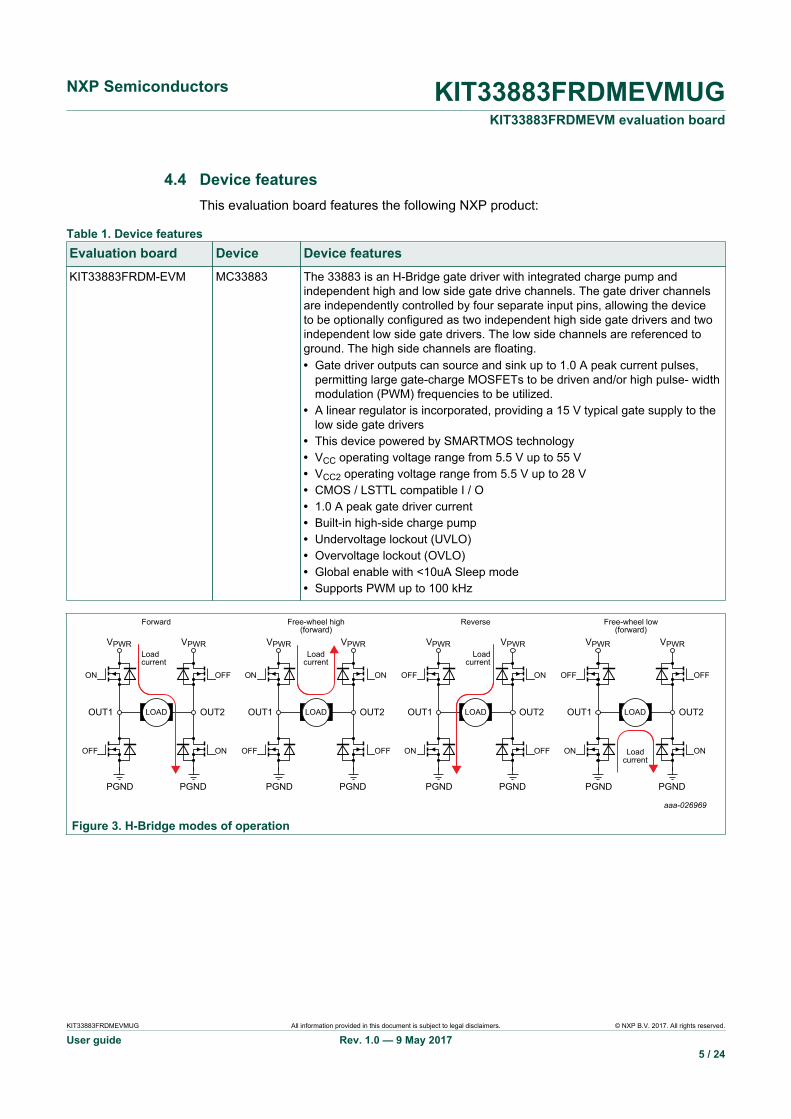
4.4 Device featuresThis evaluation board features the following NXP product:
Table 1. Device featuresEvaluation board Device Device featuresKIT33883FRDM-EVM MC33883 The 33883 is an H-Bridge gate driver with integrated charge pump and
independent high and low side gate drive channels. The gate driver channelsare independently controlled by four separate input pins, allowing the deviceto be optionally configured as two independent high side gate drivers and twoindependent low side gate drivers. The low side channels are referenced toground. The high side channels are floating.• Gate driver outputs can source and sink up to 1.0 A peak current pulses,
permitting large gate-charge MOSFETs to be driven and/or high pulse- widthmodulation (PWM) frequencies to be utilized.
• A linear regulator is incorporated, providing a 15 V typical gate supply to thelow side gate drivers
• This device powered by SMARTMOS technology• VCC operating voltage range from 5.5 V up to 55 V• VCC2 operating voltage range from 5.5 V up to 28 V• CMOS / LSTTL compatible I / O• 1.0 A peak gate driver current• Built-in high-side charge pump• Undervoltage lockout (UVLO)• Overvoltage lockout (OVLO)• Global enable with <10uA Sleep mode• Supports PWM up to 100 kHz
VPWR VPWRLoadcurrent
ON
ON
OUT1
OFF
OFF
PGND PGND
OUT2
VPWR VPWRLoad
currentON ON
OUT1
OFF OFF
PGND PGND
OUT2
VPWR VPWRLoad
current
ON
ON
OUT1
OFF
OFF
PGND PGND
OUT2
VPWR VPWR
Loadcurrent
ON ON
OUT1
OFF OFF
PGND
aaa-026969
PGND
OUT2LOAD
Forward
LOAD
Free-wheel high(forward)
LOAD
Reverse
LOAD
Free-wheel low(forward)
Figure 3. H-Bridge modes of operation

NXP Semiconductors KIT33883FRDMEVMUGKIT33883FRDMEVM evaluation board
KIT33883FRDMEVMUG All information provided in this document is subject to legal disclaimers. © NXP B.V. 2017. All rights reserved.
User guide Rev. 1.0 — 9 May 20176 / 24
aaa-026967
Figure 4. Architecture MC33883

NXP Semiconductors KIT33883FRDMEVMUGKIT33883FRDMEVM evaluation board
KIT33883FRDMEVMUG All information provided in this document is subject to legal disclaimers. © NXP B.V. 2017. All rights reserved.
User guide Rev. 1.0 — 9 May 20177 / 24
4.5 Board descriptionFigure 5 describes the main components of the KIT33883FRDM-EVM.
Table 2. Board descriptionName DescriptionMC33883 H-Bridge gate driver IC in a robust 20 pin SOIC package
Jumpers Jumpers for configuring the board for different modes of operation
Reverse battery protection MOSFET for protecting MC33883 in reverse battery condition
Power and ground inputs Power supply terminal to connect the battery/power supplies with the board
Test points Test points to probe different signals
FRDM-KL25Z module NXP Freedom development platform
Output terminal Output connecter to connect a load to the MC33883 controlled output
Figure 5. Board description
4.6 LED displayThe following table describes LEDs provided as visual output devices for theKIT33883EVM evaluation board:
NXP Semiconductors KIT33883FRDMEVMUGKIT33883FRDMEVM evaluation board
KIT33883FRDMEVMUG All information provided in this document is subject to legal disclaimers. © NXP B.V. 2017. All rights reserved.
User guide Rev. 1.0 — 9 May 20178 / 24
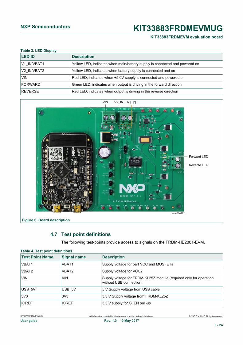
Table 3. LED DisplayLED ID DescriptionV1_IN/VBAT1 Yellow LED, indicates when main/battery supply is connected and powered on
V2_IN/VBAT2 Yellow LED, indicates when battery supply is connected and on
VIN Red LED, indicates when +5.0V supply is connected and powered on
FORWARD Green LED, indicates when output is driving in the forward direction
REVERSE Red LED, indicates when output is driving in the reverse direction
Figure 6. Board description
4.7 Test point definitionsThe following test-points provide access to signals on the FRDM-HB2001-EVM.
Table 4. Test point definitionsTest Point Name Signal name DescriptionVBAT1 VBAT1 Supply voltage for part VCC and MOSFETs
VBAT2 VBAT2 Supply voltage for VCC2
VIN VIN Supply voltage for FRDM-KL25Z module (required only for operationwithout USB connection
USB_5V USB_5V 5 V Supply voltage from USB cable
3V3 3V3 3.3 V Supply voltage from FRDM-KL25Z
IOREF IOREF 3.3 V supply for G_EN pull-up

NXP Semiconductors KIT33883FRDMEVMUGKIT33883FRDMEVM evaluation board
KIT33883FRDMEVMUG All information provided in this document is subject to legal disclaimers. © NXP B.V. 2017. All rights reserved.
User guide Rev. 1.0 — 9 May 20179 / 24
Test Point Name Signal name DescriptionCFB CFB Current sense output for real time load current monitoring
G_EN G_EN Logic input Enable control of device
IN_HS1 IN_HS1 Logic input control of high-side 1 gate
IN_LS1 IN_LS1 Logic input control of low-side 1 gate
IN_HS2 IN_HS2 Logic input control of high-side 2 gate
IN_LS2 IN_LS2 Logic input control of low-side 2 gate
OUT1 OUT1 Output 1 of H-Bridge
OUT2 OUT2 Output 2 of H-Bridge
GND1 GND Ground signal
GND2 GND Ground signal
GND3 GND Ground signal
4.8 Input signal definitionsThe KIT33883FRDM-EVM board has following input signals which are used to control theoutputs or functions inside the circuit.
Table 5. Input signal definitionsInput name DescriptionIN_HS1 Logic input control of high-side 1 gate, such as IN_HS1 logic HIGH =
GATE_HS1 HIGH)
IN_LS1 Logic input control of low-side 1 gate, such as IN_LS1 logic HIGH =GATE_LS1 HIGH)
IN_LS2 Logic input control of low-side 2 gate, such as IN_LS2 logic HIGH =GATE_LS2 HIGH)
IN_HS2 Logic input control of high-side 2 gate, such as IN_HS2 logic HIGH =GATE_HS2 HIGH)
G_EN Logic input Enable control of device, such as G_EN logic HIGH = FullOperation, G_EN logic LOW = Sleep Mode)
4.9 Output signal definitionsThe KIT33883FRDM-EVM board has the following output signals that are used to drivea load, such as a brushed DC motor. The board provides an analog output for real-timeload-current monitoring. This signal allows closed-loop control of the load.
Table 6. Output signal definitionsOutput name DescriptionOUT1 Output 1 of H-Bridge
OUT2 Output 2 of H-Bridge
CFB Current sense output for real-time load-current monitoring
NXP Semiconductors KIT33883FRDMEVMUGKIT33883FRDMEVM evaluation board
KIT33883FRDMEVMUG All information provided in this document is subject to legal disclaimers. © NXP B.V. 2017. All rights reserved.
User guide Rev. 1.0 — 9 May 201710 / 24
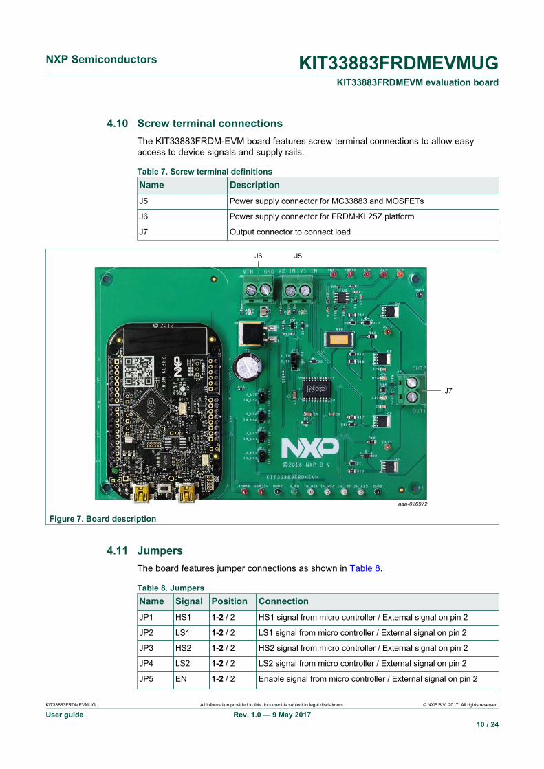
4.10 Screw terminal connectionsThe KIT33883FRDM-EVM board features screw terminal connections to allow easyaccess to device signals and supply rails.
Table 7. Screw terminal definitionsName DescriptionJ5 Power supply connector for MC33883 and MOSFETs
J6 Power supply connector for FRDM-KL25Z platform
J7 Output connector to connect load
Figure 7. Board description
4.11 JumpersThe board features jumper connections as shown in Table 8.
Table 8. JumpersName Signal Position ConnectionJP1 HS1 1-2 / 2 HS1 signal from micro controller / External signal on pin 2
JP2 LS1 1-2 / 2 LS1 signal from micro controller / External signal on pin 2
JP3 HS2 1-2 / 2 HS2 signal from micro controller / External signal on pin 2
JP4 LS2 1-2 / 2 LS2 signal from micro controller / External signal on pin 2
JP5 EN 1-2 / 2 Enable signal from micro controller / External signal on pin 2
NXP Semiconductors KIT33883FRDMEVMUGKIT33883FRDMEVM evaluation board
KIT33883FRDMEVMUG All information provided in this document is subject to legal disclaimers. © NXP B.V. 2017. All rights reserved.
User guide Rev. 1.0 — 9 May 201711 / 24
KIT33883FRDM-EVM gives the user freedom to operate the part using the FRDM-KL25Zboard with GUI, any MCU with GPIO and ADC and simple lab equipment. A GUI and anMCU program, which works with the FRDM-KL25Z (shipped with the EVM), are availableonline at the evaluation board tool summary page at www.nxp.com/KIT33883FRDMEVM.
Moreover, KIT33883FRDM-EVM is compatible with any Arduino platform board.Nonetheless, the user will need to write MCU code to make it work with any board otherthan the FRDM-KL25Z.
5 FRDM-KL25Z Freedom Development Platform
The NXP Freedom development platform is a set of software and hardware tools forevaluation and development. It is ideal for rapid prototyping of microcontroller-basedapplications. The NXP Freedom KL25Z hardware, FRDM-KL25Z, is a simple, yetsophisticated design featuring a Kinetis L Series microcontroller, the industry's firstmicrocontroller built on the ARM® Cortex™-M0+ core.
5.1 Connecting a FRDM-KL25Z to the boardThe KIT33883FRDM-EVM kit may be used with many of the Freedom platformevaluation boards featuring Kinetis processors. The FRDM-KL25Z evaluation board hasbeen chosen specifically to work with the KIT33883FRDM-EVM kit because of its lowcost and features. The FRDM-KL25Z board makes use of the USB, built in LEDs, and I/O ports available with NXP’s Kinetis KL2x family of microcontrollers. The main functionsprovided by the FRDM-KL25Z are to allow control of a DC brushed motor using a PCcomputer over USB, and to drive the necessary inputs on the KIT33883FRDM-EVMevaluation kit to operate the motor via GPIOs.
The KIT33883FRDM-EVM is connected to the FRDM-KL25Z using four single rowheaders. The connections are as follows in Table 9

NXP Semiconductors KIT33883FRDMEVMUGKIT33883FRDMEVM evaluation board
KIT33883FRDMEVMUG All information provided in this document is subject to legal disclaimers. © NXP B.V. 2017. All rights reserved.
User guide Rev. 1.0 — 9 May 201712 / 24
Table 9. KIT33883FRDM-EVM to FRDM-KL25Z connectionsKIT33883FRDM-EVM FRDM-KL25Z
Header Pin Name Description Header Pin Name
JA1 1 N/C No connection J1 — —
JA1 2 N/C No connection J1 — —
JA1 3 N/C No connection J1 — —
JA1 4 U_HS1 IN_HS1 signal from MCU J1 8 PTA12
JA1 5 N/C No connection J1 — —
JA1 6 U_LS1 IN_LS1 signal from MCU J1 12 PTA5
JA1 7 U_HS2 IN_HS2 signal from MCU J1 14 PTC8
JA1 8 N/C No connection J1 — —
JA2 1 N/C No connection J2 — —
JA2 2 U_LS2 IN_LS2 signal from MCU J2 4 PTD5
JA2 3 N/C No connection J2 — —
JA2 4 N/C No connection J2 — —
JA2 5 N/C No connection J2 — —
JA2 6 N/C No connection J2 — —
JA2 7 GND Ground connection J2 14 GND
JA2 8 N/C No connection J2 — —
JA2 9 N/C No connection J2 — —
JA2 10 N/C No connection J2 — —
JA3 1 N/C No connection J9 — —
JA3 2 IOREF 3.3V supply for G_EN pull-up J9 4 P3V3
JA3 3 N/C No connection J9 — —
JA3 4 3V3 3.3V output from FRDM-KL25Z J9 8 P3V3
JA3 5 USB_5V 5V supply from USB connection J9 10 P5V_USB
JA3 6 GND Ground connection J9 12 GND
JA3 7 GND Ground connection J9 — —
JA3 8 VIN VIN supply signal J9 16 P5-9V_VIN
JA4 1 U_CFB Current feedback from current sense circuit J10 2 PTB0
JA4 2 N/C No connection J10 — —
JA4 3 N/C No connection J10 — —
JA4 4 U_EN Enable signal from MCU J10 8 PTB3
JA4 5 N/C No connection J10 — —
JA4 6 N/C No connection J10 — —

NXP Semiconductors KIT33883FRDMEVMUGKIT33883FRDMEVM evaluation board
KIT33883FRDMEVMUG All information provided in this document is subject to legal disclaimers. © NXP B.V. 2017. All rights reserved.
User guide Rev. 1.0 — 9 May 201713 / 24
Figure 8. Board description
6 Setting up the hardware and software
To configure the evaluation board for use with the FRDM KL25Z and the Graphical UserInterface (GUI) you must:
• Connect the hardware• Download the mbed firmware to the FRDM-KL25Z board• Download the MC33883 microcode to the FRDM-KL25Z board• Install the Graphical User Interface MC33883 Evaluation Board GUI for
KIT33883FRDM-EVM.
6.1 Installing the Motor Control GUI on your computerThe Graphical User Interface (GUI) provides a PC-based interface allowing you to easilyexercise KIT33883FRDM-EVM functions to control a DC Brushed Motor. The GUI runson any Windows 7 or greater operating system.
To install the software:
1. Go to the evaluation board tool summary page at www.nxp.com/KIT33883FRDMEVM.2. Under Jump Start Your Design, click on the Get Started with the KIT33883FRDM-
EVM link.3. From the list of files that appear, click on the link for the MC33883 GUI software.
NXP Semiconductors KIT33883FRDMEVMUGKIT33883FRDMEVM evaluation board
KIT33883FRDMEVMUG All information provided in this document is subject to legal disclaimers. © NXP B.V. 2017. All rights reserved.
User guide Rev. 1.0 — 9 May 201714 / 24
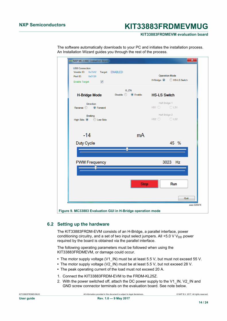
The software automatically downloads to your PC and initiates the installation process.An Installation Wizard guides you through the rest of the process.
aaa-026976
Figure 9. MC33883 Evaluation GUI in H-Bridge operation mode
6.2 Setting up the hardwareThe KIT33883FRDM-EVM consists of an H-Bridge, a parallel interface, powerconditioning circuitry, and a set of two input select jumpers. All +5.0 V VDD powerrequired by the board is obtained via the parallel interface.
The following operating parameters must be followed when using theKIT33883FRDMEVM, or damage could occur.
• The motor supply voltage (V1_IN) must be at least 5.5 V, but must not exceed 55 V.• The motor supply voltage (V2_IN) must be at least 5.5 V, but not exceed 28 V.• The peak operating current of the load must not exceed 20 A.
1. Connect the KIT33883FRDM-EVM to the FRDM-KL25Z.2. With the power switched off, attach the DC power supply to the V1_IN, V2_IN and
GND screw connector terminals on the evaluation board. See note below.
NXP Semiconductors KIT33883FRDMEVMUGKIT33883FRDMEVM evaluation board
KIT33883FRDMEVMUG All information provided in this document is subject to legal disclaimers. © NXP B.V. 2017. All rights reserved.
User guide Rev. 1.0 — 9 May 201715 / 24
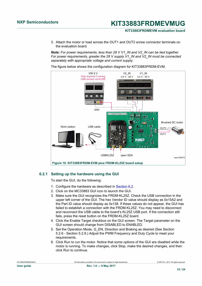
3. Attach the motor or load across the OUT1 and OUT2 screw connector terminals onthe evaluation board.
Note: For power requirements, less than 28 V V1_IN and V2_IN can be tied together.For power requirements, greater the 28 V supply V1_IN and V2_IN must be connectedseparately with appropriate voltage and current supply.
The figure below shows the configuration diagram for KIT33883FRDM-EVM.
Figure 10. KIT33883FRDM-EVM plus FRDM-KL25Z board setup
6.2.1 Setting up the hardware using the GUITo start the GUI, do the following:
1. Configure the hardware as described in Section 6.2.2. Click on the MC33883 GUI icon to launch the GUI.3. Make sure the GUI recognizes the FRDM-KL25Z. Check the USB connection in the
upper left corner of the GUI. The hex Vendor ID value should display as 0x15A2 andthe Part ID value should display as 0x138. If these values do not appear, the GUI hasfailed to establish a connection with the FRDM-KL25Z. You may need to disconnectand reconnect the USB cable to the board’s KL25Z USB port. If the connection stillfails, press the reset button on the FRDM-KL25Z board.
4. Click the Enable Target checkbox on the GUI screen. The Target parameter on theGUI screen should change from DISABLED to ENABLED.
5. Set the Operation Mode, G_EN, Direction and Braking as desired (See Section5.2.6 - Section 5.2.9.) Adjust the PWM Frequency and Duty Cycle to meet yourrequirements.
6. Click Run to run the motor. Notice that some options of the GUI are disabled while themotor is running. To make changes, click Stop, make the desired changes, and thenclick Run to continue.
NXP Semiconductors KIT33883FRDMEVMUGKIT33883FRDMEVM evaluation board
KIT33883FRDMEVMUG All information provided in this document is subject to legal disclaimers. © NXP B.V. 2017. All rights reserved.
User guide Rev. 1.0 — 9 May 201716 / 24
7. When finished, Stop, deselect the Enable Target button on the GUI, and click Quit.Turn off DC power supply and remove the USB cable.
The GUI is shown in Figure 12. The hex address numbers at the top are loaded with thevendor ID for Freescale (0x15A2), and the part ID (0x138). The left side panel displaysthese numbers only if the PC is communicating with the FRDM-KL25Z via the USBinterface.
6.3 Downloading software to the FRDM-KL25Z board
6.3.1 Downloading mbed® firmware to the FRDM-KL25Z board
You must install mbed® firmware on the FRDM-KL25Z board to enable downloading ofthe MC33883 microcode. The procedure is as follows:
1. Connect the USB cable between your PC and the OpenSDA USB port on the FRDM-KL25Z board.
2. Download the mbed firmware onto the FRDM-KL25Z board. The instructions are onthe ARM®mbed™ website at the following url: https://developer.mbed.org/handbook/Firmware-FRDM-KL25Z
3. After downloading the mbed firmware, power cycle the board (by disconnecting thenreconnecting the USB cable to the OpenSDA port) to initiate the firmware update.When this process completes, a USB drive named “mbed” should appear on your PC.
6.3.2 Downloading the MC33883 microcode to the FRDM-KL25Z boardThe MC33883 microcode provides the firmware interface between the MC33883 device,the Freedom platform and the GUI. The procedure is as follows:
1. Connect the USB cable between your PC and the OpenSDA USB port on the FRDM-KL25Z board.
2. Go to www.nxp.com/KIT33883FRDMEVM-Design_Tools_Tab and download theMC33883_KL25Z.bin file to your PC. Copy the file to the MBED drive that appears onyour PC after a USB cable is connected to the OpenSDA port. See Figure 11The source code for MC33883_KL25Z.bin is also available (main.cpp). Ifmodifications are made must be recompiled and can be done by importing intodeveloper.mbed.org, creating an account, and recompiling the project to another .binfile.
3. Remove the USB connector from the FRDM-KL25Z OpenSDA USB port andinsert it in the USBKL25Z port. The KL25Z board is now ready for use with theKIT33883FRDM-EVM and the MC33883 Motor Control GUI.

NXP Semiconductors KIT33883FRDMEVMUGKIT33883FRDMEVM evaluation board
KIT33883FRDMEVMUG All information provided in this document is subject to legal disclaimers. © NXP B.V. 2017. All rights reserved.
User guide Rev. 1.0 — 9 May 201717 / 24
Figure 11. MBED drive
NXP Semiconductors KIT33883FRDMEVMUGKIT33883FRDMEVM evaluation board
KIT33883FRDMEVMUG All information provided in this document is subject to legal disclaimers. © NXP B.V. 2017. All rights reserved.
User guide Rev. 1.0 — 9 May 201718 / 24
7 Using the GUI
7.1 H-Bridge mode description
aaa-026976
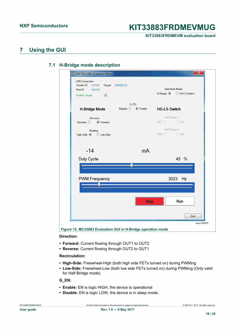
Figure 12. MC33883 Evaluation GUI in H-Bridge operation mode
Direction:
• Forward: Current flowing through OUT1 to OUT2• Reverse: Current flowing through OUT2 to OUT1
Recirculation:
• High-Side: Freewheel-High (both high side FETs turned on) during PWMing• Low-Side: Freewheel-Low (both low side FETs turned on) during PWMing (Only valid
for Half-Bridge mode)
G_EN:
• Enable: EN is logic HIGH, the device is operational• Disable: EN is logic LOW, the device is in sleep mode.

NXP Semiconductors KIT33883FRDMEVMUGKIT33883FRDMEVM evaluation board
KIT33883FRDMEVMUG All information provided in this document is subject to legal disclaimers. © NXP B.V. 2017. All rights reserved.
User guide Rev. 1.0 — 9 May 201719 / 24
PWM Frequency:
• Enter PWM frequency up to 20kHz
Duty cycle (%):
• Select PWM duty cycle from 0-100%
Run:
• After selection of parallel control configuration, press Start to activate the outputs.
Stop:
• Press Stop to deactivate the outputs.
Current feedback:
Shows current through High-Side FET using the current recopy feature.
7.2 HS-LS Switch mode description
aaa-026977
Figure 13. MC33883 Evaluation GUI in H-Bridge operation mode

NXP Semiconductors KIT33883FRDMEVMUGKIT33883FRDMEVM evaluation board
KIT33883FRDMEVMUG All information provided in this document is subject to legal disclaimers. © NXP B.V. 2017. All rights reserved.
User guide Rev. 1.0 — 9 May 201720 / 24
Control:
HS1: Current flowing through HS1 to OUT1 HS2: Current flowing through HS2 to OUT2
VBAT1
HS1 on
OUT1 LOAD
D
S
G
aaa-026978
VBAT1
HS2 on
OUT2 LOAD
D
S
G
aaa-026979
LS1: Current flowing through LS1 to OUT1 LS2: Current flowing through LS2 to OUT2
VBAT1
LS1 on
OUT1LOAD
D
S
G
aaa-026980
VBAT1
LS2 on
OUT2LOAD
D
S
G
aaa-026981
G_EN:
• Enable: EN is logic HIGH, the device is operational.• Disable: EN is logic LOW, the device is in sleep mode.
PWM Frequency:
• Enter PWM frequency up to 20kHz. Note: FCC was tested at 10 kHz.
Duty cycle (%):
• Select PWM duty cycle from 0-100%
Run:
• After selection of parallel control configuration, press Start to activate the outputs.
Stop:
• Press Stop to deactivate the outputs.
Current Feedback:
Shows current valid only on Low-Side FETs using the current recopy feature. If both Low-Side FETs are used simultaneously Current Feedback will display summation of LowSide FETs.
NXP Semiconductors KIT33883FRDMEVMUGKIT33883FRDMEVM evaluation board
KIT33883FRDMEVMUG All information provided in this document is subject to legal disclaimers. © NXP B.V. 2017. All rights reserved.
User guide Rev. 1.0 — 9 May 201721 / 24
8 Schematics, board layout and bill of materials
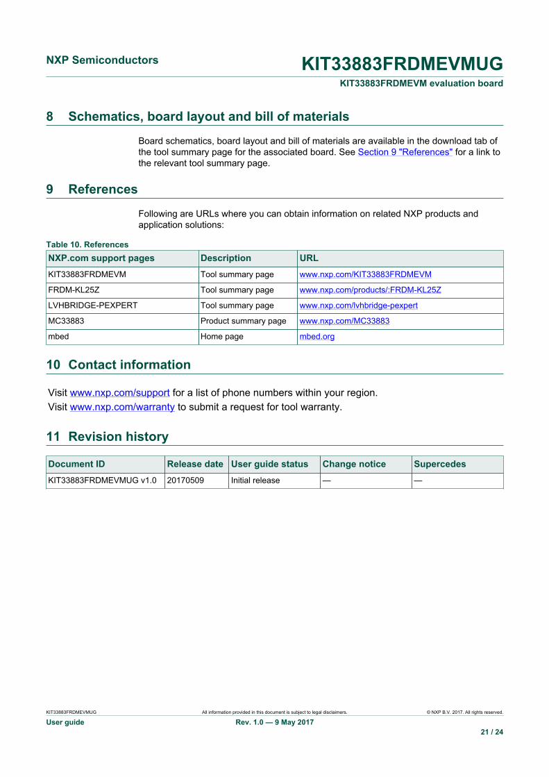
Board schematics, board layout and bill of materials are available in the download tab ofthe tool summary page for the associated board. See Section 9 "References" for a link tothe relevant tool summary page.
9 References
Following are URLs where you can obtain information on related NXP products andapplication solutions:
Table 10. ReferencesNXP.com support pages Description URLKIT33883FRDMEVM Tool summary page www.nxp.com/KIT33883FRDMEVM
FRDM-KL25Z Tool summary page www.nxp.com/products/:FRDM-KL25Z
LVHBRIDGE-PEXPERT Tool summary page www.nxp.com/lvhbridge-pexpert
MC33883 Product summary page www.nxp.com/MC33883
mbed Home page mbed.org
10 Contact information
Visit www.nxp.com/support for a list of phone numbers within your region.Visit www.nxp.com/warranty to submit a request for tool warranty.
11 Revision history
Document ID Release date User guide status Change notice SupercedesKIT33883FRDMEVMUG v1.0 20170509 Initial release — —
NXP Semiconductors KIT33883FRDMEVMUGKIT33883FRDMEVM evaluation board
KIT33883FRDMEVMUG All information provided in this document is subject to legal disclaimers. © NXP B.V. 2017. All rights reserved.
User guide Rev. 1.0 — 9 May 201722 / 24
12 Legal information
12.1 DefinitionsDraft — The document is a draft version only. The content is still underinternal review and subject to formal approval, which may result inmodifications or additions. NXP Semiconductors does not give anyrepresentations or warranties as to the accuracy or completeness ofinformation included herein and shall have no liability for the consequencesof use of such information.
12.2 DisclaimersInformation in this document is provided solely to enable system andsoftware implementers to use NXP products. There are no express orimplied copyright licenses granted hereunder to design or fabricate anyintegrated circuits based on the information in this document. NXP reservesthe right to make changes without further notice to any products herein.
NXP makes no warranty, representation, or guarantee regarding thesuitability of its products for any particular purpose, nor does NXP assumeany liability arising out of the application or use of any product or circuit,
and specifically disclaims any and all liability, including without limitationconsequential or incidental damages. “Typical” parameters that may beprovided in NXP data sheets and/ or specifications can and do vary indifferent applications, and actual performance may vary over time. Alloperating parameters, including “typicals,” must be validated for eachcustomer application by customer's technical experts. NXP does notconvey any license under its patent rights nor the rights of others. NXP sellsproducts pursuant to standard terms and conditions of sale, which can befound at the following address: nxp.com/salestermsandconditions.
12.3 TrademarksNotice: All referenced brands, product names, service names andtrademarks are the property of their respective owners.
NXP — is a trademark of NXP B.V.the NXP logo — is a trademark of NXP B.V.Freescale — is a trademark of NXP B.V.the Freescale logo — is a trademark of NXP B.V.SMARTMOS — is a trademark of NXP B.V.
NXP Semiconductors KIT33883FRDMEVMUGKIT33883FRDMEVM evaluation board
KIT33883FRDMEVMUG All information provided in this document is subject to legal disclaimers. © NXP B.V. 2017. All rights reserved.
User guide Rev. 1.0 — 9 May 201723 / 24
TablesTab. 1. Device features ................................................. 5Tab. 2. Board description .............................................. 7Tab. 3. LED Display ...................................................... 8Tab. 4. Test point definitions ......................................... 8Tab. 5. Input signal definitions ...................................... 9Tab. 6. Output signal definitions ....................................9
Tab. 7. Screw terminal definitions ............................... 10Tab. 8. Jumpers ...........................................................10Tab. 9. KIT33883FRDM-EVM to FRDM-KL25Z
connections ..................................................... 12Tab. 10. References ...................................................... 21
FiguresFig. 1. KIT33883FRDM-EVM with FRDM-KL25Z
Freedom Development Platform ....................... 1Fig. 2. Block diagram ................................................... 4Fig. 3. H-Bridge modes of operation ............................ 5Fig. 4. Architecture MC33883 .......................................6Fig. 5. Board description .............................................. 7Fig. 6. Board description .............................................. 8Fig. 7. Board description ............................................ 10Fig. 8. Board description ............................................ 13
Fig. 9. MC33883 Evaluation GUI in H-Bridgeoperation mode ............................................... 14
Fig. 10. KIT33883FRDM-EVM plus FRDM-KL25Zboard setup ..................................................... 15
Fig. 11. MBED drive ..................................................... 17Fig. 12. MC33883 Evaluation GUI in H-Bridge
operation mode ............................................... 18Fig. 13. MC33883 Evaluation GUI in H-Bridge
operation mode ............................................... 19

NXP Semiconductors KIT33883FRDMEVMUGKIT33883FRDMEVM evaluation board
Please be aware that important notices concerning this document and the product(s)described herein, have been included in section 'Legal information'.
© NXP B.V. 2017. All rights reserved.For more information, please visit: http://www.nxp.comFor sales office addresses, please send an email to: [email protected]
Date of release: 9 May 2017
Contents1 KIT33883FRDM-EVM evaluation board ............. 12 Important notice ..................................................23 Getting started .................................................... 33.1 Kit contents and packing list ..............................33.2 Jump start ..........................................................33.3 Required equipment .......................................... 33.4 System requirements .........................................34 Getting to know the hardware ........................... 44.1 Board overview ..................................................44.2 Board features ................................................... 44.3 Block diagram ....................................................44.4 Device features ..................................................54.5 Board description ...............................................74.6 LED display ....................................................... 74.7 Test point definitions ......................................... 84.8 Input signal definitions .......................................94.9 Output signal definitions .................................... 94.10 Screw terminal connections .............................104.11 Jumpers ........................................................... 105 FRDM-KL25Z Freedom Development
Platform ..............................................................115.1 Connecting a FRDM-KL25Z to the board ........ 116 Setting up the hardware and software ............ 136.1 Installing the Motor Control GUI on your
computer ..........................................................136.2 Setting up the hardware .................................. 146.2.1 Setting up the hardware using the GUI ............156.3 Downloading software to the FRDM-KL25Z
board ................................................................166.3.1 Downloading mbed® firmware to the FRDM-
KL25Z board ....................................................166.3.2 Downloading the MC33883 microcode to the
FRDM-KL25Z board ........................................ 167 Using the GUI ....................................................187.1 H-Bridge mode description .............................. 187.2 HS-LS Switch mode description ...................... 198 Schematics, board layout and bill of
materials .............................................................219 References ......................................................... 2110 Contact information .......................................... 2111 Revision history ................................................ 2112 Legal information ..............................................22