klaus h nig the copernicus- planetary - astromediashop · the copernicus-planetary ... 24 hours,...
TRANSCRIPT

The Copernicus-Planetary
Assembly instructions
Hands-on-science series3. edition, ISBN 3-935364-36-9 - Nr. 229.KOP - © Klaus Hünig - SunWatch Verlag - Graphics Nils Rhode
Klaus Hünig
Mercury orbit disc
Venus orbit disc
Ecliptic discCentral shaft
Pulleys
Crank handle
Planetary gearing
Planetary gearing runner Mercurydriving wheel
Earth axis
Moon orbitdisc

Mechanical planetaria were alreadyknown in ancient Greece, though theplanetary orbits with their loops, that thePtolemaic world model constructedaround a stationary earth at its centre,most likely cannot have been replicatedmechanically. The most famousexample is the Antikythera mechanism,discovered in a shipwreck, which wasmuch like a calculating machine. It issaid that Archimede, too, was able todemonstrate mechanically the orbits ofSun and Moon.
Almost all of the mechanical planetariawe know are based on the ideas ofNicolaus Copernicus (1473 -1543),who regarded the Sun as the centre ofthe world. He proclaimed that the Earthdoes not remain in place but rathermoves in three ways: it revolves once in24 hours, orbits around the Sun onceper year on a circular path and, in athird movement, turns its axis in such away that it always points in the samedirection and not towards the Sun.Despite heavy resistance, especiallyfrom the church, this world modelcontinued to spread and, throughimprovements made by numerousscientists, evolved into the generallyaccepted scientific world model oftoday. One of these scientists wasJohannes Kepler, who discovered theelliptical nature of the planetary orbits.
At the beginning of the 18th century theEarl of Orrery and other Englisharistocrats asked watchmakers tomanufacture crank-driven mechanicalmodels of the planets, which are calledorreries since that time. One of thelargest and most famous movableplanetariums was built by the FrisianEise Eisinga in the years 1774 to 1781in the town of Franeker, where it is stillexhibited.
Today the name „planetarium“ is mostlyused for projection planetariums likethose that were first constructed by theZeiss optical company in Germany atthe beginning of the last century. Theseproject the stars onto the inside of alarge dome.
The AstroMedia* Copernicus Planetari-um stands in the tradition of themechanical, crank-driven planetarymodels that are exhibited by selectedmuseums as masterpieces of thewatchmaking and precisionengineering arts. Its simple drive beltdesign, the robust cardboardconstruction and the affordability of anassembly kit make this interesting andinstructive device available to a largerpublic once again.
Things Needed For Assembly:■■■■■ Cutter knife or scalpel with a slender blade tip.■■■■■ All purpose glue. This may be used for all parts. Solvent-based glue has advantages
over water-based glues: it will not warp the cardboard, dries much faster and adheresbetter to the lacquered cardboard surfaces. Tip: you may need several tubes/bottles.
■■■■■ Instant adhesive with a comfortable drying time (meaning: not too fast) for glueingcardboard to plastic or metal and, should this become necessary, for constructingNBR-rubber drive belts. Please pay careful attention to the handling and safetyprecautions particular to instant glues!
■■■■■ Quick-drying white wood glue – this can be used instead of all purpose glue for thelarger parts, but does not work so well on lacquered surfaces. Drying times will bemuch longer, but in return you will get stiffer bonds.
■■■■■ Fine sandpaper for sanding off projecting cardboard edges.■■■■■ A cutting board made of thick, completely flat cardboard, wood or plastic material.
Best are the “self-healing“ cutting mats whose cuts close by themselves again.■■■■■ A ruler or set square, for cutting, measuring and checking right angles (for this
purpose the right-angled corner of a sheet of paper will also do).■■■■■ A pair of pliers or a wire cutter for shortening the nails, if necessary. For holding or
pressing small parts, tweezers or clothes pegs can be useful.■ A steel pin and a sewing needle, or, even better, a 1 mm hand drill for widening the
indicated holes in the steel pin bases to a diameter of 1 mm.■■■■■ Sellotape for reinforcing cardboard surfaces.■■■■■ A round wood file will be of good use for widening the holes in the grey cardboard
discs.■■■■■ Light, non-resinous machine or silicone oil (do not use food oil!) against squeaking
noises where synthetic discs move on wooden surfaces. OPTIONS: The word OPTION and italics mark assembly sections that you do not have to
carry out, but may. For these steps you will need: ■■■■■ A piece of plywood or similar material, about 21 x 21 cm, for reinforcing the base, if the
orrery needs to be prepared for regular use, for example in schools.■■■■■ A thick black marker, white paint or correcting fluid, if you wish to colour the edges of
the grey cardboard.■■■■■ Opaque colours, coloured felt tip pens, correcting fluid, if you wish to paint the
wooden globes representing Earth, Moon and planets.
This kit contains:■■■■■ Die-cut sheets size A4: 6 sheets of unprinted grey cardboard 1.13 mm (sheets 1-6), 12
sheets printed offset cardboard.5 mm (sheets 7-18), 1 sheet printed offset paper.13mm (sheet 19).
■■■■■ Cardboard and hard paper tubes (axles and shafts): One piece 100 x 12 x 10 mm(length x outer diameter x inner diameter), one pc. 27 x 8.8 x 7.5 mm, one pc. 38 x 6.5 x5 mm, one pc. 14.5 x 34 x 32 mm.
■■■■■ Round wooden sticks (axles and shafts): one piece 8 x 240 mm (diameter x length),one pc. 4 x 70 mm, 2 pcs. 4 x 56 mm, one pc. 4 x 38 mm.
■■■■■ Plastic bearing discs with hole (axle and shaft bearings): 6 pcs. 14 x 4.1 mm, 2 pcs. 20x 8.2 mm, 2 pcs. 20 x 8.6 mm, 2 pcs. 25 x 4.1 mm, 2 pcs. 50 x 29.3 mm, 2 pcs. 55 x 34.3mm.
■■■■■ Spring steel pins (mounting for Moon and planets): 4 pcs. 1 x 43.5 mm.■■■■■ Wood globes (Moon and planets), pre-drilled: 2 pcs. 16 mm diameter, one pc. 6 mm,
one pc. 4.5 mm.■■■■■ Brass tube (Earth axis bearing): one pc. 1.5 mm outer x 1.1 inner diameter x 10 mm
length.■■■■■ Neodymium magnet (Earth rotation drive): one pc. 15 x 2.5 mm.■■■■■ Silicone tube (Earth rotation drive): one pc. 2.8 mm outer x.8 inner diameter x 12 mm.■■■■■ NBR-rubber drive belts: one pc. 4 mm diameter, 5 pcs. 2 mm diameter.■■■■■ Ferrite magnets (Sun mounting): 2 pcs. 8 mm diameter x 4 mm■■■■■ LED glow globe (Sun): one piece 45 mm diameter.

vent-based glues. Blowing on instantadhesives will speed up the bondingprocess because they react with water andtherefore also with the humidity of yourbreath.
Tip 7: Larger glueing surfaces should bepressed while setting, for example with afew books on a plane surface, to preventany warping.
Tip 8: Offset cardboard is processed by reel-fed printing presses and possesses a fibredirection, meaning a preferred direction inwhich it bends easier. That is why, beforeglueing together any larger parts, it isimportant to look for the fibre direction of thetwo pieces and to mark it on them accordinglybefore glueing them together in such a waythat their directions match. This is alsodescribed in step 20. As far as the greycardboard is concerned, you need to payattention to this only with the very large Ve-nus and Mercury runners.
Tip 9: If you want to do a perfect job, coverthe edges of the grey cardboard discs withglue after having glued them together; thiswill harden them. Do this before glueing onthe side guide discs made of whitecardboard.
Tip 10: The top of the plastic bearing discs issmoother than the underside where you willfind a tiny burr. Always glue this rougher sideonto the cardboard. If the hole in the discproves to be too tight for its axle, you canwiden it by turning scissors lightly in the hole,for example. Always pay careful attention toglueing the bearing discs exactly onto thecentre.
Tip 1: The assembly instructions are dividedinto many small steps containing detailedinstructions. It may at first appear to be a lotof text, but it does make the constructiontransparent and leads to good results in aneasy way. Please read each step completelybefore applying it and take your time. TheCopernicus Planetarium is an astronomicalmodel of high quality with a drive systemthat is quite complex but easy to build. Themore time you do allow yourself inconstruction, the better and more beautiful itwill turn out to be. Important: keep to theassembly order.
Tip 2: Each part on the imprinted sheets ismarked with its name and code, whichconsists of a letter and number, according toassembly succession. It is only on the blankgrey cardboard sheets that the code needsto be written in, as will be explained in step1. All parts of an assembly group carry thesame letter in their code. It is best to separa-te only those parts from the sheets that areneeded at the time; unless you write the codeon the back of the parts if they do not carryone yet.
Tip 3: A few parts are marked “R” or “Reser-ve” – these had to be die-cut along with theothers for production reasons but are notneeded.
Tip 4: We recommend you do not tear theparts from the cardboard, but rather cutthrough the small connectors with a knife sothat the edges are smooth from the onset.
Tip 5: Those lines marked with perforationcuts are all to be folded “forward”, meaning:towards myself as I am looking onto the part.
Tip 6: Surfaces on which something will beglued, are generally marked grey. A tip forusing solvent-based glue on small surfaces:apply glue liberally to one side, press bothpieces together for a moment so that bothsides are covered well with glue, pull themapart again and blow two or three times onboth. Now strongly press the two parts intotheir correct position – the bond will holdinstantly. Careful: this will work only with sol-
The relevant mechanical parts of the Copernicus PlanetariumIn the Copernicus Planetarium power is transferred by way of a belt transmission, consisting of groove wheels and round drive belts madeof NBR-rubber. A crank drive with handle supplies the necessary power.Shaft is the term used for those cardboard tubes and round wooden sticks which are attached to at least one wheel in such a way that theyturn with it – as opposed to axles, which do not turn, enabling wheels or hollow shafts to turn on them. A shaft can transmit forces, an axlecannot.Plastic bearing disc is the term for the discs made of hard white plastic (PVC). The hole serves as a rotary bearing for axles or wheels, thesurface as a sliding bearing. The code gives outer x inner diameter, for example 14 x 4.1 mm.A driving wheel is a wheel which transmits power onto a drive belt, which drives another wheel in turn. This is then termed runner, becauseit is forced to run by the first one.The large, fixed disc that carries the Sun in its centre is the ecliptic disc, which is supported by the central axle, made of wood and not visibleafter the completed construction. The central shaft turns on the central axle, receiving its power from the crank drive and passing it on toseveral drive shafts.The group of glued-together cardboard discs moving along the edge of the ecliptic drive form the planetary gearing. Within, mounted butfreely movable, lies the hollow shaft for the Earth inclination, which enables the Earth’s axis to be inclined in one constant direction. Yetwithin lies the shaft for Earth rotation; each one moving at its own, particular speed.
Tips for successful assembly – please read before startingGeneral advice on handling greycardboard pieces and cardboardtubes: Sheets 1 – 6 are made of greycardboard, die-cut but unprinted. Inorder to identify them easily, you needto write its code on each part beforeseparating it. Do this according to thesmall-scale reproductions of the greysheets on the last page. Also writesheet 1, sheet 2, etc. on them. The die cutting pressing machines donot produce right angled edges in thethick grey cardboard; for this reason thetop of the parts is smaller than thebottom by a fraction of a millimetre.When glueing together a series ofidentical parts, ie. the inner bearings ofthe groove wheels, put the smaller topsides against one another if nothingelse is indicated. For the same reason, the disc holediameter always seems to be a bit tootight on the underside. It is easy towiden though, if necessary, with around file or by using the cone of asharpened pencil, or an unopened pairof scissors by turning it within the hole,using only very light pressure.IMPORTANT: the resulting burr must becut or sanded off. Cardboard is a natural product, whichcan have noticeable tolerances in size.This applies to the grey cardboard partsas well as the tubes. If a tube will notreadily fit into its disc hole, widen thehole as explained above or sand thetube end lightly.
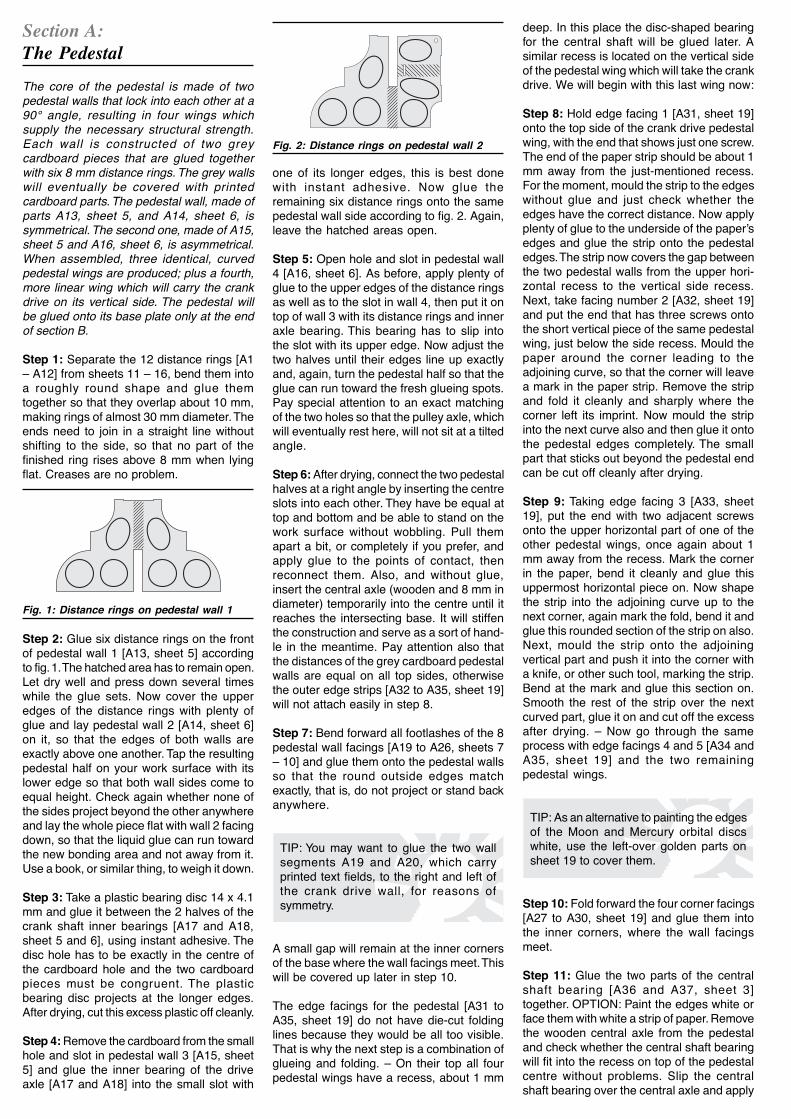
Section A:The Pedestal The core of the pedestal is made of twopedestal walls that lock into each other at a90° angle, resulting in four wings whichsupply the necessary structural strength.Each wall is constructed of two greycardboard pieces that are glued togetherwith six 8 mm distance rings. The grey wallswill eventually be covered with printedcardboard parts. The pedestal wall, made ofparts A13, sheet 5, and A14, sheet 6, issymmetrical. The second one, made of A15,sheet 5 and A16, sheet 6, is asymmetrical.When assembled, three identical, curvedpedestal wings are produced; plus a fourth,more linear wing which will carry the crankdrive on its vertical side. The pedestal willbe glued onto its base plate only at the endof section B. Step 1: Separate the 12 distance rings [A1– A12] from sheets 11 – 16, bend them intoa roughly round shape and glue themtogether so that they overlap about 10 mm,making rings of almost 30 mm diameter. Theends need to join in a straight line withoutshifting to the side, so that no part of thefinished ring rises above 8 mm when lyingflat. Creases are no problem.
deep. In this place the disc-shaped bearingfor the central shaft will be glued later. Asimilar recess is located on the vertical sideof the pedestal wing which will take the crankdrive. We will begin with this last wing now: Step 8: Hold edge facing 1 [A31, sheet 19]onto the top side of the crank drive pedestalwing, with the end that shows just one screw.The end of the paper strip should be about 1mm away from the just-mentioned recess.For the moment, mould the strip to the edgeswithout glue and just check whether theedges have the correct distance. Now applyplenty of glue to the underside of the paper’sedges and glue the strip onto the pedestaledges. The strip now covers the gap betweenthe two pedestal walls from the upper hori-zontal recess to the vertical side recess.Next, take facing number 2 [A32, sheet 19]and put the end that has three screws ontothe short vertical piece of the same pedestalwing, just below the side recess. Mould thepaper around the corner leading to theadjoining curve, so that the corner will leavea mark in the paper strip. Remove the stripand fold it cleanly and sharply where thecorner left its imprint. Now mould the stripinto the next curve also and then glue it ontothe pedestal edges completely. The smallpart that sticks out beyond the pedestal endcan be cut off cleanly after drying. Step 9: Taking edge facing 3 [A33, sheet19], put the end with two adjacent screwsonto the upper horizontal part of one of theother pedestal wings, once again about 1mm away from the recess. Mark the cornerin the paper, bend it cleanly and glue thisuppermost horizontal piece on. Now shapethe strip into the adjoining curve up to thenext corner, again mark the fold, bend it andglue this rounded section of the strip on also.Next, mould the strip onto the adjoiningvertical part and push it into the corner witha knife, or other such tool, marking the strip.Bend at the mark and glue this section on.Smooth the rest of the strip over the nextcurved part, glue it on and cut off the excessafter drying. – Now go through the sameprocess with edge facings 4 and 5 [A34 andA35, sheet 19] and the two remainingpedestal wings.
TIP: As an alternative to painting the edgesof the Moon and Mercury orbital discswhite, use the left-over golden parts onsheet 19 to cover them.
Step 10: Fold forward the four corner facings[A27 to A30, sheet 19] and glue them intothe inner corners, where the wall facingsmeet. Step 11: Glue the two parts of the centralshaft bearing [A36 and A37, sheet 3]together. OPTION: Paint the edges white orface them with white a strip of paper. Removethe wooden central axle from the pedestaland check whether the central shaft bearingwill fit into the recess on top of the pedestalcentre without problems. Slip the centralshaft bearing over the central axle and apply
Step 2: Glue six distance rings on the frontof pedestal wall 1 [A13, sheet 5] accordingto fig. 1. The hatched area has to remain open.Let dry well and press down several timeswhile the glue sets. Now cover the upperedges of the distance rings with plenty ofglue and lay pedestal wall 2 [A14, sheet 6]on it, so that the edges of both walls areexactly above one another. Tap the resultingpedestal half on your work surface with itslower edge so that both wall sides come toequal height. Check again whether none ofthe sides project beyond the other anywhereand lay the whole piece flat with wall 2 facingdown, so that the liquid glue can run towardthe new bonding area and not away from it.Use a book, or similar thing, to weigh it down. Step 3: Take a plastic bearing disc 14 x 4.1mm and glue it between the 2 halves of thecrank shaft inner bearings [A17 and A18,sheet 5 and 6], using instant adhesive. Thedisc hole has to be exactly in the centre ofthe cardboard hole and the two cardboardpieces must be congruent. The plasticbearing disc projects at the longer edges.After drying, cut this excess plastic off cleanly. Step 4: Remove the cardboard from the smallhole and slot in pedestal wall 3 [A15, sheet5] and glue the inner bearing of the driveaxle [A17 and A18] into the small slot with
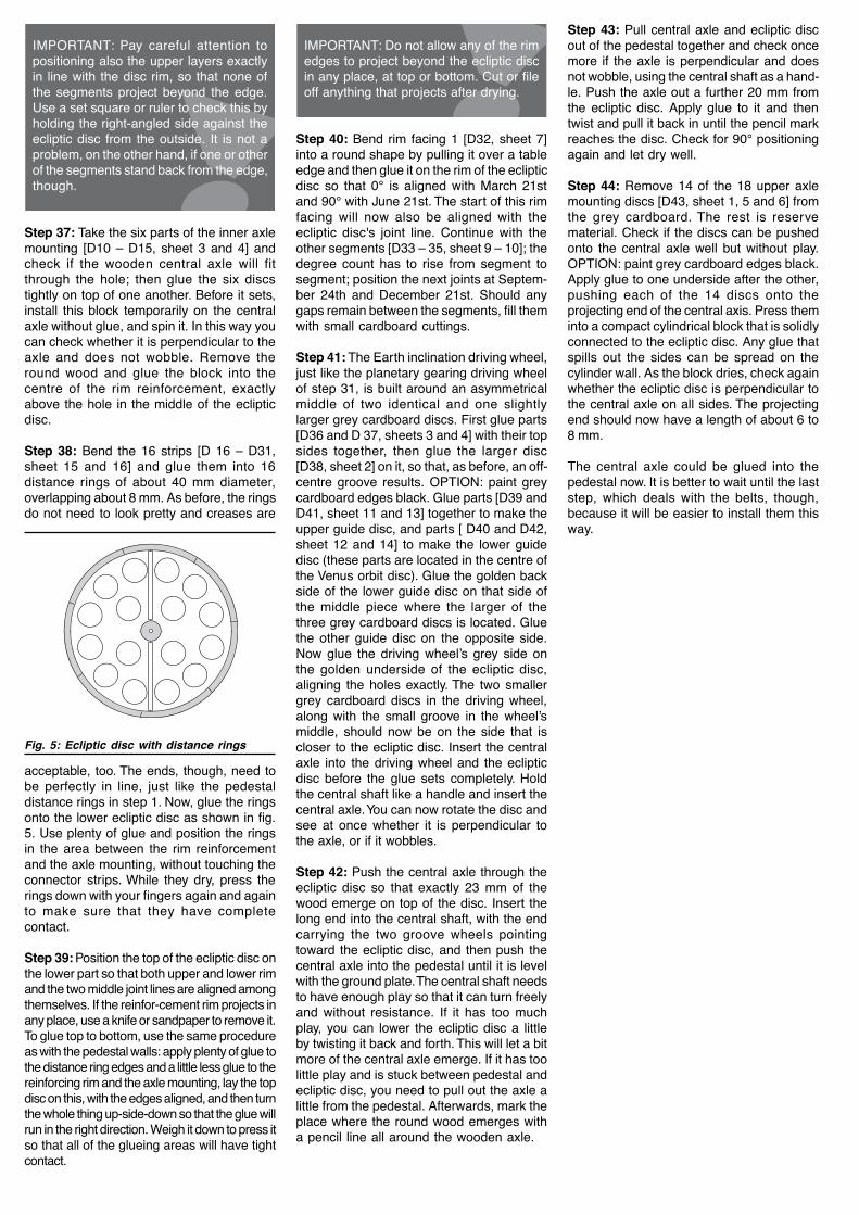
one of its longer edges, this is best donewith instant adhesive. Now glue theremaining six distance rings onto the samepedestal wall side according to fig. 2. Again,leave the hatched areas open. Step 5: Open hole and slot in pedestal wall4 [A16, sheet 6]. As before, apply plenty ofglue to the upper edges of the distance ringsas well as to the slot in wall 4, then put it ontop of wall 3 with its distance rings and inneraxle bearing. This bearing has to slip intothe slot with its upper edge. Now adjust thetwo halves until their edges line up exactlyand, again, turn the pedestal half so that theglue can run toward the fresh glueing spots.Pay special attention to an exact matchingof the two holes so that the pulley axle, whichwill eventually rest here, will not sit at a tiltedangle. Step 6: After drying, connect the two pedestalhalves at a right angle by inserting the centreslots into each other. They have be equal attop and bottom and be able to stand on thework surface without wobbling. Pull themapart a bit, or completely if you prefer, andapply glue to the points of contact, thenreconnect them. Also, and without glue,insert the central axle (wooden and 8 mm indiameter) temporarily into the centre until itreaches the intersecting base. It will stiffenthe construction and serve as a sort of hand-le in the meantime. Pay attention also thatthe distances of the grey cardboard pedestalwalls are equal on all top sides, otherwisethe outer edge strips [A32 to A35, sheet 19]will not attach easily in step 8. Step 7: Bend forward all footlashes of the 8pedestal wall facings [A19 to A26, sheets 7– 10] and glue them onto the pedestal wallsso that the round outside edges matchexactly, that is, do not project or stand backanywhere.
TIP: You may want to glue the two wallsegments A19 and A20, which carryprinted text fields, to the right and left ofthe crank drive wall, for reasons ofsymmetry.
A small gap will remain at the inner cornersof the base where the wall facings meet. Thiswill be covered up later in step 10. The edge facings for the pedestal [A31 toA35, sheet 19] do not have die-cut foldinglines because they would be all too visible.That is why the next step is a combination ofglueing and folding. – On their top all fourpedestal wings have a recess, about 1 mm
Fig. 1: Distance rings on pedestal wall 1
Fig. 2: Distance rings on pedestal wall 2

Section B:The Crank Drive The belt drive wheels are all built basicallyin the same way: their core consists of 2 to 4grey cardboard discs (“middle”) coming tothe same thickness as the belt that will runon them. Guiding the belt is a larger disc thatis glued on each side and made of two layers(“inner” and “outer”) of printed whitecardboard. The crank drive itself is made ofthe driving wheel with its arm and handle aswell as two pulleys. Motion is transferred tothe central shaft runner by a belt of 4 mmdiameter; which is why the middle parts ofthe involved wheels are built of four greycardboard discs (see fig. 3).
glue a small plastic bearing disc 14 x 4.1mm onto each outer face with instantadhesive, also centring it precisely. Afterdrying, install the pulley on the wooden axleand test whether the hole in the bearingdiscs is large enough to allow easy turning.If necessary, widen the hole as describedbefore. – Repeat all with pulley 2 [parts B11to B14, sheet 4 and B15 to B18, sheets 8and 10]. Step 15: Dab a bit of oil on the areas of theaxle where the plastic discs will have contact,to prevent squeaking. Install both pulleys onthe wooden axle. Now glue one stopper [B19and B20, sheet 19] on each projecting axleend, to keep the pulleys from falling off. Dothis in the same fashion as before with thepulley axle covers. Be careful that the pulleysretain enough room between cover andstopper and are able to turn without friction.Finally, glue facings 1 and 2 [B21 and B22,sheet 19] on the ends of the pulley axle. The driving wheel of the crank drive consistsof a groove wheel, the glued-on crank armwith its handle and the crank shaft: a 56 mmlong round wooden piece, glued into thecentre the groove wheel. One of the crankshaft bearings is already installed inside thepedestal, the second one will be glued tothe outside. Step 16: Glue together the two parts of theouter crankshaft bearing [A42 and A43,sheet 4] and make sure that it fits into theside recess of the pedestal edge, below thepulleys, without trouble. OPTION: paintedges white or face with a white paper strip.Now glue one of the plastic bearing discs(25 x 4.1 mm) on one side of the outercrankshaft bearing.
IMPORTANT: The bearing is not to beglued on yet.
Step 17: Build the middle part of the drivingwheel for the crank drive by glueing togetherthe four parts [B23 to B26, sheet 5 and 6].OPTION: paint edges black. Construct the
glue to the edges of the pedestal walls wherethe bearing will be. Insert the central axleinto the pedestal again and push the bearingdown until it fits exactly into its place abovethe intersecting pedestal walls. It will servenot only as the bearing for the central shaftthat turns on the central axle, but will alsogive the needed support for the central axle.Now glue its four facings [A38 to A41, sheet15 and 16] onto the underside of the centralshaft bearing. The pedestal is now prepared to take thecrank drive.
Step 12: Push the 70 mm long wood piecethrough the hole at the top of the pedestalwing so that it projects equally on both sides.You may have to widen the holes a bit. Thisis the pulley axle. With a pencil, mark theaxle on both sides where it exits from thecardboard, and make sure that these marksare equally far from the ends. Check alsothat the axle is at a right angle to the pedestalwing. Now pull the wooden piece out for 5 or10 mm, apply glue to this area and push itback in while turning it. Push it beyond themark so that glue can be applied to the otherside as well and then push it back to its ori-ginal position. The pencil marks should nowboth be visible and the axle must projectequally on both sides. Allow to dry. Step 13: Wrap the pulley axle covers 1 and2 [B1 and B2, sheet 19] around one of theremaining round wooden sticks without glueso that the paper strip will bend; this makesthem easier to glue on. Now glue the greyend of one of the strips onto the pulley axlewith the first few millimetres of its backside,directly next to the pedestal wall. Allow thisto set and then put glue on the rest of thestrip. Wrap it tightly into a solid, gluedcylinder and push it against the pedestal wallwith pressure before the glue sets, using oneof the 14 x 4.1 mm plastic bearing discs. Usethe same procedure for the paper strip onthe other side of the pulley axle. The ends ofthe two axle covers will now be about 40mm apart. This determines the correctdistance between the pulleys. Step 14: Remove the four middle parts ofpulley 1 [B3 to B6, sheet 3] from the greycardboard. First glue two parts against oneanother with their upper sides and then glueanother part onto each side, again with itsupper side. OPTION: paint edges black. Takecare that the discs are congruent. Next, glueouter disc 1 of pulley 1 [B7, sheet 7] on theback of its matching and identical inner disc[B9, sheet 9] and repeat all with outer disc 2[B8, sheet 7] and inner disc 2 [B10, sheet 9].Glue the two double-layered side parts onboth sides of the four-layered grey cardboardmiddle. As you do this, check whether middleand side parts are all centred exactly. Next,
Fig. 3: Pedestal with crank drive

front side of the driving wheel from parts [B27and B29, sheet 11 and 13] and the backside from parts [B28 and B30, sheet 12 and14]. Now glue front and back on the four-layered grey cardboard middle, aligningthem well. Step 18: With a pencil, make a mark exactly11 mm from the end of one of the 56 mmlong round wooden sticks. Take the crankshaftstopper [B31, sheet 19] and roll it over thestick so that it will bend well. Next, wrap andglue the strip next to the mark on the wood,leaving 11 mm free on one side. Push this11 mm long end through the opening in thecrankshaft bearing from behind, so thatabout 10.5 mm of wood project from theplastic bearing disc. Without glue, insert thiswood end into the hole on the black backside of the driving wheel, so that it comesabout 4 mm out of the front side. This way,the driving wheel is secured in its place onthe outer crankshaft bearing by the stopper.It must be able to turn freely and easily, withnot too much but also not too little leeway.Pull the wooden crank shaft out again andglue it into the position that you just tested.The crank arm will later be glued onto the 4mm end of the projecting crank shaft. Step 19: Insert the long end of the crankshaftinto the side opening of the pedestal so thatit locks into the central bearing, which isalready glued into the pedestal wall andhidden from view. The outer crankshaftbearing will then slip into the side recess ofthe pedestal. Now apply some oil to thoseplaces on the wooden axle where the innerand outer plastic bearing discs have contactand glue the bearing on the pedestal walledges in this position. Cover the remainingvisible portions of the grey cardboard discwith facings 1 and 2 [A44 and A45, sheet 15and 16]. Now the pedestal can be glued on the baseplate: Step 20: Mark the fibre direction, meaningthe direction in which the cardboard iseasier to bend, of parts [A47 and A48, sheet15 and 16], the top and bottom side of thebase plate. It is best to draw a line, runningin the same direction, on the back of bothparts, even before separating them from thesheet. Glue the two parts on both sides ofthe grey cardboard base plate [A46, sheet2], in such a way that their fibre directionruns parallel. OPTION: colour edges whiteor face with white paper strips. Press welland long to prevent any warping of thebaseplate. Step 21: Push the central axle through thepedestal until half of it emerges at the bottom.Apply glue to the pedestal’s glueing lashes,insert the end of the central axle into thehole in the base plate and push the pedestaldown until the glueing lashes reach theirdestinations. Adjust the pedestal exactly andpress lightly. After drying you can removethe central axle again.
IMPORTANT: The central axle is not to beglued in yet.
Step 22: As long as the central axle is notglued in, you can use it for shaping the sunglobe bearing [K1, sheet 19]. In order toshape the paper strip into a tube, first wrap itaround the wooden axle without glue to bendit. The black end should form the last bit. Nowwrap the first turn without glue, then applyonly a bit of glue and allow this portion todry. Your care will achieve a close fit betweenwood and tube while allowing enough playfor the tube to be pulled off easily. Now finishwrapping and glueing the strip into its tubeshape and lay it aside; it will be needed onlyat the very end. Step 23: Glue the four middle parts of thecrank arm [B32 to B35, sheet 5 and 6]together. OPTION: paint the grey cardboardedges white or face with white paper strips.Glue the back and front [B36 and B37, sheet15 and 16] on them. The crank arm has alarger wheel at one end, a small one at theother. Without glue, insert the crank handleaxle (the 38 mm wooden stick) into the holeof the small wheel. Push the cover [B38,sheet 19] for the crank handle axle over thewood piece onto the crank arm and glue it inplace. Step 24: The paper strip for the crank hand-le axle (B39, sheet 19) must be wrappedand glued into a tube. It has to be able toturn on the wooden axle with a bit of play;therefore you need to first enlarge the roundwood diameter a little. Use the last remaining56 mm wood piece (the future Earth rotationshaft) as a wrapping tool and tape two layersof newspaper (or one layer of normal paper)around it with sellotape. Now wrap the paperstrip once completely around this core, sothat it is bent well. To begin now, wrap just alittle more than one turn on the core andglue this piece to itself only.
IMPORTANT: Make sure that the tube isstill moveable on the core and does notbond with it as you work on it.
Then wrap and glue the whole strip on andcheck that the layer edges are well aligned.After drying, pull off the finished capsule andalso remove the additional paper from theround wood. Push the tube onto the crankhandle axle.
TIP: if you intend to use the planetariumoften, we recommend to wrap sellotapearound the handle tube; this will protectthe colours.
Section C:The Central Shaft The central shaft turns around the centralaxle. Its task is to receive the power comingfrom the crank drive by the running wheel atits lower end, and to pass it on to theplanetary gearing at two differing speeds byway of the two driving wheels at its upperend. The core of the central shaft consists ofthe 100 x 12 mm cardboard tube (see fig. 4). Step 27: Glue together the four-layeredmiddle of the central shaft running wheelfrom parts [C1 to 4, sheets 5 and 6]. Beforeglueing, check whether the cardboard tubefits into every disc hole. If necessary, widenthe hole as described at the start and/or sandthe end of the cardboard tube. OPTION: paintthe grey cardboard edges black.
Step 25: Glue the tube stopper [B40, sheet19] on the projecting wood end of the hand-le axle. For this it’s best to pull the axle fromthe crank arm once more. Wrap and gluethe stopper around the wooden axle end,aligning it with the edge, in the same manneras before (bending the paper, attaching theend with glue, wrapping and glueing therest). Push the tube back on the axle andglue the wooden axle in its matching hole inthe crank handle, just deep enough so thatthe tube can still turn easily with a bit ofleeway. Glue the covers [B41 and B42, sheet19] on both ends of the crank handle axle. Step 26: Glue the crank handle on the drivingwheel of the crank drive. The crank shaft end,which sticks out of the driving wheel centre,will enter into the crank handle hole. Glue itscover [B43, sheet 11] on this hole. The crank drive is now finished. Next will bethe central shaft which it drives.

With most of the groove wheels of the beltdrive, the 2 mm drive belt leaves the wheelin a straight line. In these cases, the middlepart of the groove wheel consists of twolayers of grey cardboard, producing asufficient space of 2.3 mm. The belt thatdrives the planetary transmission needs tobe slanted, though, in order to connect thegrooved wheels. To prevent its jumping thewheel, the grooves of both driving wheel andrunner need to be wider. They are thereforebuilt of three cardboard discs. One of theseis a little larger than the others, providing aslightly asymmetrical running surface withinthe wheel. Step 31: Build the driving wheel for theplanetary gearing by, first of all, glueing themiddle parts [C15 and C16, sheet 2] againstone another with their upper sides, so that asmall groove between the edges results.Now glue on the third middle part [C17, sheet2], which is a bit larger, with its upper side.OPTION: paint the grey cardboard edgesblack. The small groove is now slightly off-centre in the three-layered disc. After drying,see to it that the cardboard central shaft fitswell into the hole. Next, glue the top andbottom of the guide discs [C18 and C19,sheet 11 and 12] on their inner parts [C20and C21, sheet 13 and 14]. The guide discwith gold printing should then be glued, well-centred, on the larger of the three greycardboard discs; glue the second guide discon the other side of the middle part. Step 32: Lay the earth rotation driving wheelbuilt in step 30 on your work surface with thegrey glueing area looking up and glue thejust constructed planetary gearing drivingwheel on it, well centred. The side with goldprint is on top, and next to it, the larger of thethree grey cardboard discs. After drying,make sure that the central shaft fits into thehole and then glue the remaining plasticbearing disc (20 x 8.1 mm) on the centre ofthe small planetary gearing driving wheelwith instant adhesive. Next, glue the twoconnected groove wheels on the free end ofthe cardboard tube so that the tube touchesthe plastic bearing disc. The wheels must beat an exact right angle to the cardboard tubeand not tilted. To check this, you can put thecentral shaft on the central axle and spin it. Step 33: Bend the central shaft facing [C22,sheet 19] by wrapping it around a pencil oraround the central axle; then glue it on thecentral shaft cardboard tube. First glue ononly the backside of the grey end, then wrapand glue the rest on. The central shaft is now finished.
Fig. 4: Central shaft
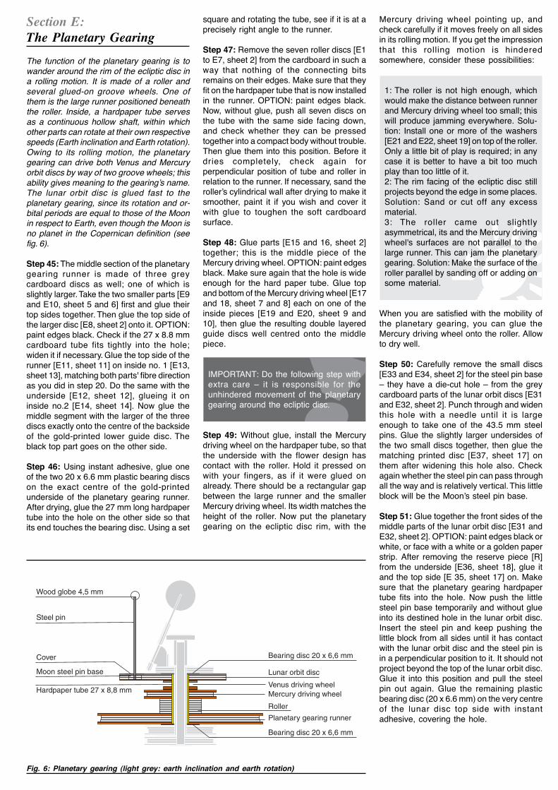
Section D:The Ecliptic Disc The ecliptic disc determines the distance tothe planetary gearing, which moves in acircular motion along the outer rim of theplanetary gearing, as if on a rail. The rubberbelts that press the planetary gearing againstthe outer rim exert considerable pressureon the ecliptic disc. In addition, the weight ofthe moving planetary gearing provideschanging, irregular forces. Three structuralfeatures enable the ecliptic disc to withstandthese potent stress factors: A solid rimreinforcement made of grey cardboard, alight yet torsion-free hollow construction anda solid mounting on the central axis. Step 34: Lay the upper halves of the eclipticdisc [D1 and D2, sheet 7 and 8] side by sideon your work surface, printed side facingdown. The two halves will now be gluedtogether using connector strips [D5 and D6,sheet 11 and 12]. Before you do this, make apencil mark at each end of the line dividingthe two halves – 10 mm from the rim. Theconnector pieces have to keep clear of thismark to leave room for the grey cardboardreinforcement that will run around the rim.Now glue the connector strips first on onlyone of the disc halves, parallel to the dividingline and leaving half of the strip projectingout. The distance to the rim is 10 mm, to thedisc centre a good 18 mm. Now turn the dischalves face up, apply glue to the projectingconnectors and lay the second disc half onthem so that the rim edges meet exactly anda perfectly circular disc results. Repeat thisprocedure with the underside of the eclipticdisc [D3 and D4, sheet 9 and 10] and itsconnectors [D7 and D8, sheet 13 and 14].The disc with the signs of the zodiac willbecome the top part of the ecliptic disc. Step 35: Remove the 42 rim reinforcements[D9, sheet 1] from the grey sheet, taking careto remove all of the small connector residue,so that the curved outside edge is clean. Inthe next step you will glue these 42 piecesinto six ring-like layers of 7 pieces each,forming a solid rim between the top andbottom part of the ecliptic disc.
IMPORTANT: Take care that your worksurface is perfectly plane, to prevent anywarping of the ecliptic disc during glueing.
Step 36: Glue the first reinforcing piece onthe back of the ecliptic disc so that it bridgesthe middle joining line. Its outer curved edgehas to be in line with the outer rim of theecliptic disc. Now glue on the other 6 piecesthat form the first layer, without any gapsbetween them. As you glue all the otherpieces into mounting layers, bridge theunderlying joints by shifting the pieces, asyou would when laying bricks.
Step 28: Glue the top side [C5, sheet 11]and the downside [C6, sheet 12] of therunning wheel each to one of the insides[C7 and C8, sheet 13 and 14]. Now gluethese double-layered guide discs on bothsides of the central shaft running wheel,centring them precisely. Glue a plasticbearing disc (20 x 8.1 mm) on the blackunderside centre with instant adhesive. Step 29: Insert the 10 cm cardboard tubeinto the top side of the running wheel so thatit touches the bearing disc and stands at aright angle on the running wheel. Check thisangle with a set square or paper corner. Thenglue the cardboard tube into this position inthe running wheel.
TIP: You will see at once whether the wheelis tilted or at a right angle to the cardboardtube if you put wheel and tube on thecentral axle in the pedestal and spin it.
Step 30: Glue together parts [C9 and C10,sheet 2] to build the middle of the Earthrotation driving wheel. Check whether thecardboard tube fits into the hole and doadjustments if necessary. OPTION: paint thegrey cardboard edges black. Glue togetherthe side guide discs: top and bottom parts[C11 and C12, sheet 11 and 12] and twoinner parts [C13 and C14, sheets 13 and14]. Then glue the guide discs on both sidesof the grey cardboard middle.
Step 43: Pull central axle and ecliptic discout of the pedestal together and check oncemore if the axle is perpendicular and doesnot wobble, using the central shaft as a hand-le. Push the axle out a further 20 mm fromthe ecliptic disc. Apply glue to it and thentwist and pull it back in until the pencil markreaches the disc. Check for 90° positioningagain and let dry well. Step 44: Remove 14 of the 18 upper axlemounting discs [D43, sheet 1, 5 and 6] fromthe grey cardboard. The rest is reservematerial. Check if the discs can be pushedonto the central axle well but without play.OPTION: paint grey cardboard edges black.Apply glue to one underside after the other,pushing each of the 14 discs onto theprojecting end of the central axis. Press theminto a compact cylindrical block that is solidlyconnected to the ecliptic disc. Any glue thatspills out the sides can be spread on thecylinder wall. As the block dries, check againwhether the ecliptic disc is perpendicular tothe central axle on all sides. The projectingend should now have a length of about 6 to8 mm. The central axle could be glued into thepedestal now. It is better to wait until the laststep, which deals with the belts, though,because it will be easier to install them thisway.
IMPORTANT: Pay careful attention topositioning also the upper layers exactlyin line with the disc rim, so that none ofthe segments project beyond the edge.Use a set square or ruler to check this byholding the right-angled side against theecliptic disc from the outside. It is not aproblem, on the other hand, if one or otherof the segments stand back from the edge,though.
Step 37: Take the six parts of the inner axlemounting [D10 – D15, sheet 3 and 4] andcheck if the wooden central axle will fitthrough the hole; then glue the six discstightly on top of one another. Before it sets,install this block temporarily on the centralaxle without glue, and spin it. In this way youcan check whether it is perpendicular to theaxle and does not wobble. Remove theround wood and glue the block into thecentre of the rim reinforcement, exactlyabove the hole in the middle of the eclipticdisc.
Step 38: Bend the 16 strips [D 16 – D31,sheet 15 and 16] and glue them into 16distance rings of about 40 mm diameter,overlapping about 8 mm. As before, the ringsdo not need to look pretty and creases are
IMPORTANT: Do not allow any of the rimedges to project beyond the ecliptic discin any place, at top or bottom. Cut or fileoff anything that projects after drying.
Step 40: Bend rim facing 1 [D32, sheet 7]into a round shape by pulling it over a tableedge and then glue it on the rim of the eclipticdisc so that 0° is aligned with March 21stand 90° with June 21st. The start of this rimfacing will now also be aligned with theecliptic disc's joint line. Continue with theother segments [D33 – 35, sheet 9 – 10]; thedegree count has to rise from segment tosegment; position the next joints at Septem-ber 24th and December 21st. Should anygaps remain between the segments, fill themwith small cardboard cuttings. Step 41: The Earth inclination driving wheel,just like the planetary gearing driving wheelof step 31, is built around an asymmetricalmiddle of two identical and one slightlylarger grey cardboard discs. First glue parts[D36 and D 37, sheets 3 and 4] with their topsides together, then glue the larger disc[D38, sheet 2] on it, so that, as before, an off-centre groove results. OPTION: paint greycardboard edges black. Glue parts [D39 andD41, sheet 11 and 13] together to make theupper guide disc, and parts [ D40 and D42,sheet 12 and 14] to make the lower guidedisc (these parts are located in the centre ofthe Venus orbit disc). Glue the golden backside of the lower guide disc on that side ofthe middle piece where the larger of thethree grey cardboard discs is located. Gluethe other guide disc on the opposite side.Now glue the driving wheel’s grey side onthe golden underside of the ecliptic disc,aligning the holes exactly. The two smallergrey cardboard discs in the driving wheel,along with the small groove in the wheel’smiddle, should now be on the side that iscloser to the ecliptic disc. Insert the centralaxle into the driving wheel and the eclipticdisc before the glue sets completely. Holdthe central shaft like a handle and insert thecentral axle. You can now rotate the disc andsee at once whether it is perpendicular tothe axle, or if it wobbles. Step 42: Push the central axle through theecliptic disc so that exactly 23 mm of thewood emerge on top of the disc. Insert thelong end into the central shaft, with the endcarrying the two groove wheels pointingtoward the ecliptic disc, and then push thecentral axle into the pedestal until it is levelwith the ground plate. The central shaft needsto have enough play so that it can turn freelyand without resistance. If it has too muchplay, you can lower the ecliptic disc a littleby twisting it back and forth. This will let a bitmore of the central axle emerge. If it has toolittle play and is stuck between pedestal andecliptic disc, you need to pull out the axle alittle from the pedestal. Afterwards, mark theplace where the round wood emerges witha pencil line all around the wooden axle.
Fig. 5: Ecliptic disc with distance rings
acceptable, too. The ends, though, need tobe perfectly in line, just like the pedestaldistance rings in step 1. Now, glue the ringsonto the lower ecliptic disc as shown in fig.5. Use plenty of glue and position the ringsin the area between the rim reinforcementand the axle mounting, without touching theconnector strips. While they dry, press therings down with your fingers again and againto make sure that they have completecontact. Step 39: Position the top of the ecliptic disc onthe lower part so that both upper and lower rimand the two middle joint lines are aligned amongthemselves. If the reinfor-cement rim projects inany place, use a knife or sandpaper to remove it.To glue top to bottom, use the same procedureas with the pedestal walls: apply plenty of glue tothe distance ring edges and a little less glue to thereinforcing rim and the axle mounting, lay the topdisc on this, with the edges aligned, and then turnthe whole thing up-side-down so that the glue willrun in the right direction. Weigh it down to press itso that all of the glueing areas will have tightcontact.
Section E:The Planetary Gearing The function of the planetary gearing is towander around the rim of the ecliptic disc ina rolling motion. It is made of a roller andseveral glued-on groove wheels. One ofthem is the large runner positioned beneaththe roller. Inside, a hardpaper tube servesas a continuous hollow shaft, within whichother parts can rotate at their own respectivespeeds (Earth inclination and Earth rotation).Owing to its rolling motion, the planetarygearing can drive both Venus and Mercuryorbit discs by way of two groove wheels; thisability gives meaning to the gearing’s name.The lunar orbit disc is glued fast to theplanetary gearing, since its rotation and or-bital periods are equal to those of the Moonin respect to Earth, even though the Moon isno planet in the Copernican definition (seefig. 6). Step 45: The middle section of the planetarygearing runner is made of three greycardboard discs as well; one of which isslightly larger. Take the two smaller parts [E9and E10, sheet 5 and 6] first and glue theirtop sides together. Then glue the top side ofthe larger disc [E8, sheet 2] onto it. OPTION:paint edges black. Check if the 27 x 8.8 mmcardboard tube fits tightly into the hole;widen it if necessary. Glue the top side of therunner [E11, sheet 11] on inside no. 1 [E13,sheet 13], matching both parts' fibre directionas you did in step 20. Do the same with theunderside [E12, sheet 12], glueing it oninside no.2 [E14, sheet 14]. Now glue themiddle segment with the larger of the threediscs exactly onto the centre of the backsideof the gold-printed lower guide disc. Theblack top part goes on the other side. Step 46: Using instant adhesive, glue oneof the two 20 x 6.6 mm plastic bearing discson the exact centre of the gold-printedunderside of the planetary gearing runner.After drying, glue the 27 mm long hardpapertube into the hole on the other side so thatits end touches the bearing disc. Using a set
square and rotating the tube, see if it is at aprecisely right angle to the runner.
Step 47: Remove the seven roller discs [E1to E7, sheet 2] from the cardboard in such away that nothing of the connecting bitsremains on their edges. Make sure that theyfit on the hardpaper tube that is now installedin the runner. OPTION: paint edges black.Now, without glue, push all seven discs onthe tube with the same side facing down,and check whether they can be pressedtogether into a compact body without trouble.Then glue them into this position. Before itdries completely, check again forperpendicular position of tube and roller inrelation to the runner. If necessary, sand theroller’s cylindrical wall after drying to make itsmoother, paint it if you wish and cover itwith glue to toughen the soft cardboardsurface. Step 48: Glue parts [E15 and 16, sheet 2]together; this is the middle piece of theMercury driving wheel. OPTION: paint edgesblack. Make sure again that the hole is wideenough for the hard paper tube. Glue topand bottom of the Mercury driving wheel [E17and 18, sheet 7 and 8] each on one of theinside pieces [E19 and E20, sheet 9 and10], then glue the resulting double layeredguide discs well centred onto the middlepiece.
IMPORTANT: Do the following step withextra care – it is responsible for theunhindered movement of the planetarygearing around the ecliptic disc.
Step 49: Without glue, install the Mercurydriving wheel on the hardpaper tube, so thatthe underside with the flower design hascontact with the roller. Hold it pressed onwith your fingers, as if it were glued onalready. There should be a rectangular gapbetween the large runner and the smallerMercury driving wheel. Its width matches theheight of the roller. Now put the planetarygearing on the ecliptic disc rim, with the
Fig. 6: Planetary gearing (light grey: earth inclination and earth rotation)
Mercury driving wheel pointing up, andcheck carefully if it moves freely on all sidesin its rolling motion. If you get the impressionthat this rolling motion is hinderedsomewhere, consider these possibilities:
1: The roller is not high enough, whichwould make the distance between runnerand Mercury driving wheel too small; thiswill produce jamming everywhere. Solu-tion: Install one or more of the washers[E21 and E22, sheet 19] on top of the roller.Only a little bit of play is required; in anycase it is better to have a bit too muchplay than too little of it.2: The rim facing of the ecliptic disc stillprojects beyond the edge in some places.Solution: Sand or cut off any excessmaterial.3: The roller came out slightlyasymmetrical, its and the Mercury drivingwheel's surfaces are not parallel to thelarge runner. This can jam the planetarygearing. Solution: Make the surface of theroller parallel by sanding off or adding onsome material.
When you are satisfied with the mobility ofthe planetary gearing, you can glue theMercury driving wheel onto the roller. Allowto dry well. Step 50: Carefully remove the small discs[E33 and E34, sheet 2] for the steel pin base– they have a die-cut hole – from the greycardboard parts of the lunar orbit discs [E31and E32, sheet 2]. Punch through and widenthis hole with a needle until it is largeenough to take one of the 43.5 mm steelpins. Glue the slightly larger undersides ofthe two small discs together, then glue thematching printed disc [E37, sheet 17] onthem after widening this hole also. Checkagain whether the steel pin can pass throughall the way and is relatively vertical. This littleblock will be the Moon’s steel pin base. Step 51: Glue together the front sides of themiddle parts of the lunar orbit disc [E31 andE32, sheet 2]. OPTION: paint edges black orwhite, or face with a white or a golden paperstrip. After removing the reserve piece [R]from the underside [E36, sheet 18], glue itand the top side [E 35, sheet 17] on. Makesure that the planetary gearing hardpapertube fits into the hole. Now push the littlesteel pin base temporarily and without glueinto its destined hole in the lunar orbit disc.Insert the steel pin and keep pushing thelittle block from all sides until it has contactwith the lunar orbit disc and the steel pin isin a perpendicular position to it. It should notproject beyond the top of the lunar orbit disc.Glue it into this position and pull the steelpin out again. Glue the remaining plasticbearing disc (20 x 6.6 mm) on the very centreof the lunar disc top side with instantadhesive, covering the hole.

Rückseite
Seitenteil
Seitenteil3 x Innenteil
Section F:The EarthInclination Mechanism As it orbits the sun, the Earth’s inclined axisshould always point in the same direction,as it does in reality. This necessitates a se-parate mechanical device, which connectsthe earth axis base with the stationary centralaxle and synchronizes them. The effect ofthis is that during one orbit the earth axisbase revolves backwards one turn, so to say;which makes it appear to stand still. Strangelyenough, it is hardly ever mentioned thatCopernicus recognized this rotation as athird movement of the earth, beside its dailyrotation and annual orbiting (see fig. 7).
grooves. With a straight cut, take off enoughof the bearing disc so that it keeps about 1mm distance to the grooves when its hole iscentred exactly above the hole in the axisbase. Glue into position with instantadhesive.The earth axis mounting, which will beinstalled on the axis base, has an edge thatis tilted 23.5° from the perpendicular line;this equals Earth’s inclination. It is built ofthree inner pieces and two slightly widerouter parts with side supports, to which theback part will be glued (see fig. 8). Step 55: Glue the three parts of the inneraxis mounting [F5 – F7, sheet 10] togetherto form a small block. Fold both side axismountings [F8 and F9, sheet 10] forward at
Step 54: Glue the middle parts of the axisbase [F1 and F2, sheet 5 and 6] together.The round cut-out areas on the side must beexactly aligned. Use a knife to cut completelythrough the partly die-cut lines on the upperside of the axis base [F3, sheet 17]. Thegrooves that result will take the Earth axismounting later on. The die-cut lines on theunderside of the axis base [F4, sheet 18]will not be cut; this piece could serve as areserve part if a wrong cut were made onthe upper part. Now glue both sides on themiddle part; try to allow as little glue aspossible to run into the cut-out grooves.OPTION: Paint edges black or white or facewith white or golden paper strip. Check if the38 x 6.5 mm hardpaper tube will fit into thehole. Widen it if necessary. Put the last 14 x4.1 mm plastic bearing disc on the centre ofthe upper side. It will cover part of the cut-out
The Venus driving wheel is an exception inthat it does not have a grey cardboard middlesegment; the cardboard tube itself will servethis purpose. You will need only guide discsthis time. Step 52: Glue the inside of the Venus drivingwheel [E25, sheet 11] and its top side [E27,sheet 13] together, then glue this doubleguide disc on the centre of the lunar orbitdisc underside. If necessary, widen this hole,too. Push the four remaining parts of the Ve-nus driving wheel [E26, E28 – E30, sheet12, 14 – 16] without glue on the cardboardtube coming out of the Mercury driving wheeland push the lunar orbit disc on it also. Thereshould be a gap now between the loosediscs below and those discs which are gluedon the lunar orbit disc. This gap should be atleast 2 mm wide so that the drive belt canrun within. Check the gap width with one ofthe provided drive belts. If the gap is too tightand the belt jams, you will have to pull thelunar disc out a little again. If it looks like youhave to pull it too far for a reliable glueing,you can reduce the number of loose discs. Step 53: Remove the lunar orbit and theloose discs from the cardboard tube again.OPTION: paint the cardboard tube blackwhere it will be visible. Then, with glue, pushthe lower Venus driving wheel discs on thecardboard tube and also glue the lunar orbiton top, preserving the pre-determined 2 mmgap for the drive belt. Check whether thelunar orbit keeps parallel to the Mercurydriving wheel by looking from the side andby rotating it. The planetary gearing is now finished andready to receive the earth inclinationmechanism within which the earth rotationshaft moves.
Fig. 7: Earth inclination(light grey: earth rotation)
Fig. 8: Earth axis mounting
the die-cut lines. Each is made of one partthat is similar to the inner mounting pieces,only wider, and a fold-away side support.Now glue the small block between the twosimilar-looking parts of the side pieces sothat they end together at the round lowerback side. At the front, on the sloped edge,will be a groove, because the side piecesproject about 1 mm. This groove is threecardboard layers or about 1.5 mm wide andwill take the brass tube that allows the Earthaxis to turn within it. Now glue the two folded-away side supports onto the back of the axismounting [F10, sheet 10], which shows thesame round cut-outs at its ends. A diagramof the finished axis mounting will show a Twith a short upward stroke and a very widehorizontal bar; it matches with the cut-outgroove on the axis base. Check now if it fitsinto the groove and, if need be, widen it witha sharp knife.
IMPORTANT: The lower edge of the axismounting needs to enter completely intothe groove, otherwise it would sit on thebasis at a tilted angle. The inclination ofthe Earth axis would then be incorrect.
Step 56: First, push the brass tube into theinclined groove in the axis mounting, so thatthe funnel-like end is at the top and finisheswith the cardboard parts. Glue it into thisposition with instant adhesive but do notallow any glue to run into the openings. Nowglue the complete axis mounting into the T-like grooves.
Side partBack partThree inner partsSide part

TIP: Instead of constructing the earth axisstopper from paper as described in thenext step, you can cut off about 3 mm ofthe silicone tube and install it on the Earthaxis end. This is easier to remove, shouldmaintenance work be necessary.
Step 57: Wrap and glue the narrow paperstrip of the Earth axis stopper [F11, sheet19] on the end of one of the steel pins. Asbefore, bend it first by wrapping it on withoutglue. Then first glue on only the short edgewith instant adhesive, followed by wrappingand glueing the rest into a roll with about 3mm diameter that ends at the wire’s tip. Afterdrying, push the wire into the brass tube frombelow. The stopper will keep the Earth axisfrom being pulled out of the brass tube bythe magnetic driving wheel. Now push thesilicone tube onto the steel pin from above,only so far as to allow it to still turn freelywithin the brass tube. Spin the steel pinbetween your fingers to check its ability toturn easily and without hindrance. Removeany possible obstacle. Step 58: Install one of the two 16 mm woodglobes on the end of the steel pin and checkwhether it is exactly above the hole in thecentre of the axis base. If it projects too far,shorten the steel pin with a wire cutter. Youcan glue the globe on already with instantadhesive, but if you wish to paint it, do sobefore glueing the globe in place. Install the38 mm long hardpaper tube in the axis baseand check if it enters easily into the lunarorbit disc and the planetary gearing. Nowglue it into the axis base and check by turningit whether it is perpendicular and does notwobble. Step 59: The Earth inclination runner is builtof three middle parts, one of them slightlylarger than the others. Glue the two smallergrey cardboard pieces [F12 and F13, sheet3 and 4] together with their top sides, thenglue the third, larger piece [F 14, sheet 2] onthem. OPTION: paint edges black. Constructthe upper and lower guide disc from parts[F15 and F17, sheet 15 and 17] and [F16and F18, sheet 16 and 18], then glue thewhite top side onto the larger of the threegrey middle discs; the lower disc, which hasa small grey glueing area, goes on the otherside. Make sure that the 38 mm hardpapertube fits well into the hole. Using instantadhesive, glue the remaining 25 x 4.1 mmplastic bearing disc on the underside of thefinished runner, where the two smaller greycardboard discs are. Now insert thecardboard tube that carries the Earth
Section G:The Earth Rotation Earth axis rotation is caused by aneodymium magnet, which pulls thesilicone-covered steel pin toward its edge,forcing it to rotate as it turns (see fig. 9).
Step 60: Glue the paper strip [G1, sheet 19]into a 12 mm long tube, black on the outside,and with 4 mm internal diameter. Do this inthe same way as before by wrapping itaround the last remaining 56 x 4 mm roundwood. The tube can be quite tight on thewood, but do not allow it to be glued to it inthe least – you have to be able to pull it offafterward. Then, roughen the edge of the 15x 2.5 mm neodymium magnet on one sidewith sandpaper. This will give it a better gripon the earth axis silicone tube. Glue the black
Fig. 9: Earth rotation
paper tube on the unsanded side of themagnet, using instant adhesive. Take careto position the mounting at a 90° position aswell as in the centre of the magnet. Step 61: Construct the middle of the Earthrotation runner from parts [G2 and G3, sheet3 and 4]. OPTION: paint edges black. Nowbuild the top side from parts [G4 and G6,sheet 15 and 16], and the lower side from[G5 and G7, sheet 15 and 16], then gluethem on the middle pieces. Glue the cover[G8, sheet 12] beneath the hole in theunderside and then glue the 56 mm roundwood all the way into the hole. Check if it isat a 90° angle to the runner by turning it.Then glue the cover [G9, sheet 13] on themagnet’s centre. Step 62: From below, push the round woodthrough the hollow Earth inclination shaftand hold the magnet with its paper mountinginto its place up above at the same time. Itwill attract the Earth axis with its edge at once.With a twist, push the wood end that isprojecting at the top, into the tube and thencheck if the mounting is not too long. Thiswould force the magnet into a tilted position.In this case, shorten the paper mounting alittle. Also check the length of the wood; if it istoo long, the runner will have too muchdistance to the Earth inclination runnerabove. In this case, shorten the round wooda little by setting the knife on the wood at thechosen cutting point and rolling the roundwood back and forth. It is alright if the woodis a little shorter than the paper mounting ontop, though.
IMPORTANT: Set the round wood into themagnet mounting without any glue, sothat it is easier to dissemble in caseadjustments or repairs are needed.
TIP: If the mounting is too loose on theround wood, you can apply a thin gluelayer to either the end of the wood or theinside of the paper tube or to both.Remember, though, to let them dry wellbefore reassembly.
The planetary drive, including the integratedmoving elements, is now finished and youcan go on to the inner planets Mercury andVenus.
inclination base into the planetary gearingfrom above. Push the runner onto theprojecting end of the tube, below the gearing.Check if runner and Earth axis base are ableto turn freely. There should be just enoughplay above as well as below to enableunhindered movement. If there is too muchplay, the cardboard tube can be shorteneda little. In those places where the plasticbearing discs will touch the cardboard tube,wrap cello-tape around it to reduce frictionand protect them. Now glue the runner tothe tube and check by rotating it severaltimes whether it is vertical and does notwobble.

Section J:The Venus Orbit Disc For production reasons, the middle piece ofthe Venus orbit disc is ring-shaped; its centrehad to be used for the inner Mercurysegment. Step 65: Construct the middle piece of theVenus orbit disc – which also serves asrunner – from the two large rings [J1 and J2,sheet 3 and 4] by glueing them together withaligned fibre directions, and pressing themwell to prevent any warping. If needed, applyparallel cuts as described in the lastIMPORTANT box. OPTION: paint edgesblack. Mark the fibre direction on the back ofthe orbit disc’s upper side [J3, sheet 11] andinner side 1 [J5, sheet 13]. Remove the smallpart [J11] that belongs to the steel pin basefrom the upper side, and also thecorresponding reserve piece from theunderside. Now glue the upper and innerside together in such a way that the smallholes for the steel pin base lie above eachother. Press well. Do the same with theunderside [J4, sheet 12] and inner side 2[J6, sheet 14], but do not remove the smalldiscs marked [R] and do not place themabove each other when glueing them.
Section H:The Mercury Orbit Disc The Mercury orbit disc cannot be drivendirectly by a belt because it would collidewith 'the steel pin on the Venus orbit disk.Instead, a runner is driven, which isconnected to the Mercury orbit disc that liesabove it by a hollow shaft. The Venus orbitdisc rotates around this shaft in turn (see fig.10). – For production reasons, the upper sideof the Mercury runner has to be assembledfrom the two pieces [H3 and H5], theunderside from parts [H4 and H6].
IMPORTANT: The Mercury and Venusorbits (section J) are the largest greycardboard discs. With their dimensionsas they are, even a little bit of warpingwould be a problem. Before taking thepieces out of the sheets, then, mark theirfibre direction, and let these be parallelwhen you glue the pieces together. Ifneeded, bend them into shape gentlybefore glueing. Allow to dry completelywhile being pressed.If the doubled grey cardboard discs comeout warped despite your best efforts, youcan do the following: apply parallel cuts,1cm apart, on the hollow, concave side,parallel to the valley line, using a cutterand ruler. This takes the tension out of thedisc and you can then bend it into shape,which will be made permanent when thetop and bottom layers are glued on later.
Step 63: Mark the fibre direction on themiddle of the Mercury runner [H1 and H2,sheet 3 and 4], then glue the two piecestogether with aligned fibre directions. Presswell. Mark the fibre direction on the top andbottom side as well as on the inside parts 1and 2 [H3 and H4, H7 and H8, sheet 17 and18], before removing them, by drawing a line
on each one, parallel to the longer edge ofthe sheet. Then, aligning the fibre direction,glue each of the insides against one of thetop and bottom sides. These have a gap,into which you can glue the filler pieces [H5and H6, sheet 17 and 18]. Press and let drywell. Now glue top and bottom sides of theMercury runner on the grey cardboardpieces, so that the sides with the filled gaplie on the outside and the fibre directionsare aligned. Again, press well during drying.Glue the last hardpaper tube (34 x 14.5 mm)into the hole so that it reaches the bottomand is perpendicular to the runner. Now gluethe 50 x 29.3 mm plastic bearing disc overthe hole in its underside, using instantadhesive and centring it well. Step 64: Take the steel pin base pieces [H13and H14, sheet 3 and 4] out of the cardboardmiddle parts of the Mercury orbit disc andwiden the die-cut holes as you did beforewith the lunar orbit. Glue the printedcardboard part [H15, sheet 15] from the topside on them. Assemble the middle segmentof the Mercury orbit from parts [H9 and H10,sheet 3 and 4], pressing them while the gluesets. OPTION: paint edges black or white orface with a white or golden paper strip. Gluethe bottom side [H11 and H12, sheet 15 and16] on this, again pressing well. Now pushthe steel pin base into its hole with glue, sothat the steel pin (which is not to be glued inyet!) is vertical. Check if the disc can beinstalled on the hardpaper tube that isalready in place in the runner; if necessary,widen the hole. Using instant adhesive, gluethe other 50 x 29.3 mm plastic bearing discexactly in the centre of the decorated topside of the Mercury orbit disc. After drying,set the orbit disc on the hardpaper tube andcheck if this ensemble of two discs and onehollow shaft can be installed on the upperaxle mounting of the ecliptic disc. This blockmade of 14 grey cardboard discs will serveas an axle for the two plastic bearing discs. Ifthe bearing discs are too tight and are unable
Figure 10: Mercury and Venus orbit discs (light grey: ecliptic disc with Sun)
to turn, you will have to carefully scrapematerial off the inside. If less than one half ofa grey cardboard disc emerges at the top,you may have to glue one of the reservediscs on it. This can also be done later at anypoint.

Section L:The Drive Belts You can skip the following section becauseyour assembly kit contains pre-fabricateddrive belts. Use this section when you wishto cut and shorten one of the belts or want toconstruct new ones from commerciallyavailable NBR-rubber string of 2 and 4 mmdiameter. Step 70: First, construct the glueing form forconnecting the belts from the grey cardboardparts [L1 – L4, sheet 3 and 4]. Glue the twolarger pieces [L1 and L2] together with theirtop sides; this will be the base. Glue the two
Section K:The Sun Our Sun is represented by the white plasticball, which contains an LED that you canturn with the micro switch in the base. TheSun is connected to the central axle by amagnetic support. Step 69: The paper tube that will now serveas a stopper for the Sun support was alreadymade in step 22. Glue one of the 8 mmmagnets into one of its ends. It has the samedimensions as the central axle, but you maystill have to widen the tube end a bit to fit themagnet in. Afterward, install the tube on thecentral axle. This will also keep the coverunderneath in its place. Set the secondmagnet on it, and on this the Sun globe,which has a flat base for this purpose. Thecentre point of the Sun should now be atabout the same height as that of Earth, whenthe planetary gearing is installed on theecliptic disc rim. Now glue the magnet intothis position underneath the Sun globe withinstant adhesive – but with the right side sothat it does not repel the other magnet. To dothis, sand the battery lid lightly to roughenthe surface, then glue the magnet on this lid– not to the surrounding base, though,otherwise you would not be able to changethe battery later. The Copernicus Planetarium is now finishedexcept for the transmission belts.
side walls [L3 and L4] on it, also with theirtops, and in such a way that the outer edgesalign and a 2 mm gap is made betweenthem.
Step 71: To become familiar with the glueingtechnique, first practice with a piece of the 4mm round belt. Cut the ends of the belt atidentical 45° angles, in order to increase theglueing surface. To do this, lay the ends,facing one another, on your cutting surface,overlapping about 1 cm and directly side byside. Secure them in place with a piece ofsellotape (see fig. 11). Now position a setsquare or ruler on the belt at a 45° angle,push it down to hold the ends in place andthen cut through them with a sharp knife.Remove the tape. You should now have twoidentical oval cuts at the ends. Roughen thesurface up very gently with fine sandpaperand do not touch the cutting surfaces withyour fingers. Step 72: Put one end in the groove of theglueing form with the cut facing up, apply asmall drop of instant adhesive to it and pressthe other cut end on it strongly. The twoglueing surfaces have to be congruent, noedge projecting, and fitting tightly. Hold theends in their place for some time and thenslowly pull the belt out of the glueing board,not by pulling it up but rather by peeling itaway to the side and from your fingers, too.Blow on the glueing area; this makes theglue set quicker. After some time, test thebelt to see if it can withstand a light pullingforce. Step 73: Now cut off 32.5 cm of the 4 mmmaterial and construct the thicker belt in itscorrect length with this. This length includesa 10 mm allowance for the overlap cuts. Step 74: Next, do a few glueing tests withthe 2 mm material also. Avoid producingstrongly curved glueing surfaces and takeinto account that the instant adhesive mayglue the belt to the grey cardboardsurrounding the glueing spot, and also toyour fingers. Always remove the belt bypeeling it away, not by pulling, otherwise thestill fresh glueing joint could come apartagain. Step 75: Now construct five rings out of the2 mm material. For these, cut off the followingbelt lengths – each includes the 10 mmallowance already: 2 x 336 mm, 1 x 375 mm,1 x 450 mm, and 1 x 555 mm. The threesmaller ones will be installed beneath theecliptic disc; the two larger ones are forMercury and Venus.
Step 66: Remove the small steel pin basediscs [J9 and J10, sheet 3 and 4] from thegrey cardboard, widen the pin holes andglue them together. Glue disc [J11], from theupper side, onto the base discs. Now gluethe two mounting pieces for the steel pinbase [J7 and J8, sheet 3 and 4] together.These are disc-shaped, with one cut-off side.Lay the Venus orbit disc with its printed sidedown on your work surface so that the backside faces up. Now glue the steel pin basemounting [J7 and J8] over the small hole sothat the cut side points out toward the rim.Then glue the ring-shaped, grey cardboardmiddle segment on the top side, centring it,and glue the underside on it as well. Presswell while you allow to dry. Step 67: Push and glue the steel pin baseinto its hole from the top and take care againto position the steel pin vertically. Glue thelast two plastic bearing discs (55 x 34.3 mm)on the centre of the top as well as the bottomside of the Venus orbit disc. Take care toarrange them perfectly above each other.Now remove the Mercury orbit, which is notglued on, and check if the Venus disc can beinstalled on the hollow shaft in the Mercuryrunner. Also test its ability to turn freely onthe shaft. If not so, widen the hole a little byscraping off material. Then return the Mercuryorbit to its end position on the hollow shaft. Ifit holds well and tight you do not need toglue it on; this has the advantage that theMercury-Venus-disc unit can bedisassembled when needed. Rememberthat the Mercury orbit disc needs to be veryparallel to its runner. Then set the whole uniton the axle block, which is situated on top ofthe ecliptic disc, and test everything for goodmobility.
TIP: To reduce the wear on the greycardboard axle block through abrasionby the plastic bearing discs, you can coverit with glue once more and wrap cello-tape around this after drying.
Step 68: Glue top and bottom side of theecliptic disc cover [D44 and 45, sheet 17and 18] together, aligning the fibre direction.Install the cover on the short protruding endof the wooden central axle. It should holdwithout glue to keep the Mercury-Venus-uniteasily accessible.
Fig. 11: 45° cuts of belt ends

Section M:Final Steps
TIP: Wipe the belts down with alcohol ora similar cleaner; this increases surfacefriction and makes the belts less likely toslip. Also stretch the rings before installingthem on their wheels. The rubber materialcan easily take stretching up to almostdouble its length. If you have glued therings yourself, stretch them only after theglueing joints have dried completely.Protect them by taking the joint betweenyour fingers and stretching the ring withthe other hand on the opposite side.
Step 76: Pull the central axle out of thepedestal, lay the pre-stretched 4 mm belt aswell as the three smaller of the 2 mm beltson top of it and then insert the axle again. Step 77: You can now glue the central axleinto the pedestal. Pull it out of the pedestal,remove the central shaft and apply a bit ofoil to the spots where the plastic bearingdiscs of the central shaft make contact. Thenreinsert it, together with the central shaft,about halfway into the pedestal. The lowerhalf of the rectangular space that holds thecentral axle has only two walls. Fromunderneath, apply plenty of glue to thesewalls' last centimetres; then, twisting it,reinsert the axle into the pedestal to a depthwhich allows the central shaft free mobility,but with not too much play, as before. Werecommend to align the ecliptic disc’s middlejoint line with the pedestal walls. Allow todry well.
TIP: Once the central axle is glued in, anybelts that need to be exchanged orrepaired have to be pulled over thepedestal. This is more of an effort, but iseasily done if the belts are stretched andperhaps warmed in addition.
Step 78: Pull the thicker belt onto thecrankshaft driving wheel and its pulleys aswell as onto the runner down by the centralshaft. Check if it is set in motion when thecrank handle is turned.
Step 79: Install the planetary gearing on theecliptic disc rim. Pull one of the two smaller,thin rings onto the earth inclination drivingwheel, which is connected to the undersideof the ecliptic disc. Then pull the belt on thesecond runner from the bottom on theplanetary gearing; this one is connected tothe earth inclination base. Lay the other,smaller ring on the small groove wheel atthe top of the central shaft and pull it on thelarge planetary gearing runner. Be awarethat these two belts change levels as theyrun from driving wheel to runner; they crossover when looked at from the side (see fig.12). Before attaching the third belt you need toinstall a counterweight above: Step 80: Pull the smaller of the two largerings onto the Mercury runner, which ishidden from view beneath the Venus orbitdisc, and also onto the Mercury drivingwheel of the planetary gearing, which restson the upper side of the ecliptic disc. To dothis, you may temporarily remove theMercury and Venus orbits, which are notglued on. The Venus orbit itself is connectedto its small driving wheel by the largest belt;this wheel is located directly underneath thelunar orbit disc. Step 81: The last belt is to be put into positionunder the ecliptic disc by pulling it on thetwo remaining earth rotation drive groovediscs. In this case the belt has to be twistedhalf a turn to form a horizontal 8, otherwisethe Earth globe would turn in the wrongdirection and the belt would also be muchtoo loose. If you turn the crank handle now,all parts should move as desired. Solutionsfor possible problems are given in the lastsection. Step 82: Using instant adhesive, glue thethree steel pins into the steel pin bases ofMoon, Venus and Mercury. Before glueing,thread one of the covers [E38, H17 and J13,sheet 11 to 13] on each of the pins; thencover the glueing areas with them. The pinsmust be in a very perpendicular position. Nowinstall the globes on the steel pinstemporarily: Moon (4.5 mm) is the smallest,Mercury (6mm) is medium size and Venus(16 mm) the largest. With instant adhesive,glue them on so that they are all at about the
same level as the imaginary line betweenthe centres of Sun and Earth. If one of thepins is too long, shorten it. If the centre of theSun is higher than that of Earth, you canshorten the tube on which it rests. OPTION: If you wish to paint the globes, doso before glueing them on. For this, bendopen a paper clip and push the globe on itsend. TIP: do not use glossy paints and applya primer coat first, for example with correctingfluid. EARTH: draw in only the equator andfour meridians (lines from pole to pole); orpaint the globe blue and add white cloudlayers (correcting fluid) plus a thin equatorline (“our blue planet”); or indicate thecontinents … there is no limit to what youmay do! MOON: white – this will make theMoon phases more distinctive in the dark.VENUS: copper red (copper is the metaltraditionally associated with Venus); or green(also a traditional association). MERCURY:yellow – one of the traditional colours ofMercury. You have now finished the constructionof the Copernicus Planetarium.Congratulations! With much skill andpatience you have built a valuableastronomical demonstration apparatus.It would surely deserve prominentexhibition, but is even more suitable forshowing, understanding and learningpurposes.
Figure 12: Drive belt installation below the ecliptic disc

Having problems? Here aresome possible solutions: 1. Earth turns the wrong way: Does theEarth rotation belt cross over, like a lying8? 2. The illumined halves of the planets arenot clearly distinguishable: Is the surfaceof the globes rough enough to preventreflecting? Perhaps you need to cover upthe reflecting surfaces of the Mercury andVenus orbit discs for cer taindemonstrations? 3. The orbit times differ strongly from theideal times: Does the transmissionencounter too much resistance in anyplace? Is one of the plastic bearing discstoo tight on its axle? Is there too muchfriction or even jamming in some part ofthe mechanism? 4. The pulleys squeak when cranking:Apply a drop of machine oil, or, even bett-er, silicone oil (do not use edible oils) nextto the bearing discs with a toothpick. 5. The glued joints of the drive belts donot hold (only applies to self-constructedbelts): Do the glueing surfaces have flatcontact? Are they grease-free andsanded lightly? Are you using a good,fresh instant adhesive? If done well, thebonds will withstand even high tension. 6. A slipping drive belt: Are the belts de-greased sufficiently? TIP: If not in use forlonger periods, it is a good idea to takethe belts off; they will then regain theiroriginal tensile force. Replacement beltscan be obtained through the AstroMediacustomer service. 7. A drive belt jumps its groove wheel:perhaps you need to straighten a bentgroove edge and harden it with glue? Isone of the groove wheels at a wrong ang-le, or is it warped? Are there grooves thatare too tight and need to be widened byrunning a blunt-tipped instrument throughthem? Do you have any other suggestions forsolving difficulties? Please send word to:[email protected].
Things you can demonstrate with the Copernicus Planetarium:As observers on Earth, we have the sensation of being in the centre of all that we see. Thisworld view, which was also at the core of antiquity’s concept of the world, is still valid in ourtime, especially in our daily lives, which are ruled by nature’s rhythms. After all, at dawn wespeak of the sunrise and not of the “earth-turn”. Concepts based on the Copernican worldview, though, where the focus of our thinking is moved to the Sun, supply an especiallysimple and plausible physical explanation and are therefore no less valid. If you have clearknowledge about the point from which you observe and explain some object, then you canunderstand and accept both world definitions at the same time. This can be compared totouching a glove – you would sense and describe it very differently depending on how youencountered it: from the inside or the outside.In this sense the Copernicus Planetarium is a useful tool for explaining well-knownphenomena experienced on Earth only, from a point of view that encompasses the wholesolar system. The sizes of Earth, Moon and the planets are represented in correct relation(the Sun’s is not); the distances, though, are nowhere near correct – this would blow anymodel’s proportions. The orbital times are about correct in comparison to astronomical facts.One crank turn will move everything one week further. Please be aware that a belt-driventransmission is always subject to some slip; this produces deviations. ■ The change of night and day and the Sun’s course through the day correspond with the
daily rotation of Earth on its axis. (For technical reasons the Earth globe goes through 5instead of 7 rotations per crank turn, which is hardly noticeable, though.)
■ The course of the year with its change of seasons corresponds with the orbit of Eartharound the Sun (about 52 crank turns). The inclined Earth axis keeps its direction throughoutthe orbital period, this lets the Northern hemisphere receive more light at one time and theSouthern hemisphere at another. To demonstrate this, turn the Earth inclination base untilthe (upper) North pole of the Earth globe points toward the Sun when positioned at theJune 21st marking (summer solstice).
■ The zodiac is the traditional series of twelve star constellations in which the terrestrialobserver sees the Sun in the course of one year.
■ The changing of the Moon phases is caused by the varying position of the Moon inrelation to Earth and Sun. One half of the Moon is illumined by the Sun all of the time, butit shows this half to us only at full moon; at other times we are shown less and nothing atall during new moon. The particular phase symbol on the lunar orbit disc which pointstoward the Sun, indicates the Moon phase visible from Earth at the time. During oneannual Earth orbit, the Moon passes through all of its phases about 12 and 1/3 times (thisequals about four crank turns per month). The Moon always turns the same side towardsEarth.
■ Lunar and solar eclipses happen when the Moon enters Earth’s shadow or when Earth ishit by the Moon’s shadow. Information: Owing to the unavoidably incorrect relative distancesin this model, every full moon position causes a lunar eclipse, while every new moonbrings about a solar eclipse. This, of course, is not so in reality.If you wish to demonstrate only the above phenomena, you can remove the Mercury andVenus orbits. The model would then be called a “Tellurium” – an Earth-Moon-Sun model.The planetary drive would in this case be held in place by the lower drive belts only.
■ Venus is recognized as the morning star when the observer on Earth sees it to the right of
the Sun. It will then rise before the Sun does. We see Venus as the evening star whenpositioned to the left of the Sun; it will then set after it.
■ The phases of Venus can be observed with a telescope only. They appear when only afraction of sunlit Venus is visible from Earth.
■ The superior and inferior conjunctions of Mercury and Venus appear when the planet inquestion is exactly in front of the Sun (inferior) when seen from Earth, or exactly behind it(superior conjunction). Unlike Moon and the so-called outer planets Mars, Jupiter, Saturnand so on, Venus and Mercury can never be in opposition – meaning, in the oppositedirection to the Sun when seen from Earth.
■ The pentagram of Venus conjunctions is made by connecting those points on the zodiacwith each other where Sun and Venus stand during a superior conjunction as seen fromEarth (the same goes for the inferior conjunctions). Generally, this is seen as the reasonfor associating the pentagram symbol with Venus; a connection known since antiquity. Inrelation to the Mercury conjunctions there is a similar connection: the Mercury triangle,though this is not as commonly used.
■ The sidereal orbit time of a planet or of the Moon describes the duration of a completeorbit around the Sun until it reaches the same fixed star (lat. sider) again. Mercury takes88, Venus 225 and the Moon 27 ¼ days for this (as observed from Earth).
■ The synodic orbit time of a planet or of the Moon is the time it takes to reach the sameposition in relation to the Sun again, as seen from Earth. Mercury takes 116, Venus 584and the Moon 29 ½ days (one lunation, the time from new moon to new moon).

Bogen 1
D9
D9
D43 D43 D43 D43 D43 D43
Bogen 2
A46
D38
C9 C10
C15
C16
C17
E1
E2
E3
E4
E5
E6
E7
E8
E15 E16
E31 E32E33 E34
F14
Bogen 3A36
B3
B4
B5
B6A37
D10
D11
D12
D36 F12
G2
H1
H9
H13
J1
J7
J9
L1
L3
Bogen 4
B11
B12
B13
B14
A42
A43
D13
D14
D15
D37 F13
G3
H2
H10
H14
J2
J8
J10
L2
L4
Bogen 5A13
A15A17
B23
B32
B33
B24
C1
C2
D43 D43
D43
D43
D43
D43
E9 F1
(Reserve)
A14
A16A18
B34
B35
B25
B26
C3
C4
D43 D43
D43
D43
D43
D43
E10 F2Bogen 6
(Reserve)