knowledge-based support for innovative design · knowledge-based support for innovative design 5...
TRANSCRIPT
Knowledge-Based Support ForInnovative Design
Valeri V. Souchkov
© Valeri V. Souchkov
University of Twente, Enschede, The Netherlands. 1998
1 Knowledge-Based Support For Innovative Design
Chapter 1. Introduction 5
Subject of this book 5
Research Goals5Book Structure 6Publications 8
Chapter 2. AI and Innovative Engineering Design9
Introduction 9
Fundamentals of Innovative Engineering Design10Overall structure of Design Process11Design concepts and detailed designs13Engineering design and natural sciences14
Conceptual Design 16Phases of Conceptual Design16Design and Creativity: Insight or Science18Systematic versus cognitive approach to conceptual design20
AI and innovative engineering design: related research23Role of AI for Design 23Knowledge Categories in Design23Models of Conceptual Design24Models of Design Based on Cognitive Methods27Models of Design Based on Design Theories28Discussion 33
Chapter 3. The Theory of Inventive Problem Solving35
Introduction 35
TRIZ contents 37Historical background 37Levels of Inventive Solutions38TRIZ Philosophy 39TRIZ Structure 40Technical system 41
Theory of Technical System Evolution42Systematic nature of technology evolution42The law of system ideality43TTSE Laws 44TTSE Trends 44
TRIZ Problem solving techniques47Contradiction as the origin of an inventive problem47Types of Contradictions47Principles of Elimination of Engineering Contradictions48Principles for Physical Contradiction Elimination50Substance-Field Modeling52

Knowledge-Based Support For Innovative Design 2
Pointers to Scientific-Engineering Effects55
Algorithm of Inventive Problem Solving.57Problem formulation 58Problem modeling 59Problem solving 60
Summary 61
Chapter 4. TRIZ Critique 63Introduction 63
TRIZ contribution to design science63TRIZ and German School of Systematic Design63TRIZ contribution to science of design65
Critique of TRIZ 66Trends of Technology Evolution66Principles for contradiction elimination 66Substance-Field Modelling67Pointers to physical effects68ARIZ 70
An attempt to formalize TRIZ 71Mathematical model of design products71Conflict Formulation 72Problem solving 73Discussion of Glasunov’s approach73
Computer-Aided TRIZ and CAD/CAM software74Discussion 74
Chapter 5. A Knowledge-Centered Model of Systematic Innovative Design 77
Introduction 77
INDES Project overview 78INDES Goals 78Problem area and scope79INDES definition of conceptual design80INDES limitations 80
Knowledge-centered model of innovative design80
Knowledge categories for innovative design82Deep and shallow knowledge82Object and strategic knowledge85
Object knowledge for innovative design85Basic principles for defining and structuring object knowledge85Primitive object knowledge87Complex object knowledge91Object knowledge base93
Strategic knowledge for conceptual design93

3 Knowledge-Based Support For Innovative Design
An integrated model of innovative design94Meta-level strategy 95Initial design specifications 95Problem modelling and problem solving96Design concept generation96
Summary 97
Chapter 6. INDES: An ontological approach to modeling object knowledge. 99
Introduction 99
INDES modeling framework 100Physical knowledge and System Theory100Macroscopic and microscopic observations102Requirements for a model of physical phenomena102YMIR: a sharable ontology for modeling design knowledge103
INDES Concepts 104Physical Components104Relations: behaviour and function105Structure. 109Constraints 109
Generic Physical Principle (GPP)110Model of generic physical principle110Types of Generic Physical Principles112Generic Design Concept114
Examples of modeled Physical Principles115Joule Heat 115Behaviour 118Form 119Overall model 120Thermal Expansion 121Example of Generic Design Concept122
Summary and Discussion124
Chapter 7. Design Conflict 125
Introduction 125
Role of conflicts in problem decomposition126
Design Product Model 127Theory of Design Conflict 128
Conflict elimination by innovative redesign130
Implementation 131Benefits from the INDES definition of design conflict132
Summary 133

Knowledge-Based Support For Innovative Design 4
Chapter 8. Innovative Redesign135
Introduction 135
Role of physical knowledge for design conflict elimination136Innovative Redesign Axioms138Innovative Redesign Principles139
Definition of the Innovative Redesign Principle139IRP applicable to non-conflicting situations141IRP for conflict elimination 143Mapping between function and GPP147Applicability of Innovative Redesign Principles147
General model of innovative redesign148Model of innovative redesign148
Case study: Application of IRP149Innovative redesign and ICAID152
Summary 152
Chapter 9. Case Study155
Introduction 155
Problem Description 155Problem model 157A Design Prototype Model 158
Solving a specific problem 159New design concept generation163Conclusions 164
Chapter 10. Summary and Conclusions165
Summary 165
Contribution of the research.166Conclusions 167Further research 168
Bibliography 169

Knowledge-Based Support For Innovative Design 5
Chapter 1. Introduction
1.1. Subject of this book
Engineering design is a complex activity which involves different phases: from searching fora problem and formulation of design specifications to completing a set of drawings for manu-facturing a product. Today, industries are unable to design products quickly and reliably with-out computer aid. However, the computer support is available only at later phases ofengineering design - after a feasible product concept has been defined.
In contrast to the later design steps which are supported by existing CAD systems rather well,innovative design deals with informal techniques for obtaining new design solutions. Theinnovative design is a knowledge-intensive process which requires knowledge of diversedomains. However, it is unclear, how to model and represent this knowledge in a uniform andcomputable way. For this reason, it is claimed to be impossible to automate the innovativedesign.
This book deals with developing a theoretical background for computer support for the earlydesign phases. The subject of this work is studying how knowledge-based techniques can beused to organize a computer support for innovative design.
The monograph presents results obtained from the study.
1.2. Research Goals
The research entitled INDES (the abbreviation for Invention Designer) was initiated in 1993,after a Knowledge-Based Group of the University of Twente developed YMIR - a generalontology for modelling different design products in uniform and formal way. YMIR provedthe thesis that different design products can be modeled and represented similarly.
Knowledge-Based Support For Innovative Design 6
YMIR proposes to regard a design process as a synthesis from primitives. Different primitivecomponents, modeled in YMIR terms can be automatically assembled into a more complexproduct that match given specifications defining the behavior of the product. The behaviourof the final product can be calculated on the basis of the behaviors of separate components.
However, YMIR has several disadvantages. First, it may not generate new solutions acrossdomains, for instance, combining electrical and mechanical components. Second, it concen-trates on an approach to model design products rather than on specific methods of design.Nevertheless, YMIR provided INDES with a basic modeling framework.
Major goal of our research was to study whether a formal framework for innovative engi-neering design is possible. It was clear in the very beginning that it was not possible todevelop the formal framework for designing of all types of products. Therefore, we limitedourselves to those types of products which involve material and energy transformations.
We formulated the following goals of the INDES project:
1. To study and compare known methodologies for engineering design and selectthose which can serve as the basis for the building the formal methodology of inno-vative design.
2. Study and compare different approaches to the use of AI and knowledge-based tech-niques in developing a computer support for innovative design.
3. To extend YMIR with a modeling technique which would make it possible to modeldesign components involving cross-domain relations.
4. To develop the theoretical methodology for designing new products based on theintensive use of knowledge of natural science.
5. To develop a computational model of innovative design.
We did not set up a goal to build a computational model of design which would enable fullyautomated reasoning. Our study of literature had shown that no techniques were available toachieve this with. Every assumption and dynamic change that can influence the designer’sdecision can not be taken into account and represented explicitly.
One of the additional goals formulated in the very beginning of the INDES project was todevelop and evaluate a knowledge-based system on the basis of the research results. How-ever, due to a complexity of the system to be developed this task has not been completed.
1.3. Book Structure
The monograph is structured as follows:
Chapter 2 discusses the role of Artificial Intelligence in organizing computer support forEngineering Design. Before we start the discussion, we mention what fundamentals of
7 Knowledge-Based Support For Innovative Design
Engineering Design are, and what the overall structure of design process is. Since weconcentrate on modelling a part of the overall design process dealing with innovativesolutions, we define a place of conceptual design in the overall design structure. Wealso mention the roles of natural science and creativity in conceptual design.
Then, we discuss the role of AI in design by comparing two schools of AI in design:systematic and cognitive. We also explain, why a systematic approach is preferableand compare overall costs of the developing AI-based support for design.
Chapter 3 aims at giving an introduction to the Theory of Inventive Problem Solving(TRIZ). Since the theory is relatively little known outside the former USSR and noneof known English-language publications present TRIZ from scientific point of view,we decided to give an extended presentation of TRIZ. We believe it is necessary topresent the basic TRIZ concepts for a better understanding of our approach.
Chapter 4 presents a critique of TRIZ from the AI point of view. Although organized in asystematic way, TRIZ mixes various concepts and its knowledge collections mix vari-ous types of representations.
Chapter 5 explains the INDES approach by introducing a model of knowledge-centered,systematic innovative design. First, we discuss INDES goals, problem area and scope.Based on TRIZ, INDES-based model of design distinguishes two types of innovativedesign: design as a modification of the existing design product and design from physi-cal principles. We show, how both these types of design are supported with relevantTRIZ tools and how they are interrelated from the point of view of using commonknowledge sources for both types of design.
The second part of the chapter explains why we classified all knowledge needed duringthe design process into two categories: object knowledge and strategic knowledge. Weexplain why we prefer to model generic knowledge.
In the third par, we focus on INDES strategic knowledge and describe why we selectedTRIZ problem solving techniques as a course for strategic knowledge.
Chapter 6 presents an INDES ontology for object knowledge for innovative design. Ourmodelling approach is explained in detail. Several examples of modeled physical prin-ciples are provided. Besides, we show how to model different technical systems interms of generic object knowledge.
Chapter 7 explains what a design conflict is from the INDES point of view and defines thedesign conflict in terms of energy and material-transforming systems.
Chapter 8 introduces a model of innovative redesign based on the modification of an exist-ing design product. The innovative redesign is based on the axiomatic approach. Weintroduce two axioms from which a number of innovative redesign principles aredrawn. The applicability of the principles is illustrated by an example.

Knowledge-Based Support For Innovative Design 8
Chapter 9 describes a case study - an experiment conducted at the industrial company whichwas supposed to verify the applicability of the framework proposed in the monograph.
Chapter 10 presents conclusions and thoughts of further research.
The book was written for those who are interested in both engineering design and computerscience. However, engineers will probably most interested in chapters 3, 6, 8, 9, and 10.
1.4. Publications
Some early ideas on modeling the physical world in terms of object knowledge to be used inknowledge-intensive innovative design were addressed by the author in the TRIZ Journal(Sushkov, 1991).
An short overview of TRIZ, TRIZ software support and proposals for developing knowl-edge-based support for TRIZ-based innovative design was presented in 1993 at ArtificialIntelligence and Creativity workshop conducted by the American Association of ArtificialIntelligence (AAAI) (Mars, Sushkov, and Wognum, 1993).
Early approach to structure, model, and organize physical knowledge which formed the basisof INDES was presented at the Models and Techniques for reuse of Designs which was heldin conjunction with the 11th European Conference on Artificial Intelligence (ECAI) (Sush-kov, 1994).
An extended overview of the Theory of Inventive Problem Solving presented in Chapter 3,and its discussion from the knowledge-based point of view (Chapter 4) were published in AIin Engineering magazine (Sushkov, Wognum and Mars. 1995).
Definitions of creative engineering design, a general view of how TRIZ knowledge shouldbe restructured a were presented at the 3rd Int. Roundtable Conference on ComputationalModels of Creative Design (Killander and Sushkov, 1995). The article also describes ourexperience with using TRIZ to solve a real design problem and compares results obtainedafter a traditional and TRIZ-based innovative designs.
A philosophy behind INDES, a developed approach to modeling physical knowledge interms of generic components (Chapter 6) were described in detail in the paper presented atthe Artificial Intelligence in Design conference (Sushkov and Mars, 1996). The paperpresents several examples of modeled physical phenomena and our classification of initialdesign specifications.
General overview of INDES and the obtained results were reported at the International Con-ference on Engineering Design (ICED) (Sushkov and Mars, 1997).
Chapter 2. AI and Innovative Engineering Design
9 Knowledge-Based Support For Innovative Design
Chapter 2. AI and Innovative Engineering Design
“Engineering: 1. The application of scientific and mathematicalprinciples to practical ends such as design, construction, and opera-tion of efficient and economical structures, equipment, and systems.2. The profession of or the work preformed by an engineer.”
Webster’s 7th Collegiate Dictionary
2.1. Introduction
This chapter discusses the role of Artificial Intelligence (AI) in Innovative EngineeringDesign. First, the place of innovative design in the general process of designing is defined.To outline what is meant with innovative design throughout the book, a number of featuresdistinguishing it from other design activities are described. Furthermore, some successfultheories and design methods that innovative design can be based upon are mentioned.
Second, we give a brief overview of how AI helps with developing intelligent knowledge-based support for the innovative design. We compare two AI in Design schools cognitiveand systematic by studying what AI methods and computational models of innovativedesign are available today. Towards the end of the chapter, we explain why the systematicapproach is preferable.

Chapter 2. AI and Innovative Engineering Design
Knowledge-Based Support For Innovative Design 10
2.2. Fundamentals of Innovative Engineering Design
2.1.1 Design process and design products
Engineering design can be regarded as an activity which contributes to society by facilitatingthe creation of new products to satisfy its needs and aspirations. It is a complex, multidimen-sional discipline which involves many diverse aspects and knowledge of various natural sci-ences. Suh, the author of Axiomatic Design approach distinguishes four aspects of theengineering and scientific endeavor involved in the design process:
”...the problem definition from a “fuzzy” array of facts and myths into a coherentstatement of the question; the creative process of devising a proposed physicalembodiment of solutions; the analytical process of determining whether the pro-posed solution is correct or rational; and the ultimate check of the fidelity of thedesign product to the original perceived needs” (Suh [1993], p.6).
The design product is the output of the overall engineering design process. Technical entitiessuch as devices, machines, assemblies and individual components are artificial and concretesystems which consist of a totality of organized elements, linked together by relationshipscaused by their characteristics. The system resulting from the design process is separate fromits surroundings while the links with the surroundings define the boundaries of the system.The designed technical systems represent a process within an artificially created environmentby which energy, materials and information are routed and transformed. In each elementarytransformation, the quantity and quality of factors involved are determined so that the criteriafor the precise definition of the task and the evaluation of the system are unambiguous.
Engineering design involves a whole range of different theories and methods (Jones [1981])applicable at various phases of engineering design aimed at mapping a specified functiononto a realisable physical structure of the design product. The designed product is repre-sented as a description of the assembly of various components each of which performs a spe-cific function which is required to perform the overall functionality of the whole design. Todesign a final product, the designer must make many decisions of various degrees of com-plexity with respect to what components are needed and how the components should beassembled, arranged and linked to behave correctly. Therefore, we can distinguish two dif-ferent concepts within engineering: design product and design process. The design productrepresents a description of the realisable artifact which is independent of how this descriptionwas obtained whereas the design process involves various types of activities aimed at pro-ducing the design product.
The design process contains a number of steps needed to create a realisable product descrip-tion. In general, it can be regarded as a two-step process: first, a decomposition of the speci-fied overall function into more primitive functions and defining what single components arecapable of performing those primitive functions and, second - the creation of a new designproduct by the synthesis process.

Chapter 2. AI and Innovative Engineering Design
11 Knowledge-Based Support For Innovative Design
With respect to society, the design process forms a loop, since constantly changing societalneeds make designers constantly reconsider and improve existing products (Figure 2.1).
Figure 2.1: The design loop (from [Wilson 1980])
2.1.2 Overall structure of Design Process
Before we start a discussion of available design methods and theories, we present an over-view of overall engineering design process to define the boundaries of the conceptual designphase and its place in the design process. One of the most consistent and systematic designmethodologies that can be found in the literature about engineering design is presented inBeitz & Kuttner [1994]. Despite its orientation to the process of designing mainly mechani-cal devices, this methodology can be considered as general with respect to all engineeringdomains dealing with physical entities. Four major phases of engineering design are distin-guished:
1. Phase of Defining Requirements involves collecting information about marketdemands and human needs. On the basis of this information, the list of requirementsis compiled. Depending on the type of design, the list of requirements might notpresent information in the designer’s language and therefore it might consist of bothambiguously expressed requirements and precise numerical constraints. Therequirement list consists of two parts: demands and preferences. Demands are the
Recognize andformalize (code)
CompareIdeate and
create
Analyse and/or
test
Product,prototype,
process
Functional requirements
and constraintsProduct
attributes
Marketplace
ReformulateShortcomings
Societal needs

Chapter 2. AI and Innovative Engineering Design
Knowledge-Based Support For Innovative Design 12
requirements that must be fulfilled in all circumstances while preferences are therequirements of varying significance and should be taken into consideration only ifpossible.
2. Conceptual Design is a part of the design process where a qualitative concept offuture design is generated. To generate the design concept, a solution principle(s)that meets the demands part of the requirement list must be found. If a totally newsystem is designed, several relevant solution principles must be found to fulfil eachsubfunction if the decomposition of overall function is possible. During conceptualdesign, it is important to abstract the problem in order to clarify it and to free thedesigner from fixed ideas and known solutions and to generate new, more effectivesolutions. Several alternative design concepts can be generated and then they mustbe checked against the demand part of the requirement list. A choice of relevantdesign concept can be guided by the preferences part of the requirement list.
3. Embodiment Design involves the compilation of techno-economical structure ofthe design product and making it unambiguous and complete. This phase requirescorrection and refinement of the design concept generated at the phase of concep-tual design by alternating analysis-synthesis procedures. The output of embodimentdesign is a quantitative model of the product including all necessary individual com-ponents.
4. Detail Design supplements embodiment design with final specifications on the con-figuration, arrangement, shape, dimensioning and surface quality of all individualcomponents, by checking all materials, manufacturing feasibilities and costs. Acareful check against existing design norms and standards is also performed at thisphase. The output of this phase is precise specifications of all aspects of the productincluding engineering drawings and specification of needed manufacturing facili-ties.
In many cases it is not necessary to perform all these steps to design products according to anew requirement list. New designs often involve only certain modules or reconfigured previ-ously designed components. In those cases, a new solution principle is not needed and a newdesign product can be produced by varying dimensions or arrangements within some existingproduct. This produces three types of engineering designs:
1. Basic design, which consists of the compilation of a new solution principle and thusrequires all four phases.
2. Redesign, which consists of adjusting the embodiment (shape and material) of theexisting system while the solution principle remains the same but the system’sboundaries might be advanced.
3. Variant design (known also as configuration design) which involves variation ofsizes and arrangements within the boundaries of the existing system.

Chapter 2. AI and Innovative Engineering Design
13 Knowledge-Based Support For Innovative Design
Basic design is also known as non-routine design while redesign and variant design refer toroutine design.
2.2.2 Design concepts and detailed designs
There is a difference between products of routine and non-routine design phases. Designconcepts are the result of non-routine phases of design while detailed design descriptions areproduced after a relevant concept meeting crucial designer’s requirements has been selected.The major distinction is made by the level of abstraction and generalization of knowledgeused to present both design concepts and detailed designs. In both cases, the principalrequirement is that the interpretation of the information involved must be adequate in termsof possible physical realization. For this reason, the design concept has to include enoughinformation to verify the physical realisability of the concept.
The detailed design description must specify precisely what the geometry of componentsshould be, what materials are to be used and what the values of the parameters must be ateach stage of system operation. These specifications must be defined for all system parts.The design concept should not necessarily represent all this information. For instance, anypart of a system can be represented as a black-box that hides the possible geometry of com-ponents or links between the components. Correspondingly, all parts of the system might berepresented in black-box terms. The design concept which passed the verification stage canthus be instantiated into a multitude of detailed designs.
The process of synthesising design concepts consists of assembling the components in such away that the overall behaviour of the resulting system is correct and fulfils the functionrequired. The synthetical process can be applied if the overall function is represented in sucha way that it can be decomposed into more primitive functions and proper primitive compo-nents can be found. On the other hand, new requirements are frequently not formulated asprecise functions, and might be specified as informal expressions like “to reduce noise pro-duced by a technical device”. In this case, multiple interpretations of this expression are pos-sible and it is unclear what starting point can be selected for the design process. Threedifferent starting points can be defined: i) a new device with better noise characteristicsshould be designed; ii) some part of the device should be modified to produce less noise; iii)something should be changed within the surrounding environment - for instance, to cover theinner surface of a room where the noise-producing device is located with a noise-protectingmaterial. It is clear that any of these problems chosen as a starting point for design will leadto different solution principles.
Another principal disadvantage of the decomposition approach is that a situation can occurwhen the overall function may not be decomposed into more primitive functions since therelevant physical component that would be capable of performing one of these functionsmight not be known within the engineering domain given. At this point, a role of knowledgeof another domain becomes critical.

Chapter 2. AI and Innovative Engineering Design
Knowledge-Based Support For Innovative Design 14
2.2.3 Engineering design and natural sciences
The field of engineering design, especially its conceptual phase, is closely related to physicsand chemistry. In general, it can be said that as knowledge of some scientific topic grows tothe point where use of it can be made in everyday life or in industry, the topic passes over toengineering in order to develop and improve things using this information. Exact sciencestherefore focus on studying what the properties of the surrounding world are and discoveringnew facts about materials, energy and information, whilst engineering concentrates on study-ing how these properties and discoveries can be put to practical use to satisfy the perma-nently growing needs and demands of society.
Theoretical studies of the physical world and attempts to establish relationships betweenphysical objects can be traced back to ancient Greek philosophers. However, their theoriessuffered from the lack of experimental research which was crucial to create the prerequisitesfor regarding the field of engineering as a science instead of magic: experimental researchwas needed to reveal new properties of previously described physical entities as well as todiscover new physical phenomena. For this reason, the best term for those early studies inphysics would be “natural philosophy” rather than “natural science”. Further progress inphysics, material sciences, applied chemistry and mathematics has led to the appearance ofthe whole new division of scientific studies known today as engineering.
In spite of the relative success of various design methodologies, one of the major shortcom-ings of modern engineering is that over the past few decades engineers have come to possessvery specific skills and they lack knowledge of other disciplines. Modern engineering isdivided into many subdivisions, like mechanical engineering and electrical engineering.However, new product creation is a knowledge-intensive process which requires knowledgeof many domains. Consequently, general principles for engineering design should be appli-cable to any domain. The major role of such general principles is to provide guidelines forusing more specific design and scientific knowledge.
In the beginning of the century, the Russian engineer Engelmaier introduced the notion of theso-called “engineering effect” (Engelmaier [1910]). He defined it as “any useful result per-formed by an engineering system and satisfying the user’s needs”. As seen, this definition isvery general and ambiguous. However, it was an attempt to explain the link between physicsand engineering. From Engelmaier’s point of view, if the physical effect represents funda-mental relations between interacting physical components, then the engineering effect repre-sents the same relations within certain context and focuses on what useful can be obtainedwithin the context. For instance, color change as a result of heating might be essential to rep-resent some engineering effect but not the effect of heating. Furthermore, the engineeringeffect might involve certain attributes that are not important when describing the physicaleffect.
From this point of view, the task of the designer performing innovative engineering designphase is twofold:

Chapter 2. AI and Innovative Engineering Design
15 Knowledge-Based Support For Innovative Design
• Once a new demand has been formulated, the task of the designer is to find whatknowledge of the natural sciences could be interpreted as appropriate to meet thedemand and later be instantiated into a design product.
• Once new physical properties are studied or new physical phenomena are discov-ered, the task of the designer might be defined as to analyse how these properties orphenomena can be used to design new useful products.
Extensive utilization of the knowledge of physics helps to make new design products morereliable and simple. Suppose a problem is formulated as: “to prevent an electrical motor fromoverheating”. One of the known solutions within the electrical domain uses a temperaturesensor which reads the current temperature value and an electronic system which switchesthe power supply off when the threshold value of the temperature is reached. This problemcan be solved more easily and the overall design can be made more reliable if the poles of themotor are made of an alloy with a Curie point equal to the required threshold value of thetemperature. When the temperature reaches the threshold value, the magnetic properties ofthe poles change and the motor stops (Petrovich & Tsourikov [1986]). The necessity of intro-ducing a complex and unreliable additional design has disappeared.
The question is whether it is possible to utilize available physical knowledge to design newproducts systematically. It is obvious that any design product is a physical system whichobeys the laws of physics; so why not use physical laws to create new artefacts? The coreproblem is that physics sees the surrounding world with a different view than engineering --it studies properties of the world without focusing on what possible applications of discov-ered facts could be. As noticed by Max Planck:
“...Scientific discovery and scientific knowledge have been achieved only bythose who have gone in pursuit of them without any practical purpose whatso-ever in view”.
For this reason, encyclopaedia and handbooks do not present physical knowledge in techni-cally applicable way, and attempts to directly instantiate physical laws drawn from hand-books into new technical systems are fruitless in most cases.
As an example, let us take the phenomenon of thermal expansion. Despite the fact that it israther well-known to engineers, most of them will not retrieve the phenomenon from theirmemory when the problem is given as delivering the particular function “to control displace-ment of a solid body”. However the function can be fulfilled by subjecting one object toalternating heating or cooling and having another object fixed to the first one. By manipulat-ing the temperature of the first object we can precisely control the displacement of the secondone. On the other hand, the displacement, unless regarded at the molecular level, is not aproperty of the effect of the thermal expansion. To be used for designing, this phenomenacan not be analysed only from the point of view of its internal properties and interactions, butfrom the point of view of those properties and interactions which appear when the phenome-non is used in combination with other phenomena.
Chapter 2. AI and Innovative Engineering Design
Knowledge-Based Support For Innovative Design 16
Another important aspect of studying how physical knowledge can be organized for engi-neering needs is how physical laws and phenomena are interpreted. The role of interpretationis to establish relations between physical phenomena and the multitude of engineering effectsthat can be obtained on the basis of the phenomena.
2.3. Conceptual Design
2.3.1 Phases of Conceptual Design
The process of creation consists of mapping a formalized requirement onto some physicalstructure that is physically realisable. The output of the creation process is a design concept,which can be the concept of a new prototype, new technology or a new product for massmanufacturing. At the phase of conceptual design, it is important to generate a solution prin-ciple which would satisfy the demand part of the specification list. This design phase is cru-cial for the overall design process, since a final detailed design will incorporate alladvantages and disadvantages of the principle. An incorrectly chosen principle may causeimproper functioning of the system which may result in fatal disaster.
A breakdown structure of the conceptual design phase is shown in Fig. 2.2. It consists of fourparts:
• information definition, that is the clearance of the requirement list;
• creation process, which consists of finding the relevant principles to fulfil eachrequired subfunction;
• assessment which means checking the principles found against more specificrequirements;
• decision making which defines if the design can be built on the basis of the princi-ples or not.
At the early design stages, the list of requirements might not include those specificationswhich specify detailed physical topology or geometry of the future design artefact. This partof the specifications can be justified only after a relevant physical principle has been found.Quite commonly, the requirement list only includes those key aspects of the design productand its functioning which are independent of its possible physical implementation. In addi-tion, some requirements can restrict the conditions under which the use of certain physicalphenomena would be allowed.

Chapter 2. AI and Innovative Engineering Design
17 Knowledge-Based Support For Innovative Design
Figure 2.2: Stages of conceptual design (from Beitz & Kuttner [1994]).
(VWDEOLVK�UHTXLUHPHQWV�OLVW�
FOHDU�FRQFHSWXDO�GHVLJQ
$EVWUDFW�WR�HVWDEOLVK�WKH�PRVW�LPSRUWDQW�SUREOHPV
6HW�XS�IXQFWLRQ�VWUXFWXUHV�
RYHUDOO�IXQFWLRQ�DQG�
VXEIXQFWLRQV
6HDUFK�IRU�HIIHFWLYH�SULQFLSOHV
RI�IXOILOOLQJ�VXEIXQFWLRQV
&RPELQH�HIIHFWLYH�SULQFLSOHV
WR�IRUP�VWUXFWXUH
6HOHFW�VXLWDEOH�FRPELQDWLRQV
)LUP�XS�EDVLF�VROXWLRQV�
YDULDQWV
$VVHVV�DFFRUGLQJ�WR�WHFKQLFDO�
HFRQRPLF�FULWHULD
(VWDEOLVK�EDVLF�VROXWLRQ �FRQFHSW�FOHDU�HPERGLPHQW�GHVLJQ
&UHDWLRQ
,QIRUPDWLRQ
'HILQLWLRQ
$VVHVVPHQW
'HFLVLRQ
Chapter 2. AI and Innovative Engineering Design
Knowledge-Based Support For Innovative Design 18
2.3.2 Design and Creativity: Insight or Science
Conceptual design is often linked to creativity. Like any human activity where new ideas areproduced, for instance art or science, conceptual design involves a lot of unorganized andchaotic thinking, and is often identified with insight. So far, neither research in psychologynor neurology has been able to determine what the nature of human creativity is.
As a result, even today, creativity as the capability to produce new useful ideas is oftenrelated to exceptional scientists, artists and designers. Although numerous techniques such asbrainstorming and synectics are known to activate the search for new ideas, they are stillmodifications of well-known trial and error methods to create new concepts. However, tosolve difficult problems that would require the use of a physical principle that has not beenused in engineering before, several thousands trials can be made.
Some schools conclude that creativity is related to analogical reasoning performed byhumans (sometimes regarded as intuition). However, the process of how the human mindestablishes distant analogies is not yet understood. For this reason, traditional scientific theo-ries assume that new designs or new requirements are the products of a creative processwhich can only be studied at cognitive level.
With respect to possible constraints on the implementation of creative ideas, three categoriesof creative processes can be distinguished (Killander & Sushkov [1995]):
1. Unconstrained creativity. Unconstrained creativity is not limited by anything (sci-ence fiction, art, etc.). Examples are a spacecraft travelling with the speed of light orimmediate transportation. These are all the products of unconstrained creativity.
2. Real-world creativity. The only limitation for real-world creativity is that its prod-uct must be physically realizable regardless of other constraints. For instance, toboil water for coffee, one can use laser beams or nuclear reactions.
3. Constrained creativity. A new product must meet numerous constraints identifiedfor a specific situation, such as the following: physical and ergonomic constraints,as well as cost, time and manufacturability constraints.
The most relevant word for referring to verified products of the creative phase of engineeringdesign is "invention". We argue that to successfully perform inventive design, a designermust not be limited to the third category, constrained creativity. Numerous constraints inher-ent in the design process interfere with the possibilities of obtaining inventions. Moreover,the constraints cause a strong psychological inertia which is very hard to eliminate. A welldesigned computer-support for creativity should help to overcome this problem and to makethe process of inventing good concepts available to any designer regardless of his/her previ-ous creative capabilities.
What does it mean to invent a new artifact from a scientific point of view? If we regard thistask as a problem of problem solving, then to search for the solution one must first define the

Chapter 2. AI and Innovative Engineering Design
19 Knowledge-Based Support For Innovative Design
boundaries of the solution space of all possible solutions, to construct a general theorybehind the process of navigating in that space and then to apply the laws of the theory to pro-duce the solution. The most difficult situation occurs when an exact theory for solving a par-ticular problem is not available.
The first results of tackling this problem date back to 300 A.D when, based on the previousworks of Euclid and Aristos, Greek mathematician Pappos introduced a concept of heuristics- the science of making discoveries and inventions. A heuristical approach appeared to bevery important to develop mathematics -- early mathematicians could not rely on experientialknowledge but on facts, as opposed to physics and chemistry. The further evolution of math-ematics from a set of heuristical rules to exact numerical methods have made it possible tosolve very complex problems that could not even be approached by the most creative personsa century ago. Therefore, solving differential equations is not the exclusive right of creativepersons any more, and the same should have been applicable to solving inventive designproblems.
Unfortunately, despite the progress in developing exact sciences, the study of creativity stilllacks strong fundamental basis. Researchers mostly focus on studying the psychology ofthought instead of studying the products of creative process as would be analogous to mathe-matical studies. In other words, most of the research concentrates on studying what cognitiveprocess stands behind human creativity, regardless of what the qualities of the output of thisprocess are and if there are general principles for how to obtain this output available.
The situation of understanding a creative process in engineering design changed in 1956 afterthe Russian engineer Genrich Altshuller published a paper in which he explained the natureof engineering creativity as the ability of a designer to overcome contradictions (Altshuller[1956]). Altshuller showed that the most outstanding inventors managed to eliminate contra-dictions arising between two or more parameters of existing technical systems duringattempts to solve the problem in a non-inventive way. Most importantly, he discovered thatinventors like Edison and Franklin did not make their inventions in a random way, but uti-lized certain patterns although the inventors themselves were probably not aware of theirexistence. Instead, the unconscious use of previous experience stored in an inventor’s mem-ory in the form of patterns used to be identified with intuition, or insight. Based on these dis-coveries, Altshuller developed a systematic approach to solving inventive problems, namely,how to formulate contradictions and to use patterns to eliminate them. The work ofAltshuller will be discussed in more detail in Chapter 3.
Summarizing, the cornerstone works published by Engelmaier [1910], Zwicky [1948],Altshuller [1956], Pahl and Beitz [1984] and Suh [1993] created a theoretical basis for mak-ing conceptual engineering design a science instead of art. All of them relied on studying fac-tual material rather than examining cognitive activities. These works form the ground forcreating a methodology for creative engineering design based on systematic analysis and thesearch and evaluation of new ideas.

Chapter 2. AI and Innovative Engineering Design
Knowledge-Based Support For Innovative Design 20
2.3.3 Systematic versus cognitive approach to conceptual design
As mentioned above, conceptual engineering design addresses the creative problem solvingprocess. The output of this process, regardless of a specific engineering field, is a conceptualand physically realisable description of a new artefact. Therefore, creativity can be identifiedwith the synthetic process. Unlike exact methods of synthesis known in physics or chemistry,there are no laws or objective principles governing the synthetic process in engineering. Forthis reason, most novel products are designed in an unorganized manner.
Much work has been done to understand the nature of creativity and to reveal and formulatethe objective principles behind human creative process. So far, most of the attempts havebeen concentrated along two separate directions: first, trials to understand how human mindtackles the problems, and second, creating a design methodology that would make it possibleto organize and systematize the design process at early phases. Thus, a clear distinction canbe made between cognitive and systematic design methods.
Cognitive methods focus on studying what factors are involved in the creative process. Sofar, it has been found that the most important among them are abstract reasoning and associ-ative thinking based on previous experience. However, these are difficult to model andunderstand, so cognitive studies mostly result in developing tools which help the designer toimprove his thinking, intuition and inspiration. Among them are brainstorming, synectics,trigger-work technique, attribute-seeking (Harrisberger [1966]) and lateral thinking (de Bono[1992]).
There are also a number of conventional software applications supporting the design processwith cognitive methods. They mostly provide an interactive database search for associationsor analogies and storing the user’s information without its analysis (Holt [1992]). In contrast,systematic approach focuses on studying what specific or general rules and algorithms areapplicable to the design process. Among them are such methods as morphological analysis(Zwicky [1948]) and design rules (Gleg [1960], Boothroyd [1987]) as well as numerousattempts to develop general design methodologies (Hill [1970], [Yoshikawa 1985], [Akmanet al. 1990], [Tomiyama 1994], [Gero 1994]).
The advantage of the systematic approach over the cognitive is that the design process organ-ized in a systematic way is less dependent on human creative capabilities and consists of sup-port for both synthetic and analytic procedures. On the other hand, as the cognitive methodsare claimed to be applicable to virtually any design problem, most of above mentioned sys-tematic design methods only apply to specific design tasks and thus may not be generalizedover every engineering domain. This makes their use rather restrictive.
The systematic approach can be used as a background for building both better theory behindthe innovative design process and knowledge-based systems aiding this process.
Among the most successful systematic approaches to innovative design are:
Chapter 2. AI and Innovative Engineering Design
21 Knowledge-Based Support For Innovative Design
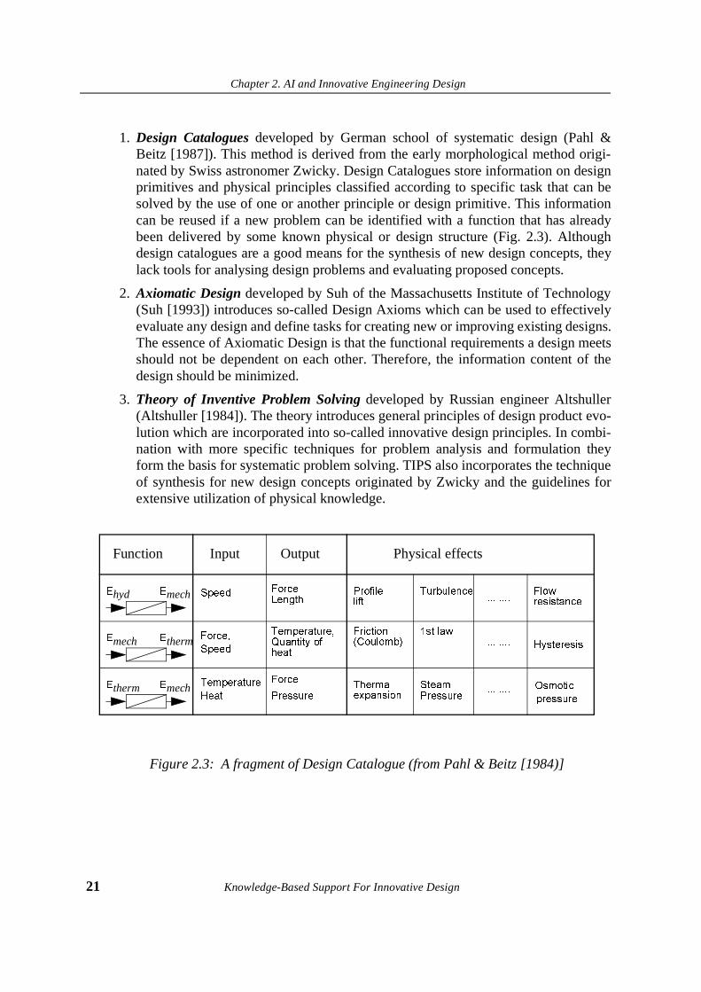
1. Design Catalogues developed by German school of systematic design (Pahl &Beitz [1987]). This method is derived from the early morphological method origi-nated by Swiss astronomer Zwicky. Design Catalogues store information on designprimitives and physical principles classified according to specific task that can besolved by the use of one or another principle or design primitive. This informationcan be reused if a new problem can be identified with a function that has alreadybeen delivered by some known physical or design structure (Fig. 2.3). Althoughdesign catalogues are a good means for the synthesis of new design concepts, theylack tools for analysing design problems and evaluating proposed concepts.
2. Axiomatic Design developed by Suh of the Massachusetts Institute of Technology(Suh [1993]) introduces so-called Design Axioms which can be used to effectivelyevaluate any design and define tasks for creating new or improving existing designs.The essence of Axiomatic Design is that the functional requirements a design meetsshould not be dependent on each other. Therefore, the information content of thedesign should be minimized.
3. Theory of Inventive Problem Solving developed by Russian engineer Altshuller(Altshuller [1984]). The theory introduces general principles of design product evo-lution which are incorporated into so-called innovative design principles. In combi-nation with more specific techniques for problem analysis and formulation theyform the basis for systematic problem solving. TIPS also incorporates the techniqueof synthesis for new design concepts originated by Zwicky and the guidelines forextensive utilization of physical knowledge.
Figure 2.3: A fragment of Design Catalogue (from Pahl & Beitz [1984)]
Function Input Output Physical effects
6SHHG
)RUFH��
6SHHG
7HPSHUDWXUH
+HDW
)RUFH/HQJWK
7HPSHUDWXUH�4XDQWLW\�RIKHDW
)RUFH
3UHVVXUH
(hyd
(mech�
(therm�
(mech�
(therm�
(mech�
3URILOHOLIW
)ULFWLRQ�&RXORPE��
7KHUPDOH[SDQVLRQ�
7XUEXOHQFH�
�VW�ODZ
6WHDP3UHVVXUH�
��������
��������
��������
)ORZUHVLVWDQFH�
+\VWHUHVLV�
2VPRWLF
SUHVVXUH�

Chapter 2. AI and Innovative Engineering Design
Knowledge-Based Support For Innovative Design 22
The three design methodologies mentioned above can be regarded as complementary and,when combined together, they form a general methodology for design based on an analysis -synthesis - evaluation cycle. (Figure 2.4).
Figure 2.4: Phases of conceptual design with relevant methodological support
In our research, we build a computational model of innovative design which incorporates thebasic principles of systematic methods. We have chosen the systematic approach due to twofactors:
• this is the only approach which is well understood, and
• it does not depend on the personal abilities of a designer.
In this book, we will label the conceptual phase of design organized in a systematic way asinnovative rather than creative. This difference is important since we do not establish ourgoal as modeling the cognitive process of creativity. Instead, we aim at developing a formalbackground which will result in the possibility of systematically creating the same productsthat could have resulted from creative thinking process. Further in the thesis, we will identifyinnovative design with non-routine and conceptual designs in order to avoid misunderstand-ings occurring within the literature on both engineering design and AI.
Analysis Synthesis Evaluation
conceptual design
Theory of InventiveProblem Solving
Systematic Design
AxiomaticDesign
Chapter 2. AI and Innovative Engineering Design
23 Knowledge-Based Support For Innovative Design
2.4. AI and innovative engineering design: related research
2.4.1 Role of AI for Design
While in the previous section we defined what is meant by conceptual engineering design, inthis section we will discuss what AI methods are available and how they are used to buildknowledge-based systems aimed at the generation of innovative design solutions.
The goal of AI can be defined as building sophisticated, machine-intelligent tools that arecapable of performing various types of activities which may only be accomplished under thecontrol of the flexible intelligence of human beings. Modern AI covers different topics ofvarious degrees of complexity from programs for playing chess to intelligent robots. Withrespect to design in general, we may also distinguish several different directions where dif-ferent AI methods and techniques are used. A classical approach within AI states that thedesign might be modelled as a problem solving process which can be organized as a searchwithin the predefined space of known solutions. The decision of which search space has to beexplored is made by the type of initial specifications and constraints given. The more preciseand detailed the specifications and constraints are, the smaller is the design search spacerequired to find a solution. Alternatively, when none of previous solutions can meet therequirements given, it is obvious that a search within a larger space is needed. In this situa-tion, two fundamental questions rise: what shall be an extension of the existing space? andhow to organize an effective search within the large design space?
One of the important issues which is frequently being discussed during meetings within theAI in Design community is: should an AI system for making new designs be based on exist-ing design theories and methods? Or, should the generation of new design concepts be basedon known AI methods, like genetic programming or analogical reasoning. This especiallyapplies to the earlier design phases, when the concept of a design is unknown and thereforecan not be found within predefined search space. The question mostly addresses philosophy,since even an ordinary process of creative design which is not supported by intelligent toolscan be either based on design methods such as the Theory of Inventive Problem Solving or itcan also be conducted in an unorganized manner, for instance, based on associative thinkingor brainstorming. An alternative concept regarding all phases of design as a scientific cate-gory is presented in detail in Alberts [1991]. The choice of an appropriate tool depends ofmany factors, whereas the most influential ones are consistency, the availability of solutionsand effectiveness.
2.4.2 Knowledge Categories in Design
Logan and Smithers distinguish between two types of knowledge required to organizeknowledge-based support for innovative design: domain knowledge and design knowledge(Logan and Smithers [1993]). Domain knowledge expresses facts about design objects, theirproperties and physical relations underlying the design objects. This knowledge is invariantacross designs within a domain (Clibbon & Edmonds [1995]) and forms a so-called design

Chapter 2. AI and Innovative Engineering Design
Knowledge-Based Support For Innovative Design 24
space. Design knowledge, in turn, specifies how the design space can be explored and trans-formed. In other words, it defines a strategy of how to identify problems and how to solvethem.
Another important note is that the role of both experiential and deep knowledge is crucial forinnovative design. From our point of view, both types of knowledge are complementaryrather than contradictory: using past experience helps to identify problems, the use of deepknowledge helps to synthesise new solutions.
Another important issue is that innovative design as opposed to routine design can not beorganized within a single engineering domain. Although new solutions can be obtained bysynthesising and instantiating “first principles” derived for each specific domain, their usagestrongly restricts the space of possible solutions. It happens since historically, engineeringhas been divided into many divisions, like electrical engineering, mechanical engineering,optics. As a result, the boundaries between domains and different physical principles thedomains based upon restrict knowledge transfer and adaptation from one domain to another.
In our project, we introduce a domain-independent approach to innovative design. To reachthis goal we investigate how both design and domain knowledge can be represented in a for-mal and uniform way to enable domain-independency and sharability of both design anddomain knowledge.
2.4.3 Models of Conceptual Design
Observing previous works in the AI in Design discipline, it is not difficult to draw the con-clusion that AI in Design is a mixture of various scientific and engineering methodologies.As a consequence, it might be the case that the same knowledge concept can be called “the-ory” in one paper and “model” in another. To avoid this and to bring clarity into further dis-cussion, we would like to define more clearly what is meant by theories, models andmethods. There is an approach introducing these definitions and distinctions presented inSmithers [1996]:
1. Theory is understood as statements about a particular phenomenon which make noreference to and do not depend upon particular instances of the phenomenon.
2. Model is an interpretation of a particular phenomenon which refers to instances orclasses of instances of the phenomenon which implies boundary conditions and con-straints. Models can be built using empirical knowledge and understanding. There-fore, models are possible without theoretical understanding.
3. Methods specify actions for a particular kind of designing. They are usually derivedfrom models. However, as opposite to models, if a method does not refer to a theoryor a model, it is impossible to estimate its consistency.
Further, we will also discuss which AI techniques are used today to model the process ofconceptual design and build intelligent tools based on these models.

Chapter 2. AI and Innovative Engineering Design
25 Knowledge-Based Support For Innovative Design
From an AI point of view, engineering design can be regarded as a procedure of mapping therequired specifications onto a description of physically realisable artifact (Tong and Sriram[1992]). A resulting design description has to be correct both in static and dynamic senses,that is, apart from an assembly of physical components, the device should possess the correctbehaviour.
Maher distinguishes between three phases which any model of overall design process has tobe comprised of (Maher [1990]):
1. Formulation: identification and specification of the requirements.
2. Synthesis: generation of design alternatives and constraints refinement and justifica-tion.
3. Evaluation: analysis and evaluation of generated design alternatives according topredefined criteria and given requirements.
The choice of a phase of design also brings substantial differences to models of design.When a routine design requires high computational complexity related to data transformationand implemented logical mechanisms, non-routine design relies heavily on reasoning withheuristic knowledge and operates within an ill-defined problem space. The degree of compu-tational complexity grows when a theory which can define a problem solving methodology isunavailable.
The main difficulty with building knowledge-based systems for innovative design - the lackof missing knowledge - is mentioned in Tong & Sriram [1992]: “the missing knowledgemight either be knowledge for directly generating new points in design space, or knowledgefor directly controlling the design space search”. Two reasons why relevant design knowl-edge can be missing are mentioned:
1. Most naturally acquirable knowledge might not necessarily be in a directly applica-ble form. If a designer wants to create a new coffee maker, he can scan various engi-neering literature and interpret the ideas proposed there with respect to the coffeemaker. However, these ideas might have nothing to do with coffee maker design.
2. It is impossible to store the large amount of knowledge that would be necessary toadequately deal with all possible design variations. Presenting various designs atdetail level would produce an enormous amount of information even within a singleengineering domain.
There is another, very important reason why the same knowledge is difficult to directly reuseat innovative phases of design. The same knowledge might have different interpretationsfrom different views, and it is impossible to predict and model all possible views. Forinstance, from the view of the transport domain, an air cushion can be interpreted as a way ofmoving objects; but in microelectronics it can be used to prevent two objects from contact-ing.
Chapter 2. AI and Innovative Engineering Design
Knowledge-Based Support For Innovative Design 26
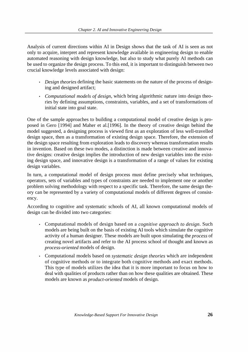
Analysis of current directions within AI in Design shows that the task of AI is seen as notonly to acquire, interpret and represent knowledge available in engineering design to enableautomated reasoning with design knowledge, but also to study what purely AI methods canbe used to organize the design process. To this end, it is important to distinguish between twocrucial knowledge levels associated with design:
• Design theories defining the basic statements on the nature of the process of design-ing and designed artifact;
• Computational models of design, which bring algorithmic nature into design theo-ries by defining assumptions, constraints, variables, and a set of transformations ofinitial state into goal state.
One of the sample approaches to building a computational model of creative design is pro-posed in Gero [1994] and Maher et al.[1996]. In the theory of creative design behind themodel suggested, a designing process is viewed first as an exploration of less well-travelleddesign space, then as a transformation of existing design space. Therefore, the extension ofthe design space resulting from exploration leads to discovery whereas transformation resultsin invention. Based on these two modes, a distinction is made between creative and innova-tive designs: creative design implies the introduction of new design variables into the exist-ing design space, and innovative design is a transformation of a range of values for existingdesign variables.
In turn, a computational model of design process must define precisely what techniques,operators, sets of variables and types of constraints are needed to implement one or anotherproblem solving methodology with respect to a specific task. Therefore, the same design the-ory can be represented by a variety of computational models of different degrees of consist-ency.
According to cognitive and systematic schools of AI, all known computational models ofdesign can be divided into two categories:
• Computational models of design based on a cognitive approach to design. Suchmodels are being built on the basis of existing AI tools which simulate the cognitiveactivity of a human designer. These models are built upon simulating the process ofcreating novel artifacts and refer to the AI process school of thought and known asprocess-oriented models of design.
• Computational models based on systematic design theories which are independentof cognitive methods or to integrate both cognitive methods and exact methods.This type of models utilizes the idea that it is more important to focus on how todeal with qualities of products rather than on how these qualities are obtained. Thesemodels are known as product-oriented models of design.
Chapter 2. AI and Innovative Engineering Design
27 Knowledge-Based Support For Innovative Design
The advantage of product-oriented design models over process-oriented ones is that they canbe checked against physical reality while the others are rather subjective. Nevertheless, it isnot possible to model only a process or a product since there might be neither a process with-out a product nor vice versa. For instance, if a design theory of how to generate new designsolutions from physical principles is available, then the theory of how to search for newproblems is not known yet. To solve this problem, a cognitive technique, for instance, rea-soning by analogy might be integrated with a model built upon reasoning from physical prin-ciples. However, availability of results depends on what general reasoning strategy has beenchosen. For this reason, we argue that a product-oriented model of design which, of coursemight incorporate some process-oriented mechanisms, is preferable.
2.4.4 Models of Design Based on Cognitive Methods
One of the first AI methodologies successfully transferred into industry was a problem solv-ing technique for heuristic search based on logical reasoning. The famous system DAAdates back to 1985 (Kowalksi [1985]). However the idea of modeling the expert knowledgeand reasoning process performed by an inventor failed since the resulting expert systems arevery hard to modify when new knowledge emerges. Besides, the framework expert systemsare built upon is limited to representing the knowledge of narrow domain. However, as wenoted in previous sections, the main distinction between routine and non-routine designs isthe degree of utilization of principles behind the specific domain.
Another widespread AI technique for design problem solving is Case-Based Reasoning(CBR) (Kolodner [1991], Wills & Kolodner [1994]), which utilizes the idea of the reuse ofprevious experience. In contrast to traditional expert systems, a CBR system is possible tomodify when new knowledge and requirements emerge. The essence of CBR is that it real-ises a model of reasoning by reusing previous knowledge represented in the form of cases.With CBR, no design theory is needed. CBR organizes the process of innovative design in amanner most human designers do: conscious or unconscious search of their memory for pre-vious problems and solutions that are similar to a given design problem. Computer imple-mentation of CBR consists in a case repository storing previous design cases indexedaccording to problem specifications. The search for a new solution starts with the identifica-tion of what indices of a given problem are identical to the stored ones. Examples of AI sys-tems built on CBR are CADET (Navinchandra [1991]), in which a behavioural description iselaborated to have new indices so that various parts of the behaviour can be identified andCADSYN (Maher et al. [1993]) which decomposes cases into subsystems when no matchingcase is found. If the solution retrieved does not meet all the requirements given, a case adap-tation has to be performed. However, there might be a case when domain knowledge is notenough for meaningful adaptation. As a result, CBR works well whilst no significant adapta-tion is needed. Therefore, CBR is highly applicable to routine design tasks and less or evennon-applicable to solving non-routine design tasks unless a technique for conceptual adapta-tion is known. Although the CBR method is, perhaps the best way available to collect, indexand retrieve previous experiential knowledge, for innovative design problems the task of

Chapter 2. AI and Innovative Engineering Design
Knowledge-Based Support For Innovative Design 28
conceptual adaptation is more difficult and has much higher complexity than the search for asimilar case.
Attempts to overcome the limitations of CBR are made by trying to organize design based onreasoning by analogy. An analogy in AI is defined as the product of cognitive process whichestablishes mappings between causal structures of different domains (Keane [1988], Wolver-ton & Hayes-Roth [1995]). In the approach to design exploration using analogy (Qian &Gero [1996]), it is claimed that in contrast to the literal similarity that is used in CBR, the useof analogy makes it possible to map relational structures and, especially, higher-order rela-tions underlying qualitative casual relations. The disadvantage of using reasoning by analogyis similar to one of CBR: although reasoning about more deep knowledge is possible andmore creative solutions can be generated, the lack of a general strategy for limiting the searchfor a solution appears to be very crucial for this method. Another problem appears when wetry to represent knowledge of different domains to organize analogical reasoning: it isunclear in what form all the relations are to be presented and there is no guarantee that somevery important chunks of this knowledge will be neglected.
Another rapidly progressing modern approach to designing novel artifacts is based ongenetic programming. Genetic programming is an analog of the naturally-occurring evolu-tionary process (Holland [1975]). The genetic programming can be applied to solve variousscientific and engineering problems. With respect to design tasks, for instance, in DARWIN(Kruiskamp & Leenaerts [1995]), new topologies of operational amplifiers are designed onthe basis of the evolution of an initial population of hand-designed topologies through theoperations of crossover and mutation. The fitness of each amplifier is computed using a devi-ation between the actual behaviour of a circuit and the desired behaviour. Although geneticprogramming is a promising technique, it is solely based on a predefined set of solutionsdrawn from a specific engineering domain. As a consequence, the resulting population incor-porates the same fundamental principles of the specific domain which the initial populationis based upon. To be able to draw and utilize different principles, a system based on a geneticalgorithm should have unlimited power and capacity, since successful fundamental muta-tions take very long time as occurs in nature.
The general disadvantage of the above mentioned AI techniques is that while a limited set ofinnovative design solutions within known design space is possible to generate, the solutionsbased on principles unknown in this particular engineering domain might not be found. Tosolve this problem, better understanding of the nature of the innovative design process isneeded. The goal of understanding the nature of innovative design is twofold: first we wantto know if general principles behind the innovative design process exist and, if they do, howto apply the principles to generate new design solutions.
2.4.5 Models of Design Based on Design Theories
In Smithers [1996], a dramatic trend within the AI in Design community is outlined: “a sur-vey of AI in Design research shows not just a lack of development of usable theory (or theo-

Chapter 2. AI and Innovative Engineering Design
29 Knowledge-Based Support For Innovative Design
ries) of design process, it also demonstrates widespread ignorance and neglect of related andrelevant work on the fundamental nature of design process by researchers in the DesignResearch Community” . This is a very important issue, and it addresses not only the questionof the place of design theories in AI. The best design theory, by definition, is the theorywhich is based on a set of axioms that would make it independent of the cognitive abilities ofa human designer. Examples of systems built upon CBR or genetic programming show that,without such a theory, the size of the knowledge base must be enormous in order to incorpo-rate all existing designs; the reasoning methods available are not effective enough to generatethe expected solutions, and there is no guarantee that the feasible solution(s) will be found atall.
As follows from the analysis of failures of using pure AI techniques to build AID systems forsolving non-routine design tasks, it becomes obvious that there are two main problems to betackled:
1. How to model and represent the existing design knowledge of many domains tomake it available at different steps of domain-independent reasoning process.
2. What reasoning strategy should be used to support reasoning with this knowledgeto generate and evaluate innovative design solutions in different domains.
In order to answer these questions, many research efforts have been undertaken lately. First,it is clear that it would not be possible to model and represent all available design knowledgein a uniform way and independently of a particular task. Therefore, there is the need to selectwhat knowledge categories are to be chosen and how they fit the general reasoning method-ology. Second, the reasoning strategy must be able to deal with ill-defined problem formula-tions and less travelled design search space.
One of the solutions to the problem of dealing with high complexity of engineering knowl-edge is seen as abstracting from specific engineering data to the level of physical knowledge.Any engineering system can be modelled as a set of physical phenomena occurring withinthe system and interacting with each other. Therefore, the most difficult part of the reasoningprocess concerning innovative modification of the system can be performed using abstractknowledge. Apart from that, the advantage of such a modeling framework is that physicalprinciples can be organized and accessed in a systematic way while it is unclear how toaccess detailed engineering knowledge, especially when cross-domain search is involved.From this point of view, a conceptual engineering design can be modelled as a two-levelknowledge translation process: first, finding what physical principle(s) best matches therequirements and constraints given, then - instantiation of the selected principle(s) into spe-cific design description. The reasoning strategy should be based on systematic search andevaluation of the solutions.
Attempts to build a theory of reasoning with abstract physical knowledge, but to prevent thisknowledge from possible incorrect interpretation led to appearance of naive physics (Forbus[1984], Akman & ten Hagen [1989]). The basic assumption behind this approach is that the
Chapter 2. AI and Innovative Engineering Design
Knowledge-Based Support For Innovative Design 30
highly complicated world of physical systems should be regarded from of viewpoint of whatthe qualities of the systems are, rather than what their quantities are. The dynamic aspects ofa system’s behaviour are expressed through so-called qualitative simulation based on quali-tative approximation of differential equations constituting relations between system parame-ters. An example of integration of qualitative reasoning and Case-Based Reasoning is shownin Sycara & Navinchandra [1989]. However, modeling the qualitative behaviour of physicalsystems seems to be more suited for tasks of explanation and generation within AI whereasquantitative models are more applicable for mathematical simulation. This is an argumentwhich is difficult to discuss unless AI systems for innovative design synthesis based on theconcepts of naive physics are available and, therefore, might be studied, compared and eval-uated. However, naive physics has given impact to modeling physical knowledge for severalAI in Design applications which will be discussed below.
One of the well-known models of innovative design based on the utilization of physicalknowledge is designing from first principles proposed by Williams [1990]. This approach isbased on the assumption that engineering devices are constructed by focusing on qualitativedifferences between how alternative devices work. The design process is represented as rea-soning from first principles. It is also assumed that every specific domain has its own set offirst principles, and new devices topologies can be composed by generating new behavioursby imagining all possible interactions produced by components and connections. The basiclimitation of this approach is that it regards innovative design as a modification of designspace based on transformations which are allowed by the principles previously incorporatedin a particular engineering domain. As a consequence, utilization of the principles of otherdomains does not seem to be possible.
More recent research efforts have concentrated on tackling this dilemma by extending theparadigm of designing from first principles to designing from physical principles. In Tauraet al. [1994], a framework for constructing the natural law database is presented which stud-ies the method for representing physical knowledge based on object-oriented paradigm. Thegoal of creating the database is to establish a relation between past technological inventionsand the physical principles the inventions are based upon. Nevertheless, the selected mode-ling framework does not enable the automatic synthesis of new design concepts although itmight be useful for assisting purposes.
A further extension of the paradigm of designing from physical knowledge is designing fromgeneric knowledge. One of the first design-oriented AI systems based on the reasoning fromgeneric knowledge was EDISON (Dyer et al. [1986]). The system was intended for the gen-eration of novel mechanical devices and consisted of so-called conceptual primitives repre-senting models of physical phenomena. However, these primitives were rather intuitive.
To enable cross-domain reasoning, all available physical laws and phenomena are to be mod-elled in a way which would make it possible to combine the principles selected from differ-ent physical domains without violating the law of energy preservation. As a fundamentalbackground allowing for such modelling, a theory of Bond Graphs (Karnopp et al. [1990]) isused. The Bond Graphs theory was derived from more general System Theory (Shearer et

Chapter 2. AI and Innovative Engineering Design
31 Knowledge-Based Support For Innovative Design
al.[1969]) and regards the world of physical phenomena as a set of operations on energytransformations and storage. This makes it possible to represent various physical effects in auniform way. Once a particular physical phenomenon is described as a specific transforma-tion of the energy flow of a certain type, it can be connected to another phenomena which isable to deal with the same type of the energy flow (Zaripov [1988]). The material informa-tion is not included in Bond Graphs structures.
To enable mappings between real word problems and predefined models of physical effects,a problem given is identified with a physical function which is to be delivered by a resultingconcept as well as with a set of constraints indicating physical limitations. The goal functionof the device and intermediate functions defining connectivity of physical phenomena aremodelled in terms of elementary energy transformations. Applying the law of energy preser-vation, it is possible to synthesise a physical structure containing a set of effects linkedtogether which would deliver the required function.
An example of the research using Bond Graphs theory as a modelling framework is shown inMalmqvist [1993]. The system for automated generation of design alternatives discussed inthis work is based on Hubka’s theory of engineering design (Hubka & Eder [1988]) whichregards machines as transformation systems. Given a physical function, it is possible to syn-thesise several alternative bond graphs of the process structure which can later be translatedinto detailed design description.
The principal disadvantage of modeling frameworks which use Bond Graphs is that they arelimited to modeling energy-transforming systems. For this reason, information and materialtransformations can only modelled if they are carried by an energy flow. As a consequence, alarge number of innovative problems dealing with material transformations may not be sup-ported by the Bond Graphs approach unless these transformations are not represented interms of energy transformations. Another problem has to do with the evaluation of generateddesign alternatives: due to a lack of material information, it is impossible to evaluate thequality of the solutions at the phase of concept generation with respect to material implemen-tations.
An attempt to tackle the above mentioned disadvantages was undertaken in building Knowl-edge Intensive Engineering Framework (KIEF) (Ishi et al. [1993], [1995]) which enablesdesigners to synthetically build models of mechanisms with a description of physical lawsthat are essential components to compose design object models. Early versions of KIEFincluded a knowledge base of physical phenomena modelled on the basis of the QualitativeProcess Theory. However, to eliminate the limitations of qualitative modeling, KIEF wasextended with external design object models such as Bond Graph models and models forprocessing quantitative information.
Another approach worth mentioning is based on a combination of product-based designderived from the German school for systematic design and Suh’s General Principles ofDesign which provides guidelines for improving design process (Schmekel [1992]). TheGeneral Principles of Design are formulated on the basis of the so-called The Independence

Chapter 2. AI and Innovative Engineering Design
Knowledge-Based Support For Innovative Design 32
Axiom which states that “a design which maintains the independence of functional require-ments is better than a design which does not” (Suh [1993]). Therefore, by analysing whatparameters of the existing design negatively influence each other, it is possible to evaluatewhat design has a lower information content or what parameters have to be decoupled toachieve the better design. However, implementation of this methodology can probably givebest results at the phase of evaluation of design alternatives when tools specifying how thefunctional requirements can be decoupled are not available.
Recently, the ontological approach has gained popularity for developing modeling frame-works. (Gruber [1993]). An ontology enables one to make commitments about various typesof knowledge, represent knowledge in a uniform way and make the knowledge sharablebetween various application domains. As a consequence, knowledge represented within oneontology can easily communicate with knowledge of another ontology after having agreedon ontological commitments. This point is crucial for innovative design since it deals withvery different types of knowledge. Another aspect sharability of knowledge plays anincreasingly important role in establishing a reasoning process when the same knowledge hasto be shared between different domains.
Among recent examples of building ontologies that would be applicable to engineeringdesign are MathEng (Gruber & Olsen [1994], an ontology for representing mathematicalinformation about technical systems, SHADE (McGuire [1993]) which enables knowledgesharability for collaborative engineering, and PhysSys ontology for physical systems (Borstet al. [1995]), to name a few.
An example of an ontology which introduces a framework for modeling both domain anddesign knowledge is YMIR (Alberts [1993]). YMIR is based on a formal approach to designdrawn from System Theory and captures many advanced techniques for knowledge model-ling and reasoning. As opposed to systems which produce recommendations in terms of gen-eral physical principles or ready-to-use specific design descriptions, YMIR has the ability tointroduce intermediate levels of abstraction between a generic design principle based on acertain physical phenomenon and the design instances of this principle. To instantiategeneric knowledge into design descriptions, a set of ontological concepts and reasoning strat-egy were developed to enable automated translation between levels. Since, as a modellingframework YMIR is the best suited to the goals of this thesis, it will be discussed in moredetails in Chapter 4.
A proof that innovative design can be very effectively organized in a systematic manner wasdeveloped in the Russian school of inventive design. Several computer systems were built onthe basis of the Theory of Inventive Problem Solving, among them are INVENTIONMACHINE (Tsourikov [1993]), EDISON (Glasunov [1993]). In reality, these systems arestill far beyond the utilization of AI methods for representing knowledge and automated rea-soning. However, the theoretical background behind these systems is based on integration ofdesigning from physical principles and methods for engineering conflict elimination whichprovide guidelines for clearing specifications. Therefore, a procedure for the generation of
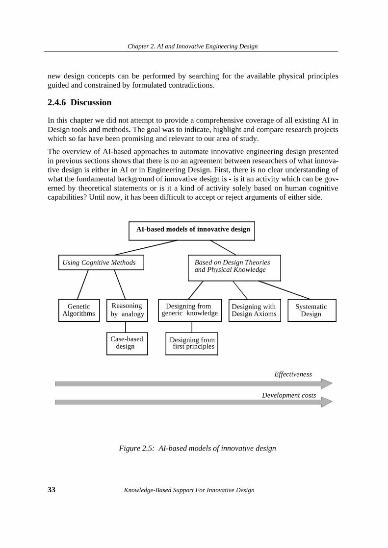
Chapter 2. AI and Innovative Engineering Design
33 Knowledge-Based Support For Innovative Design
new design concepts can be performed by searching for the available physical principlesguided and constrained by formulated contradictions.
2.4.6 Discussion
In this chapter we did not attempt to provide a comprehensive coverage of all existing AI inDesign tools and methods. The goal was to indicate, highlight and compare research projectswhich so far have been promising and relevant to our area of study.
The overview of AI-based approaches to automate innovative engineering design presentedin previous sections shows that there is no an agreement between researchers of what innova-tive design is either in AI or in Engineering Design. First, there is no clear understanding ofwhat the fundamental background of innovative design is - is it an activity which can be gov-erned by theoretical statements or is it a kind of activity solely based on human cognitivecapabilities? Until now, it has been difficult to accept or reject arguments of either side.
Figure 2.5: AI-based models of innovative design
Using Cognitive Methods Based on Design Theories
Reasoning analogy
Case-baseddesign
GeneticAlgorithms
Designing fromfirst principles
Designing fromgeneric
Designing withDesign Axioms
AI-based models of innovative design
knowledgebySystematic
Design
Effectiveness
and Physical Knowledge
Development costs

Chapter 2. AI and Innovative Engineering Design
Knowledge-Based Support For Innovative Design 34
Sometimes, the argument rises that conceptual design can not be modelled as a search proc-ess. The reason is that an output of conceptual design is new knowledge that has not beenknown before and, therefore, may not be found among available solutions.
From our point of view, innovative design can be organized as a search process, since theresulting knowledge is actually not a new knowledge regarded at the high level of generaliza-tion. A new design product description is an instance of some known fundamental knowl-edge after a novel interpretation of this fundamental knowledge in terms of a specificsituation has been made. We argue, that the search might be organized at the level of funda-mental knowledge and new design concepts can be represented in terms of fundamentalphysical knowledge.
Figure 2.5 presents a classification tree of models of innovative design based on the existingmainstream within AI in Design research according to their efficiency. The efficiency rate isan integrated factor which comprises such characteristics of models as the size of searchspace, applicability in different domains, availability of solutions, quality of solutions gener-ated, and a capability to evaluate solutions.
As seen from the picture, the most promising are models built upon general theories ofdesign. To be successfully implemented as computer tools they must be able to deal with var-ious types of knowledge representation and reasoning methods. This, however, causesgrowth of development costs.
Another important conclusion is that any computational model of innovative designs wouldinvolve reasoning about a large diversity of knowledge. This knowledge can be of variousdegree of abstraction: it might be facts on physical properties of specific materials as well asgeneral principles for design. To be successfully applied, it should be represented in a shara-ble way. As a possible means to achieve the sharability, we use an ontological approach tomodeling knowledge.
Chapter 3. The Theory of Inventive Problem Solving
35 Knowledge-Based Support For Innovative Design
Chapter 3. The Theory of Inventive Problem Solving
“I invent nothing. I rediscover”.
Auguste Rodin (1840-1917)
“Keep on the lookout for novel ideas that others have usedsuccessfully. Your idea has to be original only in its adaptation to the
problem you’re working on”.
Tomas Edison (1847-1931)
3.1. Introduction
Until now, designers and engineers did not have access to a systematic approach to solvingproblems arising in the predevelopment phase of design. As a consequence, a lack of generalmethodology for solving inventive problems in a systematic way did not allow computer sci-entists to develop a computable model that could be implemented as a computer program.
Chapter 3. The Theory of Inventive Problem Solving
Knowledge-Based Support For Innovative Design 36
The previously little known, the Theory of Inventive Problem Solving (TRIZ1) originated byRussian engineer and scientist Genrich Altshuller proved that a systematic approach to theinventive process is possible. A major conclusion of Altshuller’s studies was that inventionswere not a result of unorganized thinking, but instead the products of objective laws andtrends of technology evolution. However, these laws have been unconsciously utilized byinventors. TRIZ made these trends explicit.
Comprehensive studies of the patent collections2 following this discovery resulted in twomore findings. First, Altshuller shows that an inventive solution results from elimination of acontradiction which is caused by attempts to improve preceding design products (Altshuller[1956]). Attempts to compromise without eliminating the contradiction do not allow adesigner to achieve the desired degree of improvement. The second conclusion is that themajority of the patented inventions complies with a relatively small set of basic principles foreliminating the contradictions.
Based on these findings, Altshuller and his research associates have developed a scientifi-cally-based problem solving methodology which codifies numerous inventive principles andincorporates the laws of engineering system evolution (Altshuller [1984], Arciszewski[1988], Fey et al. [1994], Linde et al. [1994], Sushkov et al. [1995]).
Assuming that there is a lack of literature available in English that presents TRIZ from a sci-entific point of view, we decided to briefly discuss the major aspects of TRIZ fundamentalsand problem-solving techniques in the book3.
This chapter is divided into three parts. First, we present TRIZ historical background andphilosophy. Second, TRIZ problem solving techniques based on a systematic approach toinventive design are discussed. To provide better understanding of TRIZ concepts, they areillustrated by examples of inventive solutions drawn from different engineering domains. Inthe last part, we present ARIZ, an integrated problem-solving technique which aims at solv-ing the most difficult inventive problems.
We should however note, that our presentation of TRIZ slightly differs from TRIZ presentedin Altshuller [1984] due to two factors: i) a direct translation of TRIZ terms into Englishmade in the book appeared to be misleading and we had to improve translations; and ii) ourstudy resulted in a restructuring of some TRIZ parts, namely, the theory of technology evolu-tion.
1. There are two abbreviations available in the literature on the Theory of Inventive Problem Solving: TRIZ (English abbre-viation) and TIPS (Russian abbreviation). There is still no common agreement what abbreviation to use. To avoid confu-sion, we will further use the abbreviation TRIZ since it is more widely used.
2. It is claimed that over 40 years TRIZ researchers studied more than 1.500.000 patent descriptions drawn from different areas of technology.
3. Recently, there has been much discussion about what TRIZ is between various schools of design. Definitely, TRIZ is not an exact theory from a scientific point of view, since most of TRIZ conclusions were obtained by abduction. We would prefer to label TRIZ collections of problem solving techniques as a set of recommended practises based on empirical rules of design. However, to avoid confusion with existing literature, we will use the abbreviation TRIZ throughout the book.
Chapter 3. The Theory of Inventive Problem Solving
37 Knowledge-Based Support For Innovative Design
3.2. TRIZ contents
In this section, we present a brief overview of TRIZ historical background, TRIZ philosophyand the structure of modern TRIZ.
3.2.1 Historical background
TRIZ was originated by Altshuller in 1946. The first problem solving technique labelledinventive principles resulted from studying more than 40.000 patent descriptions. It indicateswhat general principles are applicable to solving various types of contradictions occurring indifferent engineering domains. Currently, the collection consists of 40 inventive principles.
Further, TRIZ evolution resulted in the creation of a more precise technique for inventiveproblem solving - a collection of Inventive Standards, also known as the rules for substance-field modification. An Inventive Standard enables a designer to represent a part of a productwhere a problem occurs in terms of the specific components the design product consists ofand modify the product.
The third TRIZ major component is Pointer to physical, chemical and geometrical effects.They provide a mapping between a specific function a new design product has to deliver anddescriptions of physical, chemical and geometrical phenomena that are capable of deliveringthe required function.
Every TRIZ problem solving technique can be used independently. All three problem solv-ing techniques are presented in section 3.4.
Further studies of patent collections revealed the trends of technology evolution (section 3.3)which form a theoretical background of modern TRIZ.
Apart from specific problem-solving techniques, Altshuller developed an integrated frame-work which enables consistent use of different TRIZ problem solving techniques. The frame-work was labelled Algorithm for Inventive Problem Solving (ARIZ)1. The first version ofARIZ was developed in 1961 (Altshuller [1969]). Since, the ARIZ has been largely extendedand modified. The latest Altshuller version of ARIZ2 is ARIZ-85B. ARIZ-85B is presentedin detail in section 3.5.
Lately, TRIZ has proven itself as a very strong tool to solve inventive problems and inventnew products. In 1984, about 300 TRIZ research and training centres existed in the USSR. Inthe end of nineties, TRIZ became known outside Russia and the former Soviet states.
Today, TRIZ continues to develop and there are also attempts to integrate TRIZ with othermethods for design. For instance, one research direction investigates the applicability ofTRIZ for supporting Suh’s General Principles of Design (Nordlund [1994]). Another direc-
1. Similarly to TRIZ, ARIZ is also known as AIPS.
2. Other versions of ARIZ developed by different authors are also known. However, it is the professional judgment of the authors that ARIZ-85B is the most consistent version of the algorithm.
Chapter 3. The Theory of Inventive Problem Solving
Knowledge-Based Support For Innovative Design 38
tion studies how TRIZ can be combined with other methods for product conception, such asQuality Function Deployment (Verduyn & Wu [1995]).
3.2.2 Levels of Inventive Solutions
To provide better understanding of the origin of inventions, Altshuller developed a new clas-sification of design solutions. He divided all technical solutions into five large groups. Thegroups differ in the way the solutions were obtained:
1. Routine Solution does not require that contradictions be solved, since the neededsolution can be found within the same engineering domain. Standard solution resultsfrom a redesign of some of the existing components of a system.
Example 3.1.
To enforce a building, its walls might be made more thick. �
2. Change of a System: pertains to more difficult problems which contain contradic-tions. A contradiction arises when mutually exclusive requirements should beplaced on the same system. However, the contradiction might be eliminated bymethods known within the discipline.
Example 3.2.
Foam instead of water can be used to intensify putting out fire. �
3. Innovation: a solution to a problem is outside of the engineering discipline, butavailable in another field of engineering. Innovation results in replacement of a sys-tem which causes the contradiction.
Example 3.3.
To measure a thickness of a thin conductive wire in microelectronics, it was proposed touse a known method in the wire manufacturing industry for measuring the diameter ofmicrowire using the physical effects of Corona discharge.�
4. Invention: the solution is not available within existing engineering fields, but it canbe found among physical or chemical phenomena. As a result of invention, a newtechnical system is synthesized.
Example 3.4.
Invention of a vehicle using air cushion.�
Chapter 3. The Theory of Inventive Problem Solving
39 Knowledge-Based Support For Innovative Design
5. Pioneering invention: the solution is based on recently discovered scientific phe-nomena. Pioneering inventions launch new engineering disciplines.
Example 3.5.
Invention of radio or photography.�
Using TRIZ, it is possible to successfully tackle engineering problems of the second, thirdand fourth groups: those problems which can not be solved without elimination of contradic-tions. Instead of a chaotic search for the solutions proposed by cognitive methods, such asbrainstorming or synectics, TRIZ organizes the search in a systematic way.
3.2.3 TRIZ Philosophy
More than 40 years of studying patents in different areas of engineering resulted in severalimportant discoveries which form the TRIZ philosophy:
1. Every engineering system evolves according to regularities which are general for allengineering domains. These regularities can be studied and used for innovative andinventive problem solving, as well as for forecasting the further evolution of anyengineering system in design terms.
2. Engineering systems, like social systems, evolve through the elimination of variouskinds of contradictions. The principles for eliminating the contradictions are univer-sal for all engineering domains.
3. An inventive problem can be represented as a contradiction between new require-ments and an engineering system which is no longer capable of meeting the require-ments. Finding an inventive solution to the problem means to eliminate thecontradiction under the condition that a compromise is not allowed.
4. Frequently, when searching for the inventive solution to a problem formulated as acontradiction, there is the need to use physical knowledge unknown to the domainengineer. To organize and direct the search for appropriate physical knowledge,pointers to physical phenomena should be used. In the pointers, the physical phe-nomena are structured according to technical functions that can be achieved on thebasis of the phenomena.
Classical TRIZ which will be discussed below consists of several problem modeling andproblem-solving techniques. It introduces a uniform way of modeling inventive problems byrepresenting them in terms of contradictions and generic principles for resolving the contra-dictions. A comprehensive study of patent collections undertaken by TRIZ researchers andthorough tests of TRIZ within industries have proven the fact that if a new problem is repre-sented in terms of a contradiction, then it can be solved by applying the relevant TRIZ princi-ple. The principle must indicate how to eliminate the same kind of contradiction encountered
Chapter 3. The Theory of Inventive Problem Solving
Knowledge-Based Support For Innovative Design 40
in some engineering domain before. However, the most important achievement in TRIZ hasbeen the formulation of general problem solving principles covering virtually all possibletypes of innovative and inventive problems.
3.2.4 TRIZ Structure
The structure of TRIZ is shown in Figure 3.1. It includes the following parts:
1. Laws of engineering system evolution. This part of TRIZ studies and formulatesgeneral trends of engineering system evolution.
2. Problem solving techniques. The techniques aim at building a problem model andproducing recommendations on how to solve the problem. Among them are:
2.1. Principles for the elimination of engineering conflicts;
2.2. Principles for substance-field modeling for solving inventive problemsthrough representing them in terms of substance-field interactions andapplying generic patterns of interaction transformations.
2.3. Pointers to scientific-engineering effects. This part of TRIZ focuses on stud-ying how to use the knowledge of exact sciences in the inventive process.
2.4. Algorithm of Inventive Problem Solving - an integrated technique aimed atsolving most difficult inventive problems.
3. Collections of advanced patents. This part contains patent descriptions drawnfrom various engineering domains. The patents are structured according to inventiveprinciples used to solve one or another type of contradictions. The patents can beused as analogous design cases illustrating the applicability of the principles andmaking a problem-solving process easier.
4. Functional and Value Analysis. It is a modified version of traditional Value-Engi-neering Analysis proposed by Miles [1972] with the focus on functional analysis oftechnical systems.

Chapter 3. The Theory of Inventive Problem Solving
41 Knowledge-Based Support For Innovative Design
Figure 3.6: Structure of the Theory of Inventive Problem Solving
3.2.5 Technical system
TRIZ operates with a number of concepts which are used for problem formulation and solv-ing. Since TRIZ was developed to support solving problems dealing with physical systems,its concepts can be regarded as generic with respect to any design product involving mate-rial-energy transformations.
To systematize knowledge about the inventive process, and to make reading the next sectionsmore clear, we should define the major TRIZ concepts:
Definition 3.1.
Technical system1: any artificially created system which consists of interactingmaterial components and energy flows. The technical system possesses a deter-ministic behaviour in order to deliver a given functionality. Any design productcan thus be regarded as a technical system if it involves transformations of mate-rials or energy flows no matter how many components are involved.
1. In some other publications on TRIZ, the term “engineering system” is used.
Theory of Inventive Problem Solving
Problem-solvingtechniques
Theory of Engineering
Principles for eliminationof engineering contradictions
Principles for substance-field modelling
Pointers to scientific-engineering effects
Algorithm of InventiveProblem Solving
System Evolution Functional Analysis
Trends of evolution
Physics
Chemistry
Geometry
Trimming techniques
Collections ofadvanced patents
Chapter 3. The Theory of Inventive Problem Solving
Knowledge-Based Support For Innovative Design 42
It is important to note that most of the concepts presented above are defined in TRIZ in aqualitative manner. In the next sections, the major TRIZ problem-solving techniques basedon these concepts are discussed in details.
3.3. Theory of Technical System Evolution
The theoretical background behind TRIZ is formed by the Theory of Technical System Evo-lution (TTSE). Our opinion is that an understanding of the systematic nature of technologyevolution is very important in building a computer support for design. Respectively, in thissection, we present trends of technology evolution as well as more specific evolution pat-terns. Since we do not aim at comprehensive coverage of TRIZ in the book, we will onlypresent the basic concepts.
3.3.1 Systematic nature of technology evolution
A long-term study of patent collections and hundreds of bibliographical sources presentingthe history of technological development resulted in the conclusion that the process of tech-nological evolution is not chaotic even if a designer is not aware of it. The development oftechnology correlates with the evolution of societal needs which, in turn, obey more generallaws of nature. Therefore, the process of evolution of technical systems can be studied toreveal what regularities underlie it.
A further research in TRIZ was aimed at revealing and studying basic laws and trends oftechnical system evolution (Altshuller [1984], Salamatov [1991]). The laws and the trendsindicate general regularities of evolution which can be applied to each branch situation.TTSE states that the evolution of any technical system obeys these regularities independentlyof the domain the system belongs to. As a consequence, the applicability of the laws andtrends is not restricted to a single domain, they are valid for the every engineering discipline.
In TRIZ literature, no separation is made between the laws and the trends. Nevertheless, bylooking at TTSE laws as proposed, for instance, in Salamatov [1991], it becomes obviousthat there is a clear distinction between:
• the laws of evolution which denote general conditions for the creation and develop-ment of technical systems.
• the trends of evolution which denote what particular phases of evolution a systempasses. However, not every system passes all phases of evolution indicated in thetrends - some of the phases could be missed. Therefore, it would not be correct torefer to them as to laws.

Chapter 3. The Theory of Inventive Problem Solving
43 Knowledge-Based Support For Innovative Design
3.3.2 The law of system ideality
The primary law of the theory of technical system evolution is the law of system ideality. Itstates that during evolution over the time, any system tends to increase a ratio between theoverall performance of the system and the expenditures necessary to provide the requiredperformance.
The law indicates a principal design requirement which every designer has to keep in mindwhile creating a new engineering system: a system being designed must be able to deliver thebest performance possible, whereas the expenditures required to provide the system life-cycle should be minimized. The expenditures in this definition are all types of energy, mate-rial and informational resources required to deliver the given functionality and meet all otherrequirements.
Formally, the end point of ideality growth for system Φ can be expressed as:
where I is a system ideality and E are the expenditures involved to achieve a system’s per-formance P In turn, two particular types of achieving the ideality are possible:
that is, expenditures decrease without performance change and
that can be interpreted as performance growth without increasing the expenditures.
Strictly speaking, an ideal system is a philosophical category since it may not exist. Never-theless, it is useful to use this notion in engineering just like it is used for modeling purposesin exact sciences. For instance, idealized models in physics or chemistry help to create anddescribe the existing and possible physical systems.
Example 3.6.
When developing a portable radio station for mountain-climbers the problem of ensuringtemperature stabilization of the oscillator’s quartz crystal arose. Instead of using a con-
I Φp E( )E 0→P ∞→
lim=
I1 Φp E( )E 0→P const=
lim=
I2 Φp E( )E const=P ∞→
lim=
Chapter 3. The Theory of Inventive Problem Solving
Knowledge-Based Support For Innovative Design 44
ventional thermostabilizer which is too heavy and needs a special power source, it wassuggested to fix the crystal on the mountain-climber’s body. Hence, the function of tem-perature stabilization is fulfilled with no special design at all.�
3.3.3 TTSE Laws
TTSE presents four laws of engineering systems evolution including the law of system ideal-ity growth. Other TTSE laws are:
1. Law of system completeness: any technical system must have a complete material-energy structure to deliver the required function.
2. Law of energy conductivity: a necessary condition of the functioning of any sys-tem is providing energy flows through all parts of the system.
3. Law of irregularity of system’s parts evolution: the more complex a systembecomes during the evolution the more irregularly its parts evolve. As a result, fur-ther development of the system becomes more difficult due to contradictions arisingbetween system’s parts.
3.3.4 TTSE Trends
If the laws denote primary conditions and observations for the creation and development ofany technical systems, the trends define how the system’s physical structure changes duringthe system’s evolution. They include generic patterns which present detailed information onthose changes. Among TTSE trends are:
1. Trend of increasing a number of material-energy interactions: any system tendsto increase the degree of interacting material-energy components to provide betterperformance and controllability.
2. Trend of frequency and form adjustment: during evolution, any system tends toadjust frequencies and forms of interacting components.
3. Trend of dynamics growth: any system tends to increase the degree of freedom ofits movable parts by transition to a more flexible physical structure.
4. Trend of transition to microsystem: any system tends to replace a physical princi-ple behind its components delivering main function with a new physical principleutilizing properties of more fragmented materials, microparticles or physical fields.
5. Trend of transition to macrosystem: a system which has approached its limits ofevolution can evolve further through merging with other systems (that produces anew function); or it can be eliminated if its function might be delivered by other sys-tems.

Chapter 3. The Theory of Inventive Problem Solving
45 Knowledge-Based Support For Innovative Design
Knowledge of the trend helps to estimate what phases of evolution have been passed by asystem. For instance, the trend of increasing the number of material-energy interactions indi-cates the early phase of system evolution, whereas the law of transition to microsystem indi-cates that the system has approached its final phase and soon will be replaced with anothersystem based on another physical principle.
Example 3.7.
The law of transition to microlevel states that in the final stage of the system’s develop-ment, a basic physical effect responsible for performing some system function isreplaced with a new effect capable of performing the same function by using field inter-actions instead of mechanical actions. For instance, instead of mechanical cutting ofmaterials a laser beam can be used.�
Example 3.8.
Two solutions can be mentioned to illustrate the law of dynamics growth. The first solu-tion is taken from the aircraft industry: a nozzle of a jet engine is made as a telescopicpipe. While operating, the nozzle is pulled out to its fullest extent, and pulled in fortransportation (U.S. Patent 3561679). Another solution is taken from the optical indus-try: a mirror with changeable geometry. A sectioned pneumatic chamber is placedbehind the mirror made of flexible material. The curvature of the mirror surface can bechanged by varying pressure in different sections of the chamber.�
The significance of the trend of technical systems evolution for engineering design is thatthey can be used to estimate what phases of the evolution a system has passed. As a conse-quence, it is possible to foresee what changes the system will experience. In reality, suchevaluation is not easy to perform for a whole system due to the law of irregularity of a sys-tem’s parts evolution. For this reason, a model of a system can be decomposed into a numberof subsystems according to their functions and the physical principles used to deliver thosefunctions.
Example 3.9.
Evolution of a mirror in a way of increasing the degree of fragmentation according to thelaw of transition to microlevel is shown in Figure 3.2. �
Knowledge of both the laws and the trends is very important to avoid developing the systemin a wrong direction. There are many examples in history of technology showing how viola-tions of the laws led to making wrong decisions and the design of non-competitive products.
Since the modelling of the laws of evolution is not a part of our research, we omit a fulldescription of them. More information on the laws and patterns of evolution can be found inAltshuller [1984], Altshuller et al. [1989] and Salamatov [1991]. However, further in the the-

Chapter 3. The Theory of Inventive Problem Solving
Knowledge-Based Support For Innovative Design 46
sis, some trends will be used as a basis for modelling innovative and inventive designs andwe will explain them in more details when needed.
The system of the trends of evolution can be regarded as an independent technique for prob-lem solving. However, with little experience in TRIZ, its applicability is rather difficult. Forthis reason, they were smoothly incorporated into TRIZ problem solving techniques thatmakes their use more convenient. An overview of TRIZ problem solving techniques withsome examples is given in the next section.
Figure 3.7: Evolution of the traditional mirror according to increasing the degree of fragmentation (the law of transition to microlevel)
$�WUDGLWLRQDO�PLUURU
$�PLUURU�ZLWK�MRLQWV
$�VSKHUH�FRYHUHG�ZLWK�SRZGHUHG
PLUURU�SDUWLFOHV
$�SQHXPDWLF�FKDPEHU�EHKLQG�
/LTXLG�PLUURU��RSWLFV��WHOHVFRSHV�
*DVHRXV�PLUURU��SODVPD�PLUURU�
8VH�RI�HOHFWURPDJQHWLF�ILHOG
6ROLG�REMHFW
2EMHFW�ZLWK�MRLQWV
3RZGHU
)OH[LEOH�REMHFW
/LTXLG
*DV
)LHOG
D�IOH[ LEOH�PLUURU�VXUIDFH
LQVWHDG�RI�Y LVLEOH�OLJKW
3KDVH�RI�HYROXWLRQ ([DPSOHV
Chapter 3. The Theory of Inventive Problem Solving
47 Knowledge-Based Support For Innovative Design
3.4. TRIZ Problem solving techniques
3.4.1 Contradiction as the origin of an inventive problem
A goal of the design process is to map a function onto a physical principle that would becapable of performing the function. But what can be done in a situation when an exact func-tion to be performed is not available? Or, none of previous solutions does not meet the newspecifications? For instance, a new requirement might be formulated as "to reduce the noiseproduced during the manufacturing process". Without knowing a design concept apriori, it isnot possible to represent the problem in terms of functional specifications that can be mappedonto some known physical principle. Consequently, innovative design is difficult to performdue to the uncertainty of how an original problem can be translated into the functional speci-fications.
From this point of view, the most important TRIZ achievement, which perhaps will impactnot only engineering science but other types of human creative activities as well, was thatTRIZ revealed the common cause of innovative design problems: contradictions (Altshuller[1956]). A contradiction arises from mutually exclusive demands that may be placed on thesame system where compromising does not produce the required result. Instead of solvinginnovative problems ad-hoc, TRIZ introduces principles for the formulation and eliminationof the contradictions in the systematic way. A systematic approach to eliminating contradic-tions follows from the systematic nature of technology evolution: each specific pattern of thetrend of evolution eliminates a certain type of contradiction arising in the existing technicalsystem (see Chapter 3).
Example 3.10.
The pattern of transition from a flexible structure to powder (see Figure 3.2) eliminates acontradiction between a necessity for the same object to be solid and liquid. The powderis solid whereas under certain conditions it possesses the properties of liquid (forinstance, it can “flow”).�
TRIZ states that to obtain an inventive solution, a contradiction must be eliminated whereascompromise or optimization methods are not allowed.
3.4.2 Types of Contradictions
A problem that requires an inventive solution arises when a new demand is applied to anexisting system and a method for directly meeting the demand can not be found among allprevious design cases available in a given engineering discipline. This situation indicates thatthe problem contains a contradiction that should be eliminated by innovative redesign.
Chapter 3. The Theory of Inventive Problem Solving
Knowledge-Based Support For Innovative Design 48
Altshuller proposed to formulate inventive problems in terms of contradictions with respectto already existing design. The existing design can be labelled “a prototype” which has to beimproved through redesigning.
Two types of contradictions are known in TRIZ: engineering and physical. The engineeringcontradiction arises when it is required to improve some feature of the existing prototype butall solutions known within the domain do not produce the required result or their use wouldcause a negative effect. The impossibility to improve one parameter and to prevent anotherimportant parameter from deterioration is the main feature which separates inventive prob-lems from problems that can be solved by a procedure of routine design.
Example 3.11.
Engineering contradiction: To achieve a positive effect “to protect a radiotelescope fromlightning”, a lightning rod can be installed near the radiotelescope. However, it wouldcause the negative effect “the rod screens radiowaves”.�
More precise form of contradictions arising in engineering is a physical contradiction. Aphysical contradiction indicates that part of a design prototype should have two mutuallyexclusive values of the same physical parameter at the same time. To eliminate the physicalcontradiction, a change to the existing physical principle(s) the prototype is comprised of isneeded. Formulation of the physical contradiction makes it possible to identify preciselywhat part of the prototype is responsible for producing the negative effect. It is important tonote that if the given problem may not be solved by using the principles for the elimination ofengineering contradictions, such a situation indicates that the physical contradiction ispresent in a system.
Example 3.12.
Physical contradiction: the lightning rod installed near the radiotelescope must be con-ductive to protect against lightning and must not be conductive to prevent from screen-ing radiowaves.�
3.4.3 Principles of Elimination of Engineering Contradictions
The first TRIZ problem solving technique was a collection of inventive principles aimed ateliminating typical contradictions. The inventive principles are heuristic principles based onthe accumulated and generalized previous experience of inventors. Due to a high degree ofgeneralization, the inventive principles are available in the form independent of any particu-lar engineering domain. The use of this experience is organized in the systematic wayaccording to which type of engineering contradiction is present in a problem.
Chapter 3. The Theory of Inventive Problem Solving
49 Knowledge-Based Support For Innovative Design
To make the inventive principles applicable in a systematic way, Altshuller formulated 39generalized engineering parameters, like “the weight of a movable object”, “speed”. Theseare generalizations of diverse specific technical parameters.
A new problem can be solved by the use of a proper inventive principle, after the problemhas been formulated as an engineering contradiction in terms of predefined generalizedparameters: “a generalized parameter to be improved versus a generalized parameter whichdeteriorates”.
An inventive principle provides a guideline indicating in what way to solve a problem with-out causing negative effect. The principle itself doesn’t give a solution to the problem, it rec-ommends a method for eliminating a certain type of engineering contradiction.
Example 3.13.
The weight of a short steel pipe is small enough and does not hinder the movement of thepipe inside a kiln during thermal processing. However, to process a long pipe is moredifficult: its large weight makes the transportation difficult. In this situation, a contradic-tion arises between the parameters “length of the movable object” and “weight of mova-ble object”. One of the inventive principles suggests the use of pneumatic and hydraulicstructures to eliminate this kind of contradiction. One of the known solutions to the prob-lem is to create an air cushion in the kiln, which provides the required movement of longpipes.�
Examples of other inventive principles are:
Variability Principle:
• Characteristics of the object (or external environment) should change so as to beoptimal at each stage of operation.
• The object is to be divided into parts capable of movement relative to each other.
• If the object as a whole is immobile, to make it mobile or movable.
Segmentation Principle:
• To divide the object into independent parts.
• To make the object such that it could be easily taken apart.
• To increase the degree of the object's fragmentation (segmentation).
At the moment, 40 inventive principles aimed at resolving contradictions between general-ized parameters are known.
The inventive principles can be used in a systematic way by accessing the principles throughindices in a matrix. Along the vertical axis of this matrix the generalized parameters which

Chapter 3. The Theory of Inventive Problem Solving
Knowledge-Based Support For Innovative Design 50
have to be improved are specified. Along the horizontal axis the parameters which deterio-rate as a result of improvement are specified. These parameters can be looked up along thevertical and horizontal axes and the matrix suggests up to four principles that can be used tosolve the contradiction.
Figure 3.8: A matrix of principles for engineering contradiction elimination. Numbers indicate what principles have to be used: 1 - Fragmentation; 2 - Removing; 10 -
Preliminary action; 13 - Other way round; etc.
Selected principles are ordered according to their applicability. The principle that will mostlikely solve the problem is given first (Figure 3.3).
3.4.4 Principles for Physical Contradiction Elimination
Originally, inventive principles were developed for the elimination of engineering contradic-tions. However, both quality and validity of the resultant formulation strongly depend on thepersonal views of a designer. For this reason, the method of constructing engineering contra-dictions is ambiguous and it is unclear how the engineering contradictions can be modelledin a formal way.
As said above, an advanced form of contradictions is physical contradictions. To model aninventive problem as a physical contradiction, one has to identify first what physical objectof a prototypical design must have two conflicting properties.
Example 3.14.
Suppose, we need a roof in a house to protect the house from rain and we do not need theroof when the weather is good.
Parameters what deteriorates as a result of improvement
what to improve
Speed Force Stress ..... Stability
Speed 13,28,15,19 6,18,38,40 ..... 28,33,1
Force 13,28,15 18, 21,11 ..... 35,10,21
Stress 6, 35,36 36,35,21 ..... 35, 2,40
..... ..... .... .... .....
Stability 33,28 10,35,21 2,35,40 .....
Chapter 3. The Theory of Inventive Problem Solving
51 Knowledge-Based Support For Innovative Design
To solve problems containing physical contradictions, the principles for physical contradic-tion elimination are used. Among them are:
• Separation of conflicting properties in time.
Example 3.14 (continued).
A roof is made foldable. It can be folded when the weather is good and unfolded whenthe weather is bad.
• Separation of conflicting properties in space.
Example 3.14 (continued).
The roof is made of the porous material which stops the rain drops but passes the air andsunlight.
• Separation of conflicting properties in physical structure.
Example 3.14 (continued).
The roof is made of a material which becomes solid when interacting with water andporous when water is out.
• Separation of conflicting properties at microlevel.
Example 3.14 (continued).
The roof is not needed when a heat flow over the house makes the rain drops evaporate.
• Separation of conflicting properties at macrolevel.
Example 3.14 (continued).
The roof is not needed if something else in the surrounding environment protects the liv-ing space. For instance, the whole town can be under a glass cover.�
As seen, the principles of elimination of physical contradictions are very general. Conse-quently, they are very hard to use without additional support by more specific knowledge.The output of using principles of physical contradiction elimination might not be directly inthe form of a design concept or in the form of any specific physical function to perform.
This problem might be tackled by structuring inventive principles according to more generalprinciples for eliminating physical contradictions. In Litvin and Guerassimov [1991] it is
Chapter 3. The Theory of Inventive Problem Solving
Knowledge-Based Support For Innovative Design 52
shown that all the inventive principles can be classified according to the principles of physi-cal contradiction elimination. For instance, the inventive principles of variability and peri-odic action are used to eliminate contradicting requirements in time; whereas the principle ofsegmentation eliminates contradictions in space. Therefore, the principles for physical con-tradiction elimination form five large classes of inventive principles. Each type of a physicalcontradiction is related to a certain inventive principle that contains all necessary knowledgeto eliminate the contradiction.
3.4.5 Substance-Field Modeling
Another TRIZ problem solving technique is a collection of so-called “Inventive Standards”.Inventive Standards are drawn from the fact that most inventions refer to conceptual modifi-cation of physical systems. This means that there should be some common problem-solvingmethod applicable to the whole group of similar inventive problems. If problems from differ-ent domains result in identical physical models, this means that the problems are similar. Asa consequence, they can be solved by applying the same method.
Inventive Standards operate with physical entities a part of the design where a problem aroseconsists of. This makes the Inventive Standards more specific than the inventive principles.
To model the physical structure of a system which causes the contradiction, the so-calledsubstance-field modeling1 is used. The basic idea behind substance-field modeling is that anypart of an engineering system can be represented as a set of substance components and fieldinteractions between the components. The problem is indicated as an undesirable, insuffi-cient or missing interaction between two components. To obtain a solution to the problemmeans that the given physical structure which contains the undesirable or missing interactionhas to be transformed into a structure in which the desired interaction is achieved. InventiveStandards are the rules which indicate what patterns are to be used to transform a given sub-stance-field model.
A substance-field model is an abstract model of the system part where the undesired interac-tion occurs. Substance components that have complex physical structure can be generalizedand modelled in a black-box manner. Boundaries of the system are usually defined by twointeracting substance components and a field providing an energy flow between the compo-nents. The problem is then specified in terms of the physical attributes of the components orthe field to be changed.
The left part of an Inventive Standard specifies conditions of a problem: what restrictions onthe introduction of additional components are and what type the substance-field model is.The right part specifies how the model should be transformed to eliminate the undesiredinteraction. The Inventive Standard itself doesn’t specify exactly what particular substancesand fields are to be introduced. It presents a general pattern indicating how they should beintroduced into the system in terms of abstract physical components.
1. In other sources, substance-field modeling can be referred as “S-Field modeling” or “su-fi modeling”.

Chapter 3. The Theory of Inventive Problem Solving
53 Knowledge-Based Support For Innovative Design
Example 3.15.
Inventive Standard 1-2-1: If a useful and a harmful effect appear between two sub-stances in a substance-field model, with no need to maintain direct contact between thesubstances, the problem is to be solved by introducing a new substance between them(Figure 3.4).�
Figure 3.9: Graphic representation of the principle of substance-field transformation
Example 3.16.
A system for melting glass ampules filled with a liquid medicine consists of a nozzleproducing a flame which melts the ampule’s tip, and a container in which the ampulesare stored. A problem arises because of the difficulty to support the necessary intensityof the flame: when the flame becomes larger than required, it overheats the medicine.
The substance-field model of the problem is depicted in Figure 3.5 (right side). Thearrows show the direction of actions provided by the fields.
This problem can be solved by applying the Inventive Standard 1-2-1 (Example 3.15).One of possible solutions is to fill the container with an incombustible liquid, e.g., water.The liquid protects the lower part of the ampule containing the medicine whereas theampoule’s tip is to be kept above the liquid surface. In this case, the need to control theflame disappears. �
We believe that there are two general principles which underlay all possible types of sub-stance-field transformations:
6XEVWDQFH�� 6XEVWDQFH��
)LHOG
6XEVWDQFH�� 6XEVWDQFH��
)LHOG
1HZ�VXEVWDQFHKDUPIXO�LQWHUDFWLRQ
XVHIXO�LQWHUDFWLRQ
*LYHQ�V\VWHP 7UDQVIRUPHG�V\VWHP
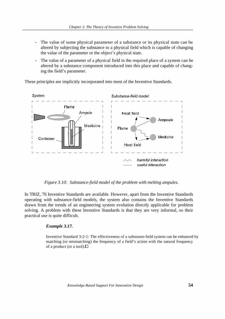
Chapter 3. The Theory of Inventive Problem Solving
Knowledge-Based Support For Innovative Design 54
• The value of some physical parameter of a substance or its physical state can bealtered by subjecting the substance to a physical field which is capable of changingthe value of the parameter or the object’s physical state.
• The value of a parameter of a physical field in the required place of a system can bealtered by a substance component introduced into this place and capable of chang-ing the field’s parameter.
These principles are implicitly incorporated into most of the Inventive Standards.
Figure 3.10: Substance-field model of the problem with melting ampules.
In TRIZ, 76 Inventive Standards are available. However, apart from the Inventive Standardsoperating with substance-field models, the system also contains the Inventive Standardsdrawn from the trends of an engineering system evolution directly applicable for problemsolving. A problem with these Inventive Standards is that they are very informal, so theirpractical use is quite difficult.
Example 3.17.
Inventive Standard 3-2-1: The effectiveness of a substanc e-field system can be enhanced bymatching (or mismatching) the frequency of a field’s action with the natural frequencyof a product (or a tool).�
+HDW�ILHOG
+HDW�ILHOG
)ODPH
$PSRXOH
0HGLFLQH
)ODPH
$PSXOH
0HGLFLQH
&RQWDLQHU
KDUPIXO�LQWHUDFWLRQ
XVHIXO�LQWHUDFWLRQ
6\VWHP 6XEVWDQFH�ILHOG�PRGHO

Chapter 3. The Theory of Inventive Problem Solving
55 Knowledge-Based Support For Innovative Design
3.4.6 Pointers to Scientific-Engineering Effects
Another problem-solving technique suggested by TRIZ consists of the collection of so-calledscientific-engineering effects. While principles for contradiction elimination and InventiveStandards do not produce recommendation in terms of what physical substances or fieldsshould be used, scientific-engineering effects provide the mapping between technical func-tions and known natural phenomena.
Studies of the patent collections indicated that the best and, as a consequence, more idealinventive solutions are obtained by utilizing natural phenomena previously unused in engi-neering domain. Knowledge of natural phenomena often makes it possible to avoid thedevelopment of complex and unreliable designs. For instance, instead of a mechanical designincluding many parts for the precise displacement of an object for a short distance, it is possi-ble to apply the effect of thermal expansion to control the displacement.
Finding relevant natural phenomena that would be capable of meeting a new design require-ment is one of the most important tasks in the early phases of design. However, it is nearlyimpossible to directly use formulations of natural phenomena in the form in which they aregiven in handbooks on physics or chemistry. The descriptions of natural phenomena availa-ble in handbooks or encyclopaedia yield information on the properties of the phenomenafrom a scientific point of view, and it is unclear how these properties can be used to deliverspecific technical functions.
TRIZ collection of scientific-engineering effects (Gorin [1973]) is designated to bridge a gapbetween engineering and science. Thus, the definition “scientific-engineering effect” impliesthat each natural phenomenon in this collection is identified with a multitude of various tech-nical functions that might be achieved on the basis of the phenomenon.
The search for effect is possible through indicating a design requirement to be met by a newdesign. These requirements are represented in the collection of the effects in terms of prede-fined technical functions. Each technical function indicates an action to be provided by a sys-tem to be designed, for instance, “to move a loose body” or “to change density”.
Each technical function refers to a list of several possible effects to use, which makes it pos-sible to apply even well-known effects in non-ordinary situations. The organization of thepointer to physical effects is shown in Figure 3.6.
Example 3.18.
In the TRIZ pointer to physical effects, the function “to achieve a precise displacement”refers to the physical effect of magnetostriction. The applicability of this effect for per-forming the function is illustrated by solving the problem of achieving a precise distancebetween a magnetic head and the recording surface in a tape recorder. One end of themagnetostrictive rod is fixed in a rigid position and the opposite end is fixed to the head.A magnetic field is applied to compress the rod exactly to the required distance betweenthe head and the recording surface (SU A.c. 517 927).�

Chapter 3. The Theory of Inventive Problem Solving
Knowledge-Based Support For Innovative Design 56
Figure 3.11: Organization of the pointer to scientific-engineering effects
The way of organizing the TRIZ collection of scientific-engineering effects is similar to theapproach used by the German School of Design for developing the Design Catalogues (Pahl& Beitz [1984]). However, there are two distinctions between the TRIZ pointers to theeffects and the Design Catalogues: first, TRIZ understands a technical function in thebroader sense, and any physical function is regarded as generic with respect to producing amultitude of technical functions; second, TRIZ contains unique collections of geometricaland chemical effects which relate chemical (Salamatov [1988]) and geometrical (Vikentiev& Efremov [1989]) knowledge with technical functions. The collections of geometrical andchemical effects are organized in the same way as the collection of physical effects.
Example 3.19.
Many of the technical functions can be performed by using various geometrical shapes.For instance, the function “to obtain different properties on one side of an object” can beprovided with the use of a Möbius tape. The Möbius tape is a twisted tape, glued in aring. While rotating, it has a one-sided surface, whereas actually it has a two-sided sur-face. By covering both surfaces of the sheet with different materials, it is possible toobtain two different properties on one side of the sheet.�
Separate gas and liquid
Orient particles
Change shape
Retain substance
Change density
.....
Curie Point
Evaporation
Ferromagnetism
Crystallization
..........
..........
..........
Design cases
List of technical functions Repository of effects Database ofprevious designsolutions

Chapter 3. The Theory of Inventive Problem Solving
57 Knowledge-Based Support For Innovative Design
3.5. Algorithm of Inventive Problem Solving.
After applying TRIZ problem solving techniques, there might be a situation when the inven-tive principles, inventive standards or the pointer to scientific-engineering effects do noteliminate the formulated contradiction. This situation indicates that the actual origin of theproblem has not been extracted during the problem analysis phase. Although the three prob-lem solving techniques discussed above are rather powerful and may be successfully used,they have the following disadvantages:
1. The techniques operate with fuzzy information about an engineering system and itssurrounding environment. They are not supported by tools for verifying a problemstatement. As a consequence, a model of a problem is constructed ad hoc and mayinclude incorrectly chosen components.
2. An ill-defined inventive situation can be decomposed into various engineering con-tradictions and substance-field models. There is no tool available in inventive prin-ciples or Inventive Standards to evaluate what model to choose from a number ofalternatives.
3. The TRIZ problem-solving techniques do not remove psychological inertia in full:specific engineering terms shackle an inventor to ingrained concepts about technicalobjects, thus significantly complicating the search for new solutions.
Inventive principles and Inventive Standards are supposed to conduct superficial analysis ofthe problem. In many situations, the most difficult inventive problems are featured by a phys-ical contradiction: the same component of a technical system has to have mutually exclusivevalues of the same physical parameter or should be in different physical states. In contrast toprocedures for formulating the engineering contradictions and substance-field modelling, thephysical contradiction often may not be directly extracted from the initial problem descrip-tion. To find what physical contradictions are present in the system, a more sophisticatedproblem analysis is needed. To translate the initial problem statement into the physical con-tradiction, an integrated technique called Algorithm of Inventive Problem Solving (ARIZ) wasdeveloped. ARIZ focuses on modeling a problem as a physical contradiction and its elimina-tion.
ARIZ systematizes the use of various types of TRIZ modelling techniques. Following theARIZ steps, a designer is able to gradually refine its problem model starting with an engi-neering contradiction and translating it into a physical contradiction.
ARIZ-85B (Altshuller [1986]) consists of several parts aimed at supporting all phases of theproblem solving process with TRIZ: from the initial problem statement to the qualitativeevaluation of the obtained solution. In addition, ARIZ includes a large collection of previousdesign cases which are various industrial solutions accumulated during the long-term devel-opment and use of TRIZ. The collection of design cases has illustrative aid and is used to

Chapter 3. The Theory of Inventive Problem Solving
Knowledge-Based Support For Innovative Design 58
help with a better understanding of TRIZ techniques. Many of the cases store detailed infor-mation on how solutions were obtained.
The repository of design cases can be viewed as a storage of inventive experience with tack-ling difficult situations occurring in different steps of problem solving. This information isused to guide the process of solving a new problem.
In the following subsections we will describe the ARIZ structure and a case study illustratingproblem solving by ARIZ. To make understanding of the basic ARIZ concepts more clear,we will structure a problem solving process by ARIZ into three steps: i) problem formula-tion; ii) problem modeling and iii) problem solving.
3.5.1 Problem formulation
The first step of ARIZ is the analysis of an inventive situation and decomposition of the ini-tial situation into manageable subproblems. A selection of a problem to solve from the sub-problems is made according to the following principle: a subproblem that involves minimalmodifications to obtain a solution should be selected.
Example 3.20.
Suppose the following situation: to indicate the level of a combustible liquid in a tank, afloat detector is used. When the level of the liquid reaches the top of the tank, a conduc-tor placed on the float and the inner surface of the tank’s top close a circuit and a signalis generated (Figure 3.7). However, when there is a small gap between the float’s con-ductor and the tank’s inner surface, a spark may jump across them, that can lead toinflammation of the liquid. In this case, an inventive situation takes place. It can bedecomposed into a set of subproblems: to prevent the spark jumping, to isolate the gapfrom the liquid, to replace an electrical system with some other system, etc.
Figure 3.12: A problem of spark jumping
lamp
tankconductor
floatliquid
electricalsource
Chapter 3. The Theory of Inventive Problem Solving
59 Knowledge-Based Support For Innovative Design
As said above, ARIZ recommends to solve a mini-problem: a solution should be foundwith minimal modifications of the existing system. The mini-problem is formulated inthe following way: “An engineering system for providing float detection includes: thefloat, the combustible liquid, the tank, the conductor, the conductors, an electricalsource, electrical current and a lamp. It is necessary to prevent the spark jumping withminimal system modifications.”
3.5.2 Problem modeling
After the mini-problem has been formulated, it is represented in terms of an engineering con-tradiction. In ARIZ, the formulation of an engineering contradiction slightly differs from theformulation used in the inventive principles (see Section 3.5). The ARIZ formulation of theengineering contradiction consists of two parts. Both parts indicate opposite situations of thecontradiction and relevant positive and negative effects produced in both situations.
Example 3.20 (continued).
The engineering contradiction corresponding to the mini-problem formulated in the pre-vious section:
Contradiction A: An electrical current must be within the system to provide indication ofthe liquid level, but the liquid can explode as a result of a spark jumping;
Contradiction B: Without a current, the spark does not appear, but the level detection isnot provided.
After this step has been completed, ARIZ suggests the construction of a substance-fieldmodel of the problem and to attempt to find a solution based on Inventive Standards. How-ever, even if a solution is found, one needs to continue the work with ARIZ because there isno guarantee that the best possible solution has been found.
The next step is an analysis of the available substance-field and other resources. Cheap avail-able resources should be used as much as possible to solve the problem with the lowest pos-sible cost. At this step, the so-called Ideal Result is formulated. The Ideal Result displays theultimate goal of problem solving: the desired result should be obtained without introducingnew components into the existing system. This also means that new components that need tobe introduced to obtain a solution should utilize or be derived from available resources.
The next step is define an operation zone and operation time. Operation zone defines a partof space where the negative effect takes place. Operational time specifies at what time inter-val(s) the negative effect occurs.
After a comprehensive analysis of the problem has been completed, the engineering contra-diction is transformed into a physical contradiction. There are two types of physical contra-dictions: a macrolevel contradiction and a microlevel contradiction. The macrolevelcontradiction is represented in terms of exclusive demands on the physical state of some
Chapter 3. The Theory of Inventive Problem Solving
Knowledge-Based Support For Innovative Design 60
component in the system. The microlevel contradiction specifies where and when the parti-cles of a substance should provide a required useful effect and must not cause the negativeeffect.
Example 3.20 (continued).
An operation zone includes the upper surface of the float, an internal surface of the tankwhere the contact is closed, and a distance between them when the spark jumps. Anoperation time includes the time interval for the spark to jump.
The macrolevel contradiction: an electrical current should be in the system to providedetection and should not be in the system to prevent the spark from jumping.
The microlevel contradiction: electrons must flow when both conductors are closed andshould not flow when they are opened regardless of the distance between the contacts.
3.5.3 Problem solving
The problem solving phase consists of two parts:
1. Decide on what modification of the design prototype has to be done to eliminate thephysical contradiction.
2. Decide on how this modification can be achieved by using a natural phenomenonthat will make the solution physically realisable.
These parts are probably the most difficult from the point of view of the designer. Themacro- and microlevel contradictions are the most precise problem formulations which resultfrom accurately performing previous ARIZ steps. At this phase, principles for physical con-tradiction elimination are used. They provide guidelines to specify a new function that has tobe realised to obtain the solution and what physical effect can provide this function.
Example 3.20 (continued).
One of the principles for the elimination of physical contradictions states that the contra-diction formulated at the previous step can be resolved by the “division of contradictoryproperties in time”. Thus, we obtain a new formulation of the problem: “the electricalcurrent has only to be generated when the contacts are closed, and must not be generatedwhen the contacts are opened.”
To solve the problem in such a formulation, after using the pointer to physical effects itwas suggested to use the Seebeck effect: appearance of electromotive force in contactingheterogeneous metals with different values of thermopowers. One of the possible solu-tions is based on this effect: the tank and the conductor placed on the float are made ofdifferent metals (Figure 3.8). The metal which the tank is made of has the value of ther-mopower S1 and the metal which the float conductor is made of has the value of ther-mopower S2 respectively. When contacting, they form a cold junction of a

Chapter 3. The Theory of Inventive Problem Solving
61 Knowledge-Based Support For Innovative Design
thermocouple, whereas another junction is formed by a new conductor made from thesame material as the float’s conductor and placed outside the tank. This new conductor issupplied with a heating source. Since a current can only be generated in a closed circuit,in this case the physical contradiction is eliminated: the current only arises when con-tacts are closed (SU Author Certificate 904 532).�
Figure 3.13: Solution to the problem of preventing a spark jumping
If the solution can not be found after the final phase has been accomplished, ARIZ recom-mends to go back to the phase of problem formulation and conduct the problem analysismore carefully or to select another subproblem. ARIZ also includes special rules to help withmanaging this situation. The overall process of problem solving with ARIZ is depicted inFigure 3.9.
3.6. Summary
We have presented a brief introduction to and overview of major components of the Theoryof Inventive Problem Solving. Our goal was to demonstrate that a systematic and knowl-edge-based approach to solving inventive problems is possible. TRIZ problem-solving tech-niques and collections of scientific knowledge can be regarded as knowledge sources forbuilding an AI-based system for conceptual design.
On the other hand, TRIZ concepts and techniques are still far from being formal enough tobuild a computational model of design upon. To understand how TRIZ knowledge can bestructured, modeled and represented in an AI system, we have to formulate and solve anumber of problems. In the next chapter, we perform a critical overview of TRIZ from theknowledge-based point of view and formulate these problems.
tank (S2)
conductor (S1)
new conductor (S1)heat flow

Chapter 3. The Theory of Inventive Problem Solving
Knowledge-Based Support For Innovative Design 62
Figure 3.14: Algorithm of Inventive Problem Solving
6ROXWLRQ
$QDO\VLV�DQG�GHFRPSRVLWLRQRI�LQYHQWLYH�VLWXDWLRQ
)RUPXODWLRQ�RI�PLQL�SUREOHP
3UREOHP�PRGHOLQJ
)RUPXODWLRQ�RI�DQ�HQJLQHHULQJ�
)RUPXODWLRQ�RI�D�VXEVWDQFH�ILHOG�
$QDO\VLV�RI�DYDLODEOH�VXEVWDQFHV��ILHOGV�DQG�VSDWLDO�WHPSRUDO�UHVRXUFHV
)RUPXODWLRQ�RI�D�SK\VLFDO�FRQIOLFW
3UREOHP�VROYLQJ
$SSOLFDWLRQ�RI�SULQFLSOHV�IRU
SK\VLFDO�FRQIOLFW�HOLPLQDWLRQ
$SSOLFDWLRQ�RI�SK\VLFDO�HIIHFWV
6HOHFWHG�SUREOHP
3UREOHP�IRUPXODWLRQ
(QJLQHHULQJ�FRQIOLFW
6XEVWDQFH�ILHOG�PRGHO
/LVW�RI�UHVRXUFHV
0DFUR��DQG�PLFUROHYHOSK\VLFDO�FRQIOLFWV
0RGHO�RI�D�VROXWLRQ
3UREOHP�IRUPXODWLRQ
PRGHO
$5,=�6WHSV 5HVXOW
FRQIOLFW
Chapter 4. TRIZ Critique
63 Knowledge-Based Support For Innovative Design
Chapter 4. TRIZ Critique
4.1. Introduction
In the previous chapter, we presented an introduction into the Theory of Inventive ProblemSolving (TRIZ). A goal of this chapter is to study what problems will be faced during thedevelopment of computer aid for TRIZ-based innovative design. To do this, we perform ananalysis of TRIZ problem solving techniques from the knowledge-based point of view.
First, we compare TRIZ and the German School of Systematic Design and summarize thecontribution of TRIZ into design science. Second, we discuss TRIZ problem solving tech-niques from the position of developing a knowledge-based system (KBS). We also showwhy a computational model of innovative design can not build upon existing TRIZ tech-niques. Third, we discuss advantages and disadvantages of a formal theory of innovativedesign which is closely related to our study and was developed in Russia.
We also show the difference between available TRIZ-based software packages and CAD/CAM systems.
At the end of the chapter, we summarize general problems which have to be solved in orderto organize knowledge-based support for innovative engineering design.
4.2. TRIZ contribution to design science
4.2.1 TRIZ and German School of Systematic Design
Since TRIZ belongs to the category of systematic methods, it would be useful to compareTRIZ with some other systematic design method. Malmqwist et al. [1996] performed a com-

Chapter 4. TRIZ Critique
Knowledge-Based Support For Innovative Design 64
parative study of classical TRIZ1 and Systematic Approach of Pahl and Beitz (SAPB) whichis claimed to be the most internationally accepted systematic design methodology. Theresults of this study are demonstrated in Table 4.1.
1. A number of TRIZ versions are known which slightly differ from the original TRIZ proposed by Altshuller. For instance, Altshuller’s TRIZ couples physical effects with 30 general functions while the Invention Machine software package specifies 264 standard functions. Further in the text, we will label Altshuller’s version of TRIZ as “classical TRIZ”.
7$%/(������Comparison between classical TRIZ and SABP (adapted from Malmqwist et al. [1996])
Aspect Classical TRIZ SABP
Scope Inventive phase of design, Difficult problems, Component design
Entire Design Process, Simple and difficult problems, System Design
Task clarification
Trends of Technology Evolution General procedure
Problem formulation
Identified contradiction Abstraction of an essential problem
Systematic methods
Matrix of inventive principlesFunctions coupled to physical effectsPrinciples for Substance-Field transformation
Functions coupled to physical effects and machine components
Creative methods
Not included Brainstorming, Synectics, 6-3-5 method, Delphi method.
Function vocabulary
30 standard functions 5 generally valid functions
Solution space Restricted to best known solutions All possible solutions considered
Product models Substance-field model Design Specifications, Function structure, Concept, Component structure
Principles Principles for contradiction eliminationPrinciples for substance-field modification
Rules, principles and guidelines for all phases of the design process
Knowledge base Physical, chemical and geometrical effectsInventive PrinciplesTrends of Technology EvolutionSelected Patents
Physical effectsDesign CataloguesEngineering knowledge
Evaluation Not available Use-value analysis VDI 2225
Learning time Long Short
Computer support Commercial Research prototypes
Chapter 4. TRIZ Critique
65 Knowledge-Based Support For Innovative Design
As seen from the table, TRIZ primarily focuses on the conceptual phase of design whileSAPB aims at supporting every step of the overall design process. A support for conceptualdesign by SAPB is organized through: i) the use of cognitive methods for activating thinkingprocess and ii) browsing through a very general description of physical effects. Apart fromcoupling physical principles with generally valid functions, SABP does not contain system-atic means to solve particular inventive problems. In contrast to TRIZ, SAPB is unable todeal with ill-defined inventive problems.
However, SAPB contains a procedure for evaluating new design solutions while TRIZ doesnot. Design catalogues are also of a great help in finding solutions when the functionality ofa solution has been clarified.
As a conclusion, TRIZ and SAPB may be regarded as complementary methods rather thanalternative. TRIZ can be used for generating novel design concepts and clarifying functional-ity of the concepts while SAPB can be used for mapping specific functions onto solutionsavailable in Design Catalogues.
4.2.2 TRIZ contribution to science of design
Since TRIZ is mostly comprised of a number of heuristics, it is difficult to evaluate from thepoint of view of exact sciences. Unlike fundamental sciences, TRIZ is not based on the axio-matic approach and does not include formal means for problem solving and verification ofresults. Instead, its techniques resulted from a comprehensive study of previous engineeringexperience that does not guarantee that the techniques will be applicable to every situationthat may occur when designing new products. No proof of absolute applicability is possibledue to the heuristic nature of TRIZ.
On the other hand, TRIZ discovered a number of principles and introduced new conceptswhich, although have not been formalized yet, have proven their applicability for solvingpractical engineering problems and considerably accelerating the process of new productdevelopment. This fact should not be neglected when studying TRIZ. Many years of experi-ence with using TRIZ indicated that the discovered patterns and principles can be success-fully applied to solve virtually any inventive problem (Altshuller [1988]). For this reason,TRIZ rapidly became a part of the engineering curriculum worldwide as a general methodol-ogy for conceptual design of new products (Ouellette [1996]) and developing new technolo-gies. An example of using TRIZ for developing a new technology for direct manufacturingof metal parts is presented by Apelskog Killander [1996].
In summary, major contributions of TRIZ to engineering are:
• TRIZ discovered a systematic nature of technology evolution and described anumber of domain-independent evolution trends.
• TRIZ introduced a new classification of design solutions.

Chapter 4. TRIZ Critique
Knowledge-Based Support For Innovative Design 66
• TRIZ proposes to regard a contradiction as a cause of inventive problems and statesthat inventions results from eliminating contradictions.
• A set of basic principles for contradiction elimination was proposed.
• Access to the basic principles was organized in a systematic way.
• TRIZ proposed to model design products in terms of substance-field interactionsand apply generic patterns to transform the physical structure of products.
• TRIZ proposed a novel way to couple physical principles and technical functions.
We believe that TRIZ concepts such as contradictions and principles for substance-fieldmodelling might be used for developing a fundamental science of innovative engineeringdesign.
4.3. Critique of TRIZ
In this section, we perform a brief critical overview of TRIZ problem solving techniques pre-sented in Chapter 3 from the knowledge-based point of view.
4.3.1 Trends of Technology Evolution
Although the Theory of Technical System Evolution (TTSE) is claimed to be of a largeimportance for evaluating existing design solutions and predicting future solutions, it isunclear how to use it. Many TRIZ schools refer to significant difficulties in teaching TTSE tostudents because of the generic nature of evolution patterns and the lack of a product modelTTSE would be able to deal with. For these reasons, we do not see a possibility of represent-ing TTSE in a formal and structured way and will not use it in our further study.
4.3.2 Principles for contradiction elimination
As shown in Chapter 3, one of the most important TRIZ achievements which brings a betterunderstanding of innovative engineering design is that TRIZ regards the process of technol-ogy evolution as the successive elimination of various types of contradictions. A contradic-tion arises when the designer’s wish to improve the performance of an existing system byredesigning the system results in a deterioration of another system’s parameter.
To eliminate the contradiction and prevent other system parameters from deterioration, TRIZrecommends that a problem be formulated in terms of a pair of conflicting parameters andeliminate the conflict using inventive principles. For instance, the contradiction between theweight of a moving object and its speed is eliminated by using the “Counterweight Principle”which states that “to compensate for the weight of the object it should be merged with otherobjects that have lifting forces”. Examples of other inventive principles are “to increase a
Chapter 4. TRIZ Critique
67 Knowledge-Based Support For Innovative Design
degree of object’s fragmentation”, “to place one object inside another”, etc. (see AppendixA). As seen, TRIZ principles are formulated in a very general manner and do not indicatewhat should be done with respect to a particular problem.
Summarizing, there are four shortcomings of the existing approach to solving inventiveproblems by formulating and eliminating contradictions:
1. No formal definition of a contradiction is available in TRIZ.
2. TRIZ does not provide exact recommendations on how to formulate contradictionswith respect to a particular problem. As a result, a contradiction is constructed ad-hoc since no analysis of a prototypical design is performed.
3. To identify an inventive principle which has to be used for solving a problem repre-sented as a specific conflict, the conflict has to be reformulated in terms of general-ized engineering parameters. However, this can only be done intuitively since notranslation technique is available in TRIZ.
4. Inventive principles do not propose a solution to a given problem. They only recom-mend a method which was used to solve a similar contradiction before.
For these reasons, the problem solving process turns out to be a process of numerous itera-tions until an appropriate inventive principle is identified. Furthermore, no quantitative rea-soning is supported by TRIZ thus making it impossible to evaluate feasibility of solutions.
To eliminate these shortcomings, a formal definition of the contradiction concept is neces-sary. It should allow the designer to define contradictions in terms of specific parametersafter an appropriate analysis of product models has been performed. This will make it possi-ble to derive contradictions from product models. However, this can be only be done afteragreeing upon how to model diverse design products.
4.3.3 Substance-Field Modelling
Inventive Standards (Section 3.7) deal with more specific problem formulations presented interms of interactions between substances and fields. Altshuller points out that InventiveStandards are an advanced form of inventive principles since they relate conflicts and physi-cal effects. However, this relation remains implicit since no contradiction is identified whena problem is modelled as a set of interacting physical objects.
The next disadvantage is that it is unclear which components of a system should be includedin the model and how modelled components are related except interaction via physical fields.To explain what he means by field, Altshuller writes (Altshuller [1984], p. 53):
“In technology, the term field is used in a broader sense: there is space to eachpoint of which a certain vector or scalar magnitude stands in relation. Such fieldsare often linked with vector or scalar bearer-substances, the temperature field, the
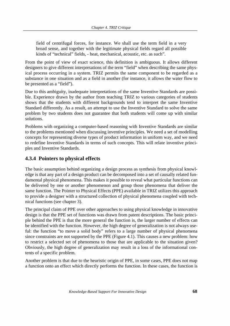
Chapter 4. TRIZ Critique
Knowledge-Based Support For Innovative Design 68
field of centrifugal forces, for instance. We shall use the term field in a verybroad sense, and together with the legitimate physical fields regard all possiblekinds of “technical” fields, - heat, mechanical, acoustic, etc. as such”.
From the point of view of exact science, this definition is ambiguous. It allows differentdesigners to give different interpretations of the term “field” when describing the same phys-ical process occurring in a system. TRIZ permits the same component to be regarded as asubstance in one situation and as a field in another (for instance, it allows the water flow tobe presented as a “field”).
Due to this ambiguity, inadequate interpretations of the same Inventive Standards are possi-ble. Experience drawn by the author from teaching TRIZ to various categories of studentsshows that the students with different backgrounds tend to interpret the same InventiveStandard differently. As a result, an attempt to use the Inventive Standard to solve the sameproblem by two students does not guarantee that both students will come up with similarsolutions.
Problems with organizing a computer-based reasoning with Inventive Standards are similarto the problems mentioned when discussing inventive principles. We need a set of modellingconcepts for representing diverse types of product information in uniform way, and we needto redefine Inventive Standards in terms of such concepts. This will relate inventive princi-ples and Inventive Standards.
4.3.4 Pointers to physical effects
The basic assumption behind organizing a design process as synthesis from physical knowl-edge is that any part of a design product can be decomposed into a set of causally related fun-damental physical phenomena. This makes it possible to reveal what particular functions canbe delivered by one or another phenomenon and group those phenomena that deliver thesame function. The Pointer to Physical Effects (PPE) available in TRIZ utilizes this approachto provide a designer with a structured collection of physical phenomena coupled with tech-nical functions (see chapter 3).
The principal claim of PPE over other approaches to using physical knowledge in innovativedesign is that the PPE set of functions was drawn from patent descriptions. The basic princi-ple behind the PPE is that the more general the function is, the larger number of effects canbe identified with the function. However, the high degree of generalization is not always use-ful: the function “to move a solid body” refers to a large number of physical phenomenasince constraints are not supported by the PPE (Figure 4.1). This causes a new problem: howto restrict a selected set of phenomena to those that are applicable to the situation given?Obviously, the high degree of generalization may result in a loss of the informational con-tents of a specific problem.
Another problem is that due to the heuristic origin of PPE, in some cases, PPE does not mapa function onto an effect which directly performs the function. In these cases, the function is
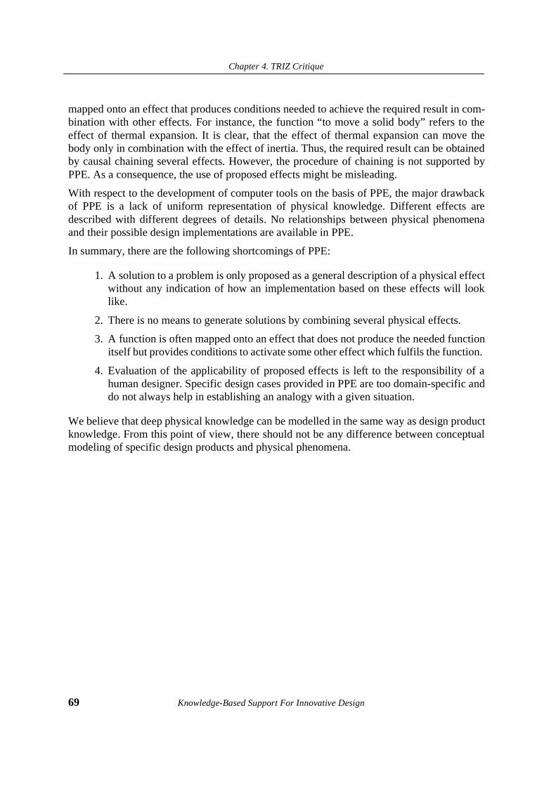
Chapter 4. TRIZ Critique
69 Knowledge-Based Support For Innovative Design
mapped onto an effect that produces conditions needed to achieve the required result in com-bination with other effects. For instance, the function “to move a solid body” refers to theeffect of thermal expansion. It is clear, that the effect of thermal expansion can move thebody only in combination with the effect of inertia. Thus, the required result can be obtainedby causal chaining several effects. However, the procedure of chaining is not supported byPPE. As a consequence, the use of proposed effects might be misleading.
With respect to the development of computer tools on the basis of PPE, the major drawbackof PPE is a lack of uniform representation of physical knowledge. Different effects aredescribed with different degrees of details. No relationships between physical phenomenaand their possible design implementations are available in PPE.
In summary, there are the following shortcomings of PPE:
1. A solution to a problem is only proposed as a general description of a physical effectwithout any indication of how an implementation based on these effects will looklike.
2. There is no means to generate solutions by combining several physical effects.
3. A function is often mapped onto an effect that does not produce the needed functionitself but provides conditions to activate some other effect which fulfils the function.
4. Evaluation of the applicability of proposed effects is left to the responsibility of ahuman designer. Specific design cases provided in PPE are too domain-specific anddo not always help in establishing an analogy with a given situation.
We believe that deep physical knowledge can be modelled in the same way as design productknowledge. From this point of view, there should not be any difference between conceptualmodeling of specific design products and physical phenomena.
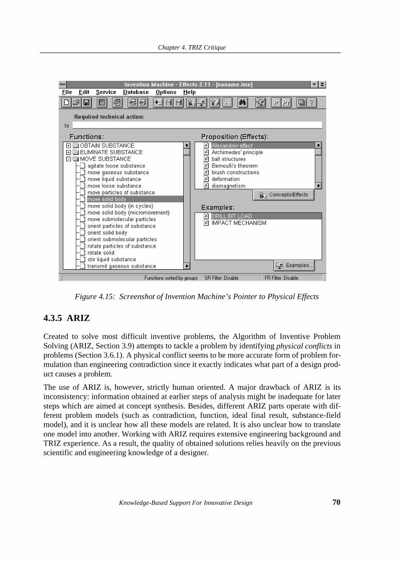
Chapter 4. TRIZ Critique
Knowledge-Based Support For Innovative Design 70
Figure 4.15: Screenshot of Invention Machine’s Pointer to Physical Effects
4.3.5 ARIZ
Created to solve most difficult inventive problems, the Algorithm of Inventive ProblemSolving (ARIZ, Section 3.9) attempts to tackle a problem by identifying physical conflicts inproblems (Section 3.6.1). A physical conflict seems to be more accurate form of problem for-mulation than engineering contradiction since it exactly indicates what part of a design prod-uct causes a problem.
The use of ARIZ is, however, strictly human oriented. A major drawback of ARIZ is itsinconsistency: information obtained at earlier steps of analysis might be inadequate for latersteps which are aimed at concept synthesis. Besides, different ARIZ parts operate with dif-ferent problem models (such as contradiction, function, ideal final result, substance-fieldmodel), and it is unclear how all these models are related. It is also unclear how to translateone model into another. Working with ARIZ requires extensive engineering background andTRIZ experience. As a result, the quality of obtained solutions relies heavily on the previousscientific and engineering knowledge of a designer.
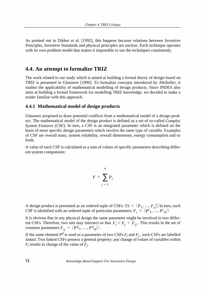
Chapter 4. TRIZ Critique
71 Knowledge-Based Support For Innovative Design
As pointed out in Dikker et al. [1992], this happens because relations between InventivePrinciples, Inventive Standards and physical principles are unclear. Each technique operateswith its own problem model that makes it impossible to use the techniques consistently.
4.4. An attempt to formalize TRIZ
The work related to our study which is aimed at building a formal theory of design based onTRIZ is presented in Glasunov [1990]. To formalize concepts introduced by Altshuller, itstudies the applicability of mathematical modelling of design products. Since INDES alsoaims at building a formal framework for modelling TRIZ knowledge, we decided to make areader familiar with this approach.
4.4.1 Mathematical model of design products
Glasunov proposed to draw potential conflicts from a mathematical model of a design prod-uct. The mathematical model of the design product is defined as a set of so-called ComplexSystem Features (CSF). In turn, a CSF is an integrated parameter which is defined on thebasis of more specific design parameters which involve the same type of variable. Examplesof CSF are overall mass, system reliability, overall dimensions, energy consumption and soforth.
A value of each CSF is calculated as a sum of values of specific parameters describing differ-ent system components:
A design product is presented as an ordered tuple of CSFs: . In turn, eachCSF is identified with an ordered tuple of particular parameters:
It is obvious that in any physical design the same parameter might be involved in two differ-ent CSFs. Therefore, two sets may intersect so that . This results in the set ofcommon parameters
If the same element Pij is used as a parameter of two CSFs Fi and Fj , such CSFs are labelledlinked. Two linked CSFs possess a general property: any change of values of variables withinFi results in change of the value of Fj.
F Pi
i 1=
n
∑=
TS F1 … F, n,⟨ ⟩=Fi Pi
1 … Pim, ,⟨ ⟩=
Fi Fj∩ Fij=Fij Pij
1 … Pijm, ,⟨ ⟩=

Chapter 4. TRIZ Critique
Knowledge-Based Support For Innovative Design 72
4.4.2 Conflict Formulation
With respect to the desired improvement of the system, two categories of CSF are distin-guished: positive (F+) and negative (F-). A CSF is positive when its value should increase(e.g. reliability). In contrast, a CFS is regarded as negative when its value should decrease(e.g., energy consumption).
Example 4.1.
The parameter mass of a hammer might be defined as a variable involved into both CSF+
Force and CSF- Energy Consumption. Therefore, an attempt to increase the forcethrough increasing the mass will lead to the growth of energy consumption.q
It is possible to define what linked CSFs will conflict by analysing their partial derivatives bya physical parameter P. Table 4.2 illustrates possible states.
In the situation when one of the partial derivatives can have both negative and positive signs(within different time intervals, for instance), this situation is labelled partial conflict.
7$%/(������
Condition Result
∂Fi+ / ∂P > 0 and ∂Fj
+ / ∂P > 0 no conflict
∂Fi+ / ∂P > 0 and ∂Fj
+ / ∂P < 0 conflict
∂Fi+ / ∂P < 0 and ∂Fj
+ / ∂P > 0 conflict
∂Fi+ / ∂P < 0 and ∂Fj
+ / ∂P < 0 no conflict
∂Fi+ / ∂P > 0 and ∂Fj
- / ∂P > 0 conflict
∂Fi+ / ∂P > 0 and ∂Fj
- / ∂P < 0 no conflict
∂Fi+
/ ∂P < 0 and ∂Fj- / ∂P > 0 no conflict
∂Fi+
/ ∂P < 0 and ∂Fj- / ∂P < 0 conflict
∂Fi- / ∂P < 0 and ∂Fj
- / ∂P < 0 no conflict
∂Fi- / ∂P < 0 and ∂Fj
- / ∂P > 0 conflict
∂Fi- / ∂P > 0 and ∂Fj
- / ∂P < 0 conflict
∂Fi- / ∂P < 0 and ∂Fj
- / ∂P < 0 no conflict
Chapter 4. TRIZ Critique
73 Knowledge-Based Support For Innovative Design
4.4.3 Problem solving
A potential conflict between two CSFs is expressed as the relation goal(P(X1),P(X2)), whichcan be interpreted in the following way: “a physical parameter P has to have two differentvalues at the same time: X1 (to satisfy Fi) and X2 (to satisfy Fj)”. This is similar to whatAltshuller defines as a physical conflict (Section 3.6.1): the same object has to possess twocontrary physical properties at the same moment in time or to have two different values ofthe same physical parameter.
A procedure for conflict elimination consists in the search for an object from a repository ofpredefined physical objects that can satisfy both conditions. For instance, a spiral is regardedas the object which under certain conditions satisfy two conflicting values of the parameter“length”. The spiral is long (if to look at the length of a line forming the spiral) and short (ifto look at the spiral diameter) at the same time. Therefore, the spiral possesses so-called dualproperties and is capable of resolving the conflict.
4.4.4 Discussion of Glasunov’s approach
A major advantage of Glasunov’s approach is that it defines a conflict in a formal way byanalysing a mathematical model of a design product. However, the concept of a ComplexSystem Feature still remains ambiguous. Furthermore, given a set of Complex System Fea-tures, no reasoning about a system’s behaviour is possible. As a consequence, a search for anobject with dual physical properties is only determined by two required values of a physicalvariable and there is no guarantee that the use of the selected object in an existing system willnot violate the overall system behaviour. A repository should store components with all pos-sible dual physical properties that does not seem possible due to a relative nature of proposeddefinition of duality. It is clear, that a spring as the object with two different values of thesame parameter might not be considered as a solution in every situation.
Another disadvantage is that the success of problem solving strongly depends on two factors:what CSFs are identified in every particular case and how many physical objects with dualproperties are stored in the repository. Provided the repository is large, there are no means toverify the applicability of the solutions without the participation of a human designer. In thiscase, the use of a mathematical model of a design product seems to be useless during the syn-thesis phase since we can not calculate quantitative values of the solution.
As a conclusion, to build a computational model of innovative design based on the Glasu-nov’s approach is possible. However, its applicability will be restricted to those problemswhich can be solved by using predefined objects with dual properties.
Chapter 4. TRIZ Critique
Knowledge-Based Support For Innovative Design 74
4.5. Computer-Aided TRIZ and CAD/CAM software
Recently, a number of software packages supporting design problem solving with TRIZ havebeen developed. Among them are Invention Machine (Tsourikov [1992]), Edison (***[]),and Innovation Workbench (Braham [1995]). Although all packages incorporate differentapproaches to represent TRIZ information and organize the problem solving process, theyform a new category of computer-aided design tools which support a conceptual phase ofengineering design.
While traditional CAD/CAM systems focus on processing and computing geometrical andmaterial aspects of specific designs (Amirouche [1994]), TRIZ-based software packagesstructure access to previous inventive experience stored in the form of inventive principlesand indexed physical principles. According to a given problem formulation, TRIZ-basedpackages propose information on what the generic behaviour of a design solution should berather than what form and geometry the solution should have.
In summary, TRIZ-based packages organize mapping between the function and behaviour ofa concept which is still to be found, whereas CAD/CAM systems map functional and geo-metrical specifications directly onto already known design solutions stored in the database.
In addition, CAD/CAM systems propose specific, “ready-to-manufacture” descriptions ofsolutions that makes such systems relatively easy to learn and use. TRIZ-based packages arewell-organized interactive systems which only help with finding general recommendationson how to solve problems, or at best, indicating what physical principles to use. A designershould be able to interpret this information and translate it into a feasible solution. No suffi-cient computer aid has been available so far to support this step. This causes certain difficul-ties in the use of the software by many designers since the gap between generalrecommendation and specific solution can be very large. It is our belief that to be accepted bya wide audience, TRIZ-based software has to bridge this gap and be able to generate solu-tions in terms of specific problems instead of displaying general recommendations.
4.6. Discussion
Until now, it was unclear how to structure design and scientific knowledge in order todevelop a knowledge-based system which will support reasoning about innovative andinventive designs. As follows from Altshuller’s studies of inventive activities, to makeinventions, the outstanding inventor uses his/her own experience which is usually based on5-7 empirically found inventive principles over the long time of practice. The inventor’sexperience thus comprises knowledge of different engineering and scientific areas thatmakes it possible to establish high-order analogies when solving new problems. However,too much of this knowledge remains implicit so no systematic use of it is possible.

Chapter 4. TRIZ Critique
75 Knowledge-Based Support For Innovative Design
To automate conceptual engineering design by modeling all available design and scientificknowledge and developing a comprehensive knowledge base capable of storing all thisknowledge does not seem to be possible at the moment. It would require an incomprehensi-ble amount of work to be done. In addition, there is no way available to establish links andrelations between design solutions drawn from different engineering disciplines at the levelof specific details. Although some general approaches to building very large engineeringknowledge bases are mentioned in the literature (Tyugu [1995], Ishi et al. [1995]), their fea-sibility has not been proven yet. Apart from that, even if the creation of such a knowledgebase becomes possible, no strategy is available to reason with this knowledge to obtaininventive solutions.
TRIZ tackles this problem by revealing high-order similarities between inventive solutions indifferent domains and making generic patterns behind these similarities explicit. However,the high degree of generalization makes a process of finding specific solutions difficult if notimpossible.
Known TRIZ-based software packages do not incorporate AI elements due to a lack of com-putational models of innovative design. It is the authors’ opinion that it would be prematureto directly incorporate TRIZ knowledge available in TRIZ literature into a knowledge-basedsystem unless we have clear understanding of how to support TRIZ with formal methods andrepresent TRIZ knowledge.
To summarize the discussion in the chapter, we can distinguish the following major short-comings of TRIZ with respect to its possible computer implementation in the form of aknowledge-based system:
• TRIZ techniques are meant for personal use. They propose no formal methods forproblem solving. Instead, empirical rules for restricting the search space of solutionsare introduced.
• The wealth of knowledge available in TRIZ is necessary for solving a large varietyof inventive problems but access to the needed specific knowledge might be trou-blesome.
• TRIZ does not operate with formal scientific categories thus making it impossible toapply quantitative constraints at the phase of problem formulation. However, it isoften the case.
• TRIZ definitions of physical concepts such as substances and fields are ambiguousand can not be adequately interpreted.
• Using a recommendation proposed by TRIZ for solving a specific problem requiresan extensive knowledge of different engineering domains and is not currently sup-ported by TRIZ. As a consequence, the user of TRIZ is supposed to possess a highdegree of expertise in engineering design.

Chapter 4. TRIZ Critique
Knowledge-Based Support For Innovative Design 76
• TRIZ does not include techniques for evaluation and verification of the obtaineddesign concepts.
• It takes a very long time to master the necessary skills for working with TRIZ evenwith the available computer aid.
We believe that TRIZ knowledge should be restructured and redefined. As the basis forrestructuring we have chosen a product-centered approach to design, i.e. strategic knowledgeshould be defined in terms of product knowledge.
To develop a TRIZ-based computational model of innovative design that could be incorpo-rated into a knowledge-based system we defined three major milestones of INDES project:
1. To develop a formal framework for modeling and representing product knowledgefor conceptual design in a uniform way.
2. To redefine major TRIZ concepts in terms of a product modelling framework.
3. To establish relations between TRIZ problem solving techniques and model strate-gic knowledge for generating new design concepts.
Throughout the remainder of this work, we will present the results of our study.
Chapter 5. A Knowledge-Centered Model of Systematic Innovative Design
77 Knowledge-Based Support For Innovative Design
Chapter 5. A Knowledge-Centered Model of Systematic Innovative Design
“The important thing for you is not how much you know, but thequality of what you know.”
Desiderius Erasmus (1469-1536)
5.1. Introduction
The project INDES (stands for “Invention Designer”) was initiated in 1993 within the frame-work of a more general STEVIN project at the Knowledge-Based Group of the University ofTwente. The STEVIN project has been aimed at studying what design methodologies arecurrently available and have been proven successful, and what AI modelling approaches andtechniques are best suited to model various phases of engineering design. The results of thestudy are going to be utilized for developing knowledge-based tools supporting variousphases of engineering design process. As a part of STEVIN, INDES focuses on modellinginnovative phases of engineering design (Mars et al. [1993]).
Among the prerequisites which had the impact on making decision to launch INDES werethe availability of the Theory of Inventive Problem Solving (TRIZ) discussed in the previouschapters and YMIR, an earlier development within STEVIN. YMIR is a domain-independent

Chapter 5. A Knowledge-Centered Model of Systematic Innovative Design
Knowledge-Based Support For Innovative Design 78
ontology which introduced a number of knowledge concepts for formal modelling and repre-senting generic design knowledge (Alberts [1993a, 1993b]).
Since both TRIZ and YMIR utilize a domain-independent approach to design and aim at sim-ilar goals - structuring knowledge for engineering design, we decided to study if it would bepossible to model TRIZ knowledge in terms of YMIR concepts.
This chapter presents results obtained after this study. First, we describe the goals of INDESand a problem scope. Second, we introduce a knowledge-centered model of innovativedesign based on TRIZ. This model will be used as a generic model from which a number ofmore specialized design models can be drawn from.
The next part of the chapter discusses different categories of knowledge for innovative engi-neering design. We show how an ontological approach to knowledge conceptualization canbe used to identify TRIZ object and strategic knowledge. In the next chapters, these knowl-edge concepts will be used to build a computational model of design.
At the end of the chapter, we present a knowledge-intensive model of innovative engineeringdesign.
5.2. INDES Project overview
In this section, we present INDES goals, problem area and scope.
5.2.1 INDES Goals
The primary goal of INDES is to develop a formal framework which could be used for fur-ther development of knowledge-based systems supporting innovative engineering design. Inaddition, a prototype of a knowledge-based system (KBS) capable of generating new designconcepts was planned to build.
Following a general methodology of KBS development presented in Hayes-Roth et al.[1983], INDES was divided into the following phases:
1. Analysis of available theoretical methods for innovative design. Identification of theproblem area and scope, requirements and knowledge sources.
2. Building a conceptual model of innovative design on the basis of the problem areaand scope defined.
3. Identification of key knowledge concepts and relations, task strategies and con-straints.
4. Developing a technique for formal modelling of knowledge and mapping key con-cepts and relations onto formal representations.
Chapter 5. A Knowledge-Centered Model of Systematic Innovative Design
79 Knowledge-Based Support For Innovative Design
5. Testing the feasibility of the framework through an industrial case study.
6. Developing a research prototype of a knowledge-based system for innovativedesign.
It was decided to restrict INDES to semi-automated reasoning about innovative solutions. Atthe moment it seems to be impossible to develop a KBS supporting full automated reasoningdue to a lack of AI methods supporting reasoning about commonsense knowledge. Howeveras seen from Altshuller’s theory, innovative design relies heavily on this type of knowledge.Instead, INDES aims at bringing a more structured approach into developing knowledge-intensive systems in the area of innovative design support systems.
5.2.2 Problem area and scope
In one of the early works on developing KBS for design, Brown & Chandrasekaran [1985]divided the innovative design solutions into two categories: inventions (such as creation ofthe wing) and innovations (such as creation of a wing with changeable geometry). Althoughsimilar to Altshuller’s definitions for inventions and innovations, they do not address the pre-scribed strategy for design. They just state what types of design solutions can be obtainedwith respect to already existing space of design solutions.
Using these definitions within the context of Altshuller’s explanation of a systematic naturebehind the process of generating innovative solutions we defined the scope of INDES asstudy and development of a knowledge-based support for conceptual engineering design.
Therefore, INDES should provide a general domain-independent methodology for organiz-ing a process of conceptual design. To do this, we formulated a number of more specificquestions which defined milestones of INDES:
• What design method(s) and knowledge sources are available for innovative design?
• What general model of a design process can be derived from the design method?
• What knowledge sources are needed to support the design model?
• How knowledge about design products can be modelled to enable reasoning with it?
• What techniques for knowledge formalisation and representation are available andbest suited to formalise knowledge for conceptual design?
• What computational models of design can be built on the basis of defined knowl-edge sources and reasoning strategies?
Futher in the work, we make an attempt to answer these questions.

Chapter 5. A Knowledge-Centered Model of Systematic Innovative Design
Knowledge-Based Support For Innovative Design 80
5.2.3 INDES definition of conceptual design
To define a problem area more clearly we introduce definitions of conceptual design anddesign concept in the context of INDES.
Definition 5.2.
Conceptual design is a process of mapping of new societal demands andrequirements onto a description of a physically realisable artefact which is pre-sented in terms of a design concept.
Definition 5.3.
Design Concept is a description of a physical structure of a designed artefact atthe conceptual level which lacks specific details, but consistent and informativeenough to provide correct instantiation of the concept into the description of afeasible design product.
5.2.4 INDES limitations
TRIZ is limited to finding innovative and inventive solutions to problems in areas of technol-ogy which deal with material and energy transforming systems. As a consequence, anINDES-based design model will not be suitable for solving problems in areas of informationor, for instance, business systems.
As mentioned in the previous chapter, as a problem-solving tool TRIZ does not include atechnique for comparison and evaluation of obtained solutions. We have therefore decided tolimit ourselves to building a model of a design process which does not include means forsolution evaluation. On the other hand, given the systematic nature of the search for mostappropriate knowledge using TRIZ, the number of solution concepts resulting from thesearch is relatively low. This makes it easy to perform an analysis of alternatives. We believethat a procedure for concept evaluation should be independent of the problem-solving meth-odology and might thus be easily adapted to any problem-solving methodology withoutchanging the methodology itself. As an example, we can refer to Nordlund [1994] and Kil-lander et al. [1995] to name a few works studying how TRIZ can be extended with an evalu-ation technique on the basis of Design Axioms (Suh [1990]).
5.3. Knowledge-centered model of innovative design
The key factor for developing effective design models that could be further incorporated asKBS is the availability of theoretical design methodology. As mentioned before, studies with

Chapter 5. A Knowledge-Centered Model of Systematic Innovative Design
81 Knowledge-Based Support For Innovative Design
AI in Design are divided between two groups of models: process-oriented and product-ori-ented. The first group concentrates on studying cognitive qualities of a designer or a designteam and modeling them in the form of directives. Since such studies result in inevitablyfuzzy and broad theoretical frameworks (see, for instance, Wilson et al. [1995]), specificmodels of design may not be derived from them. Knowledge-based systems implementing aprocess-oriented model of design can therefore be regarded as user-centered.
The advantage of the product-oriented approach is that it results in a designer-independentmodel of design which focuses on product qualities rather than on process organization. Aphilosophy behind this product-oriented approach thus coincides with Altshuller’s approachto innovative design which considers psychological inertia to be a major obstacle to findinginnovative solutions. Numerous TRIZ applications have proven Altshuller’s thesis that prop-erly structured knowledge wealth is a necessary attribute of successful inventive design.Using TRIZ any engineer no matter what creative abilities he/she possesses is able to solveinventive problems in a relatively short time provided access to the TRIZ knowledge reposi-tory. As a conclusion, we believe that KBS for early design phases should be knowledge-cen-tered rather than user-centered.
In the previous chapter, we presented an overview of the set of recommended practises tocome up with innovative solutions to the problem given based on the Theory of InventiveProblem Solving. We also described the Algorithm of Inventive Problem Solving (ARIZ)which integrates different TRIZ problem-solving techniques. Despite its undeniable practicalusefulness in providing a designer with methodological support, ARIZ can hardly beregarded as an appropriate model of design process ready to be transferred onto a computer.A major drawback of ARIZ is that it mixes various problem representations and operateswith different models of problems and technical systems. Finally, it is unclear how to trans-late between one or another representation performing ARIZ steps.
To build a consistent model of TRIZ-based design that could be implemented in KBS, wepropose to separate between two categories of innovative design tasks different in the typesof initial design specifications and knowledge sources able to deal with each problem repre-sentation:
1. Innovative Redesign. The distinguishing feature of this type of design is that aproblem is formulated on the basis of the desired improvement to an existing designproduct. It might be either as a contradiction between two parameters or a sub-stance-field model which contains an undesired interaction. In the first case, princi-ples for contradiction elimination should be used to produce a recommendation onhow to solve the problem. Alternatively, the Inventive Standards are to be used tomodify the substance-field model.

Chapter 5. A Knowledge-Centered Model of Systematic Innovative Design
Knowledge-Based Support For Innovative Design 82
2. Innovative design from physical principles. A problem is represented as a func-tion a new design product has to deliver. No existing (or known) design product orcomponent is able to fulfil the function properly. In this case, the Pointers to naturalphenomena are then to be used to identify the function with one of the predefinedfunctions and map the function onto a generic design concept.
Figure 5.1 depicts a general model of TRIZ-based innovative design. Partly, this model issupported by the INVENTION MACHINE system (Tsourikov [1992]). However, INVEN-TION MACHINE does not perform reasoning in terms of user-defined problems. To enablesuch reasoning, TRIZ-based KBS must be able to deal with specific task knowledge, select anappropriate knowledge source and propose a solution in terms of the problems given.
Since we defined knowledge as a key point in our approach, in the next sections, types ofknowledge we use to model and represent knowledge of TRIZ will be discussed.
5.4. Knowledge categories for innovative design
In this section, we discuss a modern AI approach to distinguish various categories of knowl-edge. We show how knowledge for innovative engineering design can be divided into fourcategories: deep, shallow, object and strategic. In turn, we distinguish two subcategories forobject knowledge: primitive and complex.
5.4.1 Deep and shallow knowledge
The early success of knowledge-based systems refers to the mid-seventies when expert sys-tems based on knowledge expressed in the form of rules were designed and applied to solvepractical problems in various domains. The majority of such systems served diagnostic pur-poses. Their distinguishing feature was the use of shallow knowledge, that is, knowledgeacquired by an expert without understanding the underlying reasons. As a consequence, aknowledge-based system built on shallow knowledge was unable to give an explanation ofits reasoning nor validate produced results.
In the 1980s, a major paradigm shift was observed in AI when Lenat and Feigenbaum [1987]introduced the knowledge principle1 which dramatically changed the view on knowledge-based systems development. According to the principle, an AI program performs well if itknows a great deal about the task and domain where it operates.
According to the knowledge principle, the broader the domain is, the more complex andextensive a knowledge base for this domain has to be. On the other hand, if the knowledgebase only incorporates shallow knowledge, it will inherit all the disadvantages of shallowknowledge no matter what size the knowledge base is. The only known way to tackle this sit-
1. Also known as “knowledge is power”

Chapter 5. A Knowledge-Centered Model of Systematic Innovative Design
83 Knowledge-Based Support For Innovative Design
uation is to introduce deep knowledge into the AI program. In contrast to shallow knowl-edge, deep knowledge is a fundamental building block of understanding. A good example ofdeep knowledge is a fundamental knowledge of the laws of nature. The role of deep knowl-edge is twofold: first, to provide casual links between shallow knowledge to enable explana-tion and second, to decrease the degree of inconsistency in the knowledge base.
Basically, in any domain both types of knowledge can be distinguished which are relative toeach other. In TRIZ, both shallow and deep knowledge can be distinguished too. Forinstance, the principles for engineering contradiction elimination can be regarded as shallowknowledge with regard to the trends of technical systems evolution. Suppose the rule for con-tradiction elimination is defined as:
IF the length of a movable object is to be increased
AND the weight of the object is not allowed to increase
THEN the object must be fragmented.
Then, despite this rule of thumb being applicable to most inventive problems containing thesame contradiction, it still does not explain why the object must be fragmented. In somecases, it is unclear how to produce such fragmentation despite the fact that the word “frag-mentation” might be interpreted in many ways. Moreover, the fragmentation is not alwayspossible, especially when the system has reached its final phase of evolution and tends to bereplaced with another system.
At the same time, the trend of transition to the microlevel explains why fragmentation is pro-posed to resolve this particular type of contradiction. Therefore, the trend of transition to themicrolevel can be regarded as a part of the deep knowledge level in TRIZ. As a consequence,all TRIZ trends of evolution are deep knowledge with respect to the specific rules of contra-diction elimination.
Most KBS, especially those developed for commercial purposes, do not require a deep levelof knowledge analysis. As a consequence, they are built on codifying relatively shallowknowledge. However, the more knowledge-intensive a system is to be built the greater thedepth of analysis is necessary to provide an effective reasoning about domain and taskknowledge. As seen from the previous chapter, TRIZ incorporates knowledge of variousdegree of deepness. The use of more deep knowledge results in solutions with a higherdegree of feasibility. Besides, deep knowledge must be presented in a KBS to provide acheck against violation of basic physical laws when inferring a new solution.
We must note that in INDES, no design model based on explicit use of the trends of evolu-tion is proposed. Instead, we use Altshuller’s principles for inventive design which implicitlyincorporate the evolution trends with respect to specific tasks.

Chapter 5. A Knowledge-Centered Model of Systematic Innovative Design
Knowledge-Based Support For Innovative Design 84
Figure 5.1: Knowledge-centered model of TRIZ-based innovative design
Initial problem(demands and preferences)
FunctionContradiction Physical
Problem
Knowledgesources
representation
Solution concept
Evaluation NegativeReformulation
Positive
Innovative Redesign Design from physical principles
structure
Analogouscases
Generalrecommendation
Transformedphysical structure
Physicalphenomenon
Analogouscases
InventiveStandards
InventivePrinciples
Analogouscases
Pointers tonatural
phenomena
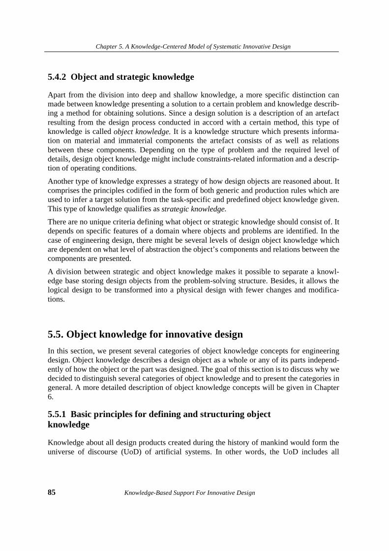
Chapter 5. A Knowledge-Centered Model of Systematic Innovative Design
85 Knowledge-Based Support For Innovative Design
5.4.2 Object and strategic knowledge
Apart from the division into deep and shallow knowledge, a more specific distinction canmade between knowledge presenting a solution to a certain problem and knowledge describ-ing a method for obtaining solutions. Since a design solution is a description of an artefactresulting from the design process conducted in accord with a certain method, this type ofknowledge is called object knowledge. It is a knowledge structure which presents informa-tion on material and immaterial components the artefact consists of as well as relationsbetween these components. Depending on the type of problem and the required level ofdetails, design object knowledge might include constraints-related information and a descrip-tion of operating conditions.
Another type of knowledge expresses a strategy of how design objects are reasoned about. Itcomprises the principles codified in the form of both generic and production rules which areused to infer a target solution from the task-specific and predefined object knowledge given.This type of knowledge qualifies as strategic knowledge.
There are no unique criteria defining what object or strategic knowledge should consist of. Itdepends on specific features of a domain where objects and problems are identified. In thecase of engineering design, there might be several levels of design object knowledge whichare dependent on what level of abstraction the object’s components and relations between thecomponents are presented.
A division between strategic and object knowledge makes it possible to separate a knowl-edge base storing design objects from the problem-solving structure. Besides, it allows thelogical design to be transformed into a physical design with fewer changes and modifica-tions.
5.5. Object knowledge for innovative design
In this section, we present several categories of object knowledge concepts for engineeringdesign. Object knowledge describes a design object as a whole or any of its parts independ-ently of how the object or the part was designed. The goal of this section is to discuss why wedecided to distinguish several categories of object knowledge and to present the categories ingeneral. A more detailed description of object knowledge concepts will be given in Chapter6.
5.5.1 Basic principles for defining and structuring object knowledge
Knowledge about all design products created during the history of mankind would form theuniverse of discourse (UoD) of artificial systems. In other words, the UoD includes all

Chapter 5. A Knowledge-Centered Model of Systematic Innovative Design
Knowledge-Based Support For Innovative Design 86
known artificially created things we can reason about: objects, materials, shapes as well asvarious types of relations between entities constituting the artefacts.
As discussed earlier, it would not seem wise to start building a knowledge base (or a data-base) that would store all known specific design solutions. The task would be considerablysimplified if we could store only certain aspects of the design solutions that would be neces-sary to generate new design solutions. However, before deciding what aspects of design solu-tions the knowledge base should store, we must define: a) what the purpose of such aknowledge base will be and b) how to present, structure, and reason about knowledge storedin it.
An example of a badly designed database of designs (limited to inventive solutions) is a pat-ent collection. Due to a vague classification and a lack of uniform methods for informationstructuring and representation it provides a user with little help in the design process. Themain purpose of the patent collection is to help with finding analogous solutions and verifica-tions of the novelty of solutions proposed but not with designing new artefacts.
On the other hand, there is no need to present design objects by describing every material andimmaterial detail. Various objects can be grouped into larger groups following certain crite-ria, such as the function performed, similarity of shapes, kinematics, etc. Besides, everyobject can be regarded from a multitude of views focusing on specific aspects of the object’sorganization and functioning. In turn, each view can define what aspects are essential andnecessary and what aspects are excessive. Besides, a view can define a type of model whichdescribes the system: physical, mathematical, functional, logical, etc.
Another well known way to group solutions is to collect them into taxonomies via a domainfeature. For instance, it is possible to distinguish between technological domains for cars,boats, medical tools, engines, etc. In the taxonomy based on the domain separation principle,various objects such as internal combustion engines and steam engines will belong to thesame domain despite the fact that they incorporate different physical principles. Such taxon-omy will be valuable for routine design when no new solution is needed and the task is tofind an appropriate previous solution. However as follows from Altshuller’s principle ofcross-domain search for previous solutions, the domain-specific taxonomy appears to be vir-tually useless for innovative design. The reason is that only shallow knowledge is stored inthe domain taxonomy.
The degree of knowledge deepness might be increased by grouping known solutions accord-ing to physical principles behind the solutions. From this point of view, we can present objectknowledge for engineering design as a object-oriented hierarchy consisting of several knowl-edge layers. Each layer is to present knowledge with a different degree of details and gener-alization: the upper layer is formed by fundamental facts and laws of nature and the lowerlayer contains specific objects obtained by instantiating fundamental knowledge into specificsolutions to meet particular needs and demands. Such classification makes it possible toorganize the instantiation of deep knowledge into shallow knowledge by adding specificinformation on each lower level and inheriting the properties of the whole class of objects.
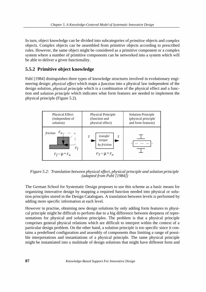
Chapter 5. A Knowledge-Centered Model of Systematic Innovative Design
87 Knowledge-Based Support For Innovative Design
In turn, object knowledge can be divided into subcategories of primitive objects and complexobjects. Complex objects can be assembled from primitive objects according to prescribedrules. However, the same object might be considered as a primitive component or a complexsystem where a number of primitive components can be networked into a system which willbe able to deliver a given functionality.
5.5.2 Primitive object knowledge
Pahl [1984] distinguishes three types of knowledge structures involved in evolutionary engi-neering design: physical effect which maps a function into a physical law independent of thedesign solution, physical principle which is a combination of the physical effect and a func-tion and solution principle which indicates what form features are needed to implement thephysical principle (Figure 5.2).
Figure 5.2: Translation between physical effect, physical principle and solution principle (adapted from Pahl [1984])
The German School for Systematic Design proposes to use this scheme as a basic means fororganizing innovative design by mapping a required function needed into physical or solu-tion principles stored in the Design Catalogues. A translation between levels is performed byadding more specific information at each level.
However in practise, obtaining new design solutions by only adding form features to physi-cal principle might be difficult to perform due to a big difference between deepness of repre-sentations for physical and solution principles. The problem is that a physical principlecomprises general physical relations which are difficult to interpret within the context of aparticular design problem. On the other hand, a solution principle is too specific since it con-tains a predefined configuration and assembly of components thus limiting a range of possi-ble interpretations and instantiations of a physical principle. The same physical principlemight be instantiated into a multitude of design solutions that might have different form and
Physical Effect(independent ofsolution)
Physical Principle(function and physical effect)
Solution Principle(physical principleand form features)
Ff = µ * Fn
Fn
Ff
frictiontransfertorque
by friction
FT = µ * Fn
T T

Chapter 5. A Knowledge-Centered Model of Systematic Innovative Design
Knowledge-Based Support For Innovative Design 88
material features but perform the same physical function. No references are proposed how toperform such instantiation either in Design Catalogues or in TRIZ. In other words, there is agap between physical and design views on the same object knowledge.
We believe that the problem can be overcome by introducing an intermediate knowledgestructure between the physical and solution principles - design concept. In addition to infor-mation on its physical structure, the design concept captures information on what technicalrequirements can be met by the physical principle and what generic form and material fea-tures are needed. A design concept is represented as a view of how specific aspects of theoverall behaviour of the physical principle can be related to engineering needs.
Summarizing, we believe that four layers of primitive object knowledge separated accordingto the degree of conceptualization should be distinguished for engineering design:
• fundamental physical laws,
• generic physical principles,
• generic design concepts,
• specific design descriptions.
Fundamental physical laws.
Knowledge of this layer expresses facts about the laws of nature in terms of relationsbetween two or more physical variables and describing under what conditions the relationsare valid. For instance, in classical physics, Newton’s second law F=ma establishes a relationbetween the variables of force and acceleration via the constant value of mass. A distinguish-ing feature of this type of knowledge is that it is independent of the design context. Thenecessity of separating this layer from others is obvious: this is a layer of fundamentalknowledge, and if we are interested in obtaining feasible solutions we must be able to checkevery new solution proposed by some procedure of design against its physical validity. Onthe other hand, if specific knowledge is obtained by instantiation of prior valid high-levelknowledge, the former automatically inherit the feasibility of the upper level.
Generic physical principles.
A generic physical principle is an instance of a more general physical law regarded withinthe context of what behaviour a system of physical components based on the law possesses.The generic physical principle is more specific than the fundamental knowledge since it rep-resents a system of physical components interacting under specific conditions. As a conse-quence, the behaviour of such a system might involve several relations based on severalphysical laws which are needed to provide the overall behaviour of the system. In addition toinformation presenting a behaviour of physical objects under specific conditions, the genericphysical principle includes a description of a physical function. In turn, the physical functionis a relation between two or more physical variables.
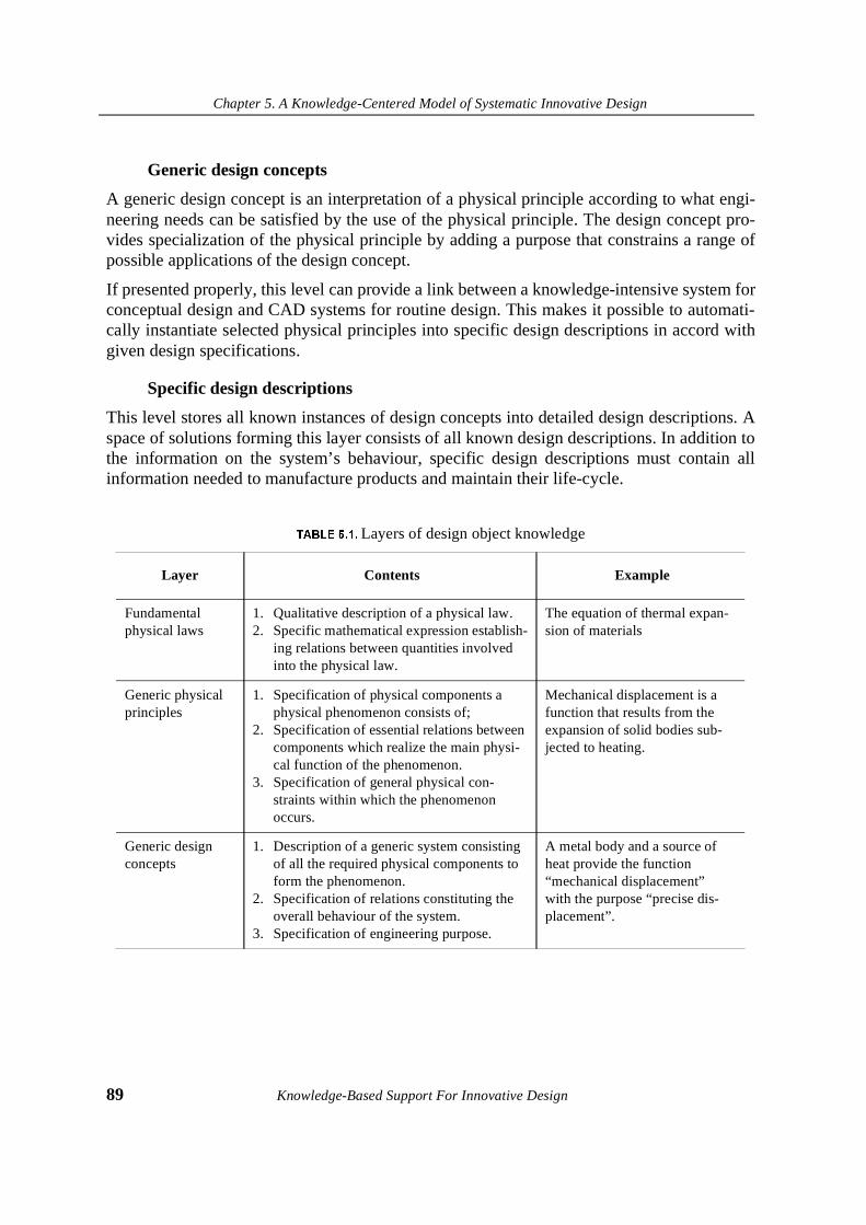
Chapter 5. A Knowledge-Centered Model of Systematic Innovative Design
89 Knowledge-Based Support For Innovative Design
Generic design concepts
A generic design concept is an interpretation of a physical principle according to what engi-neering needs can be satisfied by the use of the physical principle. The design concept pro-vides specialization of the physical principle by adding a purpose that constrains a range ofpossible applications of the design concept.
If presented properly, this level can provide a link between a knowledge-intensive system forconceptual design and CAD systems for routine design. This makes it possible to automati-cally instantiate selected physical principles into specific design descriptions in accord withgiven design specifications.
Specific design descriptions
This level stores all known instances of design concepts into detailed design descriptions. Aspace of solutions forming this layer consists of all known design descriptions. In addition tothe information on the system’s behaviour, specific design descriptions must contain allinformation needed to manufacture products and maintain their life-cycle.
7$%/(������Layers of design object knowledge
Layer Contents Example
Fundamental physical laws
1. Qualitative description of a physical law.2. Specific mathematical expression establish-
ing relations between quantities involved into the physical law.
The equation of thermal expan-sion of materials
Generic physical principles
1. Specification of physical components a physical phenomenon consists of;
2. Specification of essential relations between components which realize the main physi-cal function of the phenomenon.
3. Specification of general physical con-straints within which the phenomenon occurs.
Mechanical displacement is a function that results from the expansion of solid bodies sub-jected to heating.
Generic design concepts
1. Description of a generic system consisting of all the required physical components to form the phenomenon.
2. Specification of relations constituting the overall behaviour of the system.
3. Specification of engineering purpose.
A metal body and a source of heat provide the function “mechanical displacement” with the purpose “precise dis-placement”.
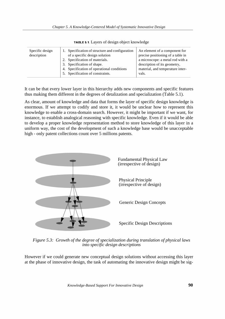
Chapter 5. A Knowledge-Centered Model of Systematic Innovative Design
Knowledge-Based Support For Innovative Design 90
It can be that every lower layer in this hierarchy adds new components and specific featuresthus making them different in the degrees of detalization and specialization (Table 5.1).
As clear, amount of knowledge and data that forms the layer of specific design knowledge isenormous. If we attempt to codify and store it, it would be unclear how to represent thisknowledge to enable a cross-domain search. However, it might be important if we want, forinstance, to establish analogical reasoning with specific knowledge. Even if it would be ableto develop a proper knowledge representation method to store knowledge of this layer in auniform way, the cost of the development of such a knowledge base would be unacceptablehigh - only patent collections count over 5 millions patents.
Figure 5.3: Growth of the degree of specialization during translation of physical laws into specific design descriptions
However if we could generate new conceptual design solutions without accessing this layerat the phase of innovative design, the task of automating the innovative design might be sig-
Specific design description
1. Specification of structure and configuration of a specific design solution
2. Specification of materials.3. Specification of shape.4. Specification of operational conditions5. Specification of constraints.
An element of a component for precise positioning of a table in a microscope: a metal rod with a description of its geometry, material, and temperature inter-vals.
7$%/(������Layers of design object knowledge
Fundamental Physical Law
Physical Principle
Generic Design Concepts
Specific Design Descriptions
(irrespective of design)
(irrespective of design)
Chapter 5. A Knowledge-Centered Model of Systematic Innovative Design
91 Knowledge-Based Support For Innovative Design
nificantly simplified. Hence, to organize reasoning about existing design concepts in order tobe able to generate new solutions one has to codify all information at the layer of conceptualdesign knowledge. This layer stores significantly less data.
It is important that objects stored at the layers of generic knowledge must not be separated bydomain features. We believe that such separation creates barriers to the use of previouslyused physical principles within a new context. As follows from a TRIZ interpretation ofinnovative design, this layer is most important for organizing the search for innovative solu-tions through high-order knowledge transfer over domains.
Apart from a better understanding of how knowledge for design is to be organized, the divi-sion between knowledge layers proposed provides an explanation of discovery, inventionand innovation at a knowledge level:
1. A solution satisfying the given requirements is known and available at the level ofgeneric design concepts. It can be selected and adapted to meet the requirements bya routine design procedure or synthesized from existing design objects. This situa-tion results in innovative solutions.
2. No design object which is a solution to the problem is available. However, it can begenerated by instantiating existing fundamental knowledge or physical principlesinto a new design object. Such type of design results in inventions.
3. No physical knowledge is available to meet the given requirements. This situationindicates that requirements should be reformulated otherwise a new scientific dis-covery at the level of fundamental physical knowledge is required to solve the prob-lem.
5.5.3 Complex object knowledge
It is a rare case when a specific design description only utilizes a single physical effect. Themajority of new specific design descriptions as well as generic design concepts consist ofcombinations of several objects. In many cases, to meet a new requirement is not possible bydirectly mapping the function given onto a single physical principle. To perform well, thesystem must have a source of energy and deliver some auxiliary functions to provide therequired performance of system’s main function.
A criterion which can be defined for dividing between primitive and complex objects is com-plexity. Similarly to knowledge deepness, complexity is a subjective factor and it may onlybe regarded with respect to a predefined level of system decomposition. For instance, a phys-ical phenomenon of thermal expansion might be regarded as a primitive object whereas forother purposes, the same phenomenon can be decomposed into more primitive objects suchas phenomenon of heat transfer, phenomenon of molecular movement and so on.
In engineering design, a concept of object complexity plays an important role in organizingbottom-up and top-down models of design process. Any design product can be represented

Chapter 5. A Knowledge-Centered Model of Systematic Innovative Design
Knowledge-Based Support For Innovative Design 92
as a set of interrelated primitive objects. Vice versa, primitive objects can be arranged andrelated in such a way that a resultant composition of objects is a new design product.
Figure 5.4: A knowledge-intensive model of innovative design
3UREOHP
GHFRPSRVLWLRQ�RI�LQLWLDO
�GHVLJQ�VSHFLILFDWLRQV
3UREOHP�PRGHOOLQJ
PDSSLQJ�IXQFWLRQ
RQWR�JHQHULF�GHVLJQ
FRQFHSW
JHQHUDWLRQ�RI�FRPSOH[
JHQHULF�GHVLJQ�FRQFHSW
LGHQWLILFDWLRQ
RI�D�W\SH�RI�
SUREOHP�PRGHO
LGHQWLILFDWLRQ�RI
D�VROXWLRQ�SDWWHUQ
WUDQVIRUPDWLRQ�RI
D�JLYHQ�SUREOHP�
PRGHO�LQWR�D�VROXWLRQ
GHILQLQJ�D�IXQFWLRQ
RI�QHZO\�LQWURGXFHG
FRPSRQHQWV
FKHFN�DJDLQVW�ERXQGDU\
FRQGLWLRQV
FKHFN�DJDLQVW�
FRQVWUDLQWV�JLYHQ
PRGHO
substance-fieldmodel
function
LQQRYDWLYH�VROXWLRQ�
LGHQWLILFDWLRQ�RI�
SUREOHP�W\SH
3UREOHP�PRGHOOLQJ
contains contradiction lack of knowledge
PDSSLQJ�IXQFWLRQ
RQWR�JHQHULF�SK\VLFDO
SULQFLSOH
FKHFN�DJDLQVW�ERXQGDU\
FRQGLWLRQV
FKHFN�DJDLQVW�
FRQVWUDLQWV�JLYHQ
LQYHQWLYH�VROXWLRQ�
FRQFHSW FRQFHSW
Chapter 5. A Knowledge-Centered Model of Systematic Innovative Design
93 Knowledge-Based Support For Innovative Design
Summarizing, complex knowledge can be: i) decomposed into primitive objects to performsystem analysis ii) synthesized from primitive objects to perform system synthesis.
5.5.4 Object knowledge base
Both primitive and complex object knowledge might be represented in KBS independentlyof the inference mechanism and strategic knowledge. Therefore, a knowledge base usingclasses, objects and relations between them might be sharable between various applications,such as diagnosis, generation of explanations, etc.
One of the INDES goals is to provide a theoretical framework for building a knowledge baseof object knowledge for conceptual design. We argue that such a knowledge base shouldconsist of at least two knowledge layers: a layer of generic physical principles and the layerof generic design concepts to obtain innovative and inventive design solutions respectively.A general modelling framework, knowledge representation methods and knowledge basecontents will be presented in detail in chapter 6.
A similar approach to structuring design knowledge is used by several research projectsworldwide which are trying to build knowledge bases which would be able to store physicalfeatures of design objects. For instance, a KBS based on qualitative process theory anddeveloped at the University of Tokyo will contain 10.000 chunks of knowledge (Tomiyamaet al. [1994]). Similar efforts are being undertaken at Stanford University within the project“How things work” for building a knowledge base of physical devices used in engineeringdesign and diagnosis (Iwasaki et al. [1993]).
5.6. Strategic knowledge for conceptual design
In general design theory (Yoshikawa [1981], Tomiyama et al. [1987]), a design is consideredas mapping from the functional space where design specifications are described in terms offunctions onto the attribute space where design solutions are presented in terms of exactattributes. In innovative design, this mapping may not be realized directly since no designsolution in terms of exact attributes is available before the mapping. Innovative designinvolves an evolutionary process: functional space is first mapped onto conceptual designspace and only then conceptual attributes can be instantiated into specific attributes.
The role of strategic knowledge is to organize a reasoning process with object knowledgeand task knowledge. A strategy can be derived from a general model of the problem solvingprocess. In turn, the strategy defines what problem-solving strategy a KBS should be able torespond with to a particular problem.
Based on a study of TRIZ, we recognize the following groups of strategic knowledge forconceptual design:
Chapter 5. A Knowledge-Centered Model of Systematic Innovative Design
Knowledge-Based Support For Innovative Design 94
1. Meta-level rules defining what particular reasoning strategy is to be used.
2. Principles for handling ill-defined initial design specifications available at the phaseof inventive design and decomposing them into specifications recognisable by prob-lem-solving.
3. Principles for mapping obtained specifications onto generic design concepts orgeneric physical principles.
4. Principles for the synthesis of alternative design concepts.
5. Principles for the evaluation and selection of the best design concept.
5.6.1 An integrated model of innovative design
Before we present an overview of strategic knowledge for innovative design, we would liketo present a model of a design process we developed within INDES. The INDES designmodel is derived from the knowledge-centered model of innovative design, described in sec-tion 5.4.
Two types of designs are possible: design as synthesis and design as problem solving.Despite successful application within industries, this model incorporates a significant disad-vantage if we want to build a KBS upon it: after working with Inventive Principles or Inven-tive Standards, we do not obtain a solution in terms of exact physical components to beintroduced into the existing design or how the design has to be physically changed. Onlyabstract models of solutions are available.
Therefore we believe, that a solution concept obtained after design process must be repre-sented as a design object in terms providing reference to what physical components are to beused no matter what problem solving strategy has been selected.
Another problem is caused by knowledge inconsistency. As follows from the analysis weconducted on TRIZ problem solving techniques, it would not be possible to model and repre-sent engineering contradictions in a formal way if the formulations available in TRIZ wereused. The principles for the elimination of engineering contradictions are very general andthey are not intended to operate in terms of specific problems. On the other hand, the com-parison of Inventive Principles and Inventive Standards revealed that the latter represent con-tradictions implicitly. Also solutions resulting from Inventive Standards are of higher qualitysince Inventive Standards are able to eliminate both physical and engineering contradictions.As a conclusion, Inventive Standards are able to cover the whole class of innovative prob-lems which could be solved by Inventive Principles and there is no need to model bothInventive Principles and Inventive Standards.
To eliminate the above mentioned disadvantages, we have decided to combine both modelsof design into an integrated model of knowledge-intensive design shown in Figure 5.4. Achoice of strategy for problem solving is defined after decomposing the initial design specifi-cations. If this decomposition results in the necessity to change the existing design product

Chapter 5. A Knowledge-Centered Model of Systematic Innovative Design
95 Knowledge-Based Support For Innovative Design
then a solution model can be obtained by applying Inventive Standards. Then, a function ofnewly introduced or modified components has to be defined to identify specific substancesand fields. However, if the designer lacks knowledge of how to deliver the function, a directmapping of the function onto existing generic object knowledge has to be performed.
5.6.2 Meta-level strategy
The meta-level strategy determines what type of inference will be relevant to solve a particu-lar problem. As follows from previous discussion, after a decomposition of IDS, the designcan proceed in two ways: transformation of the existing system or direct mapping of thefunction given onto generic object knowledge.
Summarizing, meta-level strategy rules are used to:
• evaluate what type of problem is specified;
• determine what type of problem model results from the decomposition of IDS;
• determine what problem-solving strategy and what knowledge sources are to beused to organize an inference with respect to a particular problem.
5.6.3 Initial design specifications
One of the disadvantages of a product-oriented approach to design process is that the qualityof the obtained products depends solely on the validity and completeness of the input specifi-cations. For this reason, getting the “right” specifications becomes a difficult task. It is com-mon in different areas of engineering design that specifications of a product to be designedare expressed in the form of functions the product has to deliver, values of parameters of thefunctions and various constraints restricting possible design variants. As mentioned in chap-ter 2, exact functional specifications might not be available at the phase of innovative design.However, no design process is possible without defining the functionality of a future product.
To obtain a problem model expressed in the form of functional specifications, we believethat a technique for obtaining functional specifications from general problem formulationshas to be developed. In INDES, we distinguish between several levels of initial design speci-fications (IDS), where the upper level contains commonsense expressions reflecting ourwishes and desires, and the lower level contains functional specifications which can providean adequate reference to some generic physical principle or design concept stored in aknowledge base.
Summarizing, the principles for IDS decomposition aim at coming up with two possibleproblem models:
• a function identifying a physical action with respect to some material component orphysical field;

Chapter 5. A Knowledge-Centered Model of Systematic Innovative Design
Knowledge-Based Support For Innovative Design 96
• a substance-field model of a physical system where undesired interaction betweencomponents implicitly indicates a contradiction.
5.6.4 Problem modelling and problem solving
This type of knowledge defines a procedure of mapping between the specifications obtainedafter IDS decomposition and generic physical principles or design concept(s) available in theobject knowledge base.
Problem modeling rules are defined on the basis of Inventive Standards. They are designatedto specify a procedure for building correct and consistent models of design products thathave to be improved but might not be since any attempt to make a change leads to a contra-diction. A collection of Inventive Standards proposes specific patterns of solutions expressedin the form of black-box components. Therefore, a principal requirement is that a problemmodel must be formulated in terms adequate to the solution patterns.
Object knowledge presenting a design product that should be changed (design prototype, inother words) is defined as task knowledge in INDES. Task knowledge represents a descrip-tion of a design prototype. The role of task knowledge is to provide a KBS with core infor-mation on a problem to be solved. A way of modelling and representing task knowledge issimilar to the way of representing generic design concepts. The suitability of these represen-tations makes it possible to reason about task knowledge in terms of task-independent objectknowledge stored in a knowledge base of generic physical principles and design concepts.
After selection of an appropriate pattern, a solution is presented in terms of “empty” compo-nents introduced into the model of a design product. A specific-task instantiation of “empty”components into conceptual design solutions is provided by finding what material compo-nents and energy flows (physical fields) that constitute physical principles are capable ofdelivering a function specified for a “blank” component. The applicability of a selected phys-ical principle is then verified by checking against boundary conditions between existingcomponents of a design prototype and the components to be introduced.
5.6.5 Design concept generation
Provided that a problem model is expressed in terms of exact functions, two situations arepossible after mapping functional specifications onto object knowledge:
1. The object knowledge completely meets functional specifications. Depending onwhat level object knowledge has been found, physical or design, a specific designsolution might be evolved from a set of abstract descriptions into a set of more con-crete descriptions.
2. The object knowledge partly meets the functional specifications. In this case, a com-plex design concept has be generated from predefined primitives - generic physicalprinciples or generic design concepts. The rules for new design concept synthesis
Chapter 5. A Knowledge-Centered Model of Systematic Innovative Design
97 Knowledge-Based Support For Innovative Design
define a procedure for how relevant primitives are selected and combined into com-plex structures and what optimization methods exist to come up with an optimalconcept.
We must note, however, that evolving the specific design description from generic designknowledge is not part of INDES. Therefore, the output of the design process performed withthe INDES-based KBS results in the description of a primitive generic knowledge in the firstcase. The output in the second case is a complex generic design concept.
5.7. Summary
In this chapter, we presented a knowledge-centered model of innovative engineering designthat emerged from studying Altshuller’s approach and the TRIZ knowledge repository froma knowledge-based point of view. Based on this model, we distinguished and gave a briefoverview of object and strategical knowledge that might be incorporated into a knowledgebased system supporting innovative design.
We explained a difference between concepts of discovery, invention and innovation at aknowledge level since it is important for better understanding of how to structure knowledgefor innovative design.
To make a model of innovative design more consistent, it is proposed to build an integratedmodel of innovative design allowing for both design as synthesis and design as problem solv-ing to be supported by the same knowledge sources.
In the next chapters we will present both object and strategical knowledge in detail. We willalso explain a framework for modelling and representing object knowledge for design in anuniform way based on an ontological approach.

Knowledge-Based Support For Innovative Design 98

Chapter 6. INDES: An ontological approach to modeling object knowledge.
99 Knowledge-Based Support For Innovative Design
Chapter 6. INDES: An ontological approach to modeling object knowledge.
6.1. Introduction
In supporting knowledge-intensive human activities, such as engineering design, AI systemscapable of reasoning with a large diversity of knowledge provide better results compared tosystems based on a narrow, domain-specific method. Such systems usually incorporate vari-ous different knowledge representation methods allowing for modeling knowledge with dif-ferent degrees of abstraction and completeness. This requires communication betweenvarious knowledge sources. As a consequence, the development of such systems using tradi-tional AI approaches, for instance, rule-based technology together with relevant techniquesfor knowledge acquisition, would be very complex, costly and time-consuming.
Over a few recent years, the ontological approach has played an increasingly important rolewith tackling the problem of describing knowledge domains. In general, the ontologicalapproach belongs to a branch of philosophy concerned with what really exists as opposed towhat appears to exist but does not. An ontology is the set of real objects or events the theoryconsists of described by referring to them without reference to an observer.
However, in AI, an ontology has slightly different meaning. The ontology is used to intro-duce a set of fixed concepts thus enabling factual information about domain to be modeled inuniform way. The ontology is separated from a knowledge representation method. Such sep-aration makes it possible to make knowledge concepts presented within the same ontology tobe sharable between different application frameworks. In AI, to create a domain ontology
Chapter 6. INDES: An ontological approach to modeling object knowledge.
Knowledge-Based Support For Innovative Design 100
means to perform knowledge categorization and conceptualization and to establish explicitrelations between domain knowledge concepts.
As we pointed in Chapter 2, ontologies are especially useful for representing knowledgecomponents of very large domains or metaknowledge that can be generalized over severalspecific domains. With respect to engineering design, massive research efforts are beingundertaken at the University of Tokyo, where a collection of ontologies has been developedto create a Knowledge-Intensive Engineering Framework (Tomiyama et al. [1994], Ishi et al.[1995]). Similarly, in the Knowledge System Laboratory of Stanford University, a collectionof ontologies has been developed for design knowledge representation, sharing and reuse(Gruber et al. [1992], Gruber & Olsen [1994]).
Development of the ontology is a necessary step for organizing innovative design based onsharable physical knowledge. While in the previous chapter we discussed a role of objectknowledge for organizing knowledge-centered innovative engineering design, in the presentchapter the INDES ontology aimed at modeling object knowledge for conceptual engineer-ing design is presented. The role of INDES is twofold: first it introduces a fixed set of con-cepts allowing for uniform modeling of exiting design products, and second, the same set ofconcepts is used to design new product concepts.
TRIZ Pointer to physical effects (PPE) presented in Chapter 3 has proven to be effective insupporting innovative engineering activities. Knowledge stored in PPE can be viewed as auseful collection of factual information. On the other hand, the way in which design knowl-edge is organized and represented is a critical factor in the computer-supported design proc-ess. We therefore defined the task of INDES as the provision of a framework forrestructuring, reorganizing and modeling knowledge stored in PPE. To achieve this, we usethe ontological approach.
The chapter is organized in the following way: first, we present a critique of TRIZ approachto modeling physical knowledge; second, basic INDES concepts for modeling generic physi-cal knowledge are discussed; and in the end, we illustrate our approach by several examplesof modeled physical phenomena and generic design concepts.
6.2. INDES modeling framework
6.2.1 Physical knowledge and System Theory
The vast majority of designers refer to three types of information sources when designingnew product concepts: physical handbooks, engineering handbooks and previous design doc-umentation (or patent descriptions). While physical handbooks and encyclopaedia single outgeneric properties of interacting physical entities and present them in terms of quantitativelyrelated variables and constants, engineering handbooks describe specific relationshipsbetween technical parameters of ready-to-use solutions. In addition, previous design docu-

Chapter 6. INDES: An ontological approach to modeling object knowledge.
101 Knowledge-Based Support For Innovative Design
mentation presents every aspect of a specific solution. Such organization of previous knowl-edge makes finding the right conceptual description of design product or concept within alarge mass of information difficult if not impossible.
Therefore, structured collections of generic building blocks, presented in the form of concep-tual design primitives could be of great help to the designers. The task of creating such col-lections addresses the task of conceptual modeling since accurate representation of everyaspect of mechanical, electrical and other types of systems in a uniform way does not seem tobe possible.
For this reason, our attention was drawn to the question: how can kinematic, electronic andother types of conceptual models widely used in engineering be presented in such way so thatvarious domain-specific principles could coexist in the same diagram regardless of thedomains used? What degree of conceptualization is necessary to provide sharability of themodels and their compatibility to synthesise new design concepts from such models? Theanswer to this question requires a modeling method that will allow every physical effect andphenomenon to be presented in a uniform way.
Modeling is a key concept in problem solving. A large part of the difficulty of a computer-aided problem solving process is due to the difficulty of selecting an adequate modelingmethod and building a proper problem model. With respect to engineering design, oneknown framework which allows for such modeling are Bond Graphs. However, we believethat to present information on energy transformations is not sufficient. Although any trans-formation of matter can be expressed through a change of energy, we argue that both types oftransformations should be presented explicitly. If a functional requirement is formulated as“to vary electrical resistance”, it may not be directly mapped onto an energy transformationprinciple since the requirement defines an operation with strictly material property. Hence,the first motivation for developing INDES was therefore ability to model information onmaterial transformations.
The second motivation behind developing INDES was that when targeting at domain-inde-pendent computer-aided innovative design, a proper modeling framework should not bedependent on a particular problem-solving method. For this reason, models should explicitlyincorporate the generic features of physical systems which are important for any type ofproblem-solving process in conceptual engineering design. Such independence can be pro-vided by using the ontological approach to modeling knowledge.
Among a number of existing theoretical backgrounds for developing ontologies for concep-tual design, our opinion has been that System Theory and network modeling is best suited forour task (Shearer et al. [1967], Martin & Allen [1969]). A major advantage of System Theoryis that it regards entities of the physical world as systems and proposes adequate tools forestablishing mathematically accurate relations between the physical entities.
System Theory also provides tools for the correct modeling of systems which belong to dif-ferent domains. Apart from mathematical accuracy, representing different physical effectsand phenomena in terms of systems gives the possibility to instantiate high-order system

Chapter 6. INDES: An ontological approach to modeling object knowledge.
Knowledge-Based Support For Innovative Design 102
models into more specific solution models, and to check against the feasibility of resultedmodels at very early stages of design. Therefore, INDES is intended for modeling of allknown physical phenomena and effects in terms of systems by using common ontologicalconcepts.
6.2.2 Macroscopic and microscopic observations
A complexity of modeling is related to, at least, two factors:
1. Degree of detalization which defines how deep modeling is performed.
2. Assumptions which define what information can be omitted during modeling since ithas no influence on the use of the resulting model.
There are at least two relative levels of detalization at which the modeling of a physical phe-nomenon might be performed: microscopic and macroscopic. Take, for instance, the effect ofJoule heat: generation of heat as a result of passing an electrical current through a conductivematerial. In this case, modeling at the microscopic level implies establishing relationshipsbetween energy characteristics of migrating electrons and the general increase of internalenergy of the material. To model the effect under macroscopic observations means that firstwe have to make a decision on what information is crucial to achieve the externally observedresult. In terms of System Theory, we have to establish the relation between the change ofelectrical energy and thermal energy generated, and to specify what parameters are involvedin the relation. Information on internal processes can therefore be of no interest to thedesigner and is thus hidden inside a black box.
The latter way of modeling gives no clear understanding what internal physical processescause the effect. Instead, it indicates what is needed to obtain the required result and how achange of energy and material properties can be used practically. In that case, the microlevelphysical processes can be modeled as a black box. More detailed explanation of how mode-ling is performed on the basis of the effect of Joule heat will be given in section 5.6.1.
A black-box approach to modeling may not be identified with absolutely precise modeling. Itdoes provide, however, information enough for organizing a reasoning process with modeledknowledge which is needed to generate new solution concepts. We can argue that such ideal-ized models are the best way to represent information on various domains in a uniform way.Therefore, a choice of the level of detalization defines the degree of the ideality of the model.
6.2.3 Requirements for a model of physical phenomena
Given System Theory and network modeling as theoretical backgrounds, we formulated thefollowing requirements for a conceptual model of physical effects and phenomena:
1. A physical effect has to be modeled as an abstract, simplified concept of a systemproviding context-independent semantics.
Chapter 6. INDES: An ontological approach to modeling object knowledge.
103 Knowledge-Based Support For Innovative Design
2. The model has to be generic with respect to possible specific solutions that might beobtained on the basis of the model.
3. The model has to explicitly incorporate all the necessary information which estab-lishes relations between inputs and outputs of the system.
4. The model must be mathematically correct with respect to the chosen modelinglevel and not violate physical laws.
5. The model has to include constraint information to enable calculating quantitativevalues of input data when the output data is given and output data when the inputdata is given respectively.
6.2.4 YMIR: a sharable ontology for modeling design knowledge
As a basis for modeling generic physical knowledge for innovative design according to therequirements formulated above, we use YMIR -- a sharable ontology for modeling designknowledge in a uniform way. YMIR was developed in the Knowledge-Based Systems Groupof the University of Twente (Alberts [1993]). YMIR defines a taxonomy of concepts for theformal description of design knowledge in different domains. The concepts in YMIR for theelements from which to synthesize technical system descriptions are labelled “generic sys-tem models” (GSM). These generalized concepts have been defined in terms of networkmodels in System Theory. Generic system models explicitly incorporate the relation betweenfeatures of an engineering system such as behaviour and form.
YMIR distinguishes multiple levels of abstraction with corresponding sets of generic systemmodels. The result allows for the gradual refinement of the design description at levels rang-ing from the original problem specification to the final artifact description. The resulting col-lection of knowledge structure concepts makes it possible to systematically organize theknowledge to support its reuse. The advantage of YMIR is that the modeling framework isapplicable to all domains in which technical systems can be described as system-theoreticalnetwork models.
Whereas Bond Graphs are limited to modeling energy aspects of systems, YMIR enablesmodeling form properties of systems. Using material and geometrical aspects of designs tomodel their behaviours makes it possible to incorporate necessary information on materialproperties of designs. This claim is important since, in many situations, the initial keyrequirements are formulated in terms of parameters of material components. As a conse-quence, the requirements can not be directly expressed in terms of energy transformationswithout knowing what effect is able to meet these requirements.
Chapter 6. INDES: An ontological approach to modeling object knowledge.
Knowledge-Based Support For Innovative Design 104
6.3. INDES Concepts
6.3.1 Physical Components
The INDES ontology defines two sets of concepts: concepts for modeling physical compo-nents and concepts for modeling the relations between the physical components. Among theconcepts presenting the physical components in INDES are: material component, energyflow, generic physical principle and generic design concept. By introducing these concept,INDES covers the whole class of physical entities and generic systems that exist or can beobtained from more primitive components.
A generic design concept consists of a number of more primitive components such as mate-rial components and energy flows.
Definition 6.1.
Material component is an idealized physical object possessing mass, propertiesof materials and occupying space. We distinguish between lumped and distrib-uted components (such as solid, gas or liquid).
A material component is an object modeled under the assumption that it may not be decom-posed into more primitive components.
Definition 6.2.
Energy flow is an idealized flow of energy either spatially oriented or distributedin space.
In general, the energy flow might be represented through physical parameters both in vectorand scalar forms. In INDES, we use scalar form. Similarly to the material component, theenergy flow is an idealized component which may not be decomposed into more primitivecomponents.
The material components and energy flows can be composed into a generic physical princi-ple which is a central concept of INDES.
Definition 6.3.
Generic Physical Principle is a spatial arrangement of material components andenergy flows that results in continuous or discrete change of parameters identi-fied with an energy flow or material component for the time given.
Analogously, generic physical principles can be composed into a more complex structurelabelled the Generic Design Concept. The generic design concept is a model of a final designproduct or some part that interacts with the environment or other systems and fulfils a practi-cal purpose.
Chapter 6. INDES: An ontological approach to modeling object knowledge.
105 Knowledge-Based Support For Innovative Design
Definition 6.4.
Generic Design Concept is a physically valid network of generic physical prin-ciples arranged in a predetermined way and which achieves a purpose specifiedby design specifications.
Formally, a generic design concept is a tuple DC = <SF , EF , P>, where SF is a set of physi-cal phenomena occurring within a system, EF is a set of relations between phenomena, and Pis the purpose(s) of the design product.
A detailed description of modeling both generic physical principles and generic design con-cepts will be presented further in this chapter after definition of concepts for establishingrelations between the physical components.
6.3.2 Relations: behaviour and function
Physical effects result from specific spatial and temporal arrangements of material compo-nents and energy flows. When arranged in a specific manner and provided that there is a timeinterval, the physical components interact with each other. Such an interaction results in achange of certain parameters identified with the objects. An ontological concept for present-ing such changes over the time by specifying the relations between the objects is behaviour.A system’s behaviour serves as a means to:
1. Establish the relations between system parameters involved into description of thephysical components comprising physical principles.
2. Provide a mapping of functional specifications onto a physical system that is capa-ble of meeting the specifications.
A behaviour specifies how a system works by specifying relationships between the compo-nents of the system. These relationships specify how a system’s components interact witheach other according to an external change. As components of the system may posses theirown behaviour, the overall system’s behaviour might be decomposed into more specificbehaviours.
Before giving definitions of behaviour and function, we must analyse how these two con-cepts are interrelated. This analysis is important since no common agreement has beenachieved in AI in Design on what is dominant: function or behaviour.
A study of the literature shows that discussions rise about the relative places of function andbehaviour because of two different interpretations of the concept of function. The first pointof view is widely accepted in the design community which defines a function as a relation-ship of input and output material, energy or information and was introduced by Rodenacker[1971]. On the basis of his definition, Koller [1976], Roth [1982] and Krumhauer [1974]introduced sets of so-called “elementary functions” that might be used for modeling of anytype of physical system in terms of energy-transforming components.
Chapter 6. INDES: An ontological approach to modeling object knowledge.
Knowledge-Based Support For Innovative Design 106
Within such approach, a behaviour of a system is defined as a combination of such elemen-tary functions. However, there is still no common agreement between designers as to whichset of elementary functions to use (van den Kroonenberg & Siers [1996]).
A totally different approach defines function as an expression of the designer’s intent(s)regardless of physical or informational semantics. Value Engineering, for instance, defines afunction in the verbal form “to do something” (Miles [1972], Litvin & Guerassimov [1991b],Sasajuma et al. [1995], Kowalick [1996]). Under this view, function is represented as a ver-bal expression of what an object, which is a part of a system, is supposed to do with respectto other system components. Therefore, such function as “to prevent an aircraft from shak-ing” is correct in Value Engineering.
As a conclusion, without prior commitment on a context in which the word “function” isunderstood, its use might be misleading. From our point of view, the ambiguity of definitionsfor function and behaviour observed within the different AI and Design schools is an attemptto use the same word to describe both physical processes occurring in the system and theirinterpretation in the form of a designer’s intents. However, the designer’s intents, and, as aconsequence, functions formulated as the intents might have nothing to do with the physicalcontext.
To eliminate this ambiguity, we argue that it is important to distinguish between two viewsunder which any artificial system might be viewed: physical-oriented and solution-oriented.These two views define different concepts which can be used to model both informationabout physical processes occurring in the system and the expression of the designer’s intents.Under a physical-oriented view, function specifies how two physical entities are related, thatis, an unambiguous, reproducible relationship between input and output. For instance, itmight be a relation between heat and electrical resistance as well as between temperature dif-ference and a mechanical displacement with an exact specification of all variables participat-ing in the relations. Therefore, our notion of a physical function is similar to the one used inclassical mathematics, but in the context of specific physical parameters.
A solution-oriented view interprets such relations from the particular point of view of adesigner. Usually such functions are expressed in a qualitative or verbal form. In that case,function can be regarded as an abstract interpretation of the relation between two physicalparameters regardless what physical parameters participate in the relation. For instance, if afunction is expressed as “to cool an object”, it may refer to a multitude of physical phenom-ena that can be used to change the object’s temperature.
To avoid confusion between the various interpretations of the term “function”, we proposedto call a solution-oriented view of a physical function a technical function. The technicalfunction therefore is a task-oriented, qualitative interpretation of the relation between twophysical parameters under a certain context expressing a designer’s intent. Observing thesystem from a physical point of view, we can define behaviour and function as two physicalproperties of the system which are independent of the engineering context.
Chapter 6. INDES: An ontological approach to modeling object knowledge.
107 Knowledge-Based Support For Innovative Design
For instance, the physical function of heat transfer T = f (H) does not specify itself if the tem-perature grows or drops unless the sign of dynamic change of heat flow is taken into consid-eration. Therefore, the technical function “to cool the object” is a particular interpretation ofthe function of heat transfer and is an instance of a more general physical function.
Since we agreed that we should regard physical function as a specific occurrence of anenergy transformation process within a system, we will define the physical function as amathematical relation between input and output energy flows.
Definition 6.5.
Physical function specifies a particular relation between input and output of asystem presented in the form of energy flows.
Formally, physical function can be defined as a tuple F = < P1, P2 >, where P1, and P2 aretwo related physical parameters describing energy flow, and P1 = f(P2).
Note that physical function1 itself only indicates a type of relation between parameters with-out specifying constraints on parameters participating in the relation. For this reason, thesame function can produce multiple behaviours. In Alberts [1993], two types of functions areintroduced: generic and specific. A generic function constrains the values of parameters to alimited set of intervals, whereas a specific function constrain the values of the parameters toone particular interval. When modeling existing design prototypes with INDES concepts, wewill use the concept of specific function.
A specific function can be further decomposed into subfunctions. Subfunctions are needed toclarify the representation of specific aspects of the physical process behind the physical phe-nomenon. Decomposition of the function into subfunctions is important to analyse problemsto reveal a specific role of individual components. On the other hand, explicit reference tosubfunctions provides mapping not only between functional specifications presented in termsof energy transformations but in terms of material transformations as well. There are twotypes of subfunctions in INDES:
1. A subfunction which defines how a material parameter depends on a change ofenergy flow for the time given: PM = f(PE in ) .
2. A subfunction which defines how a certain parameter of energy flow depends on amaterial parameter for the time given: PE out = f(PM).
To give a definition of behaviour we will assume that technical systems are specific instancesof generic physical systems considered in a particular engineering context. As described inprevious chapter, such instantiated systems can be modeled as a set of physical objects inter-acting with each other through energy and informational flows among the objects constitut-
1. Further in the text, we will refer to the physical function as “function” and the term “technical function” will be used explicitly
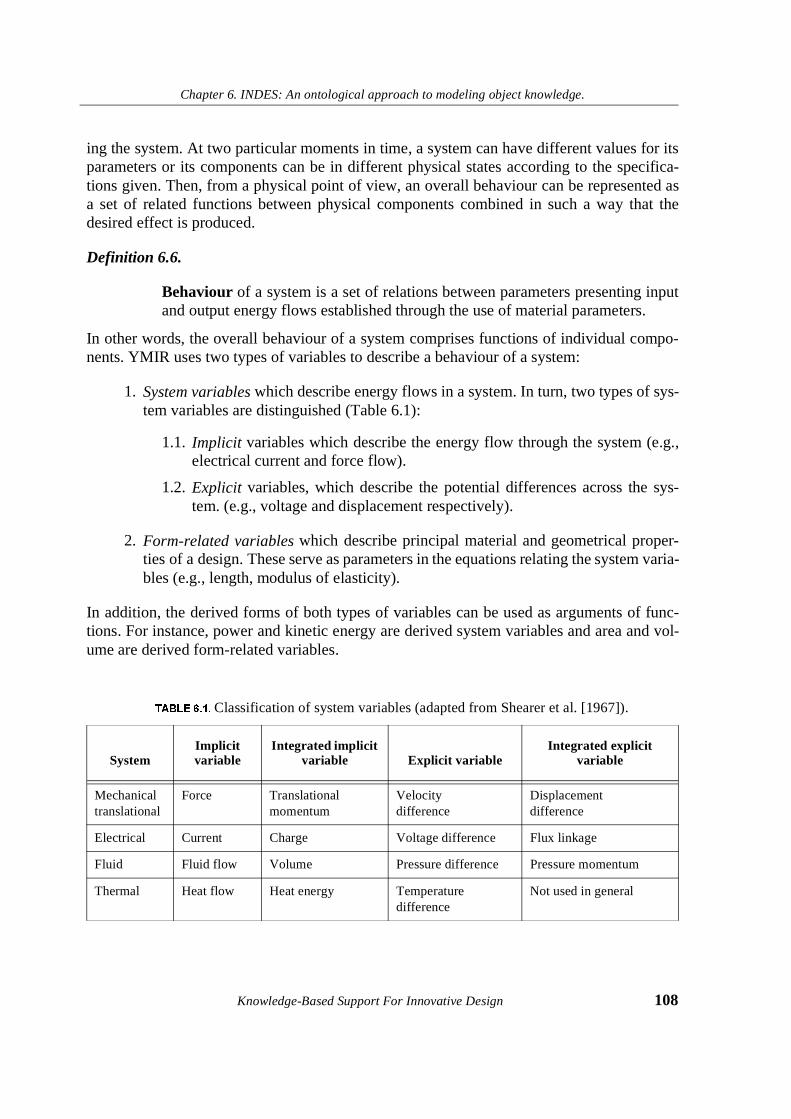
Chapter 6. INDES: An ontological approach to modeling object knowledge.
Knowledge-Based Support For Innovative Design 108
ing the system. At two particular moments in time, a system can have different values for itsparameters or its components can be in different physical states according to the specifica-tions given. Then, from a physical point of view, an overall behaviour can be represented asa set of related functions between physical components combined in such a way that thedesired effect is produced.
Definition 6.6.
Behaviour of a system is a set of relations between parameters presenting inputand output energy flows established through the use of material parameters.
In other words, the overall behaviour of a system comprises functions of individual compo-nents. YMIR uses two types of variables to describe a behaviour of a system:
1. System variables which describe energy flows in a system. In turn, two types of sys-tem variables are distinguished (Table 6.1):
1.1. Implicit variables which describe the energy flow through the system (e.g.,electrical current and force flow).
1.2. Explicit variables, which describe the potential differences across the sys-tem. (e.g., voltage and displacement respectively).
2. Form-related variables which describe principal material and geometrical proper-ties of a design. These serve as parameters in the equations relating the system varia-bles (e.g., length, modulus of elasticity).
In addition, the derived forms of both types of variables can be used as arguments of func-tions. For instance, power and kinetic energy are derived system variables and area and vol-ume are derived form-related variables.
7$%/(������Classification of system variables (adapted from Shearer et al. [1967]).
SystemImplicit variable
Integrated implicit variable Explicit variable
Integrated explicit variable
Mechanicaltranslational
Force Translationalmomentum
Velocity difference
Displacement difference
Electrical Current Charge Voltage difference Flux linkage
Fluid Fluid flow Volume Pressure difference Pressure momentum
Thermal Heat flow Heat energy Temperature difference
Not used in general

Chapter 6. INDES: An ontological approach to modeling object knowledge.
109 Knowledge-Based Support For Innovative Design
6.3.3 Structure.
To separate between two or more GPPs, their borders are denoted with the help of terminals,that is, ports for input and output energy flows. Therefore, a structure of the model is definedby a list of input and output ports.
Since we have chosen a black-box modeling approach, we will define two types of primitivecomponents: two-terminal GPP and multiterminal GPPs. An example of a two-terminal com-ponent is an electrical resistor when it is used to drop a voltage difference. According to theeffect of Joule heat, the same electrical resistor produces heat when an electrical currentpasses through it. Viewed from the position of both electrical and thermal domains the samephysical object can be represented as a GPP converting electrical energy into thermal energy.In this case, the model of the effect of Joule heat consists of four terminals. Another exampleof a our-terminal GPP is the piezoeffect: generation of a difference of electrical potential as aresult of mechanical displacement.
Definition 6.7.
Structure of the generic physical principle is a list of input ports where energyflow comes in and output ports where the energy flow comes out.
6.3.4 Constraints
Taking into consideration that each parameter which belongs to a real system must bedefined within a certain interval, or to have different discrete values during different states,all quantitative constraints on parameters can be described by the space of values. Given anyparticular moment in time, actual values of the parameters can be defined. Therefore, the fol-lowing notions are necessary to present numeric information constraining the system’sbehaviour:
l Generic space of values of system parameters: S = { PS1 ,..., P
Sn } ; where PS
i is arange of allowed values of energy or material parameter Pi. Two types of intervalsare possible: discrete and continuous intervals.
l Specific space of values system parameters at a given time: A = { PA1 ,..., P
An };
where PAi is an actual value of energy or material parameter Pi at a selected moment
of time.
These types of constraints represent information on a system through numeric intervals ordiscrete values of parameters under which the system’s behaviour corresponds to system pur-poses and meets all requirements. To represent dynamic aspects of a system we also need totake into account dynamic changes of variables specifying functions. If a static constraint isexpressed through interval values of parameters, then dynamic constraints specifies how a
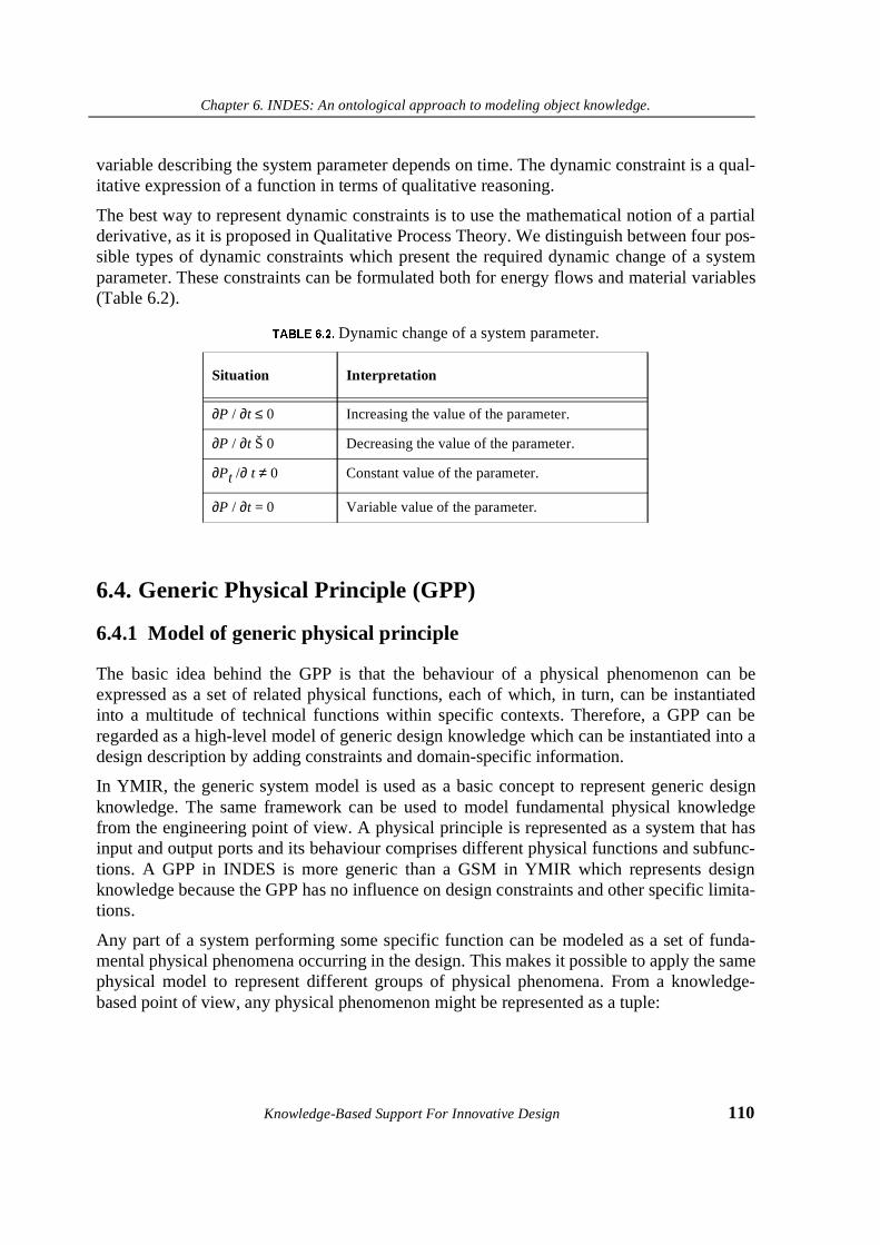
Chapter 6. INDES: An ontological approach to modeling object knowledge.
Knowledge-Based Support For Innovative Design 110
variable describing the system parameter depends on time. The dynamic constraint is a qual-itative expression of a function in terms of qualitative reasoning.
The best way to represent dynamic constraints is to use the mathematical notion of a partialderivative, as it is proposed in Qualitative Process Theory. We distinguish between four pos-sible types of dynamic constraints which present the required dynamic change of a systemparameter. These constraints can be formulated both for energy flows and material variables(Table 6.2).
6.4. Generic Physical Principle (GPP)
6.4.1 Model of generic physical principle
The basic idea behind the GPP is that the behaviour of a physical phenomenon can beexpressed as a set of related physical functions, each of which, in turn, can be instantiatedinto a multitude of technical functions within specific contexts. Therefore, a GPP can beregarded as a high-level model of generic design knowledge which can be instantiated into adesign description by adding constraints and domain-specific information.
In YMIR, the generic system model is used as a basic concept to represent generic designknowledge. The same framework can be used to model fundamental physical knowledgefrom the engineering point of view. A physical principle is represented as a system that hasinput and output ports and its behaviour comprises different physical functions and subfunc-tions. A GPP in INDES is more generic than a GSM in YMIR which represents designknowledge because the GPP has no influence on design constraints and other specific limita-tions.
Any part of a system performing some specific function can be modeled as a set of funda-mental physical phenomena occurring in the design. This makes it possible to apply the samephysical model to represent different groups of physical phenomena. From a knowledge-based point of view, any physical phenomenon might be represented as a tuple:
7$%/(������Dynamic change of a system parameter.
Situation Interpretation
∂P / ∂t ≤ 0 Increasing the value of the parameter.
∂P / ∂t Š 0 Decreasing the value of the parameter.
∂Pt /∂ t ≠ 0 Constant value of the parameter.
∂P / ∂t = 0 Variable value of the parameter.

Chapter 6. INDES: An ontological approach to modeling object knowledge.
111 Knowledge-Based Support For Innovative Design
where E is a set of energy parameters and M is a set of material parameters. As a conse-quence, GPP is a model of a system based on a specific physical phenomenon.
A GPP model has three parts:
• Behaviour: a set of relations between input and output energy flows.
• Form: list of material and geometrical parameters which determine the behaviour ofa GPP.
• Structure: lists of ports for input and output energy flows.
We distinguish between two categories of GPP:
• Homogeneous GPP: input and output flows are of the same type of energy (Figure6.1). Here, Cm is a particular physical property of a material which provides thechange of the energy flow E and the potential difference ∆A.
• Heterogeneous GPP: input and output energy flows are of different types of energy.The elements converting one type of energy into another are called transducers inSystem Theory (Figure 6.2). Here, Cm is a particular physical property of a materialwhich provides the transformation of an input energy flow of one type Ain into anoutput energy flow of another type Bout. ∆A and ∆B are explicit variables thatdescribe the potential differences across the system.
Figure 6.1: Graphical form of homogeneous GPP
Figure 6.2: Graphical form of heterogeneous GPP
Φ E M,⟨ ⟩=
Ain
Aout
∆A Cm
Bout
Bin
Ain1
Aout1
∆A ∆B
Cm
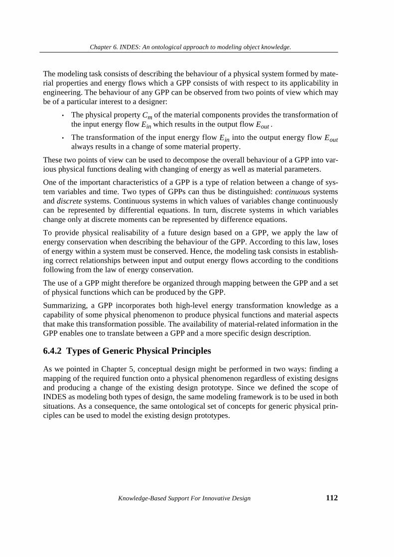
Chapter 6. INDES: An ontological approach to modeling object knowledge.
Knowledge-Based Support For Innovative Design 112
The modeling task consists of describing the behaviour of a physical system formed by mate-rial properties and energy flows which a GPP consists of with respect to its applicability inengineering. The behaviour of any GPP can be observed from two points of view which maybe of a particular interest to a designer:
• The physical property Cm of the material components provides the transformation ofthe input energy flow Ein which results in the output flow Eout .
• The transformation of the input energy flow Ein into the output energy flow Eoutalways results in a change of some material property.
These two points of view can be used to decompose the overall behaviour of a GPP into var-ious physical functions dealing with changing of energy as well as material parameters.
One of the important characteristics of a GPP is a type of relation between a change of sys-tem variables and time. Two types of GPPs can thus be distinguished: continuous systemsand discrete systems. Continuous systems in which values of variables change continuouslycan be represented by differential equations. In turn, discrete systems in which variableschange only at discrete moments can be represented by difference equations.
To provide physical realisability of a future design based on a GPP, we apply the law ofenergy conservation when describing the behaviour of the GPP. According to this law, losesof energy within a system must be conserved. Hence, the modeling task consists in establish-ing correct relationships between input and output energy flows according to the conditionsfollowing from the law of energy conservation.
The use of a GPP might therefore be organized through mapping between the GPP and a setof physical functions which can be produced by the GPP.
Summarizing, a GPP incorporates both high-level energy transformation knowledge as acapability of some physical phenomenon to produce physical functions and material aspectsthat make this transformation possible. The availability of material-related information in theGPP enables one to translate between a GPP and a more specific design description.
6.4.2 Types of Generic Physical Principles
As we pointed in Chapter 5, conceptual design might be performed in two ways: finding amapping of the required function onto a physical phenomenon regardless of existing designsand producing a change of the existing design prototype. Since we defined the scope ofINDES as modeling both types of design, the same modeling framework is to be used in bothsituations. As a consequence, the same ontological set of concepts for generic physical prin-ciples can be used to model the existing design prototypes.
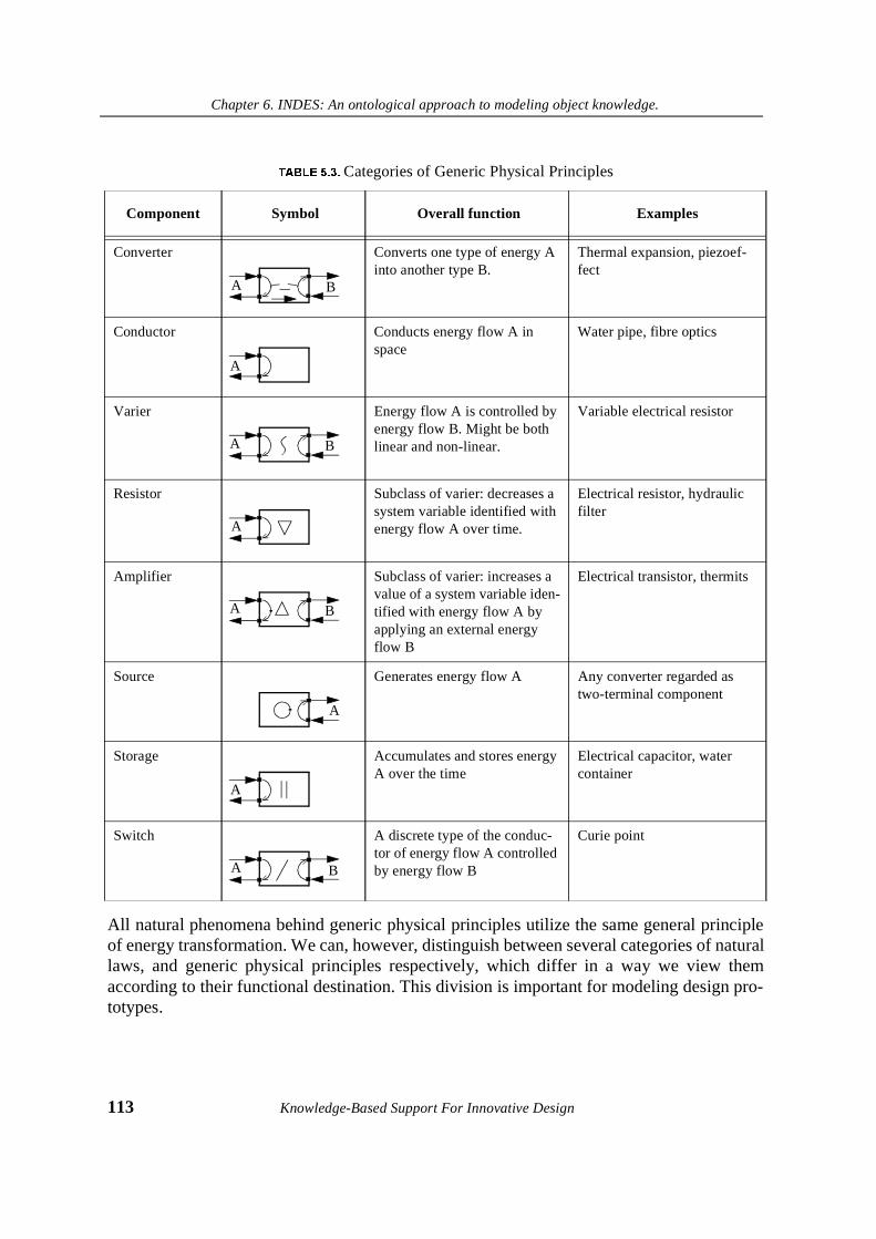
Chapter 6. INDES: An ontological approach to modeling object knowledge.
113 Knowledge-Based Support For Innovative Design
All natural phenomena behind generic physical principles utilize the same general principleof energy transformation. We can, however, distinguish between several categories of naturallaws, and generic physical principles respectively, which differ in a way we view themaccording to their functional destination. This division is important for modeling design pro-totypes.
7$%/(������Categories of Generic Physical Principles
Component Symbol Overall function Examples
Converter Converts one type of energy A into another type B.
Thermal expansion, piezoef-fect
Conductor Conducts energy flow A in space
Water pipe, fibre optics
Varier Energy flow A is controlled byenergy flow B. Might be both linear and non-linear.
Variable electrical resistor
Resistor Subclass of varier: decreases a system variable identified with energy flow A over time.
Electrical resistor, hydraulic filter
Amplifier Subclass of varier: increases a value of a system variable iden-tified with energy flow A by applying an external energy flow B
Electrical transistor, thermits
Source Generates energy flow A Any converter regarded as two-terminal component
Storage Accumulates and stores energy A over the time
Electrical capacitor, water container
Switch A discrete type of the conduc-tor of energy flow A controlled by energy flow B
Curie point
A B
A
A B
A
A B
A
A
A B
Chapter 6. INDES: An ontological approach to modeling object knowledge.
Knowledge-Based Support For Innovative Design 114
A number of component categories is distinguished in System Theory (such as resistors,inductors, capacitors) as well as in Bond Graphs (such as changer, varier, connector, chan-neler, store and source). INDES classification of GPP (Table 6.3) introduces eight categoriesof components based on the analysis of TRIZ collections of physical effects and physicalfunctions.
6.4.3 Generic Design Concept
A uniform way of modeling different GPPs and the law of energy conservation used to checkagainst boundary conditions make it possible to connect several GPPs into a more complexstructure that is labelled the Generic Design Concept (GDC). A GDC is a conceptualdescription of a new design consisting of the network of a GPP. The amount of GPPs that canbe networked into a GDC is unlimited.
Two GPP are allowed to be connected when:
1. The output energy flow of the first GPP and the input energy flow are of the sametype.
2. The values of the parameters of both flows are within the same generic intervals;
3. The boundary conditions are provided:
3.1.For explicit variables: E2in = -E1out
3.2.For implicit variables: ∆A1 = ∆A2
Example of a GDC consisting of one energy source and two converters is shown in Figure6.3.
Figure 6.3: Graphical form of generic design concept
We must however note, that there is no clear distinction between a GPP and a GDC. Thesame physical phenomenon can be represented as a GPP whereas under another level of
E1out
E1in
E0in
E0out
∆A0 ∆A1
E3out
E3in
E2in
E2out
∆A2 ∆A3
Energy source Converter 1 Converter 2
Chapter 6. INDES: An ontological approach to modeling object knowledge.
115 Knowledge-Based Support For Innovative Design
abstraction the same effect can be regarded as a combination of more primitive effects andthus represented by a set of connected GPPs. We therefore have decided to limit ourselves tomodeling those physical effects and phenomena which are available in physical encyclopae-dia and can be represented as system-theoretical models.
The concept of a GDC in INDES is similar to the concept of a compound prototype inYMIR. The difference is in the way a GDC and compound prototypes are obtained: whileYMIR proposes to model existing designs in terms of compound prototypes, INDES pro-poses to synthesise new GDCs each time when the new design specifications are available.Another difference is that GDC may consist of physical principles which belong to differentdomains, in contrast to YMIR.
6.5. Examples of modeled Physical Principles
In this section, we present the examples of modeled generic physical principles. Each physi-cal phenomenon is modeled as a GPP at the appropriate level of abstraction. The choice ofthe level of abstraction depends on what energy and form-related information on a physicaleffect is crucial to translate between physical and engineering levels and to check the appli-cability of translated knowledge against functional requirements. To illustrate our approachto modeling physical effects in details, we will analyse the effects of Joule heat and ThermalExpansion.
6.5.1 Joule Heat
Joule heat arises in a conductive material when an electrical current passes through the mate-rial. The heat is generated as a consequence of increasing internal energy of the material dueto collisions of migrating electrons which lose their energy. This effect is used in many tech-nical systems, like electric stoves, toasters and hair dryers.
According to INDES, the behaviour of a generic system model is expressed as a set of rela-tions between input and output system variables, where form-related variables serve as relat-ing parameters. The physical behaviour of the effect of Joule heat can be defined by theordered tuple:
where Uin and Iin are input voltage and current, Tout , Hout are the output temperature differ-ence and the heat flow.
R Uin I in,⟨ ⟩ Tout Hout,⟨ ⟩,⟨ ⟩=
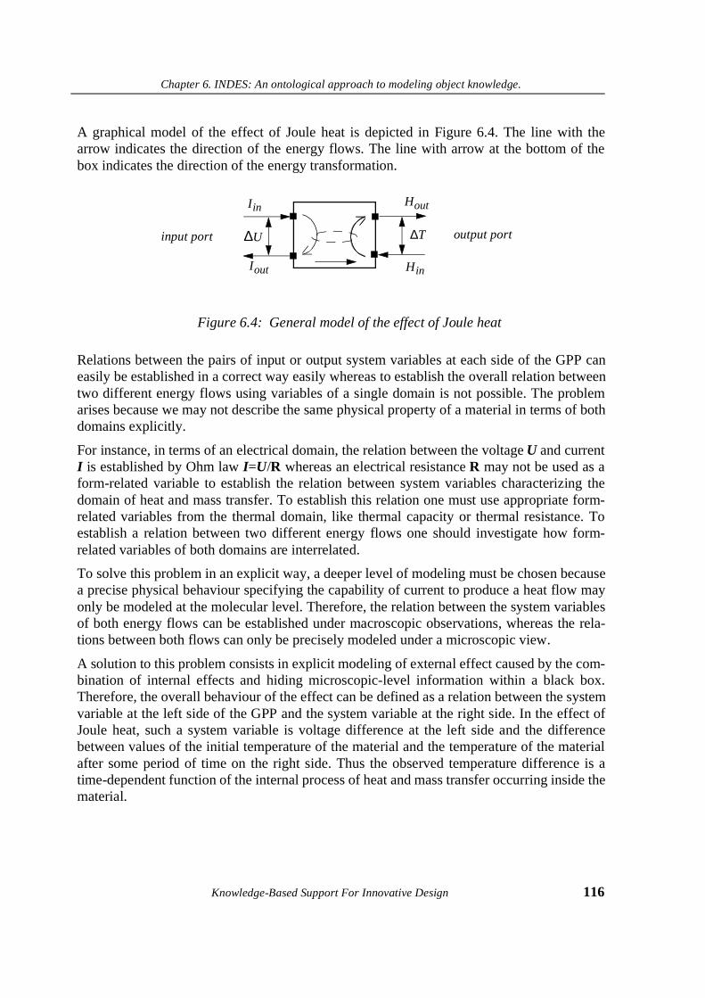
Chapter 6. INDES: An ontological approach to modeling object knowledge.
Knowledge-Based Support For Innovative Design 116
A graphical model of the effect of Joule heat is depicted in Figure 6.4. The line with thearrow indicates the direction of the energy flows. The line with arrow at the bottom of thebox indicates the direction of the energy transformation.
Figure 6.4: General model of the effect of Joule heat
Relations between the pairs of input or output system variables at each side of the GPP caneasily be established in a correct way easily whereas to establish the overall relation betweentwo different energy flows using variables of a single domain is not possible. The problemarises because we may not describe the same physical property of a material in terms of bothdomains explicitly.
For instance, in terms of an electrical domain, the relation between the voltage U and currentI is established by Ohm law I=U/R whereas an electrical resistance R may not be used as aform-related variable to establish the relation between system variables characterizing thedomain of heat and mass transfer. To establish this relation one must use appropriate form-related variables from the thermal domain, like thermal capacity or thermal resistance. Toestablish a relation between two different energy flows one should investigate how form-related variables of both domains are interrelated.
To solve this problem in an explicit way, a deeper level of modeling must be chosen becausea precise physical behaviour specifying the capability of current to produce a heat flow mayonly be modeled at the molecular level. Therefore, the relation between the system variablesof both energy flows can be established under macroscopic observations, whereas the rela-tions between both flows can only be precisely modeled under a microscopic view.
A solution to this problem consists in explicit modeling of external effect caused by the com-bination of internal effects and hiding microscopic-level information within a black box.Therefore, the overall behaviour of the effect can be defined as a relation between the systemvariable at the left side of the GPP and the system variable at the right side. In the effect ofJoule heat, such a system variable is voltage difference at the left side and the differencebetween values of the initial temperature of the material and the temperature of the materialafter some period of time on the right side. Thus the observed temperature difference is atime-dependent function of the internal process of heat and mass transfer occurring inside thematerial.
Hout
input port output port
Hin
I in
Iout
∆U ∆T
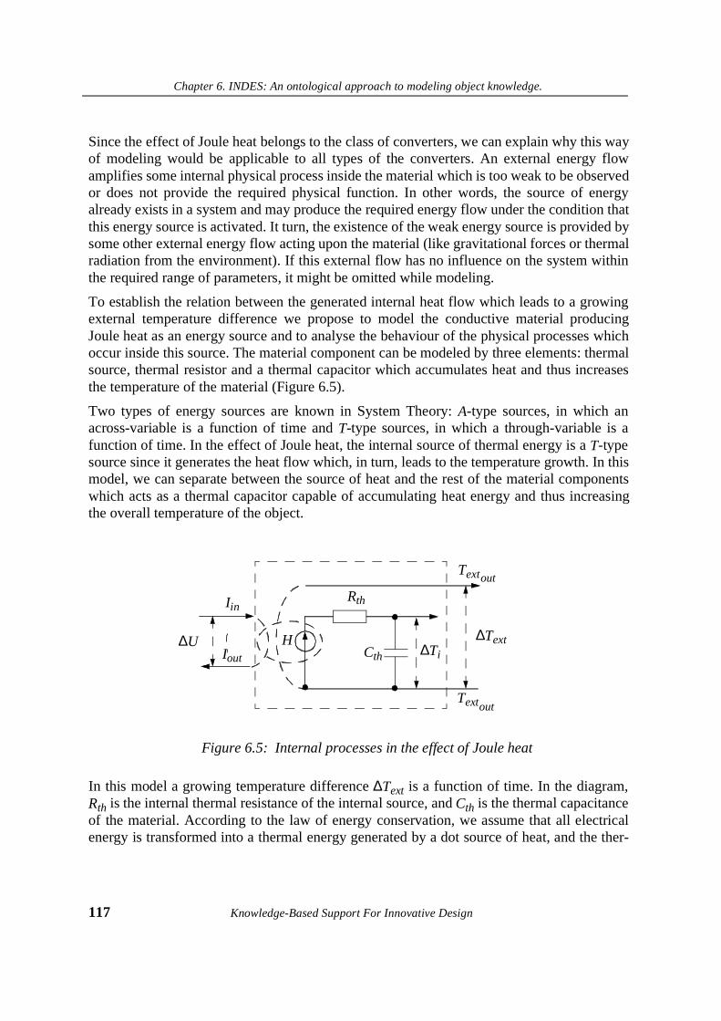
Chapter 6. INDES: An ontological approach to modeling object knowledge.
117 Knowledge-Based Support For Innovative Design
Since the effect of Joule heat belongs to the class of converters, we can explain why this wayof modeling would be applicable to all types of the converters. An external energy flowamplifies some internal physical process inside the material which is too weak to be observedor does not provide the required physical function. In other words, the source of energyalready exists in a system and may produce the required energy flow under the condition thatthis energy source is activated. It turn, the existence of the weak energy source is provided bysome other external energy flow acting upon the material (like gravitational forces or thermalradiation from the environment). If this external flow has no influence on the system withinthe required range of parameters, it might be omitted while modeling.
To establish the relation between the generated internal heat flow which leads to a growingexternal temperature difference we propose to model the conductive material producingJoule heat as an energy source and to analyse the behaviour of the physical processes whichoccur inside this source. The material component can be modeled by three elements: thermalsource, thermal resistor and a thermal capacitor which accumulates heat and thus increasesthe temperature of the material (Figure 6.5).
Two types of energy sources are known in System Theory: A-type sources, in which anacross-variable is a function of time and T-type sources, in which a through-variable is afunction of time. In the effect of Joule heat, the internal source of thermal energy is a T-typesource since it generates the heat flow which, in turn, leads to the temperature growth. In thismodel, we can separate between the source of heat and the rest of the material componentswhich acts as a thermal capacitor capable of accumulating heat energy and thus increasingthe overall temperature of the object.
Figure 6.5: Internal processes in the effect of Joule heat
In this model a growing temperature difference ∆Text is a function of time. In the diagram,Rth is the internal thermal resistance of the internal source, and Cth is the thermal capacitanceof the material. According to the law of energy conservation, we assume that all electricalenergy is transformed into a thermal energy generated by a dot source of heat, and the ther-
Iin
Iout
Rth
HCth ∆Ti
Text
Text
∆Text
out
out
∆U
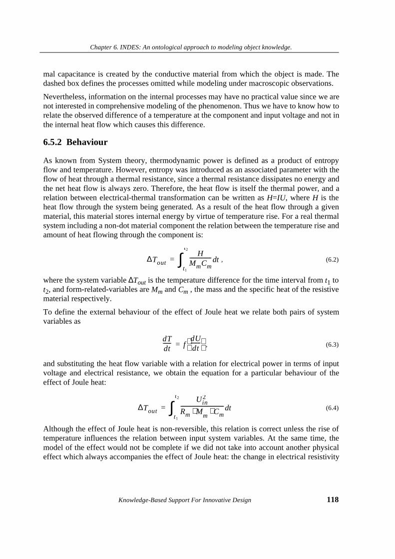
Chapter 6. INDES: An ontological approach to modeling object knowledge.
Knowledge-Based Support For Innovative Design 118
mal capacitance is created by the conductive material from which the object is made. Thedashed box defines the processes omitted while modeling under macroscopic observations.
Nevertheless, information on the internal processes may have no practical value since we arenot interested in comprehensive modeling of the phenomenon. Thus we have to know how torelate the observed difference of a temperature at the component and input voltage and not inthe internal heat flow which causes this difference.
6.5.2 Behaviour
As known from System theory, thermodynamic power is defined as a product of entropyflow and temperature. However, entropy was introduced as an associated parameter with theflow of heat through a thermal resistance, since a thermal resistance dissipates no energy andthe net heat flow is always zero. Therefore, the heat flow is itself the thermal power, and arelation between electrical-thermal transformation can be written as H=IU, where H is theheat flow through the system being generated. As a result of the heat flow through a givenmaterial, this material stores internal energy by virtue of temperature rise. For a real thermalsystem including a non-dot material component the relation between the temperature rise andamount of heat flowing through the component is:
, (6.2)
where the system variable ∆Tout is the temperature difference for the time interval from t1 tot2, and form-related-variables are Mm and Cm , the mass and the specific heat of the resistivematerial respectively.
To define the external behaviour of the effect of Joule heat we relate both pairs of systemvariables as
, (6.3)
and substituting the heat flow variable with a relation for electrical power in terms of inputvoltage and electrical resistance, we obtain the equation for a particular behaviour of theeffect of Joule heat:
(6.4)
Although the effect of Joule heat is non-reversible, this relation is correct unless the rise oftemperature influences the relation between input system variables. At the same time, themodel of the effect would not be complete if we did not take into account another physicaleffect which always accompanies the effect of Joule heat: the change in electrical resistivity
∆ToutH
MmCm---------------- td
t1
t2
∫=
dTdt------ f
dUdt-------
=
∆Tout
Uin2
Rm M⋅m
Cm⋅-------------------------------- td
t1
t2
∫=
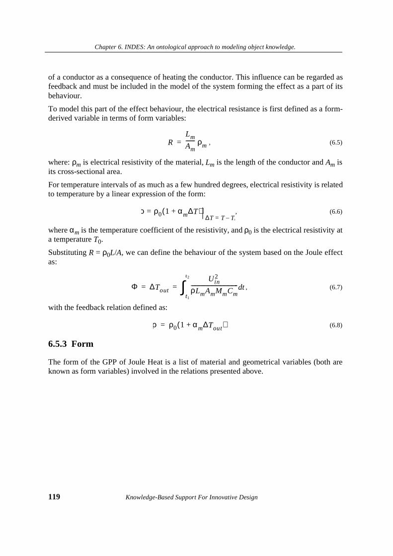
Chapter 6. INDES: An ontological approach to modeling object knowledge.
119 Knowledge-Based Support For Innovative Design
of a conductor as a consequence of heating the conductor. This influence can be regarded asfeedback and must be included in the model of the system forming the effect as a part of itsbehaviour.
To model this part of the effect behaviour, the electrical resistance is first defined as a form-derived variable in terms of form variables:
, (6.5)
where: ρm is electrical resistivity of the material, Lm is the length of the conductor and Am isits cross-sectional area.
For temperature intervals of as much as a few hundred degrees, electrical resistivity is relatedto temperature by a linear expression of the form:
, (6.6)
where αm is the temperature coefficient of the resistivity, and ρ0 is the electrical resistivity ata temperature T0.
Substituting R = ρ0L/A, we can define the behaviour of the system based on the Joule effectas:
, (6.7)
with the feedback relation defined as:
(6.8)
6.5.3 Form
The form of the GPP of Joule Heat is a list of material and geometrical variables (both areknown as form variables) involved in the relations presented above.
RLm
Am------- ρm=
ρ ρ0 1 αm∆T+( )=∆T T T0–=
Φ ∆Tout
Uin2
ρLmAmMmCm----------------------------------- td
t1
t2
∫= =
ρ ρ0 1 αm∆Tout+( )=

Chapter 6. INDES: An ontological approach to modeling object knowledge.
Knowledge-Based Support For Innovative Design 120
6.5.4 Overall model
In summary, an overall model of the effect of Joule heat includes three parts: form, structurespecified by input and output ports, and behaviour as a set of relations between system varia-bles. The overall model of the effect of Joule heat is presented in Tables 6.4, 6.5. and 6.6.
7$%/(������Behaviour of GPP of Joule heat
Type of relation Function Mathematical expression
Input system variables
Output system variables
Conversion relation
Feedback relation
7$%/(������Form of GPP based on Joule heat
Form parameter Form variable
Mass of an object Mm
Specific heat of material Cm
Electric resistivity of material ρ
Initial resistivity of material ρ0
Length of the object L
Cross-sectional area of the object Am
Temperature coefficient of resistivity αm
7$%/(������Structure of GPP based on Joule heat
Input Ports Output Ports
Iin , Uin Hout , Tout
Φin I in Uin,⟨ ⟩=I
AmU
ρmLm-------------=
Φout Hout Tout,⟨ ⟩=∆Tout
HMmCm
--------------- tdt1
t2
∫=
Φt r Tout Hout Uin I in, , ,⟨ ⟩=∆Tout
Uin2
ρLmAmMmCm
--------------------------------- tdt1
t2
∫=
Φf I in Tout,⟨ ⟩= I in U ρ⁄ 0 1 αm∆Tout+( )=
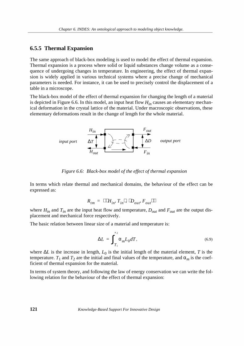
Chapter 6. INDES: An ontological approach to modeling object knowledge.
121 Knowledge-Based Support For Innovative Design
6.5.5 Thermal Expansion
The same approach of black-box modeling is used to model the effect of thermal expansion.Thermal expansion is a process where solid or liquid substances change volume as a conse-quence of undergoing changes in temperature. In engineering, the effect of thermal expan-sion is widely applied in various technical systems where a precise change of mechanicalparameters is needed. For instance, it can be used to precisely control the displacement of atable in a microscope.
The black-box model of the effect of thermal expansion for changing the length of a materialis depicted in Figure 6.6. In this model, an input heat flow Hin causes an elementary mechan-ical deformation in the crystal lattice of the material. Under macroscopic observations, theseelementary deformations result in the change of length for the whole material.
Figure 6.6: Black-box model of the effect of thermal expansion
In terms which relate thermal and mechanical domains, the behaviour of the effect can beexpressed as:
where Hin and Tin are the input heat flow and temperature, Dout and Fout are the output dis-placement and mechanical force respectively.
The basic relation between linear size of a material and temperature is:
, (6.9)
where ∆L is the increase in length, L0 is the initial length of the material element, T is thetemperature. T1 and T2 are the initial and final values of the temperature, and αm is the coef-ficient of thermal expansion for the material.
In terms of system theory, and following the law of energy conservation we can write the fol-lowing relation for the behaviour of the effect of thermal expansion:
Fout
input port output port
Fin
Hin
Hout
∆T ∆D
Rtm Hin Tin,⟨ ⟩ Dout Fout,⟨ ⟩,⟨ ⟩=
∆L αmL0 TdT1
T2
∫=

Chapter 6. INDES: An ontological approach to modeling object knowledge.
Knowledge-Based Support For Innovative Design 122
, (6.10)
or in exact form:
, (6.11)
where ∆D is the linear displacement of the element subjected to heating.
The overall model of the GPP presenting the effect of thermal expansion can be presentedanalogously to the GPP of Joule heat (section 6.6.4).
6.5.6 Example of Generic Design Concept
A generic design concept is synthesized on the basis of a causal chaining of several GPPsinto a physical system whose overall behaviour achieves the function required on the basis ofthe energy resources given. Two GPPs may be connected if two conditions are satisfied:
The GDC includes at least two components: an energy source and a GPP that provides therequired transformation of an energy or material parameter.
A topology for a Generic Design Concept can be synthesized which would be capable of per-forming the function “to control displacement” on the basis of the two effects describedabove: Joule heat and thermal expansion (Figure 6.7). The overall behaviour of the GDC isdefined by the following relation:
A mathematical expression comprising the overall GDC behaviour can be obtained by sub-stituting the input variables in an equation (5.10) with equation for the output variables (5.6):
(6.12)
The form of the GDC includes form-related variables which belong to both GPP.
To control the change of the resulting mechanical displacement, a variable resistor can beintroduced into the network. Therefore, an electrical resistance is a subfunction of mechani-cal displacement that controls, for instance, the length of the resistive material: Rm = f(Dext).The energy flow Dext is provided by an additional source of mechanical energy (figure 6.8).
dDdT------- f
dTdt------ F,
=
∆D αmL0 TdT1
T2
∫=
R Uin I in,⟨ ⟩ Fout Dout,⟨ ⟩,⟨ ⟩=
∆D αmL0
Uin2
Rm M⋅m
Cm⋅-------------------------------- td
t1
t2
∫=

Chapter 6. INDES: An ontological approach to modeling object knowledge.
123 Knowledge-Based Support For Innovative Design
Figure 6.7: GDC of a system performing a mechanical displacement as a function of changing the voltage difference
Figure 6.8: GDC of a system performing a mechanical displacement as a function of the change of the voltage difference via a variable electrical resistor (varier)
Hout
Hin
I in
Iout
∆U ∆T
Fout
Fin
∆D
Source of Joule heat Thermal expansionelectrical energy
Hout
Hin
Iin
Iout
∆U ∆T
Fout
Fin
∆D
Source of
Joule heat Thermal expansion
Iout
I in
∆U0
Varier
∆U
electrical energy Source of mechanical energy
∆Dext
Chapter 6. INDES: An ontological approach to modeling object knowledge.
Knowledge-Based Support For Innovative Design 124
6.6. Summary and Discussion
We discussed the framework for modeling sharable physical knowledge in uniform way. Toachieve uniformity in modeling we proposed to use an ontological approach for modelingdomain knowledge. The INDES ontology contains two sets of concepts: concepts for mode-ling physical components and concepts for modeling relations between the physical compo-nents.
The introduction of a concept of a Generic Physical Principle as a basic building block forconceptual engineering design makes it possible to develop a domain-independent, sharablecollection of physical phenomena. The reuse of the phenomena might be organized accord-ing to the multitude of physical functions each GPP is capable of performing.
In some sense, INDES can be viewed as extension of YMIR since it uses the same basicmodeling approach. However, there are three additional aspects which are unique features ofINDES:
1. YMIR regards specific design solutions as a source for generalization and modelingwhereas INDES uses collections of physical effects known in natural sciences.
2. The degree of conceptualization in INDES is higher than in YMIR: physical effectsare more generic in nature than models of specific designs.
3. INDES allows for cross-domain modeling whereas YMIR is limited to modelingonly domain knowledge.
Among the principal features of INDES are:
1. The basic knowledge structure is introduced for modeling sharable physical knowl-edge -- Generic Physical Principle. It incorporates both energy and material aspectsof physical principles that are needed to make instantiations of physical knowledgeinto design concepts.
2. The concept of a generic physical principle makes it possible to relate both materialand energy parameters of generic physical systems.
3. An ontological approach for modeling design knowledge is applied to model differ-ent types of physical principles in a uniform way and to evaluate future designsagainst physical realisability at the earliest stages.
4. To organize and structure a knowledge base of GPPs the available TRIZ collectionsof physical effects and phenomena can be used.
5. A uniform way of modeling and representing GPPs makes it possible to combineGPPs into more complex sharable structures labelled Generic Design Concepts.
In the rest of the book we will discuss how the INDES ontological concepts might be incor-porated into appropriate models of innovative design.
Chapter 7. Design Conflict
125 Knowledge-Based Support For Innovative Design
Chapter 7. Design Conflict
7.1. Introduction
In the previous chapter, we presented a basic concept for modelling object knowledge forconceptual engineering design - Generic Physical Principle (GPP). A GPP deals with a col-lection of tuples and assumes that specific values of variables involved in the GPP behaviourare supported but not identified with precise intervals. Such genericity ensures that the GPPcan be instantiated into a multitude of different design product descriptions. Our assumptionbehind the proposed framework is that we are able to model any design product and itsbehavoiur in terms of its generic physical principles.
The INDES-based innovative design is possible when a repository of GPPs is available. Theoveral conceptual design process consists of two steps: first, matching a function required todeliver with a function which is part of GPP(s) behaviour and second, synthesising a newdesign concept by networking the relevant GPPs.
This design procedure addresses the synthesis of a new design product based on the utiliza-tion of a new physical principle. However, this type of design does not support anotherimportant design activity: the problem of improving existing products. This type of designproblems occurs more frequently in engineering than designing completely new products.Due to this we may not neglect the type of engineering design which we labelled “innovativeredesign” (see Chapter 5). By innovative redesign we mean a design process which results insolutions that can be regarded as innovative modifications of existing products and whichmay not be obtained by routine redesign.
To organize a reasoning process about problems of innovative redesign, we introduce anumber of INDES strategic knowledge concepts. These are used for modelling innovativeredesign problems as well as providing rules for knowledge-based innovative redesign.
Chapter 7. Design Conflict
Knowledge-Based Support For Innovative Design 126
This chapter presents a key concept of innovative redesign - design conflict. This concept issimilar to Altshuller’s concept of the contradiction discussed in Chapter 3 and is used to for-mulate and model innovative redesign problems. However, the INDES notion of the designconflict is claimed to be more accurate than Altshuller’s notion of contradiction. We havetherefore decided to use another term to avoid confusion with the original TRIZ concept ofcontradiction.
In this chapter, we discuss how the design conflict can be used in modelling innovativedesign. First, we explain the role of contradiction in decomposing innovative design prob-lems. Second, we present a new concept for modelling a design product: a Design PrototypeModel. Next, we show how design conflict can be defined in terms of behaviour of theDesign Prototype Model. Finally, we give a formal definition of a design conflict and showhow the design conflict can be represented in terms of formal language.
7.2. Role of conflicts in problem decomposition
In general, the engineering design can be regarded as a process consisting of two phases:analysis and synthesis. Analysis involves obtaining and structuring information on a prob-lem, as well as dissecting it and investigating the characteristics of individual elements andthe interrelations between them. Analysis requires recognition, definition, structuring andordering. Synthesis involves the processing information obtained by forming links and con-necting elements to produce totally new effects, bringing them together in an orderly sum-mary. During the synthesis phase, the problem solving process gradually moves from aqualitative concept to a formal quantitative model. Synthesis can be regarded as a process ofsearching and finding plus composition and combination.
If the problem is complex and extensive, it can be decomposed into a set of manageable sub-problems. The decomposition process is not difficult to perform if the semantics of the prob-lem are clearly stated and both the space of involved variables and the solution space arewell-defined. In this case, the decomposition process can easily be described in formal lan-guage. However, the decomposition is only possible when a criterium, according to whichthe decomposition is performed is known.
In the case of innovative problems, the situation appears to be more difficult. So far, no for-mal representation of a decompostion procedure for innovative problems was possible due toa lack of such criteria and an ill-defined solution space. To solve this problem, the TRIZ con-cept of a contradiction is a means to decompose innovative design problems. To define whatthe space of possible solutions is, we will assume that innovative solutions are combinationsof generic physical principles obtained on the basis of an existing set of generic physicalprinciples.
As known from TRIZ, the same problem can be translated into a multitude of different con-tradictions. A choice of a contradiction to resolve is however made intuitively. For this rea-

Chapter 7. Design Conflict
127 Knowledge-Based Support For Innovative Design
son, many iterations are required to choose the “right” contradiction and come up with afeasible solution. In conclusion, we argue that a contradiction should only be constructed onthe basis of analysis of model of a design product but not the product itself.
7.3. Design Product Model
To check against possible design conflicts that will interfere with the desired improvement ofa design product, the latter should be formally modelled. We propose to perform such model-ling at a conceptual level in terms of Generic Physical Principles. The use of abstraction inmodelling is useful for two reasons: first, it enables focusing on certain aspects of a problem,second, it limits the number of variables involved thus simplifying the process of mathemati-cal modelling. Abstraction has long been recognized as a powerful AI technique for generalproblem solving as well as for solving non-trivial design problems using reasoning by anal-ogy (Bhatta & Goel [1994], Wolverton & Hayes-Roth [1995]).
To model existing design products in a uniform way recognizable by computer we introducea new INDES concept labelled a Design Product Model (DPM). Like a Generic Design Con-cept (GDC, Chapter 6), the Design Product Model is a network of GPPs. There is no differ-ence in modelling both the Generic Design Concept and the Design Prototype Model apartfrom identifying the generic values and intervals of variables in the GDC and specific valuesand intervals in the DPM. The labelling also indicates a way in which a model is obtained:GDC represents a solution, and DPM represents a problem.
Definition 7.1.
Design Product Model is a conceptual model of a design product presented as anetwork of Generic Physical Principles which constitute the existing designproduct or its part.
As a conceptual model of a real design product, the DPM preserves semantics of some partof a system which constitutes the product. Due to a black-box approach, detailed aspects ofsystem dynamics are neglected.
Assuming that it is possible to build a knowledge base of GPPs which stores all known phys-ical effects and phenomena, a new DPM can be composed of predefined building blocks bymapping between functions defined for the design product components and the availablegeneric physical principles stored in the knowledge base. The advantage of translating a realdesign product onto a network of predefined generic physical principles is that the resultingDPM will incorporate consistent and correct information about the generic behaviour of eachGPP the DPM consists of.

Chapter 7. Design Conflict
Knowledge-Based Support For Innovative Design 128
7.4. Theory of Design Conflict
One of the basic INDES assumptions is that a new requirement, no matter in what form it isformulated, can always be expressed in terms of a system’s behaviour particularly in terms offunctional specifications. The task of translation between various forms of requirement spec-ifications is outside the scope of the book but we refer to the TRIZ-based Functional Analy-sis technique (Litvin & Guerassimov [1991]). This technique was tested on a large number ofinventive problems and has proven succesfull for the exact identification of the functionalcontext of a system’s components.
Regarding innovative design as the task of mapping between functions and physical princi-ples, two types of problems can be identified:
1. To change the value of an existing form or system variable (a particular case is toeliminate the variable, that is, to make its value equal to zero).
2. To Introduce a new variable with the certain value or the interval of the values.
In both cases, in order to meet the new requirement, a selected design product needs to beredesigned. A redesign process consists of performing a modification to the product’s struc-ture and behaviour so that the modified product will meet the requirements.
Our contribution to the definition of innovative redesign (first proposed in Goel [1989]) isthat innovative design can be distinguished from routine redesign according to the presenceof design conflict. We argue that it is possible to make a conclusion on which general prob-lem solving method should be chosen by verifying if a problem contains a conflict. Accord-ing to this, a procedure of routine redesign may be applied if no conflict is identified whileinnovative redesign is required when the problem involves a design conflict.
INDES regards design conflict as a concept which establishes a specific type of relationbetween two particular variables involved into the DPM’s behaviour. This relation defineswhat variables will have conflicting values if the new requirement is met by the routine rede-sign of the product. The design conflict can be specified when two behaviours are compared:
1. The DPM’s behaviour which corresponds the specifications but does not satisfy thedesigner.
2. A behaviour the DPM will possess after a routine redesign would have been per-formed to satisfy the designer’s demand.
These two DPM states can be evaluated by the correctness of the overall system’s behaviour.Two types of behaviour can be distinguished:
• Correct system behaviour: At any moment in time, the values of all system parame-ters belong to the overall space of specified parameters.
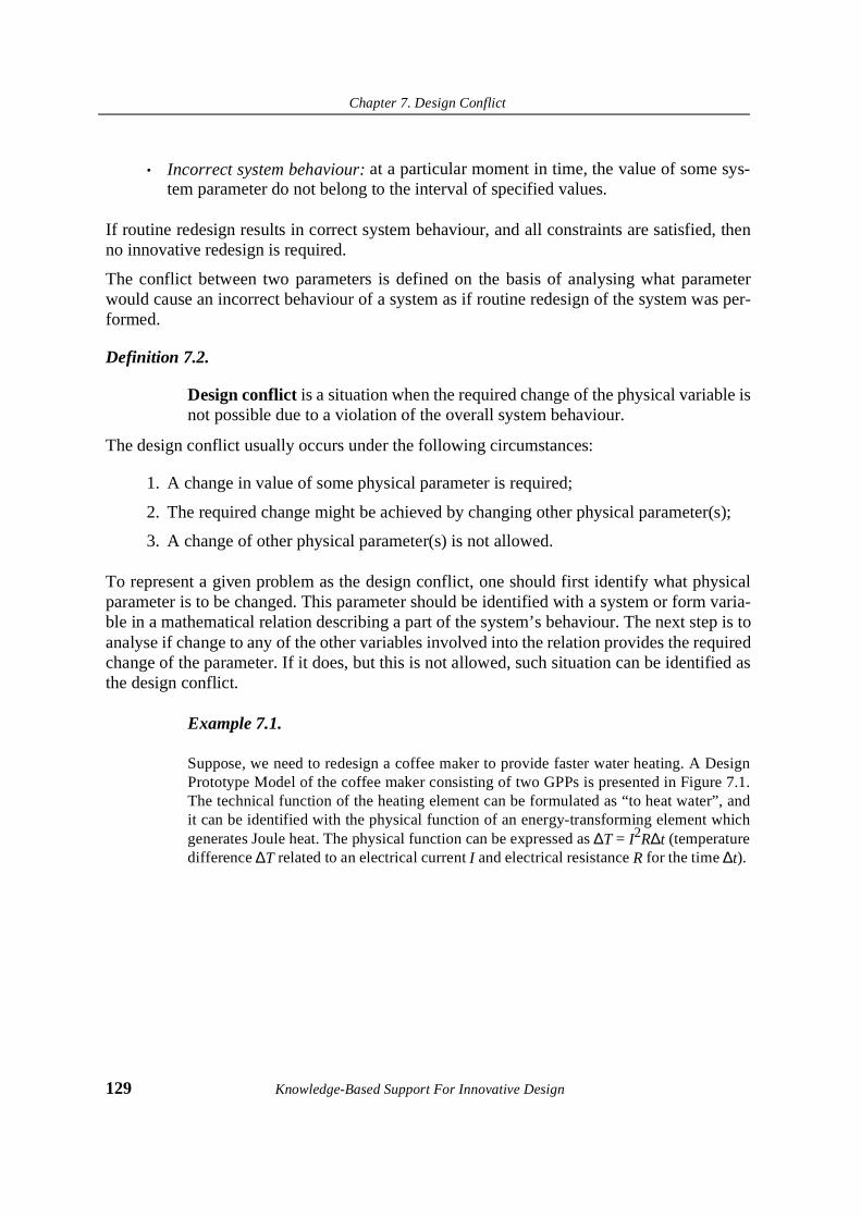
Chapter 7. Design Conflict
129 Knowledge-Based Support For Innovative Design
• Incorrect system behaviour: at a particular moment in time, the value of some sys-tem parameter do not belong to the interval of specified values.
If routine redesign results in correct system behaviour, and all constraints are satisfied, thenno innovative redesign is required.
The conflict between two parameters is defined on the basis of analysing what parameterwould cause an incorrect behaviour of a system as if routine redesign of the system was per-formed.
Definition 7.2.
Design conflict is a situation when the required change of the physical variable isnot possible due to a violation of the overall system behaviour.
The design conflict usually occurs under the following circumstances:
1. A change in value of some physical parameter is required;
2. The required change might be achieved by changing other physical parameter(s);
3. A change of other physical parameter(s) is not allowed.
To represent a given problem as the design conflict, one should first identify what physicalparameter is to be changed. This parameter should be identified with a system or form varia-ble in a mathematical relation describing a part of the system’s behaviour. The next step is toanalyse if change to any of the other variables involved into the relation provides the requiredchange of the parameter. If it does, but this is not allowed, such situation can be identified asthe design conflict.
Example 7.1.
Suppose, we need to redesign a coffee maker to provide faster water heating. A DesignPrototype Model of the coffee maker consisting of two GPPs is presented in Figure 7.1.The technical function of the heating element can be formulated as “to heat water”, andit can be identified with the physical function of an energy-transforming element whichgenerates Joule heat. The physical function can be expressed as ∆T = I2R∆t (temperaturedifference ∆T related to an electrical current I and electrical resistance R for the time ∆t).
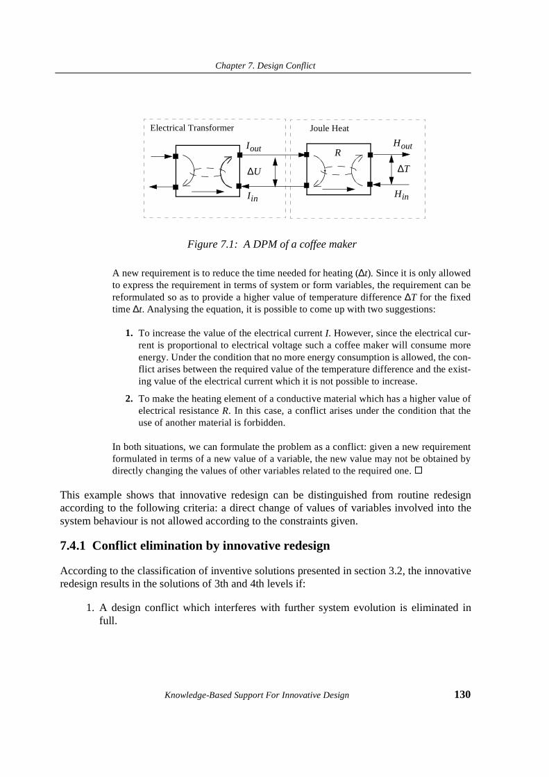
Chapter 7. Design Conflict
Knowledge-Based Support For Innovative Design 130
Figure 7.1: A DPM of a coffee maker
A new requirement is to reduce the time needed for heating (∆t). Since it is only allowedto express the requirement in terms of system or form variables, the requirement can bereformulated so as to provide a higher value of temperature difference ∆T for the fixedtime ∆t. Analysing the equation, it is possible to come up with two suggestions:
1. To increase the value of the electrical current I. However, since the electrical cur-rent is proportional to electrical voltage such a coffee maker will consume moreenergy. Under the condition that no more energy consumption is allowed, the con-flict arises between the required value of the temperature difference and the exist-ing value of the electrical current which it is not possible to increase.
2. To make the heating element of a conductive material which has a higher value ofelectrical resistance R. In this case, a conflict arises under the condition that theuse of another material is forbidden.
In both situations, we can formulate the problem as a conflict: given a new requirementformulated in terms of a new value of a variable, the new value may not be obtained bydirectly changing the values of other variables related to the required one. �
This example shows that innovative redesign can be distinguished from routine redesignaccording to the following criteria: a direct change of values of variables involved into thesystem behaviour is not allowed according to the constraints given.
7.4.1 Conflict elimination by innovative redesign
According to the classification of inventive solutions presented in section 3.2, the innovativeredesign results in the solutions of 3th and 4th levels if:
1. A design conflict which interferes with further system evolution is eliminated infull.
Iout
I in
∆U
Hout
Hin
∆T
Electrical Transformer Joule Heat
R
Chapter 7. Design Conflict
131 Knowledge-Based Support For Innovative Design
2. A solution resulting from the design conflict elimination utilizes a physical principlethat has never been used in the system before.
A comparative study of the TRIZ problem solving techniques led us to the conclusion that allof them can be subdivided into three general methods for eliminating conflicts applicable to aconflict-based model of innovative design problem as discussed in the previous chapter:
• Spatial elimination of conflicts. This method states that potentially conflictingparameters should be separated in space thus eliminating the relation between con-flicting parameters.
• Temporal elimination of conflicts. This method means that potentially conflictingactions should be performed within different time intervals.
• Elimination of conflicts by changing physical contents. To avoid the conflict, newphysical components are introduced into the system or certain components whichcause the conflict are replaced with those that do not cause the conflict.
All three methods can not be performed without a conceptual change to the physical contentsof a design prototype. As a conclusion, in order to build a computational model of innovativeredesign, we first need to formulate principles for changing the physical contents in terms ofpreviously introduced INDES concepts.
In the next chapter, we will formulate a general methodology for innovative redesign utiliz-ing a framework of model-based problem solving.
7.5. Implementation
To give an example of how a design conflict can be used in a practical way, we can definetwo rules of conflict analysis in terms of first-order logics.
First, we formally define notions of correct and incorrect system behaviour:
• Correct system behaviour: At any moment in time, the space A of actual values ofall system parameters belong to the overall space of permitted (in accordance withdesign specifications) parameters S, that is, A ⊆ S.
• Incorrect system behaviour: at a particular moment in time, the value PAi of some
system parameter Pi does not belong to the interval of specified values PSi that is,
PAi ⊄ PS
i.
If we express a space of interrelated parameters within a system as PI ( a subset of PS), andestablish a goal of problem solving as expanding a range of possible values for some param-eter Pi , then a formal representation of a relation defining the conflicting value is:
Chapter 7. Design Conflict
Knowledge-Based Support For Innovative Design 132
CONFLICT_VALUE(PAi, Pi, P
E , t) ←
PAi ∈ PE
and PE ⊄ S
and ∃Pj → PAj ∉ PE
and Pi , Pj ∈ PI ,
where PE is the required extension of existing space of values PS; Pj is the variable function-ally related to Pi .
We can define the relation CONFLICT between two variables Pi and Pj if there is a func-tional relation between them RELATED(Pi , Pj ) ← Pi , Pj ∈ PI:
CONFLICT(Pi , Pj , t) ←
RELATED(Pi , Pj )
and PAi ∈ PE
and PAj ∉ PE
and PAj ∈ S
and PE ⊄ S .
Although this relation only defines a conflict between two particular variables, similar rela-tions can be defined for Pi and any other variable of the set PI if the value of the latter causesincorrect behaviour of a system when changed.
A possible method for preventing a system from appearance of the conflict consists of find-ing any such parameter which belongs to PI so that it would be allowed to alter its valuewithout producing an undesired result. As a consequence, the value of Pi will also alter.However, when none of values of the related variables may be altered to provide the requiredvalue of Pi then a conceptual change of the existing physical structure of the system is neces-sary.
7.5.1 Benefits from the INDES definition of design conflict
Apart from a more precise definition of the design conflict, our approach solves one of themost difficult problems of TRIZ: what components to include in a problem model. As seen in
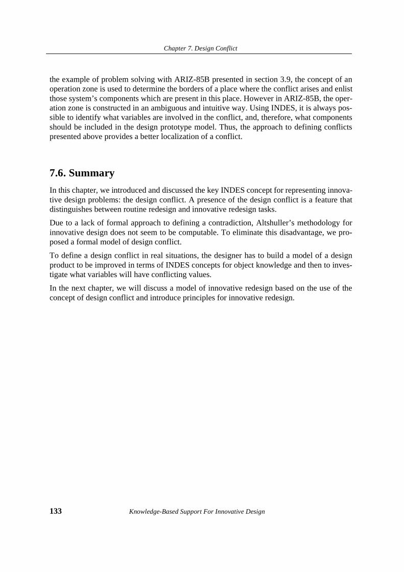
Chapter 7. Design Conflict
133 Knowledge-Based Support For Innovative Design
the example of problem solving with ARIZ-85B presented in section 3.9, the concept of anoperation zone is used to determine the borders of a place where the conflict arises and enlistthose system’s components which are present in this place. However in ARIZ-85B, the oper-ation zone is constructed in an ambiguous and intuitive way. Using INDES, it is always pos-sible to identify what variables are involved in the conflict, and, therefore, what componentsshould be included in the design prototype model. Thus, the approach to defining conflictspresented above provides a better localization of a conflict.
7.6. Summary
In this chapter, we introduced and discussed the key INDES concept for representing innova-tive design problems: the design conflict. A presence of the design conflict is a feature thatdistinguishes between routine redesign and innovative redesign tasks.
Due to a lack of formal approach to defining a contradiction, Altshuller’s methodology forinnovative design does not seem to be computable. To eliminate this disadvantage, we pro-posed a formal model of design conflict.
To define a design conflict in real situations, the designer has to build a model of a designproduct to be improved in terms of INDES concepts for object knowledge and then to inves-tigate what variables will have conflicting values.
In the next chapter, we will discuss a model of innovative redesign based on the use of theconcept of design conflict and introduce principles for innovative redesign.

Knowledge-Based Support For Innovative Design 134

Chapter 8. Innovative Redesign
135 Knowledge-Based Support For Innovative Design
Chapter 8. Innovative Redesign
"Problems cannot be solved by thinking within the framework withinwhich the problems were created"
Albert Einstein
8.1. Introduction
In the previous chapter, we introduced and discussed two INDES concepts for modelinginnovative design problems: a Design Prototype Model and a Design Conflict. We also haveshown in which way they can be used to formulate innovative design problems.
In this chapter, we present INDES-based model of knowledge-intensive innovative redesignwhich organizes the use of physical knowledge for solving those inventive problems thatcontain design conflicts.
First, we discuss why it is important to eliminate design conflicts from the point of view ofthe technology evolution. Second, we discuss the role of physical knowledge in this process.
Next, we introduce two axioms of innovative redesign which we will use to build a formalbasis for the modeling innovative redesign. A number of domain-independent innovativeredesign principles drawn from the axioms are also proposed. These principles are desig-nated to solve particular design problems that result in identical problem models.
Then, we present a structure of INDES-based innovative redesign.
In the end of the chapter, we show how INDES-based innovative redesign can be used inpractise by a case study.

Chapter 8. Innovative Redesign
Knowledge-Based Support For Innovative Design 136
8.2. Role of physical knowledge for design conflict elimination
The first artificial tools aimed at work simplification were stones controlled by the physicalforce of a man’s hand. A growth of demands and requirements has resulted in further compli-cation of the working tools: new purposes were thought of, disadvantages had to be removed.The physical force of a hand was replaced with a force of a horse, then water flow, steam,nuclear energy, and so forth. This resulted in the creation of what have been known today asdesign products: artificially created physical systems supposed to deliver specific functions.
In every situation, however, designers are looking for ways to improve the existing products.Studies of patent collections indicated that most inventions result from improvement ofalready known products delivering the same function. In most cases, such the improvementis often achieved by complicating the existing products.
If we define the degree of complexity of a design product as a relative factor involving ofcomponents and interactions between the objects constituting the product, then the trend of“complexity growth” can be observed in engineering. It states that attempts to achieve a bet-ter performance of any product and satisfy the growing number of design constraints leads tothe growth of the number of objects, and, as a consequence, interactions between the objects(Devoino [1993]).
In summary, every new invention provides improvement of performance and productivity,but at the expenses of growing complexity and costs. Such a phase of the technology evolu-tion is known as a phase of system complexity growth1. The better overall performance isrequired, the larger number of material-energy transformations in the product is observed.
However, evolution of any product without replacing a physical principle the product isbased upon will finally face a barrier put by the physical limits of the principle. To evolvefurther, the physical limits must be eliminated. This is only possible by replacing a physicalprinciple the product is based upon with a new physical principle which will fulfil the samefunction with a better performance.
Example 8.1.
Systems for sound recording have evolved along expanding the frequency range. Eachtime, a new physical principle was used to expand the range: 1) a mechanical principle(wax roll) 2) a magnetic principle (metal tape), 3) an optical principle (digital recording -audio CD or metal tape).
The next step of evolution known as the complexity reduction2 phase sets off when a newphysical principle is proposed to overcome a barrier established by the nature of previous
1. The phase of system complexity growth in INDES can be identified with the trend of an increase the number of sub-stance-field interactions in TRIZ (Chapter 3). However, as shown further in the text, we needed to change the label to make the whole picture of technology evolution more consistent.

Chapter 8. Innovative Redesign
137 Knowledge-Based Support For Innovative Design
physical principle. Such a conceptual change can be identified with resolving a fundamentaldesign conflict which is not possible to eliminate by available domain-specific methods.Some essential component of a system (for instance, a mechanical cutter) is replaced with anew component utilizing a different physical principle (for instance, a laser beam).
However, during the evolution, a new product tends to develop its subsystems and find moreand more applications. As a result, another phase of the complexity growth starts. Newdemands and requirements make the product develop the number of interactions again. (Fig-ure 8.1).
From the INDES point of view, this trend can be formulated in terms of material-energyinteractions. Therefore, evolution of any artificial system delivering a certain function passestwo phases:
• complexity growth: any system tends to increase a number of material-energyinteractions during its evolution;
• complexity reduction: a number of interacting components needed to fulfil a func-tion is replaced with a fewer number of interactions due to the utilization of a newphysical principle.
Such interpretation of the system evolution forms a theoretical foundation for our model ofinnovative redesign.
On the basis of our interpretation of technology evolution process, we can give more precisedefinition of innovative redesign:
Definition 8.1.
Innovative Redesign is a specific type of engineering design which involveselimination of design conflicts by a conceptual change to a physical structure ofan existing design product.
Respectively, two types of innovative redesign can be distinguished:
1. Innovative Redesign by complicating an existing system: a physical principlebehind its function is preserved whereas a number of material-energy interactionsgrows.
2. Innovative Redesign by utilizing a new physical principle behind the main function.
2. The trend of complexity reduction is similar to TRIZ trend of transition to microlevel, although such comparison is rather rough since TRIZ does not specify how to provide such transition in terms of interacting material objects and energy flows.
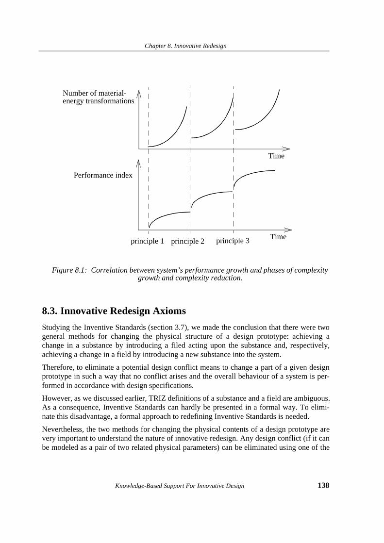
Chapter 8. Innovative Redesign
Knowledge-Based Support For Innovative Design 138
Figure 8.1: Correlation between system’s performance growth and phases of complexity growth and complexity reduction.
8.3. Innovative Redesign Axioms
Studying the Inventive Standards (section 3.7), we made the conclusion that there were twogeneral methods for changing the physical structure of a design prototype: achieving achange in a substance by introducing a filed acting upon the substance and, respectively,achieving a change in a field by introducing a new substance into the system.
Therefore, to eliminate a potential design conflict means to change a part of a given designprototype in such a way that no conflict arises and the overall behaviour of a system is per-formed in accordance with design specifications.
However, as we discussed earlier, TRIZ definitions of a substance and a field are ambiguous.As a consequence, Inventive Standards can hardly be presented in a formal way. To elimi-nate this disadvantage, a formal approach to redefining Inventive Standards is needed.
Nevertheless, the two methods for changing the physical contents of a design prototype arevery important to understand the nature of innovative redesign. Any design conflict (if it canbe modeled as a pair of two related physical parameters) can be eliminated using one of the
Number of material-
Performance index
Timeprinciple 1 principle 2
energy transformations
Time
principle 3

Chapter 8. Innovative Redesign
139 Knowledge-Based Support For Innovative Design
two methods. Therefore, we decided to incorporate both methods into our model of innova-tive redesign. Since we aim at building a formal framework of innovative redesign, we usedthese two general methods as a basis to formulate two axioms of innovative redesign:
1. Innovative Redesign Axiom 1. The value of a form variable representing somematerial parameter of a system can be altered by introducing a new energy flow intothe system that is capable of altering the value of the form variable.
2. Innovative Redesign Axiom 2. The value of a system variable identified with someenergy parameter of a system can be altered by introducing a new material objectinto the system that is capable of altering the value of the system variable.
As follows from the physical validity of these two axioms, innovative redesign is applicableto any design problem that involves material-energy transformations and can be formulatedas a design conflict.
8.4. Innovative Redesign Principles
In this section, we introduce the concept of Innovative Redesign Principle. We also distin-guish two particular methods for innovative redesign: Expansion Method and ReplacementMethod. Then, we present several specific Innovative Redesign Principles drawn from theInnovative Redesign Axioms.
8.4.1 Definition of the Innovative Redesign Principle
According to the two phases of “complexity growth-reduction” described above, we distin-guish between two particular methods of innovative redesign:
1. Expansion Method. To eliminate a design conflict is possible by expanding thespace of physical variable(s) used in a Design Prototype Model (DPM). A new vari-able(s) can be introduced into the DPM by adding new physical principles to theexisting ones the DPM is based upon. The newly introduced variables should pro-vide a necessary change in the required value of the variable and prevent the DPM’sbehaviour from being violated.
2. Replacement Method. To eliminate a design conflict, a physical principle which isresponsible for causing a design conflict can be replaced with another one physicalprinciple. In this situation, a space of system variables might remain the same, but apart of the space of form variables is replaced with another parameters.
Both methods are possible to use through the Innovative Redesign Principle (IRP) which isthe essential concept of the INDES ontology. An IRP belongs to the category of strategicknowledge since it defines how to process object knowledge.
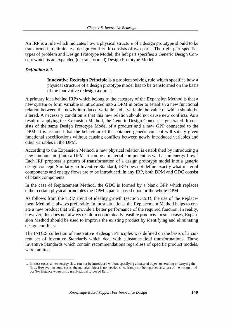
Chapter 8. Innovative Redesign
Knowledge-Based Support For Innovative Design 140
An IRP is a rule which indicates how a physical structure of a design prototype should to betransformed to eliminate a design conflict. It consists of two parts. The right part specifiestypes of problem and Design Prototype Model; the left part specifies a Generic Design Con-cept which is an expanded (or transformed) Design Prototype Model.
Definition 8.2.
Innovative Redesign Principle is a problem solving rule which specifies how aphysical structure of a design prototype model has to be transformed on the basisof the innovative redesign axioms.
A primary idea behind IRPs which belong to the category of the Expansion Method is that anew system or form variable is introduced into a DPM in order to establish a new functionalrelation between the newly introduced variable and a variable the value of which should bealtered. A necessary condition is that this new relation should not cause new conflicts. As aresult of applying the Expansion Method, the Generic Design Concept is generated. It con-sists of the same Design Prototype Model of a product and a new GPP connected to theDPM. It is assumed that the behaviour of the obtained generic concept will satisfy givenfunctional specifications without causing conflicts between newly introduced variables andother variables in the DPM.
According to the Expansion Method, a new physical relation is established by introducing anew component(s) into a DPM. It can be a material component as well as an energy flow.1
Each IRP proposes a pattern of transformation of a design prototype model into a genericdesign concept. Similarly an Inventive Standard, IRP does not define exactly what materialcomponents and energy flows are to be introduced. In any IRP, both DPM and GDC consistof blank components.
In the case of Replacement Method, the GDC is formed by a blank GPP which replaceseither certain physical principles the DPM’s part is based upon or the whole DPM.
As follows from the TRIZ trend of ideality growth (section 3.5.1), the use of the Replace-ment Method is always preferable. In most situations, the Replacement Method helps to cre-ate a new product that will provide a better performance of the required function. In reality,however, this does not always result in economically feasible products. In such cases, Expan-sion Method should be used to improve the existing product by identifying and eliminatingdesign conflicts.
The INDES collection of Innovative Redesign Principles was defined on the basis of a cur-rent set of Inventive Standards which deal with substance-field transformations. ThoseInventive Standards which contain recommendations regardless of specific product models,were omitted.
1. In most cases, a new energy flow can not be introduced without specifying a material object generating or carrying the flow. However, in some cases, the material object is not needed since it may not be regarded as a part of the design prod-uct (for instance when using gravitational forces of Earth).

Chapter 8. Innovative Redesign
141 Knowledge-Based Support For Innovative Design
The collection of IRP consists of rules structured respectively a type of a problem and designconstraints which define permission on introduction of additional energy flows and materialcomponents.
In general, an IRP is a problem solving method which defines what modification of a physi-cal structure of a design product modeled as a DPM should be made in terms of energy-mate-rial relations. Given a DPM and a description of a design conflict formulated with respect tothe DPM behaviour, the IRP defines two product models: a source Design Product Modelwhich contains the design conflict and a target GDC which does not contain the conflict.
In the next sections, we will give several examples of Innovative Redesign Principles basedon the Expansion Method written in form of production rules.
8.4.2 IRP applicable to non-conflicting situations
In certain situations, engineering design might be not concerned with conflict situations. Thishappens when a source DPM is incomplete and consists of a single material component or anenergy flow. Usually such problems address to the problems of new design synthesis. Forinstance, it might be a problem of processing a material when no design of a processingmachine is yet available as well as a problem of preventing something from heating. There-fore, no conflict might be identified in such situations due to missing data. Such the problemsappear to be difficult to solve due to a lack of knowledge of what physical principle to use todeliver the required function. In such situations, application of an IRP based on the direct useof Innovative Redesign Axioms should be considered first.
To build a target GDC for changing the value of form variable, IRP-1 can be used (Figure8.2):
IREP-1:
IF it is required to alter the value of the form variable M1and no conflict can be identified
THEN the energy flow Ex should be applied to the material component so that the required value of the form variable M1 is obtained.
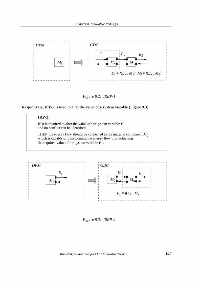
Chapter 8. Innovative Redesign
Knowledge-Based Support For Innovative Design 142
Figure 8.2: IREP-1
Respectively, IRP-2 is used to alter the value of a system variable (Figure 8.3).
Figure 8.3: IREP-2
IRP-2:
IF it is required to alter the value of the system variable E1and no conflict can be identified
THEN the energy flow should be connected to the material component M0 which is capable of transforming the energy flow thus achieving the required value of the system variable E1.
M1
E2 = f(Ex , M1); M1= f(Ex , M0);
ExE0
Mx
E2
M1
DPM GDC
Ex = f(E1 , Mx);
E1
M0
Ex
MxM0
E1
DPM GDC

Chapter 8. Innovative Redesign
143 Knowledge-Based Support For Innovative Design
8.4.3 IRP for conflict elimination
Another part of the IRP collection is applicable to those problems that can be modeled interms of a design conflict. A method for the design conflict elimination depends on whatconstraints are defined with respect to permitted modifications of a DPM. A diagram of aDPM that contains a design conflict CONFLICT(E1, E2) is shown in Fig. 8.4.
Figure 8.4: A DPM with conflict
The rule IRP-1-1 is applicable in situations when there is the need to alter the value of a sys-tem variable, but the values of neither form nor system variables related to it are not allowedto alter. Available constraints do not limit introduction of other components between the two(Figure 8.5).
IRP-1-1:
IF it is required to alter the value of the system variable E2 and this can not be done by changing neither M2 nor E1and there is a conflict relation CONFLICT(E1, E2),
THEN the material component Mx should be introduced to provide the required value of the system variable E1.
E2 = f(E1 , M2); CONFLICT(E1, E2)
E1E0
M1
E2
M2

Chapter 8. Innovative Redesign
Knowledge-Based Support For Innovative Design 144
Figure 8.5: IREP-1-1
A particular constraint might be applied to a problem: a specification of how the value of asystem variable should be altered. In the case of a decrease, a new resistive componentshould br introduced into a system (IRP-1-2, Figure 8.6). If an increase is required, a compo-nent which amplifies the current value of the system variable related to the needed one isintroduced (IRP-1-3, Figure 8.7). Both IRP should be used in situations when no limitationson introduction of new components between the two are specified.
IRP-1-2: (A particular case of IRP-1)
IF it is required to decrease the value of the system variable E2 and this can not be done by changing neither M2 nor E1 and there is the conflict relation CONFLICT(E1, E2),
THEN the material component Mx (resistor) should be introduced to provide the required decrease of the value of the system variable E1.
E2 = f(E1 , M2)
E1E0
M1
E2
M2
E2 = f(Ex , M2)
E1E0
M1
E2
M2
Ex
Mx
CONFLICT(E1, E2)
DPM GDC
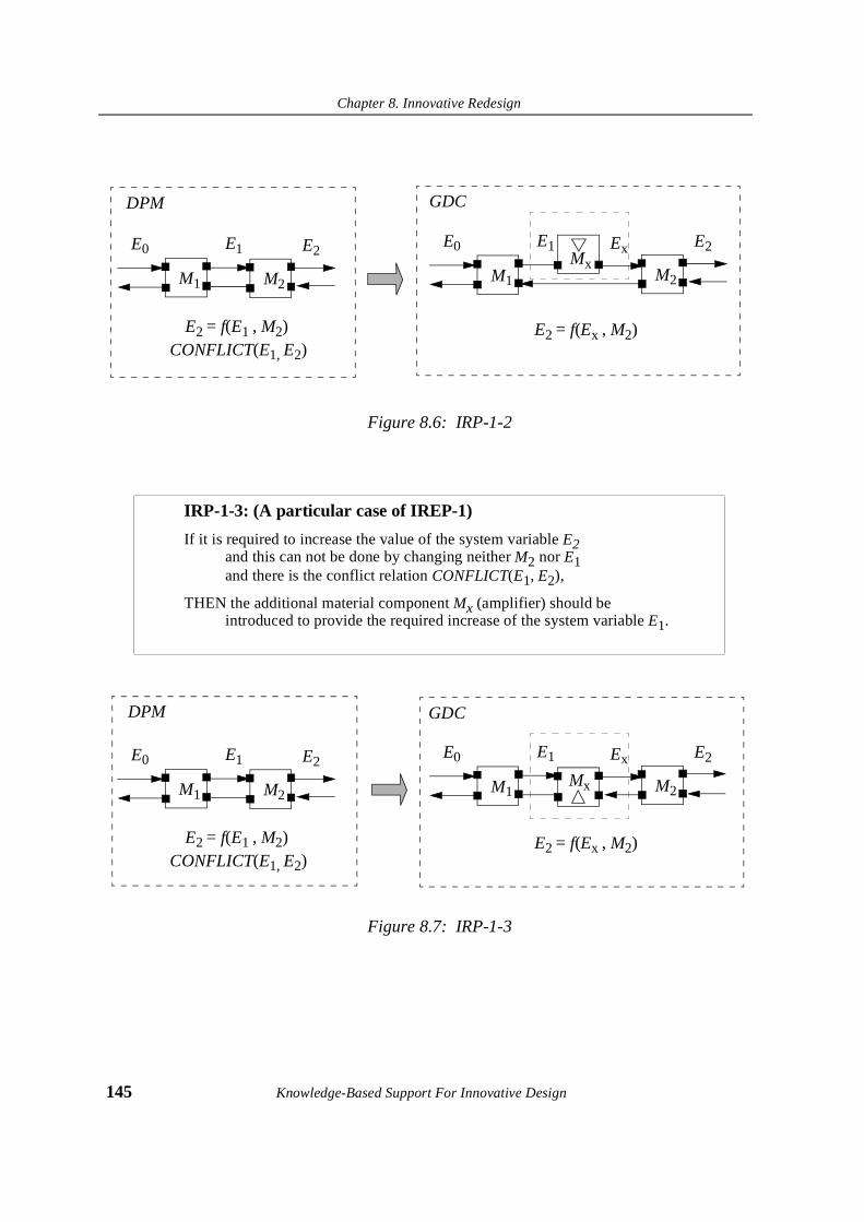
Chapter 8. Innovative Redesign
145 Knowledge-Based Support For Innovative Design
Figure 8.6: IRP-1-2
Figure 8.7: IRP-1-3
IRP-1-3: (A particular case of IREP-1)
If it is required to increase the value of the system variable E2 and this can not be done by changing neither M2 nor E1 and there is the conflict relation CONFLICT(E1, E2),
THEN the additional material component Mx (amplifier) should be introduced to provide the required increase of the system variable E1.
E2 = f(E1 , M2)
E1E0
M1
E2
M2
E2 = f(Ex , M2)
E1E0
M1
E2
M2
ExMx
CONFLICT(E1, E2)
DPM GDC
E2 = f(E1 , M2)
E1E0
M1
E2
M2
E2 = f(Ex , M2)
E1E0
M1
E2
M2
Ex
Mx
CONFLICT(E1, E2)
DPM GDC
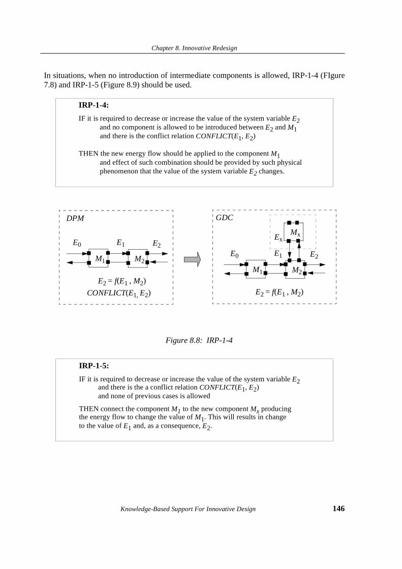
Chapter 8. Innovative Redesign
Knowledge-Based Support For Innovative Design 146
In situations, when no introduction of intermediate components is allowed, IRP-1-4 (FIgure7.8) and IRP-1-5 (Figure 8.9) should be used.
Figure 8.8: IRP-1-4
IRP-1-4:
IF it is required to decrease or increase the value of the system variable E2 and no component is allowed to be introduced between E2 and M1 and there is the conflict relation CONFLICT(E1, E2)
THEN the new energy flow should be applied to the component M1 and effect of such combination should be provided by such physical phenomenon that the value of the system variable E2 changes.
IRP-1-5:
IF it is required to decrease or increase the value of the system variable E2and there is the a conflict relation CONFLICT(E1, E2)and none of previous cases is allowed
THEN connect the component M1 to the new component Mx producing the energy flow to change the value of M1. This will results in change to the value of E1 and, as a consequence, E2.
E2 = f(E1 , M2)
E1E0
M1
E2
M2
Ex
E2 = f(E1 , M2)
E1E0
M1
E2
M2
Mx
CONFLICT(E1, E2)
DPM GDC

Chapter 8. Innovative Redesign
147 Knowledge-Based Support For Innovative Design
Figure 8.9: IRP-1-5
8.4.4 Mapping between function and GPP
To solve a problem with IRP means to identify what GPP can be networked with existingdesign prototype model. This can be done through a mapping between a function defined forGPP.
The mapping involves finding a correspondence between a given description of the functionand a physical structure which would be capable of delivering the function. IRP proposeshow to introduce a new component, however does not specify what component should beintroduced. The task is:
1. To identify a function that has to be fulfilled by a component.
2. To identify constraints.
3. To map the function identified onto a GPP(s) of available GPP knowledge base.
A procedure for mapping is outside the scope of the thesis. However, we should note that itcan be solved
8.4.5 Applicability of Innovative Redesign Principles
One can give numerous examples illustrating how the principles of innovative redesign pre-sented above are widely used in engineering design. However, they were used intuitively bydesigners since no explicit expression of the principles has ever existed apart from InventiveStandards. As a consequence, no formal definition of such principles has been proposed sofar.
E2 = f(E1 , M2)
E1E0
M1
E2
M2
Ex
E2 = f(E1 , M2)
E1E0
M1
E2
M2
Mx
CONFLICT(E1, E2)
DPM GDC
Chapter 8. Innovative Redesign
Knowledge-Based Support For Innovative Design 148
A lack of a general modeling framework that would enable a designer to represent varioustypes of design products in uniform way made it nearly impossible to formulate a reasoningstrategy for a computational, knowledge-based innovative design.
Although the use of some pure AI methods (such as qualitative or case-based reasoning, forinstance) can help with modeling and solving problems within well-defined solution space,we would still be unable to reason about innovative problems without appropriate problem-solving method. For this reason, the efficiency of pure AI methods which are not based ondesign principles would be very low. By defining axioms and drawing a number of designprinciples from them, we thereby introduced a strategy for solving innovative design prob-lems. Therefore, using INDES strategic knowledge it is possible to build a knowledge-basedsystem which will incorporate basic principles of innovative design.
8.5. General model of innovative redesign
8.5.1 Model of innovative redesign
Before performing the process of innovative redesign, a number of decisions has to be madeby a designer. Among them are assumptions that limit the borders of a system to be modeledand assumptions that define the degrees of conceptualization and generalization of a givendesign prototype. During selecting components that has to be included into DPM, a specialattention has to be paid to those objects and energy flows from the outer environment thatinteract or may interact with the system and thus might cause the design conflicts.
After making these decisions, the overall process of innovative redesign consists of the fol-lowing steps:
1. Analysis Part:
1.1. Building a model of part of a selected design product in terms of DPM byidentifying objects of a design prototype with appropriate GPPs from a GPPknowledge base;
1.2. Decomposition of the overall functions performed by GPPs into subfunc-tions;
1.3. Identification of what variable(s) should alter its value to meet the require-ment given represented as a new value of the variable;
1.4. Identification of a pair of conflicting variables through analysis of the DPM;
1.5. Selection of a principle for innovative redesign according to the limitationson the new components use defined for a problem;
Chapter 8. Innovative Redesign
149 Knowledge-Based Support For Innovative Design
1.6. Identification of a blank GDC according to the selected innovative redesignprinciple;
1.7. Identification of a function that should be provided by a GPP.
2. Synthesis Part:
2.1. Mapping the function identified for a GPP that can eliminate the conflictonto the available GPP(s);
2.2. Checking against the boundary conditions and integrity constraints to filter-ing out those specific GPP(s) that may not be incorporated into the DPM.
2.3. Building a GDC by instantiating the values of variables of introducedGPP(s).
As seen, our model of innovative redesign does not propose a means for the evaluation ofobtained solutions. Assuming that the design process might result in a number of alternativeGDCs, each of which meets the given requirement and does not contain conflicting values ofparameters, their applicability should be verified against more specific limitations manually(for reasons see section 8.7). Our task was to ensure that the obtained solutions presented inform of GDCs are physically realisable.
8.6. Case study: Application of IRP
To explain how the principles for structure extension can be used in practise, let us give anexample.
A part of a system for outdoor water supply consists of two material components: a waterflow and a steel pipe. During warm seasons, the value of water pressure is not enough todamage to the walls.
A problem occurs during cold seasons when a phase transition of water into ice takes place.If the pipe is not thermoprotected then water freezes and the value of pressure of expandingice reaches a maximal allowed value of a mechanical stress limit for material of which thepipe is made thus causing growth of internal mechanical stresses inside the pipe wall. Elasticdeformation of the wall turns out to be irreversible lattice expansion which results in slip ofwhole lattice areas occurring along the direction of maximum shear stresses.
According to a general procedure of innovative redesign, the system consisting of water flowand the pipe can be modeled as two interacting physical phenomena: phenomena of phasetransition and phenomena of material deformation. As a conclusion, the problem model canbe represented as a DPM consisting of two connected GPPs.The phenomena of phase transi-
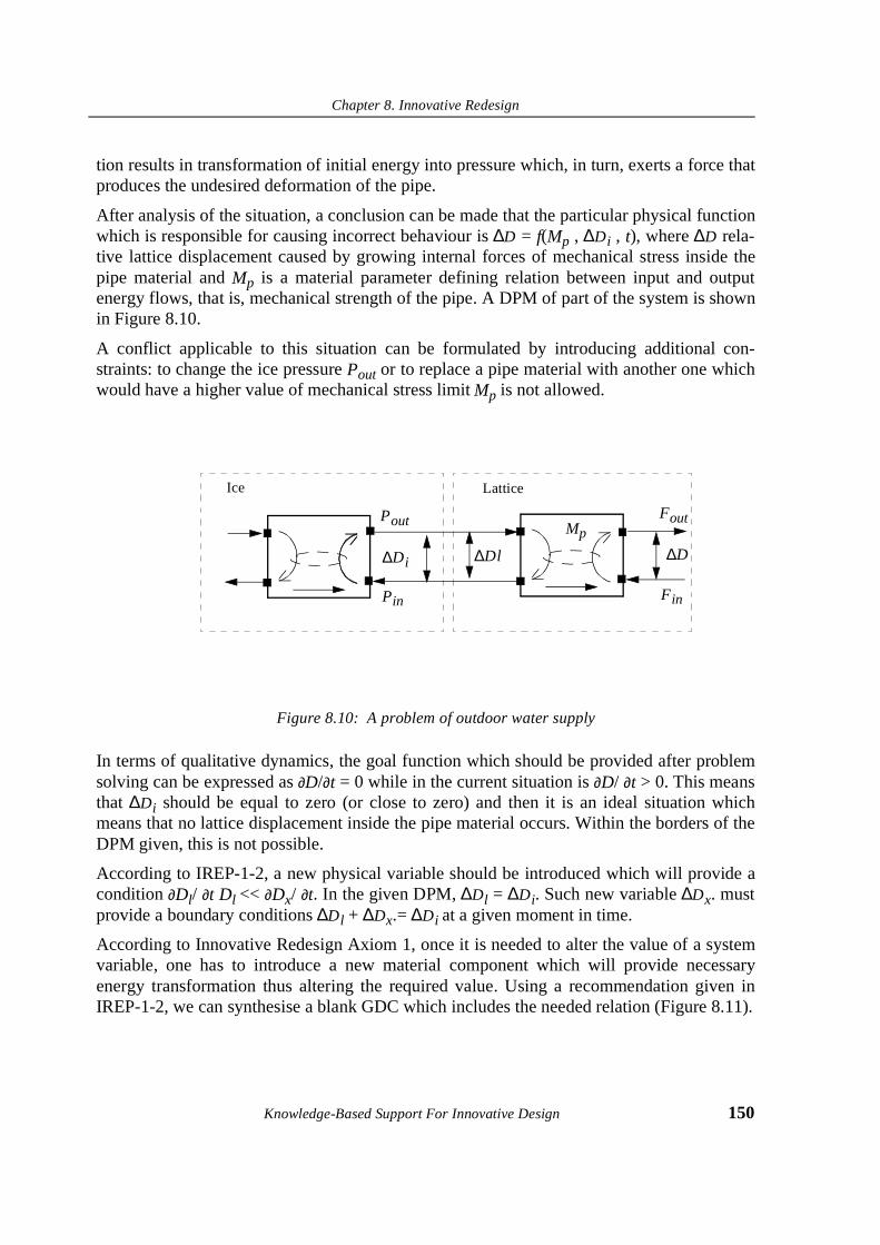
Chapter 8. Innovative Redesign
Knowledge-Based Support For Innovative Design 150
tion results in transformation of initial energy into pressure which, in turn, exerts a force thatproduces the undesired deformation of the pipe.
After analysis of the situation, a conclusion can be made that the particular physical functionwhich is responsible for causing incorrect behaviour is ∆D = f(Mp , ∆Di , t), where ∆D rela-tive lattice displacement caused by growing internal forces of mechanical stress inside thepipe material and Mp is a material parameter defining relation between input and outputenergy flows, that is, mechanical strength of the pipe. A DPM of part of the system is shownin Figure 8.10.
A conflict applicable to this situation can be formulated by introducing additional con-straints: to change the ice pressure Pout or to replace a pipe material with another one whichwould have a higher value of mechanical stress limit Mp is not allowed.
Figure 8.10: A problem of outdoor water supply
In terms of qualitative dynamics, the goal function which should be provided after problemsolving can be expressed as ∂D/∂t = 0 while in the current situation is ∂D/ ∂t > 0. This meansthat ∆Di should be equal to zero (or close to zero) and then it is an ideal situation whichmeans that no lattice displacement inside the pipe material occurs. Within the borders of theDPM given, this is not possible.
According to IREP-1-2, a new physical variable should be introduced which will provide acondition ∂Dl/ ∂t Dl << ∂Dx/ ∂t. In the given DPM, ∆Dl = ∆Di. Such new variable ∆Dx. mustprovide a boundary conditions ∆Dl + ∆Dx.= ∆Di at a given moment in time.
According to Innovative Redesign Axiom 1, once it is needed to alter the value of a systemvariable, one has to introduce a new material component which will provide necessaryenergy transformation thus altering the required value. Using a recommendation given inIREP-1-2, we can synthesise a blank GDC which includes the needed relation (Figure 8.11).
Pout
Pin
∆Di
Fout
Fin
∆D
Ice Lattice
Mp
∆Dl
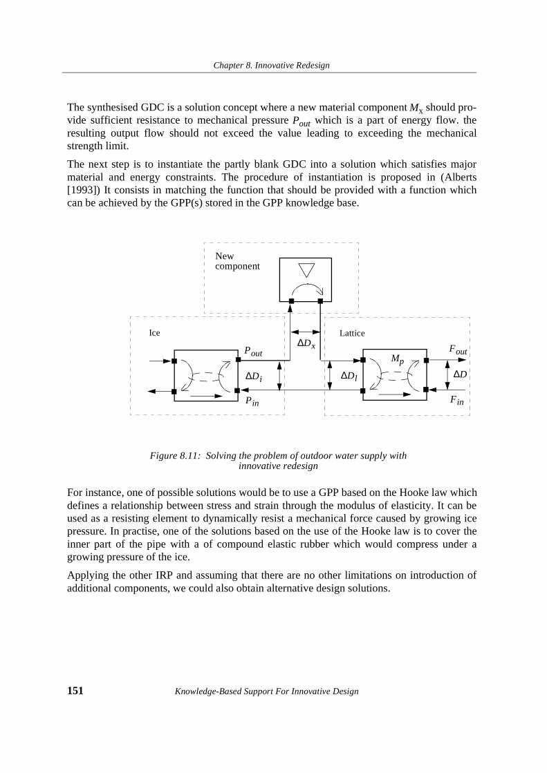
Chapter 8. Innovative Redesign
151 Knowledge-Based Support For Innovative Design
The synthesised GDC is a solution concept where a new material component Mx should pro-vide sufficient resistance to mechanical pressure Pout which is a part of energy flow. theresulting output flow should not exceed the value leading to exceeding the mechanicalstrength limit.
The next step is to instantiate the partly blank GDC into a solution which satisfies majormaterial and energy constraints. The procedure of instantiation is proposed in (Alberts[1993]) It consists in matching the function that should be provided with a function whichcan be achieved by the GPP(s) stored in the GPP knowledge base.
Figure 8.11: Solving the problem of outdoor water supply with innovative redesign
For instance, one of possible solutions would be to use a GPP based on the Hooke law whichdefines a relationship between stress and strain through the modulus of elasticity. It can beused as a resisting element to dynamically resist a mechanical force caused by growing icepressure. In practise, one of the solutions based on the use of the Hooke law is to cover theinner part of the pipe with a of compound elastic rubber which would compress under agrowing pressure of the ice.
Applying the other IRP and assuming that there are no other limitations on introduction ofadditional components, we could also obtain alternative design solutions.
Pout
Pin
∆Di
Fout
Fin
∆D
Ice Lattice
Mp
∆Dx
∆Dl
New component

Chapter 8. Innovative Redesign
Knowledge-Based Support For Innovative Design 152
4.7. Innovative redesign and ICAID
One of the objectives of AI research is to find such adequate methods to model and representknowledge about real world that an AI system incorporating these models and knowledgewould be able to automatically reason about new problems. Such reasoning process results infinding and evaluating solutions to the problems. With respect to innovative design, the Intel-ligent Computer-Aided Innovative Design (ICAID) system should be able to analyse prob-lems defined within multiple constraint space and generate physically feasible solutionspresented in design terms.
Apart from that, the ICAID system should be capable of multi-criteria evaluation of pro-posed solutions. As we already mentioned earlier, to achieve this is nearly impossible at thecurrent level of AI since we are still unable to relate all specific and commonsense knowl-edge the designer reasons with about design products. This problem addresses to a large dif-ficulty to foresee and explicitly represent every particular relation occurring within thesystem constituting the product as well as between the system and its outer environment.
Apart from this, many of designer’s decisions are influenced by such situation-dependent cri-teria as manufacturability, ergonomics, recyclability, costs and so forth. All information con-cerning a specific design and its outer environment might thus not be available unless asolution concept has been proposed. For this reason, a model of the product may be regardedas consistent only under certain assumptions made by a designer. If, however, a solutionobtained on the basis of previously made assumptions is invalid, these assumptions should beretracted from the product description. In AI, such type of problems dealing with difficulty toidentify and update human’s beliefs addresses to the so-called Frame Problem (Crockett[1993]) which is still to be solved. It was not planned within the framework of INDESresearch, and we therefore was left it out of the scope of this thesis.
Nevertheless, we believe that using INDES as a formal approach to structuring both TRIZand physical knowledge, those parts of ICAID system that would support generation andevaluation of new design concepts by reasoning from physical knowledge are possible todevelop. INDES proposes a formal background for conducting a design product analysis,synthesising new design concepts and evaluating the physical feasibility of the concepts gen-erated. Those parts of ICAID which would support reasoning processes about decompositionof problems as well as multicreteria solution evaluation are left out to the responsibility of ahuman designer.
4.8. Summary
In this chapter, we proposed a framework for modeling innovative redesign based on designconflict elimination. To eliminate conflicts, the principles for innovative redesign were intro-duced. We only presented a part of all possible principles for innovative redesign.

Chapter 8. Innovative Redesign
153 Knowledge-Based Support For Innovative Design
The principles were drawn from two axioms for innovative redesign, which, in turn, wereformulated on the basis of general properties of interacting physical entities and the trend of“complexity growth - complexity reduction”.
Based on the introduced concepts, a general model of innovative redesign was proposed. Themodel establishes consistent and formal methodology which relates INDES object and strate-gic knowledge. Finally, we discussed a possibility to incorporate the INDES model of inno-vative redesign into a system for Intelligent Computer-Aided Innovative Design.

Knowledge-Based Support For Innovative Design 154

Chapter 9. Case Study
155 Knowledge-Based Support For Innovative Design
Chapter 9. Case Study
9.1. Introduction
This chapter presents a case study where the proposed framework is used to solve a realdesign problem in combination with function analysis technique for finding and formulatingproblems. Cordis N.V. (a Johnson & Johnson Company, Roden, The Netherlands) gener-ously agreed to participate in the experiment and to provide all the necessary information.The company designs an manufactures a stent delivery system - a small metal tube insertedinto an artery to treat a Coronary Artery Disease. This design is known as Palmaz-SchatzStent.
The goal of the experiment was not to find a novel, feasible and patentable solution to theproblem which is unknown yet but to verify if the approach proposed in the book has a prac-tical value.
Specific technical details were omitted to make the description more structured and clear.
9.2. Problem Description
A coronary stent is a small, slotted, stainless steel tube mounted on a balloon catheter (Figure9.1). It is introduced into the artery just after balloon angioplasty and is positioned at the siteof the obstruction.
When the balloon is inflated with the liquid, the stent expands and is pressed against theinner walls of the artery. After the balloon is deflated and removed, the stent remains inplace, keeping the artery open.

Chapter 9. Case Study
Knowledge-Based Support For Innovative Design 156
The stent is a permanent implant that remains in the artery. It helps hold the artery open,improves blood flow, and relieves symptoms of Coronary Artery Disease.
The list of technical parameters and design features of the stent ispresented in Table 10.1
Figure 9.1: Palmaz-Schatz Stent
7$%/(������Technical features of the stent
Design Balloon expandible
Configuration Slotted tube
Material Stainless steel
Strut diameter (mm/inch) 0.08/0.003
Length (mm) 15
Metal surface area (%) 12
Maximum guidewire (in.) 0.014
Minimum guide internal diameter (mm) 0.084
Expanded diameter (mm) 3.0-5.0
Deployment pressure (atm.) 6-8

Chapter 9. Case Study
157 Knowledge-Based Support For Innovative Design
9.3. Problem model
Before formulating a problem, a function analysis of a stent delivery system was conductedaccordingly the rules formulated in (Litvin and Guerassimov, 1989). Apart from the compo-nents which belong to the technical system “stent” and the stent delivery system, those com-ponents of the outer system which interact with the stent delivery system during theoperation were included into the model. Among these components were the blood vessel(artery) and the blood stream. A part of the function model of the system which includesprincipal components is presented in Figure 9.2.
Figure 9.2: Function Diagram of the stent delivery system.
The next step was to analyse if the model contains the undesired, harmful or insufficientinteractions. To do this, a degree of performance each function was matched against thesecriteria. The results are presented in the table 9.2
Stent
balloon
blood vessel
liquid blood stream
expandsblocks
expands
opens
keeps open
damages
holds
carries
damages
holds

Chapter 9. Case Study
Knowledge-Based Support For Innovative Design 158
Analysis of the table indicates that four problems can be formulated for the stent deliverysystem - positions 3,7,8,9.
For further work, we formulated the following tasks:
1. To solve a particular problem. The problem of damaging to the balloon by the stentduring the opening (position 3) was chosen.
2. To see if any other physical principles can be proposed to design a new stent open-ing system.
9.4. A Design Prototype Model
The function model presented in the previous section was translated into the INDES-modelof a design prototype presented in Figure 9.3. The DPM of the stent delivery system includesfour components: the liquid, the balloon, the stent and the blood vessel as well as correspond-ing energy flows between the components.
TABLE 9.2: Analysis of the functions
No. Component Function Component Performance
1 stent opens blood vessel adequate
2 stent keeps open blood vessel adequate
3 stent damages to balloon harmful
5 blood vessel holds stent adequate
6 blood vessel carries blood stream adequate
7 blood vessel damages to balloon harmful
8 balloon holds stent insufficient
9 balloon blocks blood stream harmful
10 balloon expands stent adequate
11 liquid expands balloon adequate
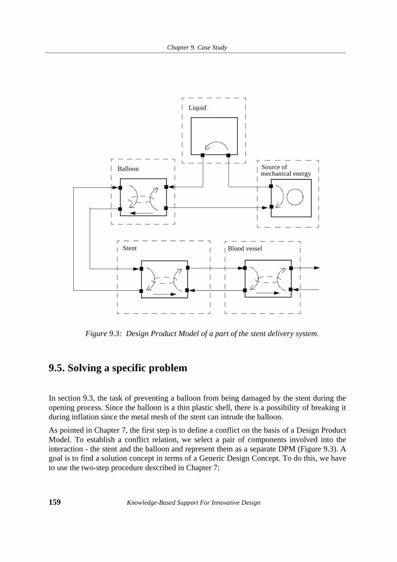
Chapter 9. Case Study
159 Knowledge-Based Support For Innovative Design
Figure 9.3: Design Product Model of a part of the stent delivery system.
9.5. Solving a specific problem
In section 9.3, the task of preventing a balloon from being damaged by the stent during theopening process. Since the balloon is a thin plastic shell, there is a possibility of breaking itduring inflation since the metal mesh of the stent can intrude the balloon.
As pointed in Chapter 7, the first step is to define a conflict on the basis of a Design ProductModel. To establish a conflict relation, we select a pair of components involved into theinteraction - the stent and the balloon and represent them as a separate DPM (Figure 9.3). Agoal is to find a solution concept in terms of a Generic Design Concept. To do this, we haveto use the two-step procedure described in Chapter 7:
Stent Blood vessel
Liquid
Source of mechanical energy
Balloon
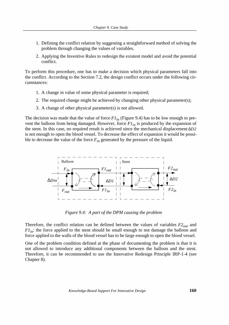
Chapter 9. Case Study
Knowledge-Based Support For Innovative Design 160
1. Defining the conflict relation by suggesting a straightforward method of solving theproblem through changing the values of variables.
2. Applying the Inventive Rules to redesign the existent model and avoid the potentialconflict.
To perform this procedure, one has to make a decision which physical parameters fall intothe conflict. According to the Section 7.2, the design conflict occurs under the following cir-cumstances:
1. A change in value of some physical parameter is required;
2. The required change might be achieved by changing other physical parameter(s);
3. A change of other physical parameter(s) is not allowed.
The decision was made that the value of force F1in (Figure 9.4) has to be low enough to pre-vent the balloon from being damaged. However, force F1in is produced by the expansion ofthe stent. In this case, no required result is achieved since the mechanical displacement ∆D2is not enough to open the blood vessel. To decrease the effect of expansion it would be possi-ble to decrease the value of the force Fin generated by the pressure of the liquid.
Figure 9.4: A part of the DPM causing the problem
Therefore, the conflict relation can be defined between the values of variables F2out andF1in: the force applied to the stent should be small enough to not damage the balloon andforce applied to the walls of the blood vessel has to be large enough to open the blood vessel.
One of the problem condition defined at the phase of documenting the problem is that it isnot allowed to introduce any additional components between the balloon and the stent.Therefore, it can be recommended to use the Innovative Redesign Principle IRP-1-4 (seeChapter 8).
F1out
F1in
Fin
Fout
∆Din ∆D1
F2out
F2in
∆D2
Balloon Stent

Chapter 9. Case Study
161 Knowledge-Based Support For Innovative Design
After substituting the generic variables in this rule, we obtain the specific formulation of therule:
IRP-1-4:
IF it is required to increase the value of the system variable F2out and no component is allowed to be introduced between F2out and the stent and there is the conflict relation CONFLICT(F2out, F1in)
THEN the new energy flow should be applied to the component stent and effect of such combination should be provided by such physical phenomenon that the value of the system variable F2out increases.
IRP-1-4:
IF it is required to decrease or increase the value of the system variable E2 and no component is allowed to be introduced between E2 and M1 and there is the conflict relation CONFLICT(E1, E2)
THEN the new energy flow should be applied to the component M1 and effect of such combination should be provided by such physical phenomenon that the value of the system variable E2 changes.
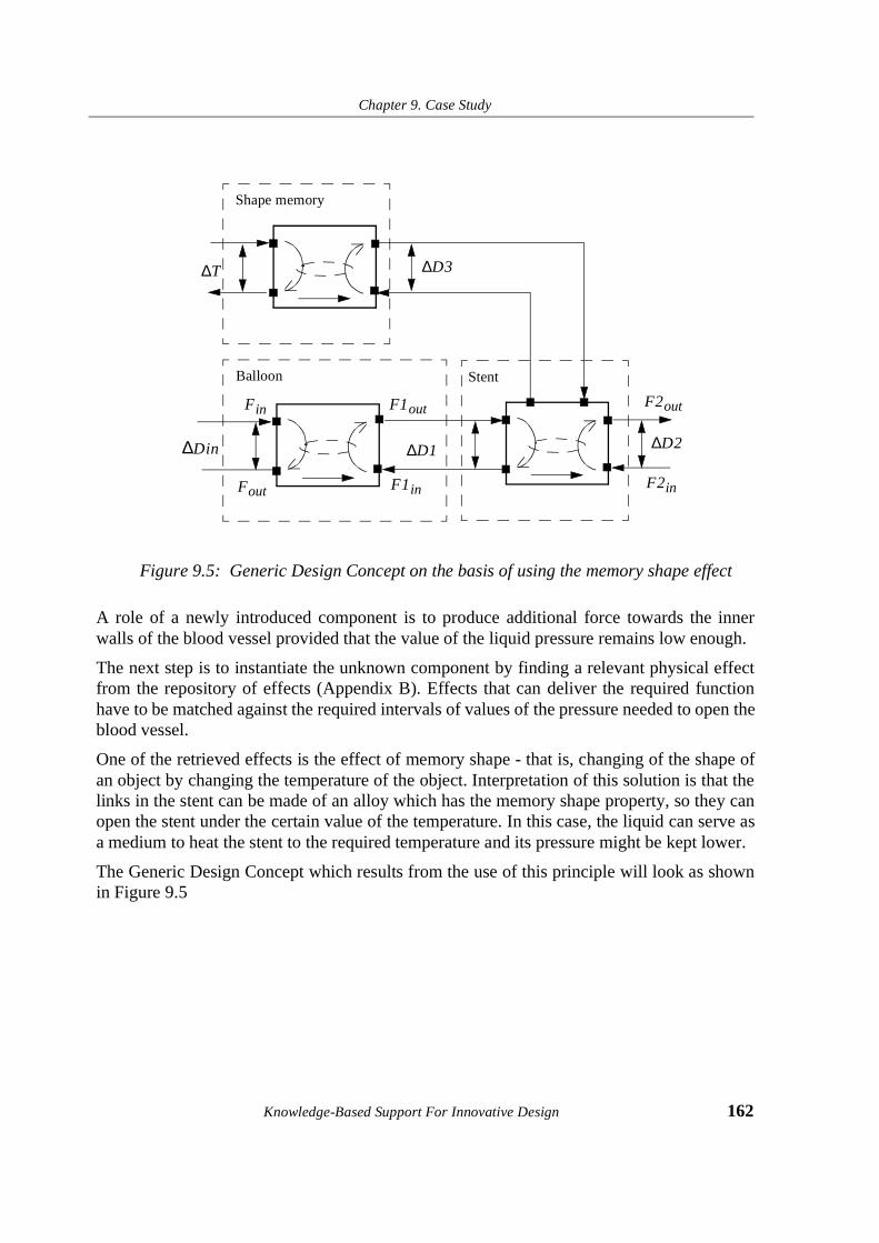
Chapter 9. Case Study
Knowledge-Based Support For Innovative Design 162
Figure 9.5: Generic Design Concept on the basis of using the memory shape effect
A role of a newly introduced component is to produce additional force towards the innerwalls of the blood vessel provided that the value of the liquid pressure remains low enough.
The next step is to instantiate the unknown component by finding a relevant physical effectfrom the repository of effects (Appendix B). Effects that can deliver the required functionhave to be matched against the required intervals of values of the pressure needed to open theblood vessel.
One of the retrieved effects is the effect of memory shape - that is, changing of the shape ofan object by changing the temperature of the object. Interpretation of this solution is that thelinks in the stent can be made of an alloy which has the memory shape property, so they canopen the stent under the certain value of the temperature. In this case, the liquid can serve asa medium to heat the stent to the required temperature and its pressure might be kept lower.
The Generic Design Concept which results from the use of this principle will look as shownin Figure 9.5
F1out
F1in
Fin
Fout
∆Din ∆D1
F2out
F2in
∆D2
Balloon Stent
∆T
Shape memory
∆D3
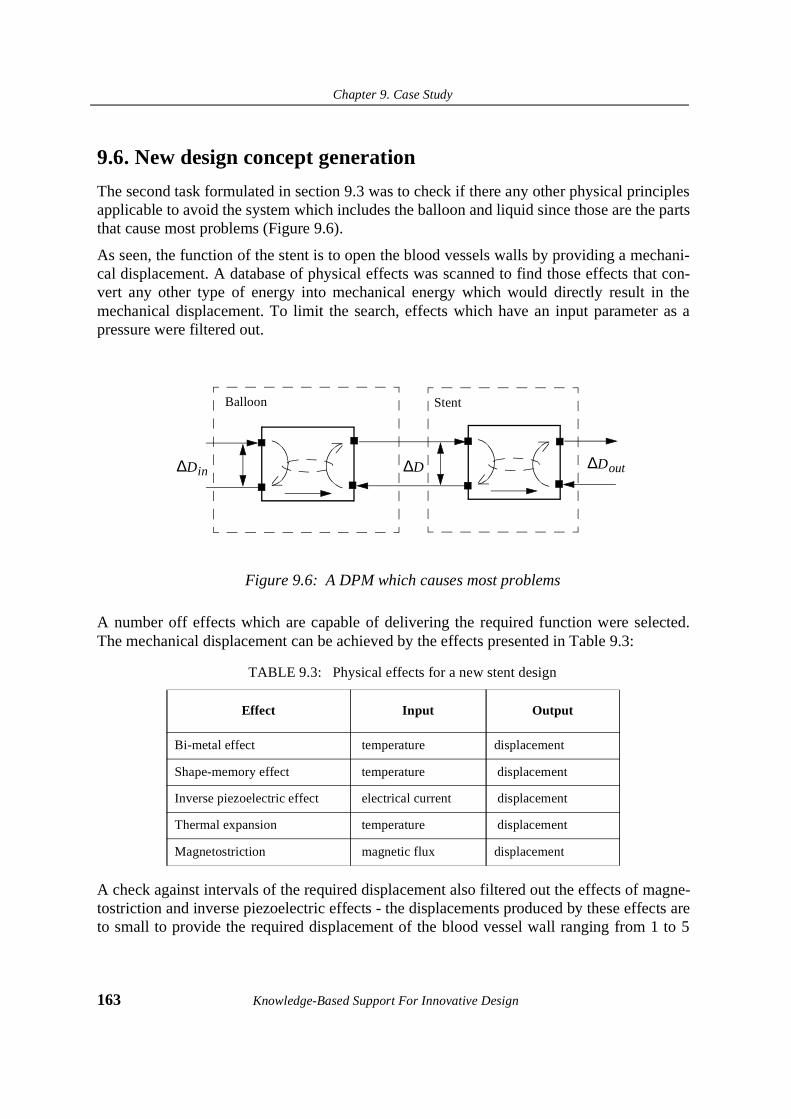
Chapter 9. Case Study
163 Knowledge-Based Support For Innovative Design
9.6. New design concept generation
The second task formulated in section 9.3 was to check if there any other physical principlesapplicable to avoid the system which includes the balloon and liquid since those are the partsthat cause most problems (Figure 9.6).
As seen, the function of the stent is to open the blood vessels walls by providing a mechani-cal displacement. A database of physical effects was scanned to find those effects that con-vert any other type of energy into mechanical energy which would directly result in themechanical displacement. To limit the search, effects which have an input parameter as apressure were filtered out.
Figure 9.6: A DPM which causes most problems
A number off effects which are capable of delivering the required function were selected.The mechanical displacement can be achieved by the effects presented in Table 9.3:
A check against intervals of the required displacement also filtered out the effects of magne-tostriction and inverse piezoelectric effects - the displacements produced by these effects areto small to provide the required displacement of the blood vessel wall ranging from 1 to 5
TABLE 9.3: Physical effects for a new stent design
Effect Input Output
Bi-metal effect temperature displacement
Shape-memory effect temperature displacement
Inverse piezoelectric effect electrical current displacement
Thermal expansion temperature displacement
Magnetostriction magnetic flux displacement
∆Din
Balloon Stent
∆Dout∆D

Chapter 9. Case Study
Knowledge-Based Support For Innovative Design 164
mm. Nevertheless, the effects of bi-metal and shape memory effects can be used to design anew system for opening the stent.
9.7. Conclusions
As shown above, the use of the proposed framework can be used both for problem solvingand synthesis of new design concepts. Discussions with the research engineers from CordisN.V. indicated that the concepts generated are worth to consider, however, it is unclear whatwill be the costs of realizing the solutions, however this question resides outside the scope ofINDES research.
In addition, we found information that the idea based on the shape memory effect was pro-posed recently as a concept for future stent designs, but we could not find a reference to theuse of bi-metals .
However, the major result from the experiment was shortening the cycle of the conceptualdesign phase by using the INDES framework. Although not implemented yet as a computer-based system, even applied in a “manual” way, the approach appeared to be very effective tomodel problems and generate solution concepts within a short time. The whole process tookthree days - from documenting the problem to generating a number of solution concepts.

Chapter 10. Summary and Conclusions
165 Knowledge-Based Support For Innovative Design
Chapter 10. Summary and Conclusions
10.1. Summary
A central question we attempted to answer in the book was: “Is it possible to organize anautomated knowledge-based support for the early phases of engineering design?”
In order to obtain the answer we conducted a research which resulted in the development ofINDES - an integrated framework for uniform modelling of domain and strategic knowledgefor innovative design. As it had become clear soon after initiating the research, it was notpossible to create INDES by only using techniques and methods of Artificial Intelligence andKnowledge-based modelling. We faced a situation when we had to construct a new designtheory since no consistent theoretical foundation for innovative engineering design had everexisted.
To construct such the theory, we used TRIZ, a Russian Theory of Inventive Problem Solv-ing. To make the reader of the book become familiar with TRIZ, we provided an introduc-tion to the Altshuller’s approach (Chapter 3). However, TRIZ resulted from empirical studiesand lacks a formal background. While being useful as a tool for “manual” work, TRIZ tech-nique are too abstract and general to be represented in formal way. Since no formal back-ground have ever been proposed to model TRIZ apart from several unsuccessful attempts,the goal of INDES was to restructure TRIZ knowledge and to develop a sharable domain-independent ontology for modeling knowledge for innovative design.
As a result, we defined several key INDES concepts on the basis of TRIZ. Among them arethe concept of a conflict for finding and formulating problems, substance-field modelling,the approach to representing physical effects.
Chapter 10. Summary and Conclusions
Knowledge-Based Support For Innovative Design 166
We also explained and demonstrated our approach to structure knowledge for innovativeengineering design which was used to develop formal methods for modeling.
The second part of the monograph (Chapters 5-8) introduced and explained major INDES conceptsand underlying theory of innovative engineering design.
The case study presented in Chapter 9 demonstrated a practical applicability of INDES for asynthesis of new design concepts and solving specific design problems. In addition, the casestudy helped to formulate a number of guidelines for further research.
10.2. Contribution of the research.
INDES defines sharable object and strategic knowledge concepts for innovative design andproposes a new model of conceptual design based on sharable physical knowledge. Belowwe outline a number of INDES results which can be regarded as our contribution to AI andDesign research.
1. To model and represent basic information necessary for tasks of analysis and syn-thesis during conceptual design, INDES introduced a sharable knowledge conceptlabelled Generic Physical Principle defined on the basis of System Theory and net-work modelling. Generic Physical Principle is a black-box model of a physical phe-nomenon viewed as energy transformation process. Generic Physical Principleexplicitly incorporates both parameters of energy flows and material aspects ofcomponents constituting any physical phenomenon.
2. INDES regards conceptual engineering design as a procedure of synthesis from thephysical principles. Such view is based on the fact that two and more generic physi-cal principles can be combined to a network. The resulting network is labelled aGeneric Design Concept which is a compound INDES concept. The physical valid-ity of a Generic Design Concept is provided by checking against boundary condi-tions following from the law of energy preservation.
3. All physical effects can be modelled as generic physical principles and organized toa knowledge base.
4. It is possible to organize a design from generic physical principles by decomposinggiven specifications and matching the required function and a predefined functionwhich can be delivered by a particular generic physical principle.
5. In order to enable modelling of existing design products in terms of INDES, we pro-posed to model a selected design product as a Design Prototype Model. A DesignPrototype Model is an instance of a Generic Design Concept obtained by constrain-

Chapter 10. Summary and Conclusions
167 Knowledge-Based Support For Innovative Design
ing intervals of values of variables. Given a Design Prototype Model, one can rea-son about what conflicts may arise if the designer wishes to change a design productin innovative way.
6. We defined the key concept for problem finding and formulation as a conflict. Twotypes of behaviour of design products are distinguished: correct behaviour, when allvalues of system and form variables are within the required intervals; and violatedbehaviour, when a value of some system or form variable does not belong to thespecified interval. Violated behaviour results from the designer’s wish to change aparameter of a Design Prototype Model which is related to another parameter.Therefore, if no change of the value of the variable is possible without violating theoverall behaviour, a conflict between two parameters takes place.
7. A process of redesigning a Design Product Model by conflict elimination is labelled“Innovative Redesign”. INDES defines two axioms of Innovative Redesign basedon today’s state-of-the-art in physics research.
8. Based on the axiomatic approach, a number of Innovative Redesign Principles wasproposed. The principles specify how a Design Prototype Model should be changedin such a way that no violation of behaviour will occur. We introduced two BasicInventive Redesign Principles: Extension Principle which recommends to solveproblems by adding new components to the existing system and Replacement Prin-ciple, which proposes to replace a physical principle behind a system componentthat does not meet new design requirements and specifications.
9. A general model of INDES-based design was proposed.
10.3. Conclusions
We believe that the INDES framework can be used to build the knowledge-intensive CAIDsystem supporting the development of new product concepts. From our point of view, amongthe principal advantages of INDES are:
1. INDES object knowledge is based on objective physical laws.
2. INDES strategic knowledge is based on axiomatic approach.
Incorporating basic TRIZ principles, INDES eliminates inconsistency and informality ofTRIZ and makes it possible to organize a reasoning process with formal models of designproducts.
Among the limitations of INDES are inability to reason about geometrical information and re-striction to energy-transforming systems.

Chapter 10. Summary and Conclusions
168 Knowledge-Based Support For Innovative Design
10.4. Further research
The ultimate goal is to develop a system for automated generation of new design solutions,we believe the following problems have to be solved:
1. A comprehensive knowledge base of physical effects has to be developed that willcontain all physical effects represented in INDES terms.
2. A proposed collection of Innovative Redesign Principles (Chapter 8) has to berefined and added with more principles. This can be done by further analysing theTRIZ collection of Inventive Standards and selection of those rules which can berepresented in terms of INDES strategic knowledge.
3. Since INDES misses an analytical part, a new framework for conceptual analysis ofexisting design products has to be developed to localize and formulate design prob-lems that can be further solved with INDES. We believe that such framework has tobe based on the function approach to the products analysis.
4. A new intermediary format for data representation has to be developed which willmake it possible to automatically represent information about specific design com-ponents collected by a designer in terms of generic physical principles. A problemof identification of the specific design components with generic physical principleshas also to be solved.
5. One of the remaining problems is how to interpret the solutions obtained by auto-mated generation in specific design terms. In other words, it is necessary to under-stand how to instantiate proposed concepts into specific develop machines andmachine parts. A cross-domain search for existing design solutions will not alwayshelp since a specific solution might not be available at all. Therefore, the researchhas to be focused on establishing links between INDES-based system and existingCAD systems.

Bibliography
169 Knowledge-Based Support For Innovative Design
Bibliography
V. Akman, P.J.V ten Hagen, & T. Tomiyama [1990], “A fundamental and theoreticalframework for intelligent CAD Systems”, Computer-Aided Design, 22(6), 368-376.
V. Akman & P.J.W. ten Hagen [1989], “The power of Physical Representations”, AIMagazine, Fall 1988, 49-65.
L.K. Alberts, P.M. Wognum & N.J.I. Mars [1991], “Design as a science instead of art”,University of Twente, Department of Computer Science, Enschede, TheNetherlands.
L.K. Alberts [1993a], “YMIR: a domain-independent ontology for the formal representationof engineering-design knowledge”, in Proceedings of IFIP Workshop on FormalDesign Methods for CAD, June 16-19, 1993, Tallinn, Estonia, 139-152.
L.K. Alberts [1993b], YMIR: an Ontology for Engineering Design, Ph.D Thesis, Universityof Twente, Enschede, The Netherlands.
G.S. Altshuller & R.V. Shapiro [1956], “About technology of creativity”, Questions ofPsychology, 6, 37-49
G.S. Altshuller [1969], Algorithm of Invention, Moscowskiy Rabochy (in Russian), Moscow.
H. Altshuller [1984], Creativity as an Exact Science, Gordon and Breach ScientificPublishers, New York.
G.S. Altshuller [1986], To Find an Idea: Introduction into the Theory of Inventive ProblemSolving, Nauka, Novosibirsk (in Russian).

Bibliography
Knowledge-Based Support For Innovative Design 170
G.S. Altshuller [1988]. “A Brief Report on the Theory of Inventive Problem Solving”,Typescript, Petrozavodsk, Russia.
G.S. Althsuller, B.L. Zlotin, A.V. Sussman & V.I. Filatov [1989], Search for new ideas: FromInsight to Technology (Theory and Practise of Inventive Problem Solving), , KarteMoldaveniaske, Kishinev (in Russian).
F. Amirouche [1994], Computer Aided Design and Manufacturing, Prentice Hall.
K. Andersson [1993], “A Vocabulary for Conceptual Design - Part of a Design Grammar”, inProceedings of IFIP Workshop on Formal Design Methods for CAD, June 16-19,1993, Tallinn, Estonia, 139-152.
L. Apelskog Killander [1996], “Injection-Molding Inserts For Prototype Tools Made WithFree Form Fabrication”, Ph.D. Thesis, Department of Manufacturing Systems,Royal Institute of Technology, Stockholm.
T. Arciszewski [1988], “ARIZ-77: A Method of Innovation Design”, Design Methods andTheories 22(2).
W. Beitz & K.-H. Kuttner (eds) [1994], Dubbel Handbook of Mechanical Engineering,Springer-Verlag, London.
S. Bhatta & A. Goel [1994], “Innovation in analogical design: a model-based approach”, inProceedings Artificial Intelligence in Design’94, August 15-18, Lausanne,Switzerland, J.S. Gero and F. Sudweeks, eds., Kluwer Academic Publishers, 57-74.
E. de Bono [1992], Serious Creativity, Harper Collins, New York.
G. Boothroyd [1987], “Design For Assembly - The Key Design for Manufacture”, TheInternational Journal of Manufacturing Technology, 2, 3-11.
P. Borst, J.M. Akkermans, A. Pos & J.L. Top [1995] “The PhysSys Ontology for PhysicalSystems”, in Working Papers of the Ninth International Workshop on QualitativeReasoning, 16-19 May 1995, Amsterdam, The Netherlands, 11-21.
J. Braham [1995], “Inventive ideas grow with ‘Triz.’”, Machine Design. Vol. 67 No. 18.October 12.
D. Brown & B. Chandrasekaran [1985], “Expert system for a class of mechanical designactivity”, in Knowledge engineering in computer-aided design, J.S. Gero, ed.,North-Holland.
Bibliography
171 Knowledge-Based Support For Innovative Design
K. Clibbon & E. Edmonds [1995], “Strategic knowledge in computational models of creativedesign”, in Preprints of the 3rd International. Roundtable Conference onComputational Models of Creative Design, J.S. Gero, M.L. Maher & F.Sudweeks, eds., 3-7 December 1995, Heron Island, Queensland, Australia, 319-343.
L. Crockett, [1994]. The Turing Test and the Frame Problem: AI’s Mistaken Understandingof Intelligence. Ablex, Norwood, New Jersey.
I.G. Devoino [1993], “Complication of Technical Systems”, in Proc. of ICED-93,International Conference on Engineering Design, The Hague, The Netherlands.
F. Dikker, G.B. Leemeijer, P.M. Wognum, & N.J.I. Mars [1992], “Towards computer-supported creative design based on Altshuller's theory of inventive problemsolving”, Memoranda Informatica 92-49, Enschede, Univeristy of Twente, TheNetherlands.
M. Dyer, M. Flowers & J. Hodges [1986], “EDISON: An engineering design invention systemoperating naively”, in Proceedings of the First International Conference onApplication of Artificial Intelligence in Engineering Problems, D. Sriram and R.Adey, eds., Springer Verlag, Southampton, UK, 327-341.
K. Engelmaier [1910], Theory of Creativity, Severo-Zapad, St. Petersburgh, Russia (inRussain).
V.R. Fey, E.I. Rivin, I.M. Vertkin [1994], “Application of the Theory of Inventive ProblemSolving to Design and Manufacturing Systems”, Annals of the CIRP 43(1).
K.D. Forbus [1984], “Qualitative Process Theory”, Artificial Intelligence, 24, 85-168.
J.S. Gero [1994], “Towards a model of exploration in computer-aided design”, in FormalDesign Methods for CAD, J.S. Gero & E. Tyugu, eds, Elsevier, 315-316.
V.V. Glasunov [1993], Synthesis of Novel Technical Devices, Method, Moscow.
G.L. Gleg [1960], Design of Design, Cambridge University Press, New York.
A. Goel [1989], “Integration of Case-Based Reasoning and Model-Based Reasoning forAdaptive Design Problem Solving”, PhD thesis, The Ohio State University, Ohio,USA.
Yu. V. Gorin [1973], “A Pointer to Physical Effects”, Typescrypt.
T.R. Gruber [1993], “A translation approach to portable ontology specifications”, KnowledgeAcquisition, 5(2), 199-220.
Bibliography
Knowledge-Based Support For Innovative Design 172
T.R. Gruber & G.R. Olsen [1994] “An ontology for Engineering Mathematics”, inProceedings of the Fourth International Conference on Principles of KnowledgeRepresentation and Reasoning, Gustav Stresemann Institut, Bonn, Germany,Morgan Kaufmann.
T. Gruber, J. Tenebaum & J. Weber [1992], “Toward a Knowledge Medium for CollaborativeProduct Development”, in Proceedings of the Second International Conferenceon Artificial Intelligence in Design, J.S. Gero, ed., June 22-25 1992, Pittsburg,USA, Kluwer Academic Publishers.
L. Harrisberger [1966], Engineermanship: A Philosophy of Design, Brooks/Cole, Belmont.
B. Hayes-Roth, Waterman & D. Lenat [1983], “Building Expert Systems”.
P.H. Hill [1970], The Science of Engineering Design, Holt, Rinehart and Winston, New York.
J.H. Holland [1975], Adaptation in Natural and Artificial Systems: An Introductory Analysiswith Applications to Biology, Control and Artificial Intelligence, University ofMichigan Press, Ann Arbor.
K. Holt.[1992], “Computer-aided creativity in engineering design”, Journal of EngineeringDesign, 4(4), 371-376
V. Hubka & W. Eder [1988], Theory of technical systems, Springer-Verlag, Berlin,Heidelberg.
M. Ishi, T. Tomiyama & H. Youshikava [***], “A synthetic reasoning method for conceptualdesign”, in Towards Worlds Class Manufacturing, M. Wozny & G. Olling, eds.,Elsevier Science, North-Holland.
M. Ishi, T. Sekiya & T. Tomiyama [1995], “A Very Large-Scale Knowledge Base for theKnowledge Intensive engineering framework”, in Towards Very LargeKnowledge Bases, N.J.I Mars, ed., IOS Press, 123-131.
Y. Iwasaki, R. Fikes, M. Vescovi, and B. Chandrasekaran. [1993], “How Things are Intendedto Work: Capturing Functional Knowledge in Device Design.”, in Proceedings ofthe International Joint Conference on Artificial Intelligence, Chambery, France.
J.C. Jones [1981], Design methods: seeds of human futures, Wiley and Son, New York.
D.C. Karnopp, D.L. Margolis & R.C. Rosenberg [1990], System Dynamics: A UnifiedApproach, John Wiley & Sons, New York.
M.T. Keane [1988], Analogical Problem Solving, Ellis Horwood, Chichester.

Bibliography
173 Knowledge-Based Support For Innovative Design
A. Killander & V. Sushkov [1995] “Conflict-Oriented Model of Creative Design”, inProceedings of the 3rd Int. Roundtable Conference on Computational Models ofCreative Design, J.S. Gero, M.L. Maher & F. Sudweeks, eds, 3-7 December 1995,Heron Island, Queensland, Australia, 369-397.
R. Koller [1976], Konstruktionsmethode für den Machinen-, Geräte- und Apparatebau,Berlin, Springer.
L.K. Kolodner [1991], “Improving human decision making through case-based decisionmaking”, AI Magazine, 10(1), 52-68.
J. Kowalick [1996], “Tutorial: Use of Functional Analysis and Prunning, with TRIZ andARIZ, To solve “Impossible-to-solve Problems”, The TRIZ Journal, DecemberIssue, The TRIZ Institute, available at http://www.triz-journal.com.
T.J. Kowalski [1985]. An AI Approach to VLSI Design. Kluwer Academic Publishers, Boston.
H. van den Kroonenberg & F. Siers [1996], Methodisch Ontwerpen, Stam Techniek,Educatieve Partners Nederland BV.
W. Kruiskamp & D. Leenaerts [1995], “DARWIN: CMOS opamp synthesis by means of agenetic algorithm”, In Proceedings of 29th Design Automation Conference,Association for Computing Machinery, New York, NY, USA, 433-438
P. Krumhauer [1974], “Rechnerunterstutzung fer die Konzeptphase der Konstruktion”, EinBeitrag zur Entwicklung eines Programmsystems fer die LosungsfindungKonstruktiver Teilaufgaben, PhD thesis, Berlin.
D. Lenat & M. Feigenbaum [1987], “On the tresholds of knowledge,” Artificial Intelligence,47, 185-250.
H-J. Linde, K-H. Mohr & U. Neumann, [1994], “COIS - Contradiction Oriented InnovativeStrategy”, in Proceedings of International Conference on Engineering DesignICED’94, The Hague, The Netherlands.
C.U. Linderstrom-Lang [1964], “Gas separation in the Ranque-Hilsch Vortex Tube”;International Journal of Heat and Mass Transfer, vol. 7 (1964), 1195-1206.
S.S. Litvin & V.M. Guerassimov [1991], “Structured Principles For ContradictionElimination”, in Materials on the Advanced Course in TIPS and VEA, Minsk,Invention Machine Laboratory, Belarus (in Russian).
S.S. Litvin & V.M. Guerassimov [1991b], “Methodical Recommendations on ConductingValue Engineering Analysis”, in Materials on the Advanced Course in TIPS andVEA, Minsk, Invention Machine Laboratory, Minsk, Belarus (in Russian).
Bibliography
Knowledge-Based Support For Innovative Design 174
B. Logan & T. Smithers [1993], “Creativity and design as exploration”, in ModellingCreativity and Knowledge-Based Creative Design, J.S. Gero & M.L. Maher, eds.,Lawrence Erlbaum, Hillsdale, New Jersey. ***
M.L. Maher [1990], “Process models for design synthesis”, AI Magazine, 1990, 49-58.
M.L. Maher, S. Boulanger, J. Poon, & A. Gomez [1996], “Exploration and transformation incomputational methods for creative design processes”, in Preprints of the 3rd Int.Roundtable Conference on Computational Models of Creative Design, J.S. Gero,M.L. Maher & F. Sudweeks, eds, 3-7 December 1995, Heron Island, Queensland,Univeristy of Sydney, Australia, 233-265
M.L. Maher, & D.M. Zhang [1993], “CADSYN: A case-based design process model”, AIEDAM, 7(2), 97-110.
J. Malmqvist [1993], “Computer-Aided conceptual design of energy-transforming technicalsystems, in Proceedings of International. Conference on Engineering DesignICED-93, The Hague, The Netherlands.
J. Malmqvist, R. Axelsson & M. Johansson [1996], A Comparative Analysis of the Theory ofInventive Problem-Solving and the Systematic Approach of Pahl and Beitz. InProceedings of DTM’96, Irvine, CA, USA.
N.J.I. Mars, P.M. Wognum & V.V. Sushkov [1993],” AI and Creative Design”, in ArtificialIntelligence & Creativity Papers from the 1993 Spring Symposium, T. Dartnall &S. Kim, eds., Stanford, AAAI Press, 51-56 .
H.Martin & D. Allen [1969], Introduction To System Theory, Merrill Publishing Company,Columbus, Ohio, USA.
J.G. McGuire, D.R. Kuokka, J.C. Weber, & J.M. Tenenbaum [1993], “SHADE: Technologyfor knowledge-based collaborative engineering”, Journal of ConcurrentEngineering: Applications and Research, 1(2).
L.D. Miles [1972], Techniques of value and engineering, McGraw-Hill, New York.
D. Navinchandra, K. Sycara & S. Narasimhan [1991], “A transformational approach to case-based synthesis”, AI EDAM 5(1), 31-45
M. Nordlund [1994], ”Applications of System Theories and AI Tools in Aircraft Design”, inProceedings of the Conference Innovative Applications of Artificial IntelligenceIAAI-94, Florida, USA.
J. Oullette [1996], “TRIZ-based tools promote innovation”, The Industrial Physicist, 2(3),September, 1996.

Bibliography
175 Knowledge-Based Support For Innovative Design
G. Pahl & W. Beitz [1984], Engineering Design: A Systematic Approach, Springer Verlag.
N.T. Petrovich & V. M. Tsourikov [1986] A Path to Invention, Evrika, Molodaya Gvardia,Moscow (in Russian).
L. Qian & J. S. Gero [1996], “An Approach to Design Exploration Using Analogy”, inPreprints of the 3rd Int. Roundtable Conference on Computational Models ofCreative Design, J.S. Gero, M.L. Maher & F. Sudweeks, eds, 3-7 December 1995,Heron Island, Queensland, Univeristy of Sydney, Australia, 3-36.
W. Rodenacker [1971], Methodishes Konstruieren, Springer-Verlag, Berlin.
K. Roth [1982], Konstruiren mit Konstruktionskatalogen, Berlin, Springer.
Yu.P. Salamatov [1988], “Achievements At The Molecular Level”, in A Thread in TheLabirynth, A.B. Selutsky (ed.), Petrozavodsk, Karelia (in Russian).
Yu.P. Salamatov [1991], “A System of Laws of Engineering Evolution”, in Chance forAdventure, A.B. Selutsky (ed.), Petrozavodsk, Karelia, 5-174 (in Russian).
M. Sasajima, Y. Kitamura, M. Ikeda, R. Mizoguci [1995], “FBRL: A function and BehaviorRepresentation Language”, Technical Report AI-TR-95-1, Univeristy of Tokyo.
H. Schmekel [1992], “A system for conceptual design based on general and systematicprinciples of design”, Doctoral Thesis, Department of Manufacturing Systems,The Royal Institute of Technology, Stockholm, Sweden.
J.L. Shearer, A.T. Murphy & H.H Richardson [1969], Introduction To System Dynamics,Edison-Wesley.
T. Smithers [1996], “On knowledge level theories of design process”. In Artificial Intelligencein Design’96, J.S. Gero and F. Sudweeks (eds), Kluwer Academic Publishers.
K. Sycara. & D. Navinchandra [1989], “Integrating Case-Based Reasoning and QualitativeReasoning in Design”, AI in Design, J. Gero, ed., Computational Mechanics, UK.
N. Suh [1993], The Principles of Design, Oxford University Press.
V. V. Sushkov [1991], “Analysis of the development of intelligent systems based on TRIZ”.TRIZ Journal, 2,1, 35-41.
V.V. Sushkov [1994]. Reuse of physical knowledge in creative engineering design. In:ECAI’94 Workshop Notes ‘Models and techniques for reuse of designs’, P.M.Wognum (ed), Amsterdam, 1994, pp. 121-126.
V. V. Sushkov, N.J.I. Mars & P. M. Wognum [1995], “TIPS: Introduction to a Theory forCreative Design”, AI in Engineering 9, 177-189.

Bibliography
Knowledge-Based Support For Innovative Design 176
V. V. Sushkov, L.K. Alberts & N. Mars [1996], Innovative Engineering Design Based onSharable Physical Knowledge”, in Artificial Intelligence in Design’96, J.S. Geroand F. Sudweeks, eds., Kluwer Academic Publishers, 723-742.
V.V. Sushkov & N.Mars [1997]. INDES: An Ontology For Innovative Engineering Design,In: Proceedings of International Conference on Engineering Design ICED-97,Tampere, Finland, August 19-21, 1997, 215-218
T. Taura, T. Koyama & T. Kawaguchi [1995], “Research on Natural Law Database”, inProceedings of Design Symposium, Tokyo.
T. Tomiyama [1994], “From general Design theory to knowledge-intensive engineering”, AIEDAM, 8(4), 319-333.
T. Tomiyama & H. Yoshikawa [1987], “Extended General Design Theory”, in Design Theoryfor CAD, Proceedings of the IFIP WG 5.2 Working Conference 1985, North-Holland, Amsterdam, 95-130.
T. Tomiyama, D.Xue & H. Yoshikawa [1994], “Developing an Intelligent CAD System”, inArtificial Intelligence in Optimal Design and Manufacturing, Z. Dong (ed), PTRPrentice Hall, Englewood, Cliffs, New Jersey, USA, 83-112.
C. Tong & D. Sriram, eds [1992], Artificial Intelligence in Engineering Design, Volume II:Models of innovative design, reasoning about physical systems, and reasoningabout geometry, Academic Press Inc.
V.M. Tsourikov [1993], “Inventive Machine: Second Generation”, AI & Society, 7(1),Springer International, UK, 62-78.
E. Tyugu [1995]. “Large Engineering Knowledge Bases”, AI in Engineering 8, 265-270.
D. Verduyn & A. Wu [1995], “Integration of QFD, TRIZ, & Robust Design: Overview &"Mountain Bike" Case Study”, Proceedings ASI Total Product DevelopmentSymposium, November 1-3, 1995, Dearborn, MI, USA.
I.L. Vikentiev & V.I. Efremov [1989], “A Curve That Resques”, in Rules of The GameWithout The Rules, A.B. Selutsky, ed., Petrozavodsk, Karelia (in Russian).
B.C. Williams [1990], “Interaction-Based Invention: Designing Novel Devices from FirstPrinciples”, in Proceedings of the 2nd AAAI Workshop on Model BasedReasoning, AAAI, Boston, MA, 168-175.
D.R. Wilson [1980], An Exploratory Study of Complexity in Axiomatic Design, Ph.D. Thesis,Massachussets Institute of Technology, Boston, MA, USA.
Bibliography
177 Knowledge-Based Support For Innovative Design
B. Wilson, J. Teslow & R. Osman-Jouchoux, [1995]. The Impact of Constructivism (andPostmodernism) on ID Fundamentals. In Instructional Design Fundamentals: AReview and Reconsideration, B. Seels, ed., Educational Technology Publications,Englewood Cliffs New Jresey, , 137-157.
L. Wills & J. Kolodner [1994], “Towards More Creative Case-Based Design Systems”, inProceedings of AAAI-94, August 1-4 1994, Seattle, Washington, USA, 50-55.
M. Wolverton & B. Hayes-Roth [1995], “Finding analogues for innovative design”, Preprintsof the 3rd Int. Roundtable Conference on Computational Models of CreativeDesign, J.S. Gero, M.L. Maher & F. Sudweeks, eds, 3-7 December 1995, HeronIsland, Queensland, Univeristy of Sydney, Australia, 59-84.
H. Yoshikawa [1981], “General Design Theory and a CAD System”, in Man-MachineCommunication in CAD/CAM, Proceeings of IFIP WG 5.2 Working Conference1980, North-Holland, Amsterdam, 241-253.
H. Yoshikawa [1985], “Extended General Design Theory”, in Proceedings of IFIP W.G. 5.2:Design Theory for CAD, North-Holland, Amsterdam.
M. Zaripov [1988], Energy-Informational Method of Scientific and Engineering Creativity.VNIIPI, Moscow (In Russian).
F. Zwicky [1948], “The Morphological Method of Analysis and Construction”, Courant,Anniversary Volume, Interscience Publishers, New York.

Knowledge-Based Support For Innovative Design 178

179 Knowledge-Based Support For Innovative Design