kolpin atv accessories & parts owners manual
TRANSCRIPT
DRIFTER PLOW-IN-A-BOX
ASSEMBLY / OWNER’S MANUAL
Part No: 10-0550

2
© 2013 Kolpin Outdoors Inc. REV01
OPERATING INSTRUCTIONSCongratulations! You’ve just purchased one of the industry’s top plow systems. The DRIFTER™ Plow System works great for all types
of plowing. With proper care and maintenance, your plow system will last for many years!
The DRIFTER™ Plow system is easily assembled and attaches to your ATV using a patented, unique Forward Mount™ system. It is
designed to fit most models with 200cc or larger engines. The blade pivot design allows the operator to select multiple angled left-or-
right positions, and also incorporates a spring-loaded ’trip’ system that allows the blade to handle impacts with small obstructions.
The patented 52” (132 cm) Poly Blade Assembly allows for quality snow moving capacity and snow roll-over characteristics.
Additionally, this system will handle light to medium-duty summer landscape work.
PUSH TUBE ENGAGEMENT: Place push tube under the ATV as shown and insert into the left and right channels of the assembled
Forward Mount Weldment, Item #1. Fasten the push tube to the mount with supplied lock pins, Item #13.
ATTACH LIFTING HOOK OR ELECTRIC LIFT: Attach the lifting hook from a winch or manual lift kit to the push tube as shown. If
using an electric lift kit, install the electric lift at the hole locations shown.
NOTICE
The DRIFTER Plow System
includes these components:
52” (132 cm) Poly Blade
and Blade Hinge Pivot Assembly
Forward Mount™ Push Tube
Universal Forward Mount™ System
Plow operation requires an
additional component for operation:
Winch Kit, Electric Lift or Manual Lift *
Push Tube
13
1
Install lift hook or kit at this location only

3
© 2013 Kolpin Outdoors Inc. REV01
WARNING
To avoid personal injury or damage to your vehicle:
Do not exceed 5 mph (8 kph) with the blade installed
Be aware that vehicle ground clearance
is reduced with plow system installed
Keep yourself, other people and pets away from the
blade and moving parts during operation
Before adjusting blade angle or disconnecting the plow
system, stop the ATV engine and set the parking brake
Remove your plow system before trail riding
Please read and understand all assembly instructions, notices and warnings before assembling and operating your plow system.
Follow these guidelines to ensure satisfactory operation:
Read this manual and your ATV operators manual before use.
Periodically check for wear and tightness of all fasteners. Replace or re-torque fasteners as necessary.
Before first use, set plow in the furthest right or left angled position to check for clearance between the plow and front tires.
Operate with extreme caution on slopes and rough terrain. Be familiar with the area before you plow.
Be aware of immovable objects that could be hidden in the area you are plowing.
To avoid damage when pushing snow into a pile, reverse direction before raising the plow blade.
Do not ram the plow blade into piles of snow.
For best results, set the suspension preload of your ATV to the stiffest setting.
To reduce steering effort and increase mobility, set the air pressure of your tires to the maximum pressure specification.
The plow blade assembly is designed to “trip” when it strikes an object or digs in too far. When pressure is released, the plow
springs back into position. Spring tension can be increased by tightening the locknuts on the bottom of the eyebolts. For lessspring tension, loosen the locknuts.
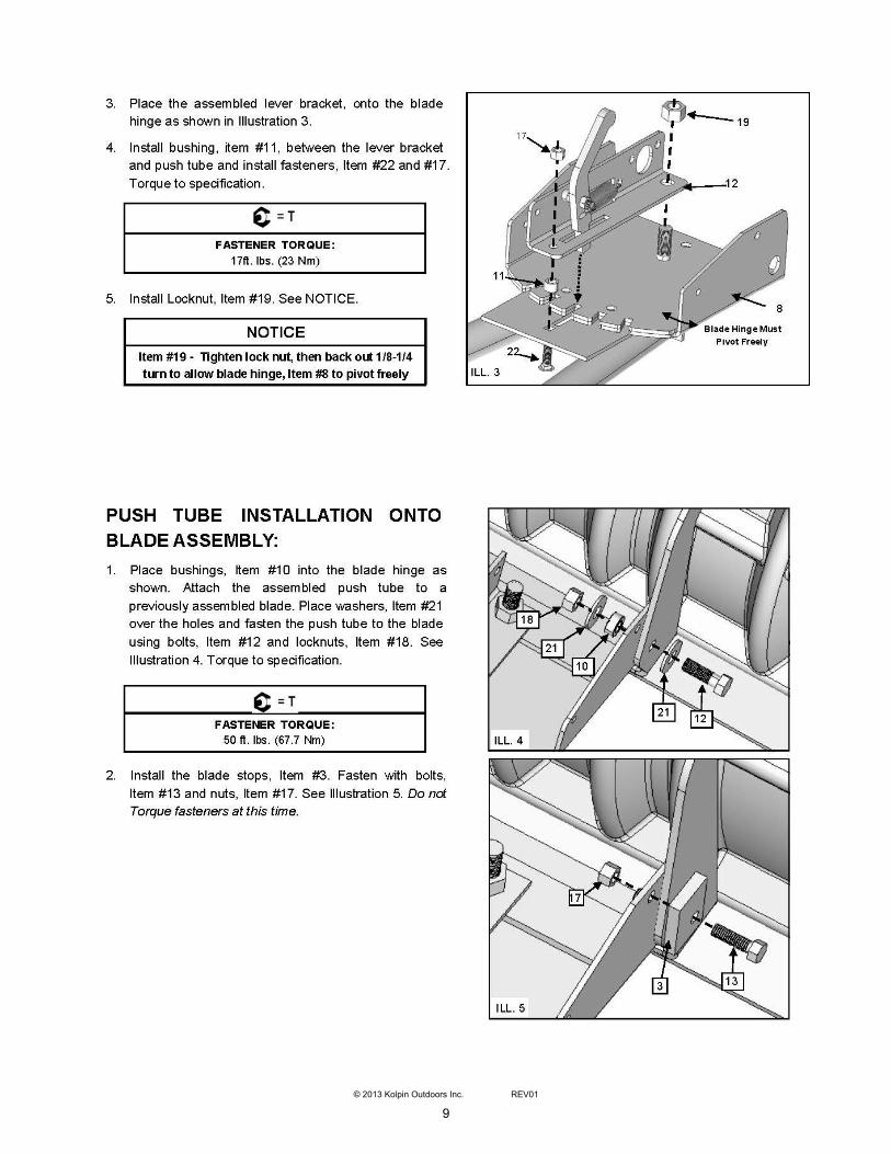
The plow skids are adjustable. General skid setting is even with the plow wear bar bottom edge, higher settings reduce the
chance of rocks and gravel from being collected. See Page 9 for more information.
To increase traction during plow operation, operators can try: Securing weight to the ATV for additional tire downforce, reducing
tire air pressure, or installing tire chains.
SAFETY INFORMATION Our plow systems were designed with your safety in mind. Please read and understand all Cautions, Notices and Warnings in this
manual before you begin. In order to protect you and your ATV, certain parts of the plow system and/or hardware are designed to fail
when the equipment is over-stressed.
WARNING
To avoid personal injury or damage to your vehicle:
Do not install forward mount system over plastic guard
components, which can compress over time and loosen
the installation, resulting in poor product performance
and/or damage to the ATV.
Do not allow forward mount system to interfere with ATV
operational items such as brake lines, coolant hoses,
control cables, steering or any other function.

4
© 2013 Kolpin Outdoors Inc. REV01
PARTS ORDERING INFORMATION:
Replacement fasteners are common-type and can be purchased
locally. Use minimum Metric 8.8 or SAE Grade 5 fasteners.
Model Number 10-0550
Hardware Pack # 12-0400
Parts List 1 of 3

5
© 2013 Kolpin Outdoors Inc. REV01
PARTS ORDERING INFORMATION:
Replacement fasteners are common-type and can be purchased locally. Use
minimum Metric 8.8 or SAE Grade 5 fasteners.
Model Number 10-0550
Hardware Pack # CYC1010
Parts List 2 of 3

6
© 2013 Kolpin Outdoors Inc. REV01
PARTS ORDERING INFORMATION:
Replacement fasteners are common-type and can be purchased
locally. Use minimum metric 8.8 or SAE Grade 5 fasteners.
Model Number 10-0550
Hardware Pack # HK-124
Parts List 3 of 3

7
© 2013 Kolpin Outdoors Inc. REV01
8
© 2013 Kolpin Outdoors Inc. REV01
9
© 2013 Kolpin Outdoors Inc. REV01

10
© 2013 Kolpin Outdoors Inc. REV01

11
© 2013 Kolpin Outdoors Inc. REV01

12
© 2013 Kolpin Outdoors Inc. REV01

13
© 2013 Kolpin Outdoors Inc. REV01
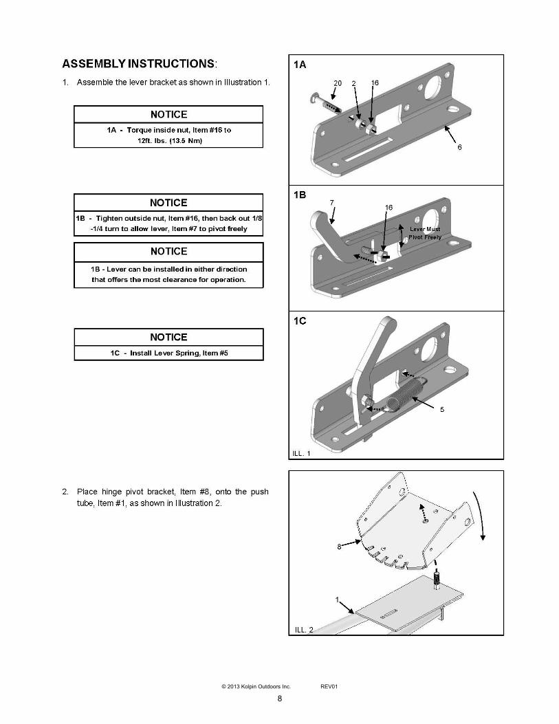
BEFORE YOU BEGIN:
Please read and understand all instructions.
Verify all parts and tools are accounted for.
To ensure a satisfactory installation, follow all stepscorrectly and in the sequence described.
All directions referring to right and left are when therider is sitting on the machine
INSTALLATION NOTES:
TOOLS REQUIRED:
Basic Hand Wrench and Socket Set
Torque Wrench
Plastic Cutting Tool
NOTICE
Position fasteners of the Forward Mount against the
frame as closely as possible - See Illustration
ATV FRONT
Position mount fasteners as shown to create a wedge clamp
force at the frame ‘Y’
INCORRECT
NOTICE
Depending on application, some trimming of plastic guards
or panels may be required to install the Forward Mount.
NOTICE
Refer to Installation Option A, B, C or D for Forward Mount
installation, depending on your application.

14
© 2013 Kolpin Outdoors Inc. REV01
OPTION A - GENERIC MOUNT INSTALLATION FOR ROUND TUBE FRAME ATVs
1. Position the Back Plate, Item #2, on top of the Forward Mount Weldment, Item #1, as shown in Illustration 1.
2. Position the forward mount weldment and back plate under the frame tubes at the “Y” location as shown in Illustration 1.
3. Fasten the mount and back plate using U-bolts, washers and locknuts, Items #4, #5 and #6. Do not torque fasteners at this time.
4. Position the mount and fasteners at a point on the frame that allows the push tube to be attached, but will not interfere with
operation of the ATV.
5. Once the mount position has been determined, position U-bolts to the frame tube walls as close as possible and torque to
specification.
NOTICE
Depending on application, some trimming
of plastic guards or panels may be required.
FASTENER TORQUE:
30 ft. lbs. (41 Nm)
ILL. 1
4
5
6
1
2
GENERIC ROUND TUBE FRAME SECTION
ATV FRONT
14

15
© 2013 Kolpin Outdoors Inc. REV01
OPTION B - GENERIC MOUNT INSTALLATION FOR SQUARE TUBE FRAME ATVs
1. Position the Forward Mount Weldment, Item #1, under the frame tubes at the “Y” location as shown in illustration 2..
2. Position the Back Plate, Item #2, on top of the frame tubes at the “Y” location as shown in Illustration 2.
3. Place spacers, Item #7, between the mount and back plate. Loosely fasten the mount and back plate using bolts, washers and
locknuts, Items #9, #6 and #7. Do not torque fasteners at this time.
4. Position the mount and fasteners at a point on the frame that allows the push tube to be attached, but will not interfere with
operation of the ATV.
5. Once the mount position has been determined, push the spacers and fasteners to the frame tube walls as close as possible.
Torque to specification. REFER TO INSTALLATION NOTES - PAGE 13.
FASTENER TORQUE:
30 ft. lbs. (41 Nm)
NOTICE
Depending on application, some trimming
of plastic guards or panels may be required.
ILL. 2
ATV FRONT
1
2
5
6
7
5
3
15

16
© 2013 Kolpin Outdoors Inc. REV01
OPTION C - MOUNT INSTALLATION: POLARIS 400/500/800 H.O. ATVs
1. Position the Forward Mount Weldment, Item #1, under the frame tubes at the “Y” location as shown in Illustration 1.
2. IMPORTANT: To keep the mount level and clear the built-in rock guard extrusion on Sportsman HO ATVs, add spacers, Item #3 to
the forward channel of the mount. Loosely fasten the spacers between the mount and rock guard with bolts, washers and locknuts,
Items #9, #6 and #7. Do not torque fasteners at this time. See Illustration 3.
3. Position the Back Plate, Item #2, on top of the frame tubes at the “Y” location as shown in Illustration 3.
4. Place spacers, Item #3, between the mount and back plate. Loosely fasten the mount and back plate using bolts, washers and
locknuts, Items #9, #6 and #7. Do not torque fasteners at this time.
5. Once the mount has been positioned, orientate fasteners, to the frame tube walls as close as possible and torque to specification.
REFER TO INSTALLATION NOTES - PAGE 13.
FASTENER TORQUE:
30 ft. lbs. (41 Nm)
ILL. 3 ATV FRONT
ROCK GUARD
2
POLARIS H.O. FRAME SECTION
1
9
4
7
6
3
7
6
8 6
16

STEP 5 - ATTACH PLOW SYSTEM TO
THE FORWARD MOUNT:
1. Refer to Operating Instructions, Page 2 & 3.
2. Once the plow system is attached to your ATV and
the plow blade is on the ground, adjust the blade
stops and blade spring tension as desired to achieve
best performance. Refer to page 10 illustration 7 & 8.
3. Once the desired blade position is obtained, torque
the blade stop fasteners to specification.
FASTENER TORQUE:
17ft. lbs. (23 Nm)
Looking for ATV accessories & parts? Rely on Kolpin for quality and long-lasting products.