komite nasional keselamatan transportasi republic … · enhancing aviation safety. consequently,...
TRANSCRIPT

FINAL KNKT.15.11.26.04
Aircraft Serious Incident Investigation Report
PT. Batik Air Indonesia
Boeing 737-900 ER; PK-LBO
Adisutjipto International Airport
Yogyakarta, Republic of Indonesia
6 November 2015
KOMITE NASIONAL KESELAMATAN TRANSPORTASI REPUBLIC OF INDONESIA
2016

This Final report was produced by the Komite Nasional Keselamatan
Transportasi (KNKT), Transportation Building, 3rd
Floor, Jalan Medan
Merdeka Timur No. 5 Jakarta 10110, Indonesia.
The report is based upon the investigation carried out by the KNKT in
accordance with Annex 13 to the Convention on International Civil
Aviation Organization, the Indonesian Aviation Act (UU No. 1/2009) and
Government Regulation (PP No. 62/2013).
Readers are advised that the KNKT investigates for the sole purpose of
enhancing aviation safety. Consequently, the KNKT reports are confined to
matters of safety significance and may be misleading if used for any other
purpose.
As the KNKT believes that safety information is of greatest value if it is
passed on for the use of others, readers are encouraged to copy or reprint
for further distribution, acknowledging the KNKT as the source.
When the KNKT makes recommendations as a result of its
investigations or research, safety is its primary consideration.
However, the KNKT fully recognizes that the implementation of
recommendations arising from its investigations will in some cases
incur a cost to the industry.
Readers should note that the information in KNKT reports and
recommendations is provided to promote aviation safety. In no case is
it intended to imply blame or liability.

i
TABLE OF CONTENTS
TABLE OF CONTENTS ........................................................................................................ i
TABLE OF FIGURES .......................................................................................................... iv
ABBREVIATIONS AND DEFINITIONS ........................................................................... v
INTRODUCTION .............................................................................................................. viii
1 FACTUAL INFORMATION ......................................................................................... 1
1.1 History of the Flight............................................................................................... 1
1.2 Injuries to Persons.................................................................................................. 3
1.3 Damage to Aircraft ................................................................................................ 3
1.4 Other Damage ........................................................................................................ 3
1.5 Personnel Information ........................................................................................... 3
1.5.1 Pilot in Command ..................................................................................... 3
1.5.2 Second in Command ................................................................................ 4
1.5.3 Flight Attendant ........................................................................................ 5
1.6 Aircraft Information............................................................................................... 5
1.6.1 General ..................................................................................................... 5
1.6.2 Engines ..................................................................................................... 5
1.6.3 Weight and Balance .................................................................................. 6
1.6.4 Runway Awareness and Advisory System ............................................... 6
1.7 Meteorological Information ................................................................................... 7
1.8 Aids to Navigation ................................................................................................. 8
1.8.1 The ILS Approach Profile ........................................................................ 9
1.9 Communications .................................................................................................. 10
1.10 Aerodrome Information ....................................................................................... 10
1.11 Flight Recorders................................................................................................... 12
1.11.1 Flight Data Recorder .............................................................................. 12
1.11.2 Cockpit Voice Recorder ......................................................................... 13
1.11.3 Significant Events from Recorders ......................................................... 14
1.12 Wreckage and Impact Information ...................................................................... 15
1.13 Medical and Pathological Information ................................................................ 16
1.14 Fire ....................................................................................................................... 16
1.15 Survival Aspects .................................................................................................. 17
1.16 Tests and Research .............................................................................................. 18

ii
1.17 Organizational and Management Information ..................................................... 19
1.17.1 Aircraft Operator .................................................................................... 19
1.17.1.1 Operation Manual ................................................................. 19
1.17.1.2 Company Airport Briefing .................................................... 25
1.17.1.3 Safety Emergency Procedure ................................................ 25
1.17.1.4 Flight Attendant Manual ....................................................... 29
1.17.1.5 Special Airport Information .................................................. 31
1.17.1.6 Boeing 737-800/900ER Flight Crew Operations Manual .... 32
1.17.1.7 Boeing 737 Quick Reference Handbook .............................. 33
1.17.1.8 Boeing 737 NG Flight Crew Training Manual ..................... 33
1.17.1.9 Boeing 737-600/700/800/900 Aircraft Maintenance
Manual .................................................................................. 37
1.17.2 Airport Operator ..................................................................................... 38
1.17.2.1 Aerodrome Manual ............................................................... 38
1.17.2.2 SOP – Runway, Taxiway and Apron Inspection .................. 41
1.17.2.3 SOP – Runway Friction Test ................................................ 43
1.17.3 Air Traffic Services Provider ................................................................. 45
1.17.4 Directorate General of Civil Aviation .................................................... 45
1.17.4.1 Civil Aviation Safety Regulation Part 139 – Volume I
Aerodrome ............................................................................ 45
1.17.4.2 Manual of Standard (MOS) CASR Part 139 – Volume I
Aerodrome ............................................................................ 46
1.17.4.3 Advisory Circular CASR Part 139-23 .................................. 50
1.17.4.4 Staff Instruction 139-01 ........................................................ 53
1.17.4.5 Advisory Circular 170-02 ..................................................... 54
1.18 Additional Information ........................................................................................ 55
1.18.1 Reporting of Runway Surface Condition ............................................... 55
1.19 Useful or Effective Investigation Techniques ..................................................... 58
2 ANALYSIS ..................................................................................................................... 59
2.1 Decision to land ................................................................................................... 59
2.2 Factors Affecting Landing Distance .................................................................... 60
2.3 Landing Distances ............................................................................................... 61
2.4 Braking Action Assessment ................................................................................. 64
2.5 Passenger Evacuation .......................................................................................... 65

iii
3 CONCLUSION .............................................................................................................. 66
3.1 Findings ............................................................................................................... 66
3.2 Contributing Factors ............................................................................................ 68
3.3 Other Safety Issue ................................................................................................ 68
4 SAFETY ACTION ........................................................................................................ 69
5 SAFETY RECOMMENDATIONS ............................................................................. 72
5.1 PT. Batik Air Indonesia ....................................................................................... 72
5.2 PT. Angkasa Pura Airport Branch Adisutjipto International Airport .................. 72
5.3 AirNav Indonesia District Office Yogyakarta ..................................................... 72
5.4 Directorate General of Civil Aviation ................................................................. 73
6 APPENDICES................................................................................................................ 74
6.1 Notice to Pilot ...................................................................................................... 74
6.2 Company NOTAM .............................................................................................. 77
6.3 Safety Notice ....................................................................................................... 78
6.4 Safety Plan of Runway End Safety Area Runway 27.......................................... 82
6.5 Direct Involve Parties Comments .......................................................................... 3
6.5.1 National Transportation Safety Board ...................................................... 3
6.5.2 Directorate General of Civil Aviation ...................................................... 9

iv
TABLE OF FIGURES
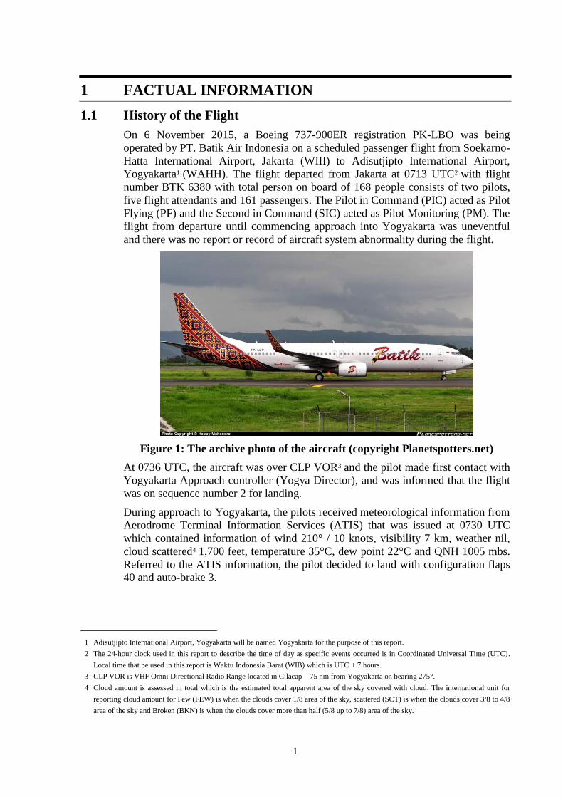
Figure 1: The archive photo of the aircraft (copyright Planetspotters.net) ......................................... 1
Figure 2: The aircraft condition just after stopped .............................................................................. 2
Figure 3: The aircraft after the impact with the nose wheel folded backward .................................... 3
Figure 4: Satellite image at 0820 UTC provided by BMKG .............................................................. 8
Figure 5: The ILS approach chart published in AIP Volume II .......................................................... 9
Figure 6: The last rubber deposit cleaning location .......................................................................... 10
Figure 7: The airport layout published on Aeronautical Information Publication ............................ 11
Figure 8: The airport layout published by Jeppesen .......................................................................... 11
Figure 9: The significant FDR parameters ........................................................................................ 12
Figure 10: The aircraft movement based on FDR data ..................................................................... 15
Figure 11: The main and nose wheel marks (indicated by arrows) ................................................... 15
Figure 12: Nose wheel mark on the grass (left) and the Aircraft last position after passenger evacuated
(right) ................................................................................................................................. 16
Figure 13: Auto brake selection at ―MAX‖....................................................................................... 16
Figure 14: Flight attendant position .................................................................................................. 17
Figure 15: The friction test scheme ................................................................................................... 44

v
ABBREVIATIONS AND DEFINITIONS
AC : Advisory Circular
ADC : Aerodrome Control Tower
AFE : Above Field Elevation
AIP : Aeronautical Information Publication
AM : Aerodrome Manual
AOC : Airline Operator Certificate
APP : Approach Control Unit
ARFF : Airport Rescue and Fire Fighting
ATC : Air Traffic Control
ATIS : Automatic Terminal Information Service
ATPL : Airline Transport Pilot License
ATS : Air Traffic Service
AWOS : Automatic Weather Observation Sytem
BMKG : Badan Meteorologi Klimatologi Geofisika
°C : Centigrade
CAB : Company Airport Briefing
CASR : Civil Aviation Safety Regulation
CCTV : Close Circuit Television
CET : Crew Emergency Training
COM : Company Operation Manual
CPL : Commercial Pilot License
CRM : Crew Resource Management
CVR : Cockpit Voice Recorder
DGCA : Directorate General of Civil Aviation
EGPWS : Enhanced Ground Proximity Warning System
FA : Flight Attendant
FAM : Flight Attendant Manual
FCOM : Flight Crew Operation Manual
FCTM : Flight Crew Training Manual
FDR : Flight Data Recorder
FIR : Flight Information Region
FOD : Foreign Object Damaged

vi
FPPM : Flight Planning and Performance Manual
ft : Feet
ICAO : International Civil Aviation Organisation
ILS : Instrument Landing System
IMC : Instrument Meteorological Condition
KNKT : Komite Nasional Keselamatan Transportasi
kts : Knots
LPPNPI / AirNav : Lembaga Penyelenggara Pelayanan Navigasi Penerbangan Indonesia
LT : Local Time
m : Meter
MAC LDG : Mean Aerodynamic Chord Landing
MAC TOW : Mean Aerodynamic Chord Take-off weight
MHz : Megahertz
MLW : Maximum Landing Weight
MTOW : Maximum Take-off Weight
NNC : Non Normal Checklist
NOTAM : Notice to Airmen
NTP : Notice to Pilot
OAT : Outside Air Temperature
OM : Operation Manual
PAPI : Precision Approach Path Indicator
PF : Pilot Flying
PIC : Pilot in Command
PKP-PK : Pertolongan Kecelakaan Penerbangan dan Pemadam Kebakaran (see
ARFF)
PM : Pilot Monitoring
PMS : Pavement Management System
QFE : Altimeter setting based on aerodrome elevation air pressure
QNH : Altimeter setting based on mean sea level air pressure
RAAS : Runway Awareness Advisory System
RESA : Runway End Safety Area
SAI : Special Airport Information
SEP : Safety Emergency Procedure
SI : Staff Instruction

vii
SIC : Second in Command
SMS : Safety Management System
SOP : Standard Operation Procedure
TALPA ARC : Take-off and Landing Performance Assessment Aviation Rules
Committee
UTC : Universal Coordinated Time
VHF : Very High Frequency
VMC : Visual Meteorological Condition
VOR : Very High Frequency Omni-directional Range

viii
INTRODUCTION
SYNOPSIS
On 6 November 2015, a Boeing 737-900ER registration PK-LBO was being operated by PT.
Batik Air Indonesia on a scheduled passenger flight from Soekarno-Hatta International
Airport, Jakarta (WIII) to Adisutjipto International Airport, Yogyakarta (WAHH) with flight
number BTK 6380. The flight departed from Jakarta at 0713 UTC with total person on board
of 168 people and the Pilot in Command (PIC) acted as Pilot Flying (PF) while the Second in
Command (SIC) acted as Pilot Monitoring (PM). The flight from departure until commencing
approach into Yogyakarta was uneventful and there was no report or record of aircraft system
abnormality during the flight.
After received meteorological information from Aerodrome Terminal Information Services
(ATIS) the pilot decided to land with configuration flaps 40 and auto-brake 3. While
approaching Yogyakarta, the pilots noticed cumulonimbus cloud over Yogyakarta then
decided to follow wind shear precaution recommendation to use flaps 30 for landing.
During Instrument Landing System (ILS) approach runway 09, the pilot received information
that the runway was wet and decided to change the selection of the auto-brake from three to
maximum.
The FDR data indicated that at altitude 10 feet the speed was 159 knots and floated for 6
seconds then touched down at 730 meters from beginning runway 09 on speed 154 knots. The
aircraft stopped at about 84 meters from end of runway 09 and passenger evacuation initiated
9 minutes after. No one injured in this accident.
Four conditions affecting the landing distance, specifically the aircraft floated for about 6
seconds and touched down at 427 meter beyond the aim point, after bouncing once; the
airspeed at touchdown was 13 knots above Vref, and there was average tailwind of 6 knots;
the thrust reversers were stowed at a higher than recommended speed and there was little
braking for about 305 meter after the autobrakes were disconnected; and the wet runway
conditions resulted in less deceleration.
The investigation concluded the contributing factors to this accident are:
The absence of landing distance calculation following landing reconfiguration and the
higher speed with no reminder callout might have made the pilots decided to continue
landing, and
The conditions of the aircraft floated and eventually touched down at the end of the
touchdown zone 13 knots above Vref with average 6 knots tailwind, lower brake pressure
for 305 meter after the autobrakes were disconnected, and removal of the thrust reverser
application at a higher than recommended speed along with medium braking action had
extended the landing distance.
The investigation also considered the external factors such as runway condition might have
contributed to the reducing of deceleration rate while the brake pressure and thrust reversers
were close to maximum.
Following this accident PT. Batik Air Indonesia has issued 24 safety actions which considered
relevant to improve safety. In addition, KNKT issued safety recommendations addressed to
PT. Batik Air Indonesia, PT. Angkasa Pura Airport branch Adisutjipto International Airport,
AirNav Indonesia district office Yogyakarta and the Directorate General of Civil Aviation.
1
1 FACTUAL INFORMATION
1.1 History of the Flight
On 6 November 2015, a Boeing 737-900ER registration PK-LBO was being
operated by PT. Batik Air Indonesia on a scheduled passenger flight from Soekarno-
Hatta International Airport, Jakarta (WIII) to Adisutjipto International Airport,
Yogyakarta1 (WAHH). The flight departed from Jakarta at 0713 UTC2 with flight
number BTK 6380 with total person on board of 168 people consists of two pilots,
five flight attendants and 161 passengers. The Pilot in Command (PIC) acted as Pilot
Flying (PF) and the Second in Command (SIC) acted as Pilot Monitoring (PM). The
flight from departure until commencing approach into Yogyakarta was uneventful
and there was no report or record of aircraft system abnormality during the flight.
Figure 1: The archive photo of the aircraft (copyright Planetspotters.net)
At 0736 UTC, the aircraft was over CLP VOR3 and the pilot made first contact with
Yogyakarta Approach controller (Yogya Director), and was informed that the flight
was on sequence number 2 for landing.
During approach to Yogyakarta, the pilots received meteorological information from
Aerodrome Terminal Information Services (ATIS) that was issued at 0730 UTC
which contained information of wind 210° / 10 knots, visibility 7 km, weather nil,
cloud scattered4 1,700 feet, temperature 35°C, dew point 22°C and QNH 1005 mbs.
Referred to the ATIS information, the pilot decided to land with configuration flaps
40 and auto-brake 3.
1 Adisutjipto International Airport, Yogyakarta will be named Yogyakarta for the purpose of this report.
2 The 24-hour clock used in this report to describe the time of day as specific events occurred is in Coordinated Universal Time (UTC).
Local time that be used in this report is Waktu Indonesia Barat (WIB) which is UTC + 7 hours.
3 CLP VOR is VHF Omni Directional Radio Range located in Cilacap – 75 nm from Yogyakarta on bearing 275°.
4 Cloud amount is assessed in total which is the estimated total apparent area of the sky covered with cloud. The international unit for
reporting cloud amount for Few (FEW) is when the clouds cover 1/8 area of the sky, scattered (SCT) is when the clouds cover 3/8 to 4/8
area of the sky and Broken (BKN) is when the clouds cover more than half (5/8 up to 7/8) area of the sky.
2
While approaching Yogyakarta, the pilots noticed cumulonimbus cloud over
Yogyakarta as indicated by magenta figure on the weather radar and decided to
follow windshear 5 precaution recommendation as described on the Flight Crew
Operations Manual (FCOM) to use flaps 30 for landing6.
At 0754 UTC, the aircraft established on the localizer runway 09 and the flight was
transferred to Adisutjipto Tower controller (Adi Tower).
At 0756 UTC, the pilot asked the Adi Tower whether the runway was wet and it was
affirmed by Adi Tower. Referring to the runway condition, the pilots decided to
change the selection of the auto-brake to maximum.
At 0758 UTC, the Adi Tower had visual contact with the aircraft and asked the pilot
whether runway was insight, and was confirmed by the pilot. Adi Tower issued
landing clearance followed by additional information of wind condition was calm
and runway was wet.
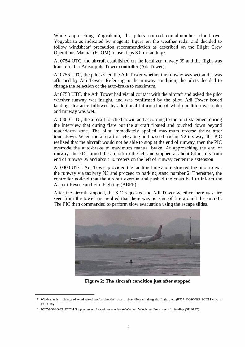
At 0800 UTC, the aircraft touched down, and according to the pilot statement during
the interview that during flare out the aircraft floated and touched down beyond
touchdown zone. The pilot immediately applied maximum reverse thrust after
touchdown. When the aircraft decelerating and passed abeam N2 taxiway, the PIC
realized that the aircraft would not be able to stop at the end of runway, then the PIC
overrode the auto-brake to maximum manual brake. At approaching the end of
runway, the PIC turned the aircraft to the left and stopped at about 84 meters from
end of runway 09 and about 80 meters on the left of runway centerline extension.
At 0800 UTC, Adi Tower provided the landing time and instructed the pilot to exit
the runway via taxiway N3 and proceed to parking stand number 2. Thereafter, the
controller noticed that the aircraft overrun and pushed the crash bell to inform the
Airport Rescue and Fire Fighting (ARFF).
After the aircraft stopped, the SIC requested the Adi Tower whether there was fire
seen from the tower and replied that there was no sign of fire around the aircraft.
The PIC then commanded to perform slow evacuation using the escape slides.
Figure 2: The aircraft condition just after stopped
5 Windshear is a change of wind speed and/or direction over a short distance along the flight path (B737-800/900ER FCOM chapter
SP.16.26).
6 B737-800/900ER FCOM Supplementary Procedures – Adverse Weather, Windshear Precautions for landing (SP.16.27).

3
1.2 Injuries to Persons
There was no injury to person as a result of this occurrence and all occupants were
Indonesian.
1.3 Damage to Aircraft
The aircraft damaged on its belly. The observation found that the lock pin of the
nose gear that provides structural support for the nose gear broken into three pieces
and caused the nose wheel folded backward then damaged the forward belly.
Figure 3: The aircraft after the impact with the nose wheel folded backward
1.4 Other Damage
There was no other damage to property and/or the environment.
1.5 Personnel Information
1.5.1 Pilot in Command
Gender : Male
Age : 45 years
Nationality : Indonesian
Marital status : Married
Date of joining company : 25 March 2009
License : ATPL
Date of issue : 10 August 2014
Validity : 30 April 2016
Aircraft type rating : MD-80; MD-90; B737-NG
Instrument rating validity : 31 October 2016
Medical certificate : First Class
Last of medical : 31 July 2015
Validity : 31 March 2016
Medical limitation : The holder shall possess glasses that correct
for near vision.
4
Last line check : 7 March 2015
Last proficiency check : 23 November 2015
Flying experience
Total hours : 3,628 hours 26 minutes
Total on type : 2,661 hours 40 minutes
Last 90 days : 85 hours 36 minutes
Last 60 days : 42 hours 36 minutes
Last 24 hours : 4 hours 6 minutes
This flight : 58 minutes
Last emergency training : May 2015
1.5.2 Second in Command
Gender : Male
Age : 22 years
Nationality : Indonesian
Marital status : Single
Date of joining company : 3 November 2013
License : CPL
Date of issue : 10 June 2013
Validity : 30 April 2016
Aircraft type rating : B737-NG
Instrument rating validity : 30 April 2016
Medical certificate : First Class
Last of medical : 5 November 2015
Validity : 31 May 2016
Medical limitation : None
Last line check : Not applicable
Last proficiency check : 1 May 2015
Flying experience
Total hours : 1,787 hours 55 minutes
Total on type : 1,596 hours 50 minutes
Last 90 days : 246 hours 18 minutes
Last 60 days : 179 hours 46 minutes

5
Last 24 hours : 4 hours 6 minutes
This flight : 58 minutes
Last emergency training : October 2015
1.5.3 Flight Attendant
All flight attendants on this flight held valid licenses and medical certificate.
1.6 Aircraft Information
1.6.1 General
Registration : PK-LBO
Manufacturer : Boeing Aircraft Company
Country of Manufacturer : United States of America
Type/ Model : 737-9GPER
Serial Number : 38731
Year of manufacture : 2013
Certificate of Airworthiness
Issued : 28 May 2015
Validity : 27 May 2016
Category : Transport
Limitations : None
Certificate of Registration
Registration Number : 3306
Issued : 28 May 2015
Validity : 27 May 2016
Time Since New : 9,185 hours 7 minutes
Cycles Since New : 4,691 cycles
Last Major Check : Nil
Last Minor Check : 14 August 2015 (P09)
1.6.2 Engines
Manufacturer : CFM International
Type/Model : Turbo Fan / CFM56-7B26E
Serial Number-1 engine : 963832
Time Since New : 7,693 hours 12 minutes
Cycles Since New : 3,915 cycles
Serial Number-2 engine : 962841

6
Time Since New : 9,185 hours 7 minutes
Cycles Since New : 4,691 cycles
1.6.3 Weight and Balance
The aircraft departed Jakarta for Yogyakarta within the proper weight and balance
envelope, as shown in the following table:
Maximum Take-off weight : 78,017 kg
Actual take-off weight : 66,110 kg
Maximum landing weight : 71,350 kg
Estimated landing weight : 63,910 kg
MAC TOW : 25.03 %
MAC TOW Limit : 13.1 – 30.3 %
MAC LDG : 25.55 %
According to Operator Flight Crew Operations Manual (FCOM) Chapter PI.20.5, for
configuration of flap 30 at landing weight of 65,000 kg, the Vref was 142 knots and
at landing weight 60,000 kg, the Vref was 136 knots. Based on these data, the
interpolation for landing weight 63,910 kg, Vref landing with configuration of flap
30 was 141 knots.
1.6.4 Runway Awareness and Advisory System
The aircraft equipped with Honeywell SmartRunway®/SmartLanding® as a
Runway Awareness and Advisory System (RAAS) which provides information
associated with landing configuration and or profiles. One of the features is
providing aural warning about distance remaining during landing role. Several
descriptions of the RAAS features taken from Honeywell Product Description -
SmartRunway®/SmartLanding® are as follows:
4.2.4 Distance Remaining – Landing Roll-Out Advisory
The purpose of the Distance Remaining advisories is to enhance crew awareness of
aircraft along-track position relative to the runway end.
4.2.4.1 Annunciation Criteria
The Distance Remaining advisory is generated when the following conditions are
met: Aircraft is within 100 feet of the ground, over the last half of the runway or a
specified distance from the runway end; or Aircraft is on the ground, on the last half
of the runway (default) or a specified distance from the runway end, and Aircraft
ground speed is above 40 knots.
7
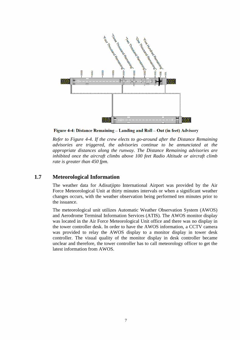
Refer to Figure 4-4. If the crew elects to go-around after the Distance Remaining
advisories are triggered, the advisories continue to be annunciated at the
appropriate distances along the runway. The Distance Remaining advisories are
inhibited once the aircraft climbs above 100 feet Radio Altitude or aircraft climb
rate is greater than 450 fpm.
1.7 Meteorological Information
The weather data for Adisutjipto International Airport was provided by the Air
Force Meteorological Unit at thirty minutes intervals or when a significant weather
changes occurs, with the weather observation being performed ten minutes prior to
the issuance.
The meteorological unit utilizes Automatic Weather Observation System (AWOS)
and Aerodrome Terminal Information Services (ATIS). The AWOS monitor display
was located in the Air Force Meteorological Unit office and there was no display in
the tower controller desk. In order to have the AWOS information, a CCTV camera
was provided to relay the AWOS display to a monitor display in tower desk
controller. The visual quality of the monitor display in desk controller became
unclear and therefore, the tower controller has to call meteorology officer to get the
latest information from AWOS.

8
The weather reported by Yogyakarta ATIS on 6 November 2015 was as follows:
0730 UTC 0734 UTC 0800 UTC 0830 UTC
Wind 200° / 10 knots 220° / 6 knots 300° / 3 knots 240° / 2 knots
Visibility 7 km 7 km 3 km 3 km
Weather NIL NIL Slight Rain Slight Rain
Cloud Scatter 1,700 ft Scatter 1,700 ft Scatter 1,700 ft Scatter 1,700 ft
Temp. /
Dew point 35° C / 22° C 35° C / 22° C 32° C / 23° C 32° C / 23° C
QNH 1,005 mbar /
70 inHg
1,009 mbar /
29.80 inHg
1,006 mbar /
29.71 inHg
1,006 mbar /
29.71 inHg
QFE 993 mbar /
233 inHg
993 mbar /
29.33 inHg
993 mbar /
29.34 inHg
994 mbar /
29.35 inHg
Remarks No significant Rain in North
Area No significant No significant
The satellite weather image provided by Badan Meteorologi Klimatologi dan
Geofisika (BMKG – Bureau of Meteorology, Climatology and Geophysics) at 0820
UTC, which was about 20 minutes after the occurrence, showed the clouds
formation on the west of the Yogyakarta.
Figure 4: Satellite image at 0820 UTC provided by BMKG
1.8 Aids to Navigation
Runway 09 Yogyakarta was equipped with an Instrument Landing System (ILS)
approach guidance facilities, operating on frequency 109.1 MHz. The last calibration
was performed on 31 October 2015 and the next periodic calibration should be
performed on 30 April 2016. On the day of the accident, the ILS was serviceable and
functioning properly.
9
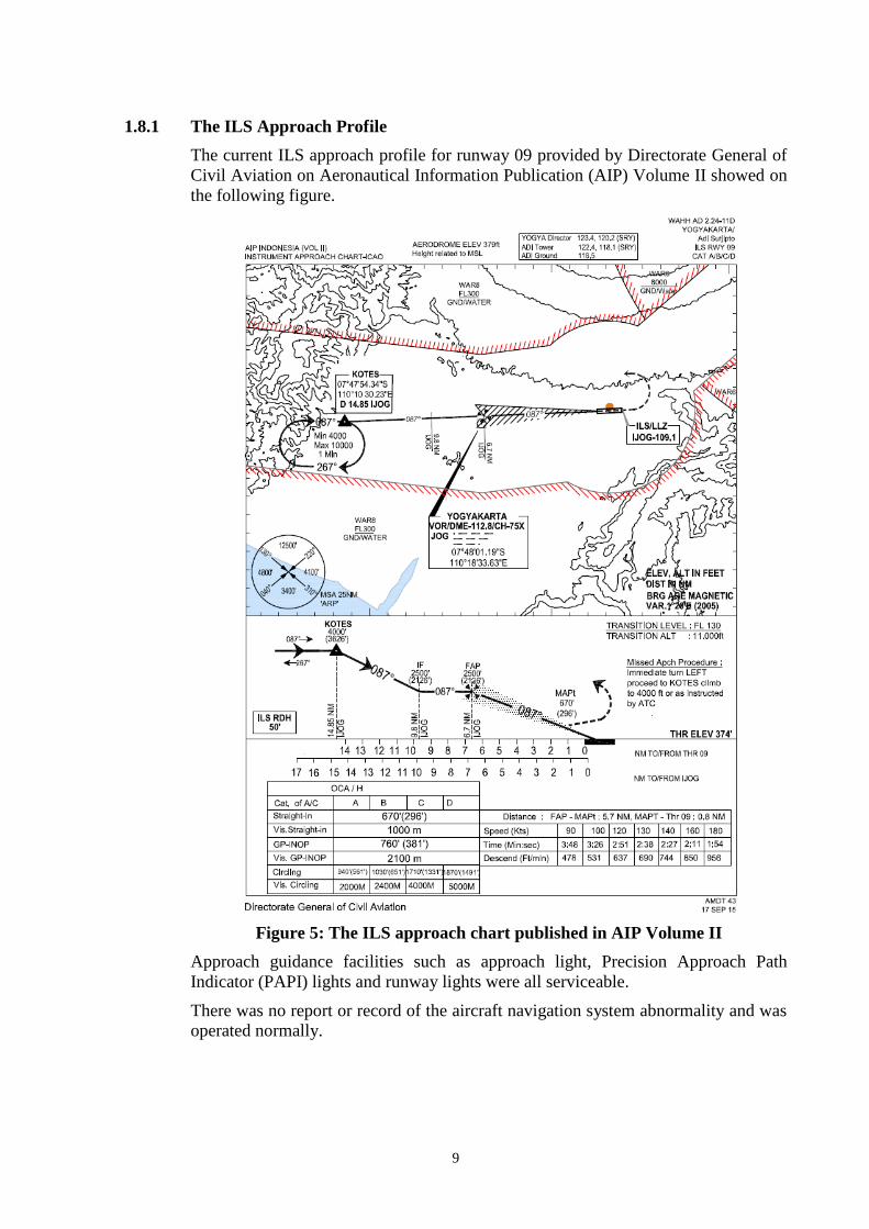
1.8.1 The ILS Approach Profile
The current ILS approach profile for runway 09 provided by Directorate General of
Civil Aviation on Aeronautical Information Publication (AIP) Volume II showed on
the following figure.
Figure 5: The ILS approach chart published in AIP Volume II
Approach guidance facilities such as approach light, Precision Approach Path
Indicator (PAPI) lights and runway lights were all serviceable.
There was no report or record of the aircraft navigation system abnormality and was
operated normally.

10
1.9 Communications
All communications between Air Traffic Services (ATS) and the crew were normal
as recorded on ground based automatic voice recording equipment and Cockpit
Voice Recorder (CVR) for the duration of the flight. The quality of the recorded
transmissions was good.
1.10 Aerodrome Information
Airport Name : Adisutjipto International Airport
Airport Identification : WAHH / JOG
Airport Operator : PT. Angkasa Pura Airport (Persero)
Airport Certificate : 018/SBU-DBU/XI/2015
Validity : 30 July 2020
Coordinate : 07°47’12‖S 110°25’55‖E
Elevation : 350 feet
Runway Direction : 09 – 27 / 087° – 267°
Runway Dimension : 2,200 x 45 meters
Runway Strip Dimension : 2,285 x 300 meters
Runway End Safety Area
Runway 09 : 90 x 90 meters
Runway 27 : Not available with exemption
Surface : Asphalt
Fire fighting category : VII
Remarks : The airport was military airbase, and on
1975 the function was changed to enclave
civil and military airport that served military
training flight, domestic and international
passenger flight.
The last rubber deposit cleaning was performed on 29 October 2015 by using
chemical liquid (Magnus 758) on touchdown runway 09 area of 1,500 m2 (figure 6).
Figure 6: The last rubber deposit cleaning location

11
Figure 7: The airport layout published on Aeronautical Information
Publication
Figure 8: The airport layout published by Jeppesen
There was different information related to stopway, clearway and RESA between
Aerodrome Information Publication (AIP) and Jeppesen publication.

12
1.11 Flight Recorders
1.11.1 Flight Data Recorder
The aircraft was fitted with Honeywell HFR5-D Flight Data Recorder (FDR) model
with part number 980-4750-009 and serial number 02242. The recorder was
transported to KNKT recorder facility for data downloading process. The FDR
recorded 1,265 parameters and approximately 53 hours of aircraft operation, which
was containing 31 flights including the accident flight.
Figure 9: The significant FDR parameters
The red boxes on figure 9 showed significant event that will be described on chapter
1.11.3 (Recorders Significant Events).

13
1.11.2 Cockpit Voice Recorder
The aircraft was fitted with Honeywell CVR 120 model with part number 980-6022-
001 and serial number 15719. The recorder was transported to KNKT recorder
facility for data downloading process. The CVR recorded 2 hours and 1 minute of
good quality recording data. The significant excerpts from the CVR are as follows:
Note:
EGPWS is Enhanced Ground Proximity Warning System
P1 is PIC
P2 is SIC
TWR is Adisutjipto Tower controller
RAAS is Runway Awareness and Advisory System
Time (UTC) From Communication
8:00:10.567 EGPWS Ten
8:00:16.000 Touchdown (from FDR data)
8:00:16.239 P2 Speed brake up
8:00:16.813 RAAS Four Thousand Remaining
8:00:19.560 P2 Reverser normal
8:00:24.263 RAAS Two Thousand Remaining
8:00:28.157 P1 Auto brake disarm
8:00:28.552 P2 Auto brake disarm
8:00:31.220 RAAS One Thousand Remaining
8:00:33.572 TWR Provided landing time and instructed to taxi via
November 3 to parking stand number 2
8:00:34.046 P2 Brake
8:00:35.291 RAAS Five Hundred Remaining
8:00:37.900 Noisy sound heard
8:00:51.458 P2 Speed brake
8:00:53.000 The aircraft stopped (from FDR data)
8:00:55.015 P2 Attention, attention crew on station
8:00:55.015 P1 Brace brace brace
8:00:57.426 P2 Capt , shutdown capt
8:01:07.110 P1 Brace brace brace
8:01:21.617 Chime

14
1.11.3 Significant Events from Recorders
The significant events recorded from 07:59:23 UTC at altitude 676 feet (all altitude
on this sub chapter is based on radio height) until the aircraft stopped at 08:00:53
UTC were as follows:
07:59:23 UTC, Auto pilot and auto throttle disconnected at approximately 700
feet.
At 500 feet, the speed brake was armed.
The N1s value at 07:59:43 UTC, at altitude 381 feet was 60% and the speed
was 157 knots, and at 08:00:06 UTC, at altitude 87 feet increased to 70%
followed by speed increasing from 153 knots up to 159 knots at 10 feet.
07:59:52 UTC, at 229 feet the PM advised the PF to fly right and
acknowledged by PF.
From approximately 200 feet to 10 feet, the average tail wind was 6 knots.
08:00:07 UTC, the aircraft passed altitude 50 feet with speed of 153 knots.
08:00:10 UTC, the altitude was 10 feet at speed of 159 knots and touch down 6
seconds later. The average speed from altitude 10 feet to touchdown was 156
knots.
08:00:16 UTC, the aircraft touched down with the speed of 154 knots (Vref +
13), bounced briefly and touched down a second time followed by RAAS aural
―Four Thousand Remaining‖.
08:00:18 UTC, the thrust reversers were deployed, followed by all spoiler
deployment and auto-brake activation with the average brake pressure of
approximately 2,494 psi and N1 84.8%. The average of longitudinal
acceleration was -0.27 G for 8 seconds.
08:00:24 UTC, RAAS aural ―Two Thousand Remaining‖.
08:00:28 UTC, the auto brake disarmed, the average brake pressure dropped to
approximately 785 psi for 3 seconds, until manual braking was applied and the
pressure increased to 3,000 psi again, the longitudinal acceleration increased.
08:00:33 UTC, the reverser stowed for approximately seven seconds at
approximately 76 knots, although they had been reduced from the maximum
setting at 91 knots.
08:00:37 UTC, noisy sound heard, the aircraft heading changed and the
longitudinal acceleration was -0.03 G and then decreased on average -0.31 G.
08:00:45 UTC, the pitch angle changed from -0.88° to -1.41°.
08:00:53 UTC, the aircraft stopped.

15
1.12 Wreckage and Impact Information
After the aircraft leaving the pavement, there were no sign of nose wheel mark on
the gravel instead of an indentation the gravel with the dimension approximately 50
cm in width and 150 cm in length. Subsequently, after the indentation, there was a
long single scrath mark on the gravel until the aircraft final position.
The aircraft stopped at about 80 meters on the left of runway 09 centerline extension
and about 84 meters from end of runway 09 with the nose landing gear collapsed.
Figure 10: The aircraft movement based on FDR data
Figure 11: The main and nose wheel marks (indicated by arrows)

16
The first impact on the soft surface, with the
dimension of approximately 50 cm in width and
150 cm in length
Figure 12: Nose wheel mark on the grass (left) and the Aircraft last position after
passenger evacuated (right)
Figure 13: Auto brake selection at “MAX”
1.13 Medical and Pathological Information
No medical or pathological investigations were conducted as a result of this
occurrence, nor were they required.
1.14 Fire
There was no evidence of fire in-flight or after the aircraft impacted terrain.

17
1.15 Survival Aspects
08:00:53 UTC, two seconds after the aircraft stopped, the SIC commanded
―ATTENTION CREW ON STATION‖ and the PIC commanded ―BRACE,
BRACE, BRACE‖.
08:01:07 UTC, the PIC made another command ―BRACE, BRACE, BRACE‖.
08:01:09 UTC, the SIC asked PIC to set the engine power to idle.
08:01:21 UTC, the pilot called flight attendant using chime and commanded the
Flight Attendant 1 (FA-1) to check the possibility of fire and standby for further
instruction through interphone.
The FA-1 and FA-4 positions were in forward area and the FA-2, FA-3 and FA-5
were in aft area.
Figure 14: Flight attendant position
08:01:33 UTC, the crew started the APU.
After noticed the aircraft overrun, the Adi Tower controller (Adi Tower) pressed
crash bell and informed the Airport Rescue and Fire Fighting (ARFF) that the
aircraft had overrun. According to the airport CCTV, the ARFF arrived at accident
site in approximately two and half minutes after the aircraft stopped. According to
ARFF observation there was no sign of pre or post impact fire.
08:02:26 UTC, the SIC requested to Adi Tower for monitoring the possibility of fire
and was replied that there was no sign of fire on the aircraft.
08:02:37 UTC, the FA commanded the passengers to stay on their seats.
08:03:08 UTC, the crew called the FA-1 by using chime and informed that the APU
generator was available.
08:03:21 UTC, the crew turned on the air conditioning from the APU bleed-air.
08:03:49 UTC, the PIC asked SIC to read evacuation checklist.
08:04:03 UTC, the pilots started the evacuation checklist.
08:04:09 UTC, Adi Tower asked for the total person on board the aircraft.
08:04:59 UTC, the pilots finished the evacuation checklist.
08:05:02 UTC, the SIC informed the PIC that the ARFF provided a stair and asked
to the PIC whether will use escape slide or stair. The PIC answered to use stair
instead of escape slide.
18
08:05:11 UTC, the PIC invited the FA-1 into the cockpit and commanded to disarm
the slide bar and to tell the passenger on emergency row not to open the emergency
exit windows as the PIC seen ARFF personnel climbed to the left wing used stair.
The FA-1 then informed to FA-4 to disarm the slide bar and then to pass the
command to flight attendants on aft by using megaphone as the interphone system
did not work.
08:06:12 UTC, the SIC asked the PIC to make announcement to calm down the
passengers.
08:07:19 UTC, the FA-1 informed the pilot through interphone that the Public
Address (PA) was not working, and the PIC commanded to arm the slide bar in
order to expedite the evacuation. The FA-4 informed the PIC’s command to arm the
slide bar to flight attendants on the aft by using megaphone and was received by FA-
5.
08:09:07 UTC, the SIC informed Adi Tower that the evacuation would use the
escape slides. The escape slide on right forward passenger door was inflated by FA-
4. The FA-2 and FA-3 armed and inflated the escape slide on the aft doors (3R and
4R) after received instruction from FA-5. The FA-1 was unable to open the left
forward passenger (1L) door fully after several attempts. When the door was
partially opened, the ARFF personnel approached carried a stair. The FA-1 then
disarmed the slide bar and opened the 1L door. The passenger disembarked through
1L door used the stair.
08:09:14 UTC, the passenger evacuation initiated.
08:10:37 UTC, the crew discussed the equipment should be take by SIC during the
evacuation.
08:11:11 UTC, the SIC asked the PIC of the fire extinguisher location.
08:11:36 UTC, the SIC informed the PIC that he would leave the cockpit.
08:13:24 UTC, the Adi Tower asked the pilot whether any injury to person and
replied that most likely there was no injury.
08:16:59 UTC, the FA-1 came to cockpit and informed the PIC that all passengers
have been completely evacuated.
08:18:52 UTC, the PIC informed Adi Tower that he was leaving the aircraft.
1.16 Tests and Research
There is no test or research was required to be conducted as a result of this
occurrence.

19
1.17 Organizational and Management Information
1.17.1 Aircraft Operator
PT. Batik Air Indonesia (Batik Air) as an aircraft operator held valid Air Operator
Certificate (AOC) number 121-050 that operated total of 33 fleets consisted of 13
Airbus A320, 14 Boeing 737-800 and 6 Boeing 737-900ER, which served 27
destinations and operated up to 160 flights daily.
The Batik Air had several manuals that were approved by Directorate General of
Civil Aviation. The following are the relevant excerpts taken from operator manuals
as reference for the investigation.
1.17.1.1 Operation Manual
Since 1 April 2015, PT. Batik Air changed the format of their Company Operation
Manual (COM) to become Operation Manual (OM) that consisted into four parts.
The description of each part is as follows:
OM Part A described general policies, rules, standards and procedures defining
the manner of company operations are conducted.
OM Part B described the aircraft operation information such as limitation,
performance, normal, abnormal and emergency procedure.
OM Part C described the necessary route and airport specific information with
respect to company area of operation.
OM Part D described information and instructions to all flight crew, flight
attendants, flight operation officers, instructors and checkers, with procedures,
instructions and information relative to the training of those personnel for the
respective positions and aircraft type in which they are to serve.
OM Part A
CHAPTER 5 - QUALIFICATIONS REQUIREMENTS
5.1.5.2 CREWMEMBERS SAFETY AND EMERGENCY TRAINING
In addition to type-specific emergency training provided to flight crew member in
the respective aircraft type qualification curriculum segments (emergency and
abnormal procedures associated with aircraft systems, structural design,
operational characteristics, etc.), all crewmembers receive ―general‖ Safety and
Emergency Training., addressing:
Instructions in emergency assignments and procedures, including
coordination among crewmembers;
Individual instruction in the location, function and operation of emergency
equipment;
Instruction in the handling of emergency situation;
Review and discussion of previous aircraft accidents and incidents pertaining
to actual emergency situation.

20
Two distinct areas of training are required in the conduct of the ―general‖
emergency training:
―Emergency drills‖ training;
―Emergency evacuation‖ training (also referred to as ―emergency
evacuation (wet)‖ training).
Both training areas are therefore addressed as part of each BATIK AIR initial
training curriculum for crewmember. These personnel then receive subsequent
training in these areas as part of their respective recurrent training (every year).
CHAPTER 8 – OPERATING PROCEDURES
8.1.4.5 LANDING LIMITATIONS
8.1.4.5.1 DEFINITIONS
CONTAMINATED RUNWAY - A runway is contaminated when more than 25 per
cent of the runway surface area (whether in isolated areas or not) within the
required length and width being used is covered by:
Water, or slush more than 3 mm (0.125 in) deep;
Loose snow more than 20 mm (0.75 in) deep; or
Compacted snow or ice, including wet ice.
DRY RUNWAY - A dry runway is one which is clear of contaminants and visible
moisture within the required length and the width being used.
WET RUNWAY - A runway that is neither dry nor contaminated.
8.1.4.5.3 AERODROME OF DESTINATION – WET AND CONTAMINATED
RUNWAYS
When landing on WET or CONTAMINATED runway is anticipated, the LDA must
be at least 115% of the required landing distance for landing on a DRY runway.
In a few words:
8.3.2.9 LANDING
8.3.2.9.1 SAFE LANDING GUIDELINES
The risk of approach and landing accident is increased if one of the following is not
met. If more than one guideline is not met, the overall risk is increased:
Fly a stabilized approach;
Height at threshold crossing is 50 ft.;
Speed at threshold crossing is not more than VREF +10 kts and not less than
VREF;
Tailwind is not more than 10 knots on non-contaminated runway and not more
than 0 knots on contaminated runway;
Touchdown on runway centerline on touchdown aim point;
After touchdown promptly transition to the desired configuration:
Required Landing Distance (WET or CONTA) = 115% Required Landing Distance (DRY) ≤ LDA

21
Brakes;
Spoiler/speed brakes;
Thrust reverser (once thrust reverse is activated, go around is no longer
an option);
Speed is not more than 80 knots with 2000 ft. runway remaining.
8.3.2.9.2 ACTUAL LANDING DISTANCE
Contrary to the dispatch phase, the actual execution of a landing is not governed by
regulatory Required Landing Distance as detailed in OM Part A, Chapter 8.1.4.5
―Landing limitations‖.
The only requirement is that the landing must be conducted in a safe manner and the
aircraft can be brought to a full stop within the Landing Distance Available (LDA).
The actual landing distance information in the FCOM/QRH is provided to guide the
PIC in his assessment of the possibly critical nature of a particular landing. It
should be realized that the figures in the FCOM/QRH are based on stated reference
conditions. If these reference conditions cannot be exactly duplicated, the accuracy
of the given figures is invalidated.
The decision to land basically remains with the PIC, who must take the following
into account:
The actual landing distance figure, corrected as applicable must carefully be
weighed for its realism under the prevailing operating conditions. If
considered necessary, the landing distance must be increased arbitrarily;
If the (increased) landing distance plus any margin specified in the
FCOM/QRH is not available, a landing is not permitted.
The margin is intended to cover minor imperfections in flight handling and
judgment. If deviations occur, the pilot must not hesitate in executing go-
around.
8.3.2.9.3 USE OF THRUST REVERSERS AND/OR BRAKE
The use of reverse thrust as laid down in the FCOM increases the operational safety
margins and considerably increases the brakes and tires life, with no adverse effects
to the engines. Excessive use of wheel brakes to gain an early runway turn-off point
is undesirable, unless urgent operational reasons are involved.
IDLE reverse must be selected immediately after main gear touchdown. MAX
reverse is available and should be used if required. If MAX reverse is used it should
be reduced to IDLE reverse when reaching 60-70 kts in deceleration (depending on
the aircraft, refer to respective aircraft type FCOM for specific value). IDLE reverse
must then be used until reaching taxi speed.
8.3.2.9.4 BOUNCED LANDING / LONG FLARE
If a hard and/or high bounce occurs, a go-around must be initiated.
If landing within the touchdown zone is not ensured and the remaining runway is
insufficient to stop safety, a go-around must be initiated.
22
8.3.20.12 EMERGENCY LANDING ON LAND
8.3.20.12.3 EVACUATION OF THE AIRCRAFT
When the command ―EVACUATE‖ has been given by the PIC or, in the case of
unexpected landings, by the SFA/FA-1, or when the aircraft has come to rest, all
occupants must leave the aircraft as quickly as possible and in an orderly manner.
Crewmembers present in the cabin shall direct the evacuation procedure. In
general, all the available exits shall be used as well as the assisting means as, e.g.
ropes, evacuation chutes etc. All occupants must direct to leave the aircraft and
move far away from it.
No one shall be allowed to re-enter the aircraft until sometime it has become quite
clear, that there is no danger of fire or explosion. Wounded and disabled occupants
shall be assisted by the unhurt, but this must not delay the evacuation process. The
PIC is the last to leave the aircraft after having checked that everyone has escaped.
8.3.20.14 EVACUATION DIRECTIVES
8.3.20.14.1 GENERAL
Most emergency situations develop during the initial or final stage of the flight. It
must be realized that the preparation phase may be varying brief or even non-
existent. Flight crew and Flight attendants should be prepared for expected and
specially unexpected emergencies.
8.3.20.14.4 INITIATION OF THE EVACUATION
When the aircraft comes to a full stop under abnormal conditions the PIC after give
a command ―ATTENTION FLIGHT ATTENDANT ON STATION― twice and
evaluate situation will decide whether evacuation is required or not, and contact the
FA-1. In this case, FA-1 will check the outside conditions and coordinated with
other FA. If there is no command from the PIC, FA-1 will immediately check the
PIC to ensure if evacuation is required.
Criteria for initiating evacuation:
The PIC has the prime responsibility for initiating a passenger evacuation;
If a Flight Attendant consider an evacuation is necessary he must advise the
PIC of the situation and await the PIC decision;
The Flight Attendants may take full responsibility for initiating the evacuation,
in the following cases:
It is obvious an evacuation is imperative;
No contact with the flight crew/PIC has been possible;
The safety of people is in jeopardy such as:
Heavy smoke inside or outside the aircraft;
Fire;
Severe Structural damage.
Another Flight Attendant has started evacuating passengers. If an
evacuation is initiated by a Flight Attendant, inform the Flight Crew
that an evacuation is in progress.

23
In case of evacuation required the PIC command: ―EVACUATE‖ (repeated
command). If evacuation is not required, the PIC should immediately make the
following PA announcement: ―FLIGHT ATTENDANT AND PASSENGER KEEP
YOUR SEAT‖.
After check out side conditions and coordinate with other FA and the condition are
judged safe, FA-1 will make the following Public Address announcement:
Para tamu yang terhormat
Captain sedang mengevaluasi keadaan.
Tetaplah duduk dengan tenang di kursi
masing.
Pengumuman selengkapnya akan kami
berikan secepatnya
Ladies and Gentlemen
Captain is evaluating the situation.
Please keep calm and remain seated.
Further information will be given to you
as soon as possible.
If conditions are judge unsafe, FA-1 will report to the cockpit immediately. The PIC
will command via PA: ―EVACUATE‖. In this case, the PIC and the FA will
immediately execute their own procedures. If conditions are judge safe and the
evacuation is not required, the PIC will immediately make PA announcement:
―FLIGHT ATTENDANTS AND PASSENGERS KEEP YOUR SEAT‖
In this case, FA-1 will make announcement via PA
Para tamu yang terhomat
Keadaan pesawat sudah dapat
dikendalikan.
Anda kami minta agar tetap duduk
dengan tenang.
Ladies and Gentlemen
Everything is under controlled.
Please keep calm and remain seated.
When the aircraft comes to full stop under abnormal condition and the aircraft
conditions are judge unsafe, the PIC will immediately command: ―EVACUATE―. In
this case, the Crewmembers will immediately execute their own procedures.
NOTE: If no PAS available, use megaphone.

24
8.3.20.14.5 EVACUATION COMMANDS FLOWCHART
Safety Directive cards are also available onboard for use by crew. Refer to OM Part
A, Appendix 8.J.
8.3.20.14.6 POST EVACUATION
Evacuation is completed after all passengers and crews have evacuated the aircraft.
Some post evacuation actions should be carried out as standard procedure. Such as:
Lead passenger away (up wind) from the aircraft because of risk of explosion
and fire;
Bring passenger and crew together (after accident, people often start running
away in a shock condition);
Care for the injured;
Coordinate actions to overcome the first few hours (let other people help or
take care each other).

25
OM PART C CHAPTER 2 – PERFORMANCE STUDIES
2.2 RUNWAY ANALYSES
For each airport from/to which it operates with a specific aircraft type, BATIK AIR
conducts specific take-off and landing performance studies (runway analysis),
accounting for each individual runway characteristics, obstacles, and whose
purpose is to provide flight crew with a simplified means to obtain maximum take-off
weight, V-speeds, or landing weights allowing to comply with all limitations as
described in OM Part A, Chapter 8.1.4.3 ―Take-off limitations‖ and Chapter 8.1.4.5
―Landing limitations‖.
For Boeing fleets, these analyses are conducted using up-to-date runway and
obstacle data, the approved Airplane Flight Manual, the type-specific Flight
Planning and Performance Manual (FPPM), and the Boeing performance software
(BPS).
Outcomes of these analyses are published on dedicated charts:
Take-off performance charts provide a means to quickly determine maximum
allowable takeoff weight, takeoff speeds, and assumed temperature for
maximum and derate thrusts, and different aircraft configurations, as well as
engine-out procedures;
Landing performance charts provide a means to quickly determine required
landing distances and threshold speeds using selected braking in different
aircraft configurations.
All charts relative to regular BATIK AIR destinations are made available in a type-
specific Runway Analysis Manual (RAM). For non-scheduled / supplemental
operations to an airport which is not included in the Runway Analysis Manual, the
Flight Operations engineering section will publish ad’hoc charts that will be
included in a customized trip kit.
1.17.1.2 Company Airport Briefing
Company Airport Briefing (CAB) is a new version of Special Airport Information
that contains detailed information about several airports in Indonesia. The special
limitation of Adisutjipto airport that described on CAB was as follows:
B. SPECIAL LIMITATIONS
MAX Tailwind and Crosswind limits: As per SOP Limitation.
1.17.1.3 Safety Emergency Procedure
1.1. Company regulations
1.1.1. Crew Briefing
The Crew Member pre-flight safety briefing consists of a join briefing involving all
Flight Crews and Flight Attendants. It must be accomplished prior to the first flight
of each day and include a coordinated Flight Crew or procedural review of one
area of safety. This briefing is mandatory for all operations with Flight Attendant.

26
Flight Attendant briefings are given by the Captain or Purser/FA-1 prior to or just
after boarding the aircraft. The Captain has opportunity to discuss procedures,
preferably emergency procedures that must be performed without delay.
The Purser/FA-1 checks FA knowledge of emergency items. In cases of aircraft
change or change of part of the crew on trip, the Purser/FA-1 is responsible for type
specific briefing of new or all Flight Attendants.
If however, the Captain considers a complete briefing necessary, the Purser/FA-1
must be informed.
Briefings may include, but is not limited to:
a. Crew introductions
b. Ensuring that each Flight Attendant has up-to-date Flight Attendant Manual,
ID card, certificate and passport. A periodic check of the F.A.M. of each Flight
Attendant should be conducted to ensure the F.A.M is kept up to date by
individual Flight Attendant.
c. Flight information from the trip advisory such as destination, estimated
passenger loads, passengers counting method, lengths of flights, approved
service and work assignments, rules of destination country and any other
specific passenger requirements
d. Recent company information
e. A discussion initiated by the PIC, of at lease one area of safety such as
Evacuation, rapid depressurization and emergency descent, fire, etc
f. An emergency procedure review, such as commands from the Flight crew and
actions to be taken by Flight Attendants, operation of the doors, location and
operation of the emergency equipment, bomb threat and hijack.
g. Stowage of crew and passengers baggage consistent with company policy h.
Standards issues such as appearance, attitude and behavior.
2.2. Procedures to check and to operate
Each required crewmember shall before beginning a flight, familiarize his/her self
with the emergency equipment installed on each aircraft to which he/she is assigned
and with the procedures to be followed for the use of that equipment in an
emergency situation.
3. EMERGENCY PROCEDURES
3.1. Evacuation Procedures
3.1.1. Warning Signal
During evacuation, it must be expected that only emergency exit lights are available.
If an emergency requires an immediate evacuation it shall be performed according
to the ―Warning Signal‖ irrelevant if it is a prepared or unprepared evacuation.
The order to evacuate is principally given by the Pilot in Command. All emergency
commands from Flight crew including possible limitations shall be given twice.
a. The Primary signal is: ―FLIGHT ATTENDANT INTO COCKPIT‖ and the
Secondary signal is: ―At least 6(six) chimes‖ Only Purser/FA-1 in-charge may
come to the Flight deck

27
b. ―EMERGENCY STATION‖
This signal will be given Approximately 2(two) minutes or equal with 1000 feet
before impact. (If the Public address unserviceable, command will be given
when the Purser/FA-1 report ―CABIN READY‖).
c. ―BRACE‖
This command will be given:
i. Approximately 1(one) minute or equal with 500 feet before impact.
ii. During Takeoff and Landing when the Pilot in Command decided an
emergency situation (If time permit)
(If PA unserviceable, command will be given by flashing the Fasten seat belt
sign)
d. ―ATTENTION CREW ON STATION‖
Except ditching, this command should be given:
i. In all emergencies situations
ii. When the aircraft stop under abnormal conditions (During Takeoff and
Landing)
It shall alert the Flight Attendant to await further commands from the Flight
crew. Because of the Flight crew activities, there may be a relative long time
between stand still of the aircraft and further commands. This shall not lead to
hasty actions by the Flight Attendants. During this alert phase, Flight
Attendants should unfasten seatbelt (if fasten), get up, check door mode, reflect
on emergency door operation, take the most suitable position for evacuation at
the assigned exit.
The situation (inside) and outside the cabin shall be observed very carefully.
e. ―FLIGHT ATTENDANT AND PASSENGERS KEEP YOUR SEAT‖
This command should be given incase an evacuation is not required.
A further announcement by the Flight crew will follow (e.g. we return to the
ramp).
f. ―EVACUATE‖
This command should be given for an immediate evacuation.
Incase of unusable exits, Flight Attendants should divert passengers to usable
exits:
i. Face the passengers
ii. Block exit, explain with emphasis that exit is unusable: ―EXIT
BLOCKED‖ or ―FIRE OUT SIDE‖ or ―NO SLIDE HERE‖
GO TO THAT EXIT (while pointing to the usable exits and keeps guarding
the unusable exit until evacuation is completed.
g. ―EVACUATE - KEEP CLOSE…..‖ (e.g. 1R/1L)
This restrict command should be given when the Pilot in Command cannot
declare all exits free for the evacuation.
Note: If one or more exits on one side are mentioned, they shall principally
remain close. However, each Flight Attendant eventually has to decide after
careful check of actual conditions (inside) and outside the cabin whether an

28
exit is usable.
h. ―CONTROLLED DISEMBARKATION‖
There are cases, where passengers should leave the aircraft as a precautionary
measure (e.g.: bomb scares, smoke in the cabin) without the urgency of an
emergency evacuation. In those cases the Captain may decide on a
―CONTROLLED DISEMBARKATION‖
The passengers shall be informed if hand luggage may be taken from board. If
stairs cannot be provided in an acceptable period of time, one or more slides
shall be used.
Since there is no time critical urgency in a ―CONTROLLED
DISEMBARKATION‖, it is not considered necessary to have a pre formulated
announcement. The Captain gives an appropriate explanation to passengers
and mentions the doors that shall be used.
In a ―CONTROLLED DISEMBARKATION‖ via slides, the passengers should
be ordered to:
i) Leave hand luggage on board
ii) Take-off high heel shoes
iii) Sit down and slide
3.1.5. Criteria for initiating evacuation
The Captain has the prime responsibility for initiating a passenger evacuation.
If a Flight Attendant consider an evacuation is necessary he/she must advise the
Captain of the situation and await the Captain’s decision.
The Flight Attendants may take full responsibility for initiating the evacuation in
cases:
a. WHERE IT IS OBVIOUS AN EVACUATION IS IMPERATIVE
b. NO CONTACT WITH THE FLIGHT CREW/CAPTAIN HAS BEEN
POSSSIBLE
c. THE SAFETY OF PEOPLE IS IN JEOPARDY such as:
i. Heavy smoke inside or outside the aircraft
ii. Fire
iii. Severe structural damage
d. Another Flight Attendant has started evacuating passengers. (if an
evacuating is initiated by a Flight Attendant, refer to point c inform the Flight
crew that an evacuation is in progress)
Note: Never evacuate a moving aircraft, or while the engines are still running.
As doing so can result in serious injury to passengers and damage to the evacuation
devices.

29
1.17.1.4 Flight Attendant Manual
4.3.3. Warning signals
4.3.3.1 Flight crew to Flight Attendants
Flight Attendants must be aware of all signals that warn of an emergency or
potential emergency.
―All (emergency) commands from the Flight crew will be given twice‖
a. The Primary signal is: ―FLIGHT ATTENDANT INTO COCKPIT‖ and the
Secondary signal is: ―At least 6(six) chimes‖
Only Purser/FA-1 in-charge may come to the Flight deck
b. ―EMERGENCY STATION‖
This signal will be given Approximately 2(two) minutes or equal with 1000 feet
before impact. (If the Public address unserviceable, command will be given
when the Purser/FA-1 report ―CABIN READY‖).
c. ―BRACE‖
This command will be given:
ii. Approximately 1(one) minute or equal with 500 feet before impact.
iii. During Takeoff and Landing when the Pilot in Command decided an
emergency situation (If time permit)
(If PA unserviceable, command will be given by flashing the Fasten seatbelt
sign)
d. ―ATTENTION CREW ON STATION‖
Except ditching, this command should be given:
i. In all emergencies situations
ii. When the aircraft stop under abnormal conditions (During Takeoff and
Landing)
It shall alert the Flight Attendant to await further commands from the Flight
crew. Because of the Flight crew activities, there may be a relative long time
between stand still of the aircraft and further commands. This shall not lead to
hasty actions by the Flight Attendants. During this alert phase, Flight
Attendants should unfasten seatbelt (if fasten), get up, check door mode, reflect
on emergency door operation, take the most suitable position for evacuation at
the assigned exit.
The situation inside and outside the cabin shall be observed very carefully.
e. ―FLIGHT ATTENDANT AND PASSENGERS KEEP YOUR SEAT‖
This command should be given incase an evacuation is not required.
A further announcement by the Flight crew will follow (e.g. we return to the
ramp).
f. ―EVACUATE‖
This command should be given for an immediate evacuation.
Incase of unusable exits, Flight Attendants should divert passengers to usable
exits:
i. Face the passengers
ii. Block exit, explain with emphasis that exit is unusable:

30
―EXIT BLOCKED‖ or ―FIRE OUT SIDE‖ or ―NO SLIDE HERE‖
GO TO THAT EXIT (while pointing to the usable exits and keeps guarding the
unusable exit until evacuation is completed.
g. ―EVACUATE - KEEP CLOSE……‖ (e.g. R/1L)
This restrict command should be given when the Pilot in Command cannot
declare all exits free for the evacuation.
Note: If one or more exits on one side are mentioned, they shall principally
remain close. However, each Flight Attendant eventually has to decide
after careful check of actual conditions (inside) and outside the cabin
whether an exit is usable.
h. ―CONTROLLED DISEMBARKATION‖
There are cases, where passengers should leave the aircraft as a precautionary
measure (e.g.: bomb scares, smoke in the cabin) without the urgency of an
emergency evacuation. In those cases the Captain may decide on a
―CONTROLLED DISEMBARKATION‖
The passengers shall be informed if hand luggage may be taken from board. If
stairs can not be provided in an acceptable period of time, one or more slides
shall be used.
Since there is no time critical urgency in a ―CONTROLLED
DISEMBARKATION‖, it is not considered necessary to have a pre formulated
announcement. The Captain gives an appropriate explanation to passengers
and mentions the doors that shall be used.
In a ―CONTROLLED DISEMBARKATION‖ via slides, the passengers should
be ordered to:
i) Leave hand luggage on board
ii) Take-off high heel shoes
iii) Sit down and slide
4.3.14. Principles of Evacuation
a. Each evacuation should be initiated as quickly as possible after the aircraft has
completely stopped, using all possibility at hand to get passengers without
hand luggage in a safe distance from the aircraft.
b. Passengers and crew shall evacuate an aircraft if they are endangered due to
the condition of the aircraft.
c. Skidding off the runway during landing, without visual damage to the aircraft
does not require an immediate evacuation.
d. Every evacuation is a risky procedure and should therefore be performed only
when absolutely necessary.
e. Always be alert to the possibility of passengers initiating an unpremeditated or
undirected emergency evacuation.
f. A passenger initiated emergency evacuation could, if not quickly controlled,
lead to widespread panic and the possibility of serious to fatal injury to those
drawn into such unpremeditated evacuation.
g. Immediately upon becoming aware that an unpremeditated emergency
evacuation is beginning, shout loudly and clearly, "KEEP CALM, REMAIN

31
SEATED" or "STOP, RETURN TO YOUR SEATS, REMAIN CALM". Wait for
Captain command and then take any steps necessary (including physical
restraint) to prevent passengers from opening doors or removing exits. Enlist
the help of other passengers if possible. If no command from the cockpit refer
to 4.3.19 (secondary action point IV).
1.17.1.5 Special Airport Information
Special Airport Information (SAI) is a manual that published 25 October 2013 and
contains detailed information about several airports in Indonesia in order to enhance
pilots familiarity with the region and to address specific requirements like transition
altitude, altimetry changes, very high en-route altitudes, political unrest or other
non-operational informal that would provide additional guidance to crew operating
within or to that area.
This manual was replaced with Company Airport Briefing (CAB) since April 2015.
However, the pilots were still using the SAI at the day of accident as a guideline for
landing in Yogyakarta.
According Batik Air Special Information book, Adisutjipto International Airport
(Yogyakarta) was classified as Category B airport, which was required a written
Airport Brief disseminated to crew for proper study and understanding to ensure safe
level of operations.
Category B airports require extra consideration such as:
a) Non-standard approach aids and/or approach patterns; or
b) Unusual local weather conditions; or
c) Unusual characteristics or performance limitations; or
d) Any other relevant considerations including obstructions, physical layout,
lighting, etc.
Yogyakarta was associated with peculiarities of traffic congested, military training
area and special corridor for departure and arrival.
The special limitation of Adisutjipto airport that described on SAI was as follows:
3.18. YOGYAKARTA – WARJ (JOG)
b) SPECIAL LIMITATIONS
1. No take off or landing in heavy rain, when the RWY is contaminated.
2. Dry RWY : MAX Tailwind 10 knots MAX Crosswind 20 knots
3. Wet RWY : MAX Tailwind 5 knots. ( PIC as PF ) MAX Crosswind 15 knots
Use MAX auto brakes during wet runway operations.
4. MTOW : 70,300 KGS for dry or wet RWY
5. MLW : 70,300 KGS for dry or wet RWY

32
1.17.1.6 Boeing 737-800/900ER Flight Crew Operations Manual
Normal Configuration Landing Distance
The following is the information of normal configuration landing distance on page
PI.22.2 for good and medium braking action on flaps 30.
Good braking action means the value is comparative and intended to mean that
aircraft should not experience braking or directional control difficulties when
landing.
The landing distance is calculated from a reference distance of 50 feet above the
threshold to stop for the particular landing weight and normal approach speed for the
selected landing flap at sea level, zero wind, zero slope, and two engine detent
reverse thrust.
Copyright © Boeing. Reprinted with permission of The Boeing Company.
33
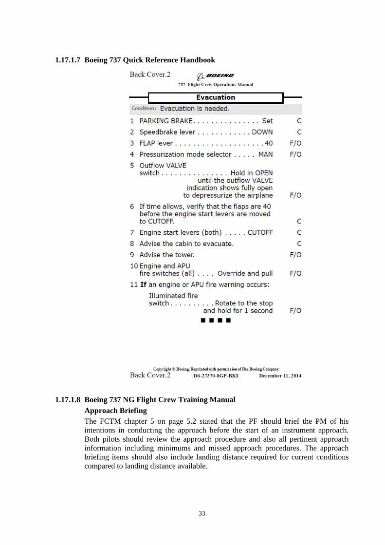
1.17.1.7 Boeing 737 Quick Reference Handbook
1.17.1.8 Boeing 737 NG Flight Crew Training Manual
Approach Briefing
The FCTM chapter 5 on page 5.2 stated that the PF should brief the PM of his
intentions in conducting the approach before the start of an instrument approach.
Both pilots should review the approach procedure and also all pertinent approach
information including minimums and missed approach procedures. The approach
briefing items should also include landing distance required for current conditions
compared to landing distance available.
34
Recommended Elements of a Stabilized Approach (5.5)
The following recommendations are consistent with criteria developed by the Flight
Safety Foundation.
All approaches should be stabilized by 1,000 feet AFE in instrument
meteorological conditions (IMC) and by 500 feet AFE in visual meteorological
conditions (VMC). An approach is considered stabilized when all of the following
criteria are met:
the airplane is on the correct flight path
only small changes in heading and pitch are required to maintain the correct
flight path
the airplane should be at approach speed. Deviations of +10 knots to – 5
knots are acceptable if the airspeed is trending toward approach speed
the airplane is in the correct landing configuration
sink rate is no greater than 1,000 fpm; if an approach requires a sink rate
greater than 1,000 fpm, a special briefing should be conducted
thrust setting is appropriate for the airplane configuration
all briefings and checklists have been conducted.
Specific types of approaches are stabilized if they also fulfill the following:
ILS and GLS approaches should be flown within one dot of the glide slope
and localizer, or within the expanded localizer scale
approaches using IAN should be flown within one dot of the glide path and
FAC
during a circling approach, wings should be level on final when the airplane
reaches 300 feet AFE.
Unique approach procedures or abnormal conditions requiring a deviation from the
above elements of a stabilized approach require a special briefing.
Note: An approach that becomes unstabilized below 1,000 feet AFE in IMC or
below 500 feet AFE in VMC requires an immediate go-around.
These conditions should be maintained throughout the rest of the approach for it to
be considered a stabilized approach. If the above criteria cannot be established and
maintained until approaching the flare, initiate a go-around.
At 100 feet HAT for all visual approaches, the airplane should be positioned so the
flight deck is within, and tracking to remain within, the lateral confines of the
runway edges extended.
Chapter 6 – Landing
Factors Affecting Landing Distance (6.32)
Factors that affect stopping distance include: height and speed over the threshold,
glide slope angle, landing flare, lowering the nose to the runway, use of reverse
thrust, speedbrakes, wheel brakes and surface conditions of the runway.

35
Note: Reverse thrust and speedbrake drag are most effective during the high
speed portion of the landing. Deploy the speedbrake lever and activate
reverse thrust with as little time delay as possible.
Note: Speedbrakes fully deployed, in conjunction with maximum reverse thrust
and maximum manual antiskid braking provides the minimum stopping
distance.
Floating above the runway before touchdown must be avoided because it uses a
large portion of the available runway. The airplane should be landed as near the
normal touchdown point as possible. Deceleration rate on the runway is
approximately three times greater than in the air.
Transition to Manual Braking (6.37)
The speed at which the transition from autobrakes to manual braking is made
depends on airplane deceleration rate, runway conditions and stopping
requirements. Normally the speedbrakes remain deployed until taxi speed, but may
be stowed earlier if stopping distance within the remaining runway is assured.
When transitioning to manual braking, use reverse thrust as required until taxi
speed. The use of speedbrakes and reverse thrust is especially important when
nearing the end of the runway where rubber deposits affect stopping ability.
Manual Braking (6.37)
For short or slippery runways, use full brake pedal pressure.
do not attempt to modulate, pump or improve the braking by any other special
techniques
do not release the brake pedal pressure until the airplane speed has been
reduced to a safe taxi speed
If the pilot modulates the brake pedals, the antiskid system is forced to readjust the
brake pressure to establish optimum braking. During this readjustment time,
braking efficiency is lost.
Copyright © Boeing. Reprinted with permission of The Boeing Company.

36
Reverse Thrust Operation
The FCTM chapter 6 on page 6.40, pilot shall maintain the reverse thrust as
required, up to maximum until the airspeed approached 60 knots.
Runway Condition Assessment – TALPA ARC (6.40)
The following table is an abbreviated version of the Matrix for runway condition
assessment in terms of Takeoff and Landing Performance Assessment Aviation Rules
Committee (TALPA ARC) categories. The runway condition descriptions and codes
are aligned with control/braking action reports.
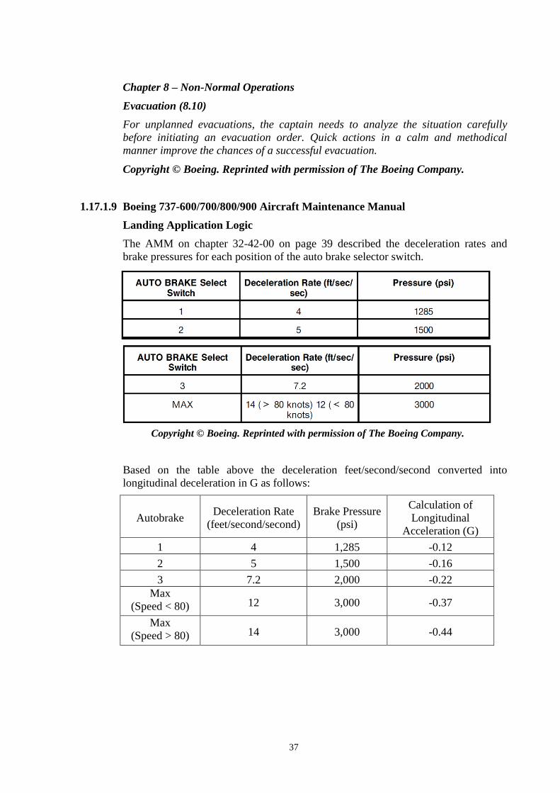
37
Chapter 8 – Non-Normal Operations
Evacuation (8.10)
For unplanned evacuations, the captain needs to analyze the situation carefully
before initiating an evacuation order. Quick actions in a calm and methodical
manner improve the chances of a successful evacuation.
Copyright © Boeing. Reprinted with permission of The Boeing Company.
1.17.1.9 Boeing 737-600/700/800/900 Aircraft Maintenance Manual
Landing Application Logic
The AMM on chapter 32-42-00 on page 39 described the deceleration rates and
brake pressures for each position of the auto brake selector switch.
Copyright © Boeing. Reprinted with permission of The Boeing Company.
Based on the table above the deceleration feet/second/second converted into
longitudinal deceleration in G as follows:
Autobrake Deceleration Rate
(feet/second/second)
Brake Pressure
(psi)
Calculation of
Longitudinal
Acceleration (G)
1 4 1,285 -0.12
2 5 1,500 -0.16
3 7.2 2,000 -0.22
Max
(Speed < 80) 12 3,000 -0.37
Max
(Speed > 80) 14 3,000 -0.44

38
1.17.2 Airport Operator
The Adisutjipto International Airport was military airbase and since 1975 the
function was changed to enclave civil and military operation. The airport was
operated by PT. Angkasa Pura Airport, a state owned enterprise that operated 13
airports in Indonesia.
The PT. Angkasa Pura Airport branch Adisutjipto International Airport has a Safety
Management System (SMS) unit led by manager with outsourcing staffs that
responsible to the implementation of SMS. The observation found that there were no
activities related to the hazard identification, risk assessment and mitigation
concerning to the runway surface condition and the friction.
The PT. Angkasa Pura Airport branch Adisutjipto International Airport has an
Aerodrome Manual (AM) as general guidelines in the airport operation.
Furthermore, the detail guidelines were described on Standard Operating Procedures
(SOPs). The AM and SOPs are presented only in Bahasa Indonesia and translated to
English on this investigation report.
The relevant issue taken from the airport operator AM and SOPs related to the
runway operation and maintenance issues, particularly on topics of runway
inspection, standing water, runway friction and rubber deposit.
1.17.2.1 Aerodrome Manual
Bab 4 Prosedur Pengoperasian Bandar
Udara
Chapter 4 Airport Operational
Procedure
4.5 Pemeriksaan/Inspeksi Daerah
Pergerakan dan Obstacle Limitation
Surface
Catatan: Pelaksanaan kegiatan ini
berkoordinasi dengan Perum LPPNPI
(Airnav Indonesia) Kantor District
Yogyakarta
4.5 Inspection of Movement Area and
Obstacle Limitation Surface
Note: This activities shall be coordinated
with Airnav Indonesia of Yogyakarta
District Office
4.5.2 Tanggung Jawab 4.5.5 Responsibility
4.5.2.1 General Manager memiliki
tanggung jawab keseluruhan untuk
memastikan bahwa prosedur yang
ditetapkan dan sumber daya yang
disediakan untuk inspeksi Bandar udara
Adisutjipto terpenuhi sesuai standar
Direktorat Jenderal Perhubungan
Udara.
4.5.2.1 General Manager is responsible to
ensure that the approved procedure and
the resources, which are provided to,
conducted airport inspection according to
Directorate General of Civil Aviation
standard.
4.5.2.4 Section Head dari unit Teknik
dan Operasi bertanggung jawab untuk
melakukan kegiatan inspeksi sehari-
hari di daerah pergerakan.
4.5.2.4 Section Head of Maintenance and
Operation unit is responsible for the daily
inspection of the movement area.

39
4.5.5 Pemeriksaan kelayakan
keselamatan operasi Bandar udara
dilaksanakan sebagai berikut :
4.5.5 Inspection of Airport safety
worthiness is performed as follows:
4.5.5.1 Setelah hujan deras, angin
kencang atau fenomena lainnya yang
berpengaruh terhadap operasi
penerbangan;
4.5.5.1 After heavy rain, strong wind or
other phenomena that may affect the
flight operation;
4.5.5.2 Ketika diminta oleh ATC
(setelah ada pendaratan yang tidak
normal); atau
4.5.5.2 If requested by ATC (after an
abnormal landing event); or
4.5.5.3 Jika diminta oleh sebuah sumber
terpercaya seperti staf darat, pilot
pesawat, atau perwakilan perusahaan
penerbangan, bahwa ada kemungkinan
masalah di wilayah pergerakan.
4.5.5.3 If requested by other trusted
sources such as ground staff, pilot or
airline representative about the possibility
of abnormal event in movement area.
4.5.8 Frekuensi dan Prosedur Inspeksi 4.5.8 Frequency and Inspection
Procedure
4.5.8.1 Inspeksi harian dilakukan pada
pukul 05.00 – 06.00 WIB; 10.00 – 11.00
WIB dan pukul 20.00 – 21.00 WIB.
4.5.8.1 Daily inspection is performed on
05.00 – 06.00 LT; 10.00 – 11.00 LT and
20.00 – 21.00 LT
4.7 Pemeliharaan Daerah Pergerakan 4.7 Maintenance of Movement Area
4.7.2 Tanggung Jawab 4.7.2 Responsibility
4.7.2.1. General Manager bertanggung
jawab sepenuhnya terhadap ketentuan
tentang prosedur pemeliharaan di
daerah pergerakan di bandar udara.
4.7.2.1. General Manager is fully
responsible to the provision of
maintenance procedure of the movement
area in airport.
4.7.2.2. Airport Operation & Readiness
Dept. Head bertanggungjawab untuk
memastikan pemeliharaan dan inspeksi
teknis yang tepat di fasilitas daerah
pergerakan bandar udara telah
dilaksanakan dan tercatat menurut yang
dipersyaratkan.
4.7.2.2. Airport Operation & Readiness
Dept. Head is responsible to ensure the
maintenance and a proper technical
inspection of the facilities in movement
area are performed and recorded
according to the requirement.
4.7.2.3. Airport Facilities & Readiness
Section Head bertanggungjawab untuk
memastikan Personil yang ditunjuk
melaksanakan dan mencatat setiap hari
pekerjaan inspeksi pada sistem daerah
pergerakan di bandar udara.
4.7.2.3. Airport Facilities & Readiness
Section Head is responsible to ensure the
designated personnel to perform and
record the daily inspection of the airport
movement system.

40
4.7.4 Prosedur Pemeliharaan yang
selengkapnya tertuang dalam Petunjuk
Pelaksanaan Pemeliharaan dalam
kumpulan SOP bagian 7 – 16, berisi
antara lain :
4.7.4 The Detail Maintenance Procedure
can be found on compiled SOP of
Maintenance Implementation Guidelines
part 7 – 16, that consist of:
1) Tingkat I : Pemeliharaan preventif
secara periodik tiga kali sehari meliputi
pembersihan, inspeksi marka dan
struktur trotoar yang dilakukan oleh
teknisi, seperti:
a. Dua kali sehari dibersihkan dengan
runway sweeper dan secara manual
serta dengan mengawasi movement
area meliputi drainase;
b. Setiap saat apabila terdapat FOD;
1) Level I : Periodic preventive
maintenance that performed three times a
day including cleaning, inspection of
marking and structure by technician, such
as:
a. Clean the runway twice a day by
using runway sweeper and manually
means as well as monitoring the
movement area including drainage;
b. Every time if there is FOD;
2) Tingkat II : Pemeliharaan dilakukan
bila dibutuhkan, Ini adalah
pemeliharaan korektif yang meliputi
recondition dan pengecatan kembali
permukaan trotoar yang rusak ringan,
misalnya karena rubber deposit,
seperti:
a. Membersihkan rubber deposit di
landasan dan taxiway, sekali dalam
setiap 6 bulan.
b. Mengecat kembali marking line
pada runway, taxiway dan apron per
3 bulan atau sesuai kebutuhan.
2) Level II : A maintenance that
performed if needed. It is a corrective
maintenance which consists of
recondition and repainting the surface
which have minor damaged as a result of
rubber deposit, such as:
a. Clean the rubber deposit in runway
and taxiway, once every six months.
b. Repainting the marking line on
runway, taxiway and apron every 3
months or if required.
3) Tingkat III : Diklasifikasikan sebagai
perbaikan dan akan dilakukan bila
terjadi malfunction yang tidak dapat
diperbaiki oleh Pemeliharaan Tingkat
II. Perawatan dilakukan dengan khusus,
seperti:
a. Tes friction runway dilakukan
tahunan oleh penguji khusus.
b. Jika hasil tes menunjukkan perlu
perbaikan, maka overlay akan
dilakukan.
c. Pengukuran kedalaman air tidak
pernah dilakukan dengan alat khusus
tetapi diukur secara manual dengan
penglihatan.
3) Level III : Classified as maintenance
that will be performed if there is
malfunction which cannot be repaired on
Level II Maintenance. This maintenance
is specially performed, such as:
a. Friction test that performed annually
by special examiner.
b. If the test result showed maintenance
is required, then the overlay will be
performed.
c. Measurement of water depth is
conducted manually by visual
observation.

41
4.7.5 Fasilitas/Peralatan 4.7.5 Facility/Equipment
5) Pengukuran kedalaman air tidak
dilakukan dengan alat khusus tetapi
diukur secara manual dengan
penglihatan.
5) Measurement of water depth is
conducted manually by visual
observation.
1.17.2.2 SOP – Runway, Taxiway and Apron Inspection
5.0 URAIAN PROSEDUR 5.0 PROCEDURE DESCRIPTION
5.1 Prosedur Inspeksi Runway, Taxiway
dan Apron
5.1 Runway, Taxiway and Apron
Inspection Procedure
5.1.1 Pelaksanaan Inspeksi Runway,
Taxiway dan Apron dilakukan oleh
team terdiri dari:
5.1.1 Runway, Taxiway and Apron
Inspection is performed by team that
consisted of:
5.1.1.1 Airport Facilities &
Readiness Section;
5.1.1.1 Airport Facilities &
Readiness Section;
5.1.1.2 Airport Equipment Section. 5.1.1.2 Airport Equipment Section.
5.1.2 Pelaksanaan Inspeksi Runway,
Taxiway dan Apron dilakukan pada
saat:
5.1.2 The Runway, Taxiway and Apron
Inspection is performed on:
5.1.2.1 Dilaksanakan inspeksi pada
saat bandara akan dioperasikan
(satu jam sebelum operasi);
5.1.2.1 One hour before airport
operation;
5.1.2.2 Dilaksanakan inspeksi pada
siang hari;
5.1.2.2 Midday;
5.1.2.3 Dilaksanakan inspeksi pada
saat Bandar udara selesai operasi;
5.1.2.3 After the termination of
airport operation;
5.1.2.4 Dilaksanakan inspeksi
khusus pada saat penomena alam
seperti angin kencang, hujan badai,
gempa bumi atau ketika diminta
oleh Air Traffic Control (ATC);
5.1.2.4 Special inspection performs
if there are significant phenomena
such as strong wind condition, heavy
rain and earthquake or if requested
by Air Traffic Control (ATC);
5.2 Tindakan yang dilakukan bila
menemukan hal-hal Sbb:
5.2 The required action on the following
circumstances:
5.2.2 Terdapat genangan air,
minyak dan atau oli.
5.2.2 If there is water ponding and/or
oil.
5.2.2.1 Genangan air segera
dikeringkan atau dialirkan ke
tepi landasan;
5.2.2.1 The water ponding shall
be dried or streamed to runway
edge;

42
5.2.2.2 Bila genangan air
mencapai 3 mm dan cukup luas,
perlu waktu dan tenaga untuk
mengeringkannya, segera
hubungi Operator Runway
Sweeper dan atau PKP-PK;
5.2.2.2 If the water ponding
reaches 3 mm depth and spread
on wide location, it will require
more effort and time to dry,
therefore, Runway Sweeper
Operator and/or ARFF shall be
called;
5.2.2.3 Menginformasikan pada
Tower bahwa terdapat
genangan air, minyak dan atau
oli sehingga operasional
penerbangan perlu ditunda
untuk sementara waktu untuk
proses pengeringan dan
pembersihan (apabila
diperlukan);
5.2.2.3 Inform to Tower if any
water ponding or oil and require
to postpone the airport operation
for the drying process or cleaning
(if necessary);
According to the SOP of Runway, Taxiway and Apron Inspection shows the
checklist of runway inspection report as follows:
Jenis Fasilitas Kondisi
Lokasi Keterangan Baik Cukup Rusak/tebal
Runway 09-27
A. Pavement
B. Rubber Deposit
C. Marka
Runway center line marking
Threshold marking 09
Threshold marking 27
Runway side stripe marking
Touchdown zone marking
Aiming point marking
D. Lighting
Runway edge light
Threshold light
The translation is as follows:
Facilities Conditions
Location Remarks Good Fair Broken/thick
Runway 09-27
A. Pavement
B. Rubber Deposit
C. Marking
Runway center line marking
Threshold marking 09
Threshold marking 27
Runway side stripe marking
Touchdown zone marking
Aiming point marking
D. Lighting
Runway edge light
Threshold light

43
The investigation could not find the documentation of daily runway inspection
conducted on the midday and after the termination of airport operation as on
procedure for the last one-month prior the accident including the observation of
standing water. The results of daily runway inspection before the airport open at the
day of accident were as follows: the pavement, rubber deposit, markings were on
fair condition and the lightings were on good condition.
1.17.2.3 SOP – Runway Friction Test
I. PENDAHULUAN
1.1 Pengertian
1.1.4 Kondisi fasilitas landasan kurang
baik dan laik dipergunakan bila
permukaan landasan sudah licin (tidak
kesat) sehingga dapat menyebabkan
kecelakaan bagi pesawat udara.
I. PREFACE
1.1 Definition
1.1.4 The runway facilities defined as
unworthy is when the runway surface
becomes slippery (less friction),
therefore it can cause aircraft accident.
1.1.5 Untuk mengetahui kondisi
permukaan landasan sesungguhnya,
perlu dilakukan pengetesan kekesatan
permukaan secara berkala.
1.1.5 To be able know the existing
runway surface condition requires a
periodic runway friction test.
II. PENGAMATAN KONDISI
PERMUKAAN PERKERASAN
Pengamatan terhadap kondisi
permukaan perkerasan dilaksanakan
secara periodik. Minimal frekuensi
pengamatan dilaksanakan sesuai
dengan frekuensi pesawat/hari yang
mendarat di tiap-tiap ujung Runway.
II. OBSERVATION OF SURFACE
PAVEMENT CONDITION
Observation of surface pavement
condition is conducted periodically. The
minimum observation frequency depends
on frequency of aircraft landing per day
on each runway.
Jumlah
pesawat/hari
yang
mendarat di
tiap-tiap
ujung
Runway
Frekuensi
Pengamatan
Kekesatan
< 15 1 tahun
16 – 30 6 bulan
31 – 90 3 bulan
91 – 150 1 bulan
151 – 210 2 minggu
>210 1 minggu
Landing
aircraft/day
on each
runway
Friction
observation
frequency
< 15 1 year
16 – 30 6 months
31 – 90 3 months
91 – 150 1 month
151 – 210 2 weeks
>210 1 week

44
Apabila dari hasil pengamatan
ditemukan bahwa kondisi permukaan
sudah licin yang diakibatkan kumulasi
karet yang diakibatkan oleh roda
pesawat pada saat pendaratan maka
dapat dilakukan pembersihan Rubber
Deposit. Frekuensi pembersihan Rubber
Deposit dapat dilihat pada tabel
berikut:
If the observation result found that the
surface pavement is slippery as result of
rubber deposit accumulation from the
aircraft wheel on landing, then the rubber
deposit should be cleaned. The frequency
of rubber deposit cleaning can be seen on
the following table:
Jumlah
pesawat/hari
yang
mendarat di
tiap-tiap
ujung
Runway
Usulan
frekuensi
pembersihan
Rubber
Deposit
< 15 2 tahun
16 – 30 1 tahun
31 – 90 6 bulan
91 – 150 4 bulan
151 – 210 3 bulan
>210 2 bulan
Landing
aircraft/day on
each runway
Suggested
rubber
deposit
cleaning
frequency
< 15 2 years
16 – 30 1 year
31 – 90 6 moths
91 – 150 4 moths
151 – 210 3 moths
>210 2 moths
The last runway friction test was performed on 8 October 2009 used MU-meter
conducted by Ministry of Public Work after completion of runway levelling and
overlay program. During the test, the runway was divided into three segments –
segment 1 (KM 2+200 – 2+000), segment 2 (KM 1+500 – 0+800) and segment 3
(KM 0+300 – 0+000) –, and the test was performed into two different tracks – track
A (from centreline to north) and track B (from centreline to south).
Figure 15: The friction test scheme

45
The results of the runway friction test were as follows:
Track Segment
1 2 3
A 0,58 – 0,89 0,62 – 0,92 0,79 – 0,92
B 0,60 – 0,85 0,66 – 0,91 0,59 – 090
1.17.3 Air Traffic Services Provider
The air traffic services within Indonesian airspace are provided by Perum LPPNPI –
Lembaga Penyelenggara Pelayanan Navigasi Penerbangan Indonesia (AirNav
Indonesia).
The Indonesian airspace divided into two Flight Information Regions (FIRs) of
Jakarta and Makassar. Air traffic services in Yogyakarta are included in the
Makassar FIR and consist of two units – Yogya Director (Approach Control/APP)
and Adi Tower (Aerodrome Control/ADC).
According to Indonesia Aviation Act no 1 of 2009 article 275 and Indonesia Civil
Aviation Safety Regulation part 172 stated that the unit providing air navigation
services should be certified by the Directorate General of Civil Aviation. The
investigation could not find approval certificate of Yogyakarta Air Traffic Services
from the Directorate General of Civil Aviation.
1.17.4 Directorate General of Civil Aviation
The Directorate General of Civil Aviation has several directorates including the
Directorate of Airport that responsible in formulating policy and standard including
supervision of aerodrome operation and issuance of aerodrome certificate.
The Directorate of Airport issued several regulations and standards related to the
runway operation and maintenance in the Civil Aviation Safety Regulation (CASR)
Part 139, Manual of Standard (MOS) CASR Part 139, Advisory Circular (AC)
CASR Part 139 and Staff Instruction (SI) 139-01. The following are the relevant
regulations and standards.
1.17.4.1 Civil Aviation Safety Regulation Part 139 – Volume I Aerodrome
139.041 Pemberitahuan tentang
Penyimpangan
1. Penyimpangan terhadap prosedur
dan fasilitas, termasuk Runway End
Safety Area (RESA) maupun
runway strip, dalam Pedoman
Pengoperasian Bandar Udara
dapat dilakukan oleh
penyelenggara bandar udara
bersertifikat setelah melakukan risk
assessment dan upaya mengurangi
dampak (risk mitigation) yang telah
mendapat persetujuan Direktur
Jenderal.
139.041 Notification of Deviation
1. Deviation from procedure and
facility, including Runway End Safety
Area (RESA) and runway strip in the
Aerodrome Manual is possible after
the airport operator conducts risk
assessment and risk mitigation that
was approved by Director General.

46
2. Penyelenggara bandar udara wajib
melaporkan secara tertulis kepada
Direktur Jenderal apabila terdapat
penyimpangan Pedoman
Pengoperasian Bandar Udara
dalam jangka waktu 30 (tiga puluh)
hari setelah penyimpangan
dilakukan.
2. Airport operator shall make written
report to Director General if there is
deviation of Aerodrome Manual
within 30 days after the deviation.
APPENDIX 1 ITEM-ITEM YANG
DIMASUKKAN DALAM BUKU
PEDOMAN PENGOPERASIAN
BANDAR UDARA (AERODROME
MANUAL)
APPENDIX 1 ITEMS THAT SHALL
INCLUDES ON AERODROME
MANUAL
4.5 Inspeksi atau Pemeriksaan di
Daerah Pergerakan dan Obstacle
Limitation Surface
Prosedur untuk inspeksi atau
pemeriksaan di daerah pergerakan dan
Obstacle Limitation Surface, meliputi
sedikitnya:
b. Pengaturan pelaksanaan pengujian
friksi runway dan pengukuran water
depth di runway dan taxiway;
4.5 Inspection in Movement Area and
Obstacle Limitation Surface
Inspection procedure in movement area
and Obstacle Limitation Surface shall
include at least:
b. Implementation guideline of runway
friction test and measurement of
water depth in runway and taxiway;
Bab IV Prosedur Pengoperasian
Bandar Udara (Aerodrome Operating
Procedures)
Chapter IV Aerodrome Operating
Procedures
1.17.4.2 Manual of Standard (MOS) CASR Part 139 – Volume I Aerodrome
Definisi
Runway end safety area (RESA)
Suatu daerah simetris di sekitar
perpanjangan garis tengah landas pacu
(runway centreline) dan berbatasan
dengan ujung strip landas pacu, yang
utamanya ditujukan untuk mengurangi
risiko kerusakan pada pesawat udara
akibat undershooting atau overrunning;
dan juga memungkinkan pesawat udara
yang mengalami overrunning dapat
mengurangi kecepatan dan pesawat
udara yang mengalami undershooting
dapat meneruskan pendekatannya
(approach) atau pendaratannya.
Definition
Runway end safety area
A symmetrical area about the extended
runway centre line and adjacent to the
end of the strip primarily intended to
reduce the risk of damage to an
aeroplane undershooting or overrunning
the runway, and also possible to reduce
speed of aircraft overrunning and for
undershooting aircraft could continue
approach or land.
6.4. Runway End Safety Area (RESA)
6.4.1. Umum
6.4. Runway End Safety Areas (RESA)
6.4.1. General

47
6.4.1.1. RESA harus disediakan di
bagian akhir sebuah runway strip
dengan Code Number 3 atau 4, dan
Code Number 1 atau 2 runway
instrument.
6.4.1.1. RESA shall be provided at each
end of runway strip where the Code
Number 3 or 4, and Code Number 1 or 2
runway instrument.
6.4.1.2. RESA digunakan untuk
melindungi pesawat udara pada saat
terjadi pesawat undershooting atau
over running runway.
Catatan: Standar RESA didalam
bagian ini adalah sesuai dengan
standar ICAO terkini, termasuk
pengukuran RESA dari bagian akhir
strip runway.
6.4.1.2. RESA is used to protect aircraft
undershooting or overrunning runway.
Note: The standard or RESA in this
chapter is consistent with the current
ICAO standard, including RESA
measurement on the last part of runway
strip.
10.2. Inspeksi dan Pelaporan
Aerodrome Serviceability
10.2.3. Kondisi permukaan pada area
pergerakan (Movement Area), termasuk
keberadaan air
Inspeksi harus dilakukan untuk
memeriksa keberadaan:
a. Air di permukaan; informasi kondisi
air yang ada di permukaan runway
agar mengikuti terminologi sebagai
berikut:
DAMP – perubahan warna
permukaan yang karena
kelembaban
WET — permukaan basah tetapi
tidak ada STANDING WATER.
STANDING WATER — untuk
operasional pesawat udara,
lebih dari 25 persen dari luas
permukaan (baik di area yang
terisolasi atau tidak) runway
dengan panjang dan lebar yang
ditutupi oleh air dengan
kedalaman lebih dari 3 mm.
10.2. Inspection and reporting of
Aerodrome Serviceability
10.2.3. Surface Movement Area,
including presence of water
Inspection shall be carried out to check
the presence of:
a. Water in surface; information of
water condition over runway should
use the following terminology:
DAMP – the surface shows a
change of colour due to moisture
WET — the surface is soaked but
there is no STANDING WATER.
STANDING WATER — for
aircraft performance purposes, a
runway where more than 25
percent of runway surface area
(whether in isolated areas or not)
runway within the length and
width is covered by water more
than 3 mm.
b. lapisan karet (rubber deposit);
...
k. inspeksi juga harus memeriksa
bagian runway yang mungkin licin
saat basah. Terutama pada daerah
perkerasan runway yang tidak
memenuhi ketentuan kekesatan
b. rubber deposit;
...
k. the inspection shall include runway
area that may become slippery when
wet. Especially on runway pavement
area that known not meet the friction
requirement of Directorate General of

48
/gesekan runway yang ditetapkan
oleh Ditjen Hubud.
Civil Aviation.
10.3.2. Perubahan yang dilaporkan ke
NOTAM office
10.3.2.2. Informasi berikut harus
dilaporkan ke NOTAM office:
…
i. Adanya atau hilangnya atau
perubahan signifikan, kondisi
bahaya yang disebabkan oleh
lumpur atau air di area pergerakan
(wet atau standing water);
10.3.2. The change to be reported to
the NOTAM office
10.3.2.2. The following information shall
be reported to the NOTAM office:
…
i. The existing or reduce or significant
change, of hazard that resulted by
mud or water in movement area (wet
or standing water);
10.17. Penentuan Karakterisik
Gesekan Permukaan untuk Keperluan
Pembangunan
10.17. Determining the Friction
Characteristic for the Purpose of
Construction
10.17.5. Karakterisik gesekan
permukaan sebuah runway harus:
a. Diukur untuk memastikan
karakteristik gesekan permukaan
perkerasan runway yang baru atau
yang baru dilapisi;
b. Diukur secara berkala guna
menentukan kelicinan perkerasan
runway.
10.17.5. Surface friction characteristic of
runway shall be:
a. measured to ensure the friction
characteristic of a new runway
pavement or an overlay runway.
b. periodically measured to determine
runway friction.
10.17.6. Kondisi perkerasan runway
pada umumnya diukur dalam kondisi
kering menggunakan alat pengukur self
wetting continuous friction. Tes
evaluasi karakteristik gesekan
permukaan runway diukur pada
permukaan runway yang bersih setelah
dikonstruksi atau dilapisi.
10.17.6. The condition of runway friction
pavement normally measured in dry
condition with self wetting continuous
friction device. The evaluation test of
runway friction characteristic is
measured on clean surface after
constructed or overlayed.
10.17.7. Tes gesekan kondisi
permukaan eksisting dilakukan secara
berkala untuk menghindari penurunan
di bawah tingkat minimum gesekan
yang ditentukan oleh Direktorat
Jenderal Perhubungan Udara. Tingkat
gesekan minimum akan ditentukan
dalam Peraturan Dirjen Hubud.
10.17.7. The friction test of existing
condition is conducted periodically to
prevent the reduction of friction below
the minimum level as required by
Directorate General of Civil Aviation.
The friction level will be determined in
the Director General of Civil Aviation
regulation.
10.17.8. Apabila gesekan dari bagian
manapun di runway ditemukan berada
di bawah nilai tersebut, maka hal
tersebut diumumkan melalui NOTAM
yang menjelaskan pada bagian mana
10.17.8. If the friction of any part of the
runway found to be less than the required
level, therefore, it should be notified in
NOTAM and explain the location of
runway portion that has friction below
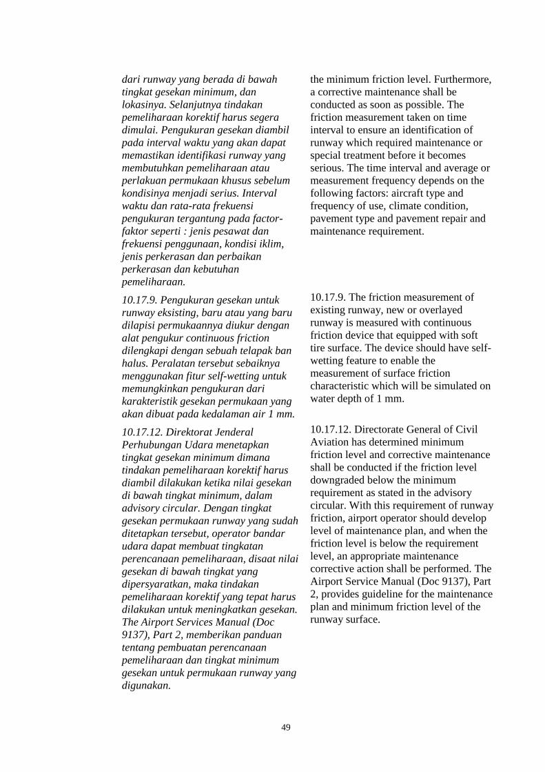
49
dari runway yang berada di bawah
tingkat gesekan minimum, dan
lokasinya. Selanjutnya tindakan
pemeliharaan korektif harus segera
dimulai. Pengukuran gesekan diambil
pada interval waktu yang akan dapat
memastikan identifikasi runway yang
membutuhkan pemeliharaan atau
perlakuan permukaan khusus sebelum
kondisinya menjadi serius. Interval
waktu dan rata-rata frekuensi
pengukuran tergantung pada factor-
faktor seperti : jenis pesawat dan
frekuensi penggunaan, kondisi iklim,
jenis perkerasan dan perbaikan
perkerasan dan kebutuhan
pemeliharaan.
the minimum friction level. Furthermore,
a corrective maintenance shall be
conducted as soon as possible. The
friction measurement taken on time
interval to ensure an identification of
runway which required maintenance or
special treatment before it becomes
serious. The time interval and average or
measurement frequency depends on the
following factors: aircraft type and
frequency of use, climate condition,
pavement type and pavement repair and
maintenance requirement.
10.17.9. Pengukuran gesekan untuk
runway eksisting, baru atau yang baru
dilapisi permukaannya diukur dengan
alat pengukur continuous friction
dilengkapi dengan sebuah telapak ban
halus. Peralatan tersebut sebaiknya
menggunakan fitur self-wetting untuk
memungkinkan pengukuran dari
karakteristik gesekan permukaan yang
akan dibuat pada kedalaman air 1 mm.
10.17.9. The friction measurement of
existing runway, new or overlayed
runway is measured with continuous
friction device that equipped with soft
tire surface. The device should have self-
wetting feature to enable the
measurement of surface friction
characteristic which will be simulated on
water depth of 1 mm.
10.17.12. Direktorat Jenderal
Perhubungan Udara menetapkan
tingkat gesekan minimum dimana
tindakan pemeliharaan korektif harus
diambil dilakukan ketika nilai gesekan
di bawah tingkat minimum, dalam
advisory circular. Dengan tingkat
gesekan permukaan runway yang sudah
ditetapkan tersebut, operator bandar
udara dapat membuat tingkatan
perencanaan pemeliharaan, disaat nilai
gesekan di bawah tingkat yang
dipersyaratkan, maka tindakan
pemeliharaan korektif yang tepat harus
dilakukan untuk meningkatkan gesekan.
The Airport Services Manual (Doc
9137), Part 2, memberikan panduan
tentang pembuatan perencanaan
pemeliharaan dan tingkat minimum
gesekan untuk permukaan runway yang
digunakan.
10.17.12. Directorate General of Civil
Aviation has determined minimum
friction level and corrective maintenance
shall be conducted if the friction level
downgraded below the minimum
requirement as stated in the advisory
circular. With this requirement of runway
friction, airport operator should develop
level of maintenance plan, and when the
friction level is below the requirement
level, an appropriate maintenance
corrective action shall be performed. The
Airport Service Manual (Doc 9137), Part
2, provides guideline for the maintenance
plan and minimum friction level of the
runway surface.

50
1.17.4.3 Advisory Circular CASR Part 139-23
5.1 Jadwal Evaluasi Kekesatan
Perkerasan
Pelaksana bandar udara dan pengguna
lalu lintas udara harus menjadwalkan
periode pemeliharaan kekesatan
permukaan perkerasan.
Dalam pelaporan hasil pengukuran
kekesatan harus berisikan informasi
sebagai berikut:
a) Lokasi bandar udara
b) Waktu pelaksanaan pengukuran
(tanggal dan jam)
c) Landas pacu yang diukur (disertai
sketsa layout landas pacu dan
nomor dan arah landas pacu)
d) Jarak jalur lintasan pengukuran
terhadap asrunway
e) Kecepatan pengukuran yang
diterapkan
f) Kondisi permukaaan perkerasan
landas pacu
g) Rata-rata tingkat kekesatan per
jalur untuk masing-masing
pengukuran.
h) Hasil semua pengukuran kekesatan
untuk masing-masing jalur
pengukuran.
5.1 Schedule of Pavement Friction
Evaluation
The airport operator and air traffic user
shall make a periodic schedule for
maintenance of the pavement friction.
In regards to the result of friction
measurement shall include the following
information:
a) Airport location
b) Time of measurement (date and
time)
c) The measured runway (including
runway layout and runway
designation number and runway
direction)
d) The distance of runway
measurement track
e) The speed of measurement
f) The condition of pavement surface
g) The average of friction level on each
track
h) The result of all friction
measurement on each track
5.1 Jadwal Evaluasi Kekesatan
Perkerasan
Tabel 5.1. Frekuensi survey pengecekan
kekesatan
Frekuensi
Pendaratan
Per Hari
Pengecekan
Rutin
< 15 1 tahun
16 – 30 6 bulan
31 – 90 3 bulan
91 – 150 1 bulan
151 – 210 2 minggu
>210 1 minggu
5.1 The Schedule of Pavement Friction
Evaluation
Table 5.1. Frequency of friction check
survey
Landing
Frequency Per
Day
Schedule
< 15 1 year
16 – 30 6 month
31 – 90 3 month
91 – 150 1 month
151 – 210 2 week
>210 1 week

51
5.2. Evaluasi Kekesatan perkerasan
tanpa bantuan alat
Evaluasi secara visual mengenai tingkat
kekesatan permukaan perkerasan
prasarana sisi udara tidak dapat
diandalkan secara penuh untuk menilai
tingkat kekesatan permukaan prasarana
sisi udara tersebut.
Pelaksana bandar udara yang
mengoperasikan pesawat jenis jet harus
mengatur jadwal pengujian kekesatan
dengan menggunakan peralatan.
Pada prinsipnya, inspeksi secara visual
hanya dilakukan untuk menilai dan
mencatat kondisi permukaan seperti
terdapatnya genangan air, alur
kerusakan serta kondisi struktur
perkerasan.
Dari uraian ini dapat disimpulkan
bahwa penilaian kekesatan secara
visual semata hanya dilakukan sebagai
langkah inspeksi dan bukan merupakan
suatu kesimpulan dari kondisi
permukaan perkerasan.
Pengujian dengan peralatan dan teknisi
yang berpengalaman harus tetap
dilakukan sesuai jadwal pada tabel 5.1
diatas dengan gambaran pengujian
sebagaimana disajikan dalam
Appendiks B.
5.2. Evaluation of pavement friction
without equipment
A visual evaluation of friction level on
pavement surface is not reliable to
measure the friction level of airside area.
The airport operator with jet aircraft
operation shall schedule a friction
measurement using equipment.
In principle, the visual evaluation only
conducts for the purpose of evaluating
and documenting the surface condition if
water ponding exists and sign of
pavement damage.
According to the explanation, it can be
concluded that the visual measurement of
friction is conducted only for inspection
and not as a result of the pavement
surface condition.
A test using equipment and experienced
technician shall be conducted as
scheduled in table 5.1 and test illustration
as described on appendix B.

52
Tabel 5.2. Klasifikasi tingkat kekesatan permukaaan perkerasan landas pacu untuk
berbagai alat ukur yang digunakan.
Jenis Alat Uji
65 km/h (40 mph) 95 km/h (40 mph)
Mini
mal
Perawa
tan
Konstruk
si Baru
Minim
al
Perawa
tan
Konstruk
si Baru
Mu(myu)- Meter 0.42 0.52 0.72 0.26 0.34 0.66
Dynatest
Consulting, Inc.
Runway Friction
Tester
0.50 0.60 0.82 0.41 0.54 0.72
Airport
Equipment Co.
Skiddometer
0.50 0.60 0.82 0.34 0.47 0.74
Airport Surface
Friction Tester 0.50 0.60 0.82 0.34 0.47 0.74
Airport
Technology USA
Safegate
Friction Tester
0.43 0.60 0.82 0.34 0.47 0.74
Findlay, Irvine,
Ltd. Griptester
Friction Meter
0.48 0.53 0.74 0.24 0.36 0.64
Tatra Friction
Tester 0.48 0.57 0.76 0.42 0.52 0.67
Norsemeter
RUNAR
(operated at
fixed 16% slip)
0.45 0.52 0.69 0.32 0.42 0.63
The translation is as follows:
Table 5.2. Friction level classification for runway pavement surface using
different device measurement.
Measurement
Device
65 km/h (40 mph) 95 km/h (40 mph)
Mini
mal
Maint
enanc
e
New
Construc
tion
Mini
mal
Mainte
nance
New
Construc
tion
Mu(myu)- Meter 0.42 0.52 0.72 0.26 0.34 0.66
Dynatest
Consulting, Inc.
Runway Friction
Tester
0.50 0.60 0.82 0.41 0.54 0.72
Airport
Equipment Co.
Skiddometer
0.50 0.60 0.82 0.34 0.47 0.74
Airport Surface
Friction Tester 0.50 0.60 0.82 0.34 0.47 0.74
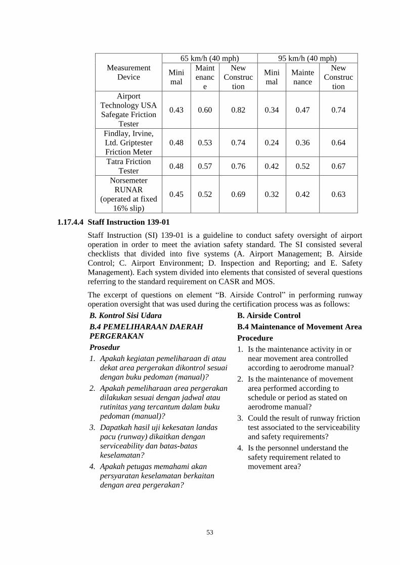
53
Measurement
Device
65 km/h (40 mph) 95 km/h (40 mph)
Mini
mal
Maint
enanc
e
New
Construc
tion
Mini
mal
Mainte
nance
New
Construc
tion
Airport
Technology USA
Safegate Friction
Tester
0.43 0.60 0.82 0.34 0.47 0.74
Findlay, Irvine,
Ltd. Griptester
Friction Meter
0.48 0.53 0.74 0.24 0.36 0.64
Tatra Friction
Tester 0.48 0.57 0.76 0.42 0.52 0.67
Norsemeter
RUNAR
(operated at fixed
16% slip)
0.45 0.52 0.69 0.32 0.42 0.63
1.17.4.4 Staff Instruction 139-01
Staff Instruction (SI) 139-01 is a guideline to conduct safety oversight of airport
operation in order to meet the aviation safety standard. The SI consisted several
checklists that divided into five systems (A. Airport Management; B. Airside
Control; C. Airport Environment; D. Inspection and Reporting; and E. Safety
Management). Each system divided into elements that consisted of several questions
referring to the standard requirement on CASR and MOS.
The excerpt of questions on element ―B. Airside Control‖ in performing runway
operation oversight that was used during the certification process was as follows:
B. Kontrol Sisi Udara
B.4 PEMELIHARAAN DAERAH
PERGERAKAN
Prosedur
1. Apakah kegiatan pemeliharaan di atau
dekat area pergerakan dikontrol sesuai
dengan buku pedoman (manual)?
2. Apakah pemeliharaan area pergerakan
dilakukan sesuai dengan jadwal atau
rutinitas yang tercantum dalam buku
pedoman (manual)?
3. Dapatkah hasil uji kekesatan landas
pacu (runway) dikaitkan dengan
serviceability dan batas-batas
keselamatan?
4. Apakah petugas memahami akan
persyaratan keselamatan berkaitan
dengan area pergerakan?
B. Airside Control
B.4 Maintenance of Movement Area
Procedure
1. Is the maintenance activity in or
near movement area controlled
according to aerodrome manual?
2. Is the maintenance of movement
area performed according to
schedule or period as stated on
aerodrome manual?
3. Could the result of runway friction
test associated to the serviceability
and safety requirements?
4. Is the personnel understand the
safety requirement related to
movement area?

54
The certification assessment process for Adisutjipto Airport was conducted by the
Directorate of Airport personnel on 10 until 13 March 2015. The assessment process
referred to Staff Instruction 139-01. The findings related to runway operation and
maintenance was as follows:
Belum tersedia program manajemen perkerasan / Pavement Management
System (PMS), tidak adanya suatu sistem pemeliharaan konstruksi yang
terencana, tepat dan terdokumentasi untuk mempertahankan konstruksi
perkerasan yang mempunyai kinerja tinggi, handal serta berkelanjutan.
There was no Pavement Management System (PMS), which is maintenance
systems that appropriately planned, executed, and documented to ensure
sustainability of pavement construction.
Belum tersedia standar dan prosedur pelaksanaan pekerjaan pemeliharaan /
perbaikan pada kondisi khusus / mendadak.
There was no standard and procedure to conduct maintenance/repair on
special/urgent condition.
The investigation did not find the DGCA finding related to the inspection of runway
including the runway friction check.
1.17.4.5 Advisory Circular 170-02
The DGCA has Directorate of Navigation responsible for regulating the air traffic
services. The Directorate of Navigation issued several regulations and standards.
The relevant regulations and standards are as follows:
7.4 ESSENTIAL INFORMATION ON AERODROME CONDITIONS
7.4.1 Essential information on aerodrome conditions is information necessary to
safety in the operation of aircraft, which pertains to the movement area or any
facilities usually associated therewith. For example, construction work on a taxi
strip not connected to the runway-in-use would not be essential information to any
aircraft except one that might be taxied in the vicinity of the construction work. As
another example, if all traffic must be confined to runways, that fact should be
considered as essential aerodrome information to any aircraft not familiar with the
aerodrome.
7.4.2 Essential information on aerodrome conditions shall include information
relating to the following:
a) construction or maintenance work on, or immediately adjacent to the
movement area;
b) rough or broken surfaces on a runway, a taxiway or an apron, whether
marked or not;
c) snow, slush or ice on a runway, a taxiway or an apron;
d) water on a runway, a taxiway or an apron;
e) snow banks or drifts adjacent to a runway, a taxiway or an apron;
f) other temporary hazards, including parked aircraft and birds on the ground
or in the air;
g) failure or irregular operation of part or all of the aerodrome lighting system;
h) any other pertinent information.

55
Note.— Up-to-date information on the conditions on aprons may not always be
available to the aerodrome control tower. The responsibility of the aerodrome
control tower in relation to aprons is, with respect to the provisions of 7.4.1 and
7.4.2, limited to the transmission to aircraft of the information which is provided to
it by the authority responsible for the aprons.
7.4.3 Essential information on aerodrome conditions shall be given to every aircraft,
except when it is known that the aircraft already has received all or part of the
information from other sources. The information shall be given in sufficient time for
the aircraft to make proper use of it, and the hazards shall be identified as distinctly
as possible.
Note.— ―Other sources‖ include NOTAM, ATIS broadcasts, and the display of
suitable signals.
12.3 ATC PHRASEOLOGIES
12.3.1 General
12.3.1.10 AERODROME INFORMATION
g) RUNWAY REPORT AT (observation time) RUNWAY (number) (type of
precipitant) UP TO (depth of deposit) MILLIMETRES. BRAKING ACTION GOOD
(or MEDIUM TO GOOD, or MEDIUM, or MEDIUM TO POOR, or POOR or
UNRELIABLE) [and/or BRAKING COEFFICIENT (equipment and number)];
h) BRAKING ACTION REPORTED BY (aircraft type) AT (time) GOOD (or
MEDIUM, or POOR);
i) BRAKING ACTION [(location)] (measuring equipment used), RUNWAY
(number), TEMPERATURE [MINUS] (number), WAS (reading) AT (time);
j) RUNWAY (or TAXIWAY) (number) WET [or DAMP, WATER PATCHES,
FLOODED (depth), or SNOW REMOVED (length and width as applicable), or
TREATED, or COVERED WITH PATCHES OF DRY SNOW (or WET SNOW, or
COMPACTED SNOW, or SLUSH, or FROZEN SLUSH, or ICE, or ICE
UNDERNEATH, or ICE AND SNOW, or SNOWDRIFTS, or FROZEN RUTS AND
RIDGES)];
1.18 Additional Information
1.18.1 Reporting of Runway Surface Condition
ICAO Annex 14 – Aerodromes, Volume I – Aerodrome Design and Operations
2.9 Condition of the movement area and related facilities
2.9.1 Information on the condition of the movement area and the operational status
of related facilities shall be provided to the appropriate aeronautical information
service units, and similar information of operational significance to the air traffic
services units, to enable those units to provide the necessary information to arriving
and departing aircraft. The information shall be kept up to date and changes in
conditions reported without delay.

56
2.9.2 The condition of the movement area and the operational status of related
facilities shall be monitored and reports on matters of operational significance
affecting aircraft and aerodrome operations shall be provided in order to take
appropriate action, particularly in respect of the following:
a) construction or maintenance work;
b) rough or broken surfaces on a runway, a taxiway or an apron;
c) snow, slush or ice on a runway, a taxiway or an apron;
d) water on a runway, a taxiway or an apron;
e) snow banks or drifts adjacent to a runway, a taxiway or an apron;
f) anti-icing or de-icing liquid chemicals or other contaminants on a runway,
taxiway or apron;
g) other temporary hazards, including parked aircraft;
h) failure or irregular operation of part or all of the aerodrome visual aids; and
i) failure of the normal or secondary power supply.
2.9.3 To facilitate compliance with 2.9.1 and 2.9.2, inspections of the movement
area shall be carried out each day at least once where the code number is 1 or 2 and
at least twice where the code number is 3 or 4.
2.9.6 Information that a runway or portion thereof may be slippery when wet shall
be made available.
Note.— The determination that a runway or portion thereof may be slippery when
wet is not based solely on the friction measurement obtained using a continuous
friction measuring device. Supplementary tools to undertake this assessment are
described in the Airport Services Manual (Doc 9137), Part 2.
2.9.7 Notification shall be given to aerodrome users when the friction level of a
paved runway or portion thereof is less than that specified by the State in
accordance with 10.2.3.
10.2 Pavements
10.2.3 A paved runway shall be maintained in a condition so as to provide surface
friction characteristics at or above the minimum friction level specified by the State.
10.2.4 Runway surface friction characteristics for maintenance purposes shall be
periodically measured with a continuous friction measuring device using self-
wetting features and documented. The frequency of these measurements shall be
sufficient to determine the trend of the surface friction characteristics of the runway.
ICAO Annex 15 – Aeronautical Information Services
8.1 Pre-flight information
8.1.1 At any aerodrome/heliport normally used for international air operations,
aeronautical information essential for the safety, regularity and efficiency of air
navigation and relative to the route stages originating at the aerodrome/heliport
shall be made available to flight operations personnel, including flight crews and
services responsible for pre-flight information.
57
8.1.2 Aeronautical information provided for pre-flight planning purposes at the
aerodromes/heliports referred to in 8.1.1 shall include relevant:
a) elements of the Integrated Aeronautical Information Package;
b) maps and charts.
Note.— The documentation listed in a) and b) may be limited to national
publications and when practicable, those of immediately adjacent States, provided a
complete library of aeronautical information is available at a central location and
means of direct communications are available between the aerodrome AIS unit and
that library.
8.1.2.1 Additional current information relating to the aerodrome of departure shall
be provided concerning the following:
a) construction or maintenance work on or immediately adjacent to the
manoeuvring area;
b) rough portions of any part of the manoeuvring area, whether marked or not,
e.g. broken parts of the surface of runways and taxiways;
c) presence and depth of snow, ice or water on runways and taxiways, including
their effect on surface friction;
d) snow drifted or piled on or adjacent to runways or taxiways;
e) parked aircraft or other objects on or immediately adjacent to taxiways;
f) presence of other temporary hazards;
g) presence of birds constituting a potential hazard to aircraft operations;
h) failure or irregular operation of part or all of the aerodrome lighting system
including approach, threshold, runway, taxiway, obstruction and
manoeuvring area unserviceability lights and aerodrome power supply;
i) failure, irregular operation and changes in the operational status of SSR,
ADS-B, ADS-C, CPDLC, D-ATIS, D-VOLMET, radio navigation services,
VHF aeromobile channels, RVR observing system, and secondary power
supply; and
j) presence and operation of humanitarian relief missions, such as those
undertaken under the auspices of the United Nations, together with any
associated procedures and/or limitations applied thereof.
ICAO Document 9137 – Airport Services Manual, Part 2 – Pavement Surface
Conditions
3.1.6 The criteria used by a State for evaluating runway surfaces should be
published in the State’s aeronautical information publication (AIP). When a runway
surface that does not meet the criteria is found, a NOTAM should be issued until
such time as corrective action has been taken.
3.2.11 States should specify three friction levels as follows:
a) a design level which establishes the minimum friction level for a newly
constructed or resurfaced runway surface;

58
b) a maintenance friction level below which corrective maintenance action
should be considered; and
c) a minimum friction level below which the information that a runway may be
slippery when wet should be made available and corrective action initiated.
ICAO Circular 319 – Assessment, Measurement and Reporting of Runway
Surface Conditions
Figure 7-2: Key participants in the gathering and provision of runway friction data
Maintenance (Functional)
Aerodrome (1) ATC (2) Flight Crew (3)
Operatives Management
Gathers
Information
Interprets Information
and
Takes Action
Operational (Contaminated)
Aerodrome (1) ATC (2) Flight Crew (3)
Gathers Information Transmit Information
Interpret Information
and
Makes Decision
1.19 Useful or Effective Investigation Techniques
The investigation was conducted in accordance with the KNKT approved policies
and procedures, and in accordance with the standards and recommended practices of
Annex 13 to the Chicago Convention.

59
2 ANALYSIS
The investigation based on the factual data gathered from flight recorders, interview,
and other related data. The investigation also utilized several related and current
manuals uses by the operators, CASR, MOS and ICAO. The investigation is focused
on the factors contributed to the runway excursion and other significant issues.
Therefore, the analysis will focus on the following topics:
Decision to land;
Factors affecting landing distance;
Landing distance calculation;
Braking Action Assessment;
Passenger Evacuation.
2.1 Decision to land
After received weather information from the Automatic Terminal Information
Services (ATIS) the PF decided to land with flaps 40 and auto-brake max. When the
aircraft approaching altitude 2,000 feet, the pilots noticed cumulonimbus cloud over
Yogyakarta as indicated by magenta figure on the weather radar and the PF decided
to follow wind shear precaution recommendation as described on the Flight Crew
Operations Manual (FCOM) to use flaps 30 for landing. This change of landing flap
configuration would increase the landing speed and the landing distance. The
landing speed for the estimated landing weight of 63,900 kg and flaps 30 was 141
knots. There was no recalculation of the required landing distance following the
landing configuration changing.
The recommended elements of a stabilized approach stated in the FCOM, described
that the approach in VMC below 500 feet, the aircraft should be in the correct flight
path, approach speed deviation of +10 knots to -5 knots are acceptable if the
airspeed is trending toward approach speed and all briefings and checklists have
been conducted.
The sequence of events below 500 feet when the PF flown the aircraft manually
were as follows:
At 07:59:43 UTC, at altitude 381 feet, the N1s were at approximately 60%
and the speed was at 157 knots. At altitude 87 feet, the N1s were increased to
approximately 70% followed by the speed increased from 153 knots to 159
knots at 10 feet. At this time the tailwind recorded 6 knots. The aircraft
passed altitude 50 feet with speed of 153 knots then at altitude 10 feet the
speed increased to 159 knots.
At 07:59:52 UTC, at 229 feet, the PM advised the PF to fly right and was
acknowledged by the PF.
The time interval between the aircraft passed altitude of 10 feet to touchdown
was 6 seconds and the speed was 154 knots.
60
The decision to land or go around basically rests to the PIC assessment to the
possibility of critical condition on landing. The CRM principle requires the PM to
callout for any deviation and to take any action if there is no acknowledgement from
the PF. In this particular approach, there was no discussion between the pilots
concerning to the landing distance following the change of the landing configuration
to use flaps 30 for the existing condition, and there was no callout from the PM
when the speed was 13 knots above the approach speed. The speed was an indication
that one of the stabilize approach element was not achieved and required go around.
A combination of the absence of landing distance calculation for landing
configuration with flap 30 and callout of speed above the approach speed might
cause the pilots did not aware of the required landing distance for the existing
condition and decided to continue landing.
2.2 Factors Affecting Landing Distance
According to FCTM 6.32 Factor Affecting Landing Distance, several factors that
affecting the landing distance include the height and speed over the threshold, glide
slope angle, landing flare, lowering the nose to the runway, use of reverse thrust,
speed brakes, wheel brakes and surface conditions of the runway. The reverse thrust
and speed brake drag are most effective during the high-speed portion of the
landing. Deploy the speed brake lever and activate reverse thrust with as little time
delay as possible. Moreover, floating above the runway before touchdown must be
avoided because it uses a large portion of the available runway.
As of FCTM 6.33 Factors Affecting Landing Distance (Typical) describes that
floating above the runway, wheel brakes and reverser are three significant factors
affecting the landing distance.
Significant events from altitude of 200 feet to touchdown
From approximately 200 feet to 10 feet, the average tail wind was 6 knots.
08:00:16 UTC, the FDR data recorded that the aircraft touched down 6 seconds
after passed 10 feet with speed of 154 knots or 13 knots above Vref. The 6
seconds floating resulted in the aircraft touch down at approximately 730
meters from the beginning runway 09 threshold or 427 meters beyond the
touchdown zone aim point. The prolonged touchdown for 6 seconds was the
factor that affecting additional landing distance.
Two seconds after the aircraft touched down, the thrust reversers and the
spoilers deployed and auto-brake active with the brake pressure up to 2,900 psi
at 7 seconds after touchdown.
08:00:28 UTC, the manual brake was applied with intention to increase the
brake pressure. The FDR recorded average brake pressure dropped to
approximately 785 psi for 3 seconds and the longitudinal acceleration increased
(less deceleration). The less deceleration was consistent with lower brake
pressure application.

61
The FCTM 6.37 Transition to Manual Braking described that the transition
from auto brake to manual brake depends on airplane deceleration rate, runway
conditions and stopping requirements. When transitioning to manual braking,
use reverse thrust as required until taxi speed. Immediately after main gear
touchdown, smoothly apply a constant brake pedal pressure for the desired
braking. For short or slippery runways, use full brake pedal pressure and do not
attempt to modulate, pump or improve the braking by any other special
techniques and modulating the brake pedals could affecting the braking
efficiency is lost.
08:00:33 UTC, the reverser stowed for seven seconds at approximately 76
knots, while the recommended speed to stow the reversers was below 60 knots.
The FDR data showed that the longitudinal acceleration was at -0.03 G, even
though the brake pressure was increased to more than 2,000 psi. It can be
concluded that stowing the thrust reversers resulted in less deceleration.
The FDR recorded, the thrust reversers were deployed, followed by all spoiler
deployment and auto-brake activation with the average brake pressure of
approximately 2,494 psi and N1 84.8%. The average of longitudinal acceleration
was -0.27 G for 8 seconds. The deceleration rate with maximum auto-brake
selection of 0.44 G as calculated on chapter 1.17.1.9 did not achieve with brake
pressure and thrust reversers close to maximum. The investigation considered
external factors reducing the deceleration rate such as the runway friction.
It can be concluded that there were four conditions affecting the landing distance,
specifically the aircraft floated for about 6 seconds and touched down at the end of
the touchdown zone, 427 meter beyond the aim point, after bouncing once; the
airspeed at touchdown was 13 knots above Vref plus there was average tailwind of 6
knots; the thrust reversers were stowed at a higher than recommended speed and
there was little braking for about 305 meter after the autobrakes were disconnected;
and the wet runway conditions resulted in less deceleration.
2.3 Landing Distances
The Boeing FCOM provides the normal configuration distance tables as advisory
information to help determine the actual landing distance performance of the
airplane for different runway surface conditions and brake configurations.
The Indonesia MOS 139-23 stated that the definition for wet runway when the
surface is soaked but there is no standing water. According to the Boeing FCTM, the
braking action on wet runway condition is classified as good.
Since the airport operator did not issue the runway friction level therefore, the
analysis applies several landing distance calculations with assumption of Good and
Medium Braking Action for the existing aircraft landing weight, landing
configuration and environmental condition.
The calculation of landing distance based on normal configuration landing distance
table for the actual or assumed condition and the available runway length stated in
the AIP, which was 2,200 meters.

62
Assumption of aircraft landed at touch down area with touchdown speed 13 knots
above Vref on the existing environment condition with good braking action were as
follows:
Component Adjustment (m)
Landing Weight reference (70,000 kg) 1,405
Landing Weight (63,900 kg) -80
Elevation (350 feet) + 12
Wind (tailwind 6 knots) + 120
Slope (0) 0
Temperature (32°C) + 55
Approach speed (Vref + 13) + 144
Thrust reverser (reversers deployed) 0
Total 1,656
Assumption of aircraft landed at 730 meters from beginning runway and touchdown
speed of 13 knots above Vref on the existing environment condition with good
braking action were as follows:
Component Adjustment (m)
Landing Weight reference (70,000 kg) 1,405
Landing Weight (63,900 kg) -80
Elevation (350 feet) + 12
Wind (tailwind 6 knots) + 120
Slope (0) 0
Temperature (32°C) + 55
Approach speed (Vref + 13) + 144
Thrust reverser (reversers deployed) 0
Prolong touchdown (730 m - 305 m) +425
Total 2,081
Based on these calculations, assuming that the runway braking action was good, the
runway was sufficient for the aircraft to stop with existing conditions.

63
Assuming that the runway braking action was medium, and aircraft landed at
touchdown area with correct touchdown speed on the existing environment
condition the calculation are as follows:
Component Adjustment (m)
Landing weight reference 70,000 kg 1,840
Landing weight (63,900 kg) -132
Elevation (350 feet) + 25
Wind (tailwind 6 knots) + 204
Slope (0) 0
Temperature (32°C) + 85
Approach speed (Vref ) 0
Thrust reverser (reversers deployed) 0
Total 2,022
This calculation indicated that, the runway length available was sufficient for the
aircraft to land on the existing environment with correct speed and touchdown point.
The FDR data showed that the aircraft speed was 13 knots above Vref and touched
down at 730 meters from beginning runway, the calculation for the existing
environment condition with medium braking action are as follows:
Component Adjustment (m)
Landing Weight reference (70,000 kg) 1,840
Landing Weight (63,900 kg) -132
Elevation (350 feet) + 25
Wind (tailwind 6 knots) + 204
Slope (0) 0
Temperature (32°C) + 85
Approach speed (Vref + 13) + 182
Thrust reverser (reversers deployed) 0
Prolong touchdown (730 m - 305 m) +425
Total 2,629
Based on these calculations, assuming that the runway braking action was medium,
the available runway was not sufficient for the aircraft to stop with existing
environment and conditions.
Summary of the calculation
Factors affecting landing distance as discussed on Chapter 2.2 of this report
particularly on the application of brake and thrust reverser were not included in the
calculation. However these factors certainly would have affected the aircraft
stopping distance.

64
Based on the landing distance calculations above, it indicated that when the aircraft
was on proper landing profile and touchdown, the aircraft would be able to stop on
the available runway with runway braking action good or medium.
The existing condition of Vref that was 13 knots above the target speed and the
prolong touchdown resulted in the available runway was not sufficient for the
aircraft to stop on medium braking action. On good braking action the runway
available would be sufficient with relatively narrow margin. This narrow margin
might have occupied by the improper application of brake and thrust reversers which
have been discussed on Chapter 2.2. However, there was no information about
runway friction classified as good or medium braking action from the air traffic
controller or the airport operator which can be used as consideration.
2.4 Braking Action Assessment
According to Matrix for runway condition assessment of TALPA ARC as stated on
FCTM Chapter 6, the information of runway condition such as wet runway, slippery
when wet, standing water, etc. can be used to assess the runway-braking action.
Based on MOS 139 Volume I, the information of runway condition shall be reported
to the NOTAM office. The runway friction information was not part of the
information that shall be reported to NOTAM office.
According to ICAO Document 9137 chapter 3.1.6 when the runway surface does not
meet the standard criteria of runway friction level, a NOTAM should be issued until
such time as corrective action has been taken.
Based on ICAO Annex 14 chapter 2.9.1, information on the condition of the
movement area and the operational status of related facilities shall be provided to
the appropriate aeronautical information service units, and similar information of
operational significance to the air traffic services units, to enable those units to
provide the necessary information to arriving and departing aircraft. The
information shall be kept up to date and changes in conditions reported without
delay.
The absence of runway friction level information to the aircraft operators might
reduce the accuracy of the landing distance calculation, either for dispatch planning
or for the pilot during inflight prior to land.

65
2.5 Passenger Evacuation
After the aircraft stopped, the SIC commanded ―ATTENTION CREW ON
STATION‖ and the PIC commanded ―BRACE, BRACE, BRACE‖. The SIC then
asked PIC to set the engine power to idle. All commands during the evacuation shall
only be provided by the PIC unless the PIC incapacitates and the ―BRACE‖
command should be given before impact.
After the aircraft stopped, the pilot called flight attendant and commanded the Flight
Attendant 1 (FA-1) to check the possibility of fire and standby for further instruction
through interphone.
According to the Operation Manual Part-A Chapter 8.3.20.14.4 Initiation of The
Evacuation stated that when the aircraft comes to a full stop under abnormal
conditions the PIC commanded ‖ATTENTION FLIGHT ATTENDANT ON
STATION‖ twice and evaluate situation will decide whether evacuation is required
or not. This command should be followed by the FA-1 check the outside conditions
and coordinated with other FA.
The crew started the APU and selected the APU generator to supply the aircraft
electrical system and also the APU bleed air to supply the air conditioning system.
The QRH for evacuation checklist stated that the engine and APU fire-warning
switch shall be overrode and pulled. It means the engines and APU will be
shutdown. Starting the APU may increase the hazard that induces fire, as there is
possibility of system damage. The APU noise and exhaust gas might also disturbing
the evacuation process.
The evacuation checklist was read and executed approximately three and half
minutes after the aircraft stopped. FCTM Chapter 8.10 on evacuation stated that
―For unplanned evacuations, the captain needs to analyze the situation carefully
before initiating an evacuation order. Quick actions in a calm and methodical
manner improve the chances of a successful evacuation‖. The PIC required three
and half minutes to start evacuation check list while a quick action is required.
The CVR recorded that the evacuation was planned without escape slide and
changed with escape slide. The evacuation was initiated approximately nine minutes
after the aircraft stopped without utilizing over-wing emergency exit window. The
passenger evacuation process completed in approximately eight minutes.
According to the conditions above, the emergency procedures for evacuation was
not performed appropriately. This indicated inadequacy of evacuation training.

66
3 CONCLUSION
3.1 Findings7
1. The aircraft was airworthy prior to the accident.
2. The crew held valid licenses and medical certificates.
3. Both pilots had performed recurrent emergency training on 2015.
4. The PIC acted as PF and the SIC acted as PM.
5. During approach, the pilots noticed cumulonimbus cloud over Yogyakarta as
indicated by magenta figure on the weather radar and decided to follow wind
shear precaution recommendation as described on the Flight Crew Operations
Manual (FCOM) to use flaps 30 for landing.
6. The aircraft landed with configuration of flap 30, auto-brake MAX, landing
weight of 63,900 kg and Vref of 141 knots.
7. On approach the N1s value increased from 60% to 70%, resulted in the speed
increased from 153 knots to 159 knots.
8. On short final, the PM advised the PF to fly right and acknowledged by PF.
9. The conditions during landing were runway wet and tail wind of 6 knots.
10. The interval from altitude of 10 feet to touchdown was 6 seconds and
according to the FDR data, the aircraft touched down at 730 meters from the
beginning runway 09.
11. The aircraft touched down with the speed of 154 knots followed by RAAS
aural "Four Thousand Remaining".
12. A combination of the absence landing distance calculation for landing
configuration with flap 30 and callout of speed above the Vref might cause the
pilots did not aware of the required landing distance for the existing condition
and decided to continue landing.
13. Based on the landing distance calculations indicated that when the aircraft was
on proper landing profile and touchdown, the aircraft would be able to stop on
the available runway with runway braking action good or medium.
14. The existing condition of Vref that was 13 knots above the target speed and the
prolong touchdown, resulted in the available runway was not sufficient for the
aircraft to stop on medium braking action. On good braking action the runway
available would be sufficient with relatively narrow margin. This narrow
margin might have occupied by the improper application of brake and thrust
reversers.
7 Findings are statements of all significant conditions, events or circumstances in the accident sequence. The findings are
significant steps in the accident sequence, but they are not always causal, or indicate deficiencies. Some findings point
out the conditions that pre-existed the accident sequence, but they are usually essential to the understanding of the
occurrence, usually in chronological order.

67
15. Four conditions which affecting the landing distance were the aircraft floated
for about 6 seconds, and touched down at the end of the touchdown zone, 427
meter beyond the aim point, after bouncing once; the airspeed at touchdown
was 13 knots above Vref plus there was average tailwind of 6 knots; the thrust
reversers were stowed at a higher than recommended speed and there was little
braking for about 305 meter after the autobrakes were disconnected; and the
wet runway conditions resulted in less deceleration.
16. The deceleration rate with maximum auto-brake selection of 0.44 G did not
achieve with brake pressure and thrust reversers close to maximum. The
investigation considered the external factors contributed to the reduction of the
deceleration rate such as runway condition.
17. The aircraft stopped at about 80 meters on the left of runway 09 centerline
extension and about 84 meters from end of runway 09 with the nose landing
gear collapsed, and no one injured in this accident.
18. The aircraft operator had amended the Special Airport Information (SAI) into
Company Airport Briefing (CAB). The special limitation for Adisutjipto
airport which was mentioned in the SAI was not included into CAB. The pilot
referred to the SAI instead of the CAB.
19. The Adisutjipto airport was on airport certification renewal process, the
investigation did not find the DGCA finding related to the inspection of
runway including the runway friction check.
20. Discrepancies on the procedure of friction test between Aerodrome Manual
which stated the test performs annually and the SOP – Runway Friction Test
which the test frequency depend on number of aircraft landing per day.
21. There were different information related to stopway, clearway and RESA
between AIP and the Jeppesen publication.
22. The investigation could not find the documentation of daily runway inspection
conducted on the midday and after the termination of airport operation as on
procedure for the last one-month prior the accident including the observation of
standing water.
23. The last rubber deposit cleaning was performed on 29 October 2015.
24. Runway End Safety Area was not provided in runway 27. The DGCA issued
exemption for this issue by referring to the mitigations performed by airport
operator.
25. The airport operator shall conduct runway friction check in accordance with
the airport operator manual and MOS 139. The last runway friction check was
performed on 2009.
26. The investigation found that there was no activity of the airport operator related
to the hazard identification, risk assessment and mitigation concerning to the
runway surface condition including the friction level.
27. The absence of runway friction level information to the aircraft operators might
reduce the accuracy of the landing distance calculation, either for dispatch
planning or for the pilot during inflight prior to land.

68
28. The weather data for Adisutjipto International Airport was provided by the Air
Force Meteorological Unit that utilized Automatic Weather Observation
System (AWOS).
29. The AWOS monitor display was relayed by a CCTV camera to tower desk
controller and when the visual quality of the monitor display became unclear,
the tower controller has to call meteorology officer to get the latest information
from AWOS.
30. The investigation could not find an approval certificate of Air Traffic Services
provider from Directorate General of Civil Aviation.
31. The evacuation procedures did not performed according to the aircraft operator
SOP which indicated inadequacy of crew evacuation training.
3.2 Contributing Factors8
The absence of landing distance calculation following landing reconfiguration
and the higher speed with no reminder callout might have made the pilots
decided to continue landing.
The conditions of the aircraft floated and eventually touched down at the end
of the touchdown zone 13 knots above Vref with average 6 knots tailwind,
lower brake pressure for 305 meter after the autobrakes were disconnected, and
removal of the thrust reverser application at a higher than recommended speed
along with medium braking action had extended the landing distance.
3.3 Other Safety Issue
The external factors such as runway condition might have contributed to the
reducing of deceleration rate while the brake pressure and thrust reversers were
close to maximum.
8 ―Contributing Factors‖ are those events which alone, or in combination with others, resulted in injury or damage. The
contributing factor is an act, omission, condition, or circumstance which if eliminated or avoided would have prevented
the occurrence or would have mitigated the resulting injuries or damage.

69
4 SAFETY ACTION
At the time of issuing this Final report, the Komite Nasional Keselamatan
Transportasi had been informed PT. Batik Air Indonesia safety actions resulting
from this occurrence.
1. On 6 November 2015, the aircraft operator issued Notice to Pilot (NTP)
number 014/XI/2015 contained the following instructions:
To review NTP number 13/XI/2015 Subject to Wet Season and SSQ
Safety Circular Subject to Safety Precautions on Wet/Rainy Season.
PIC must ensure the crew to do proper dispatch briefing to properly
analyze the flight;
Delay the Take Off and Landing when the windshear is forecast in the
takeoff and approach path;
Delay the takeoff and landing on marginal runway during heavy rain since
all our airports in Indonesia do not have water depth measurement, and
some airports the drainage is poor;
Delay the approach and landing during heavy rain especially at night since
the visibility can be very poor during flare and roll out which increase the
risk of bad runway contact;
Ensure correct performance calculation for takeoff and landing;
Ensure stabilize approach, positive landing, and all stopping device are
functioning;
Carry sufficient fuel to anticipate for holding;
During Enroute keep updating the alternate weather;
PIC must create good CRM and enforce cockpit discipline, "There is no
Pilot Error it is Crew error‖, which means the PIC must encourage good
communications to remind each other mistakes.
2. On 10 November 2015, the aircraft operator issued notices to pilot number
00l/NTPB/Xl/2015 that strongly recommend to all respected Boeing Pilots to
use flap 40 for landing in any airport has landing distance available (LDA) less
than 2500 meters. It should apply in any condition wet or dry.
3. On 12 November 2015, the aircraft operator issued notices to pilot number
002/NTPB/XI/2015. The notice contained instruction in landing configuration
change to consider increasing of safety, correct calculation and acknowledges
by both pilots and changing shall be made no later than leaving Initial
Approach Fix.

70
4. On 13 November 2015, the aircraft operator issued company NOTAM for
operation to Yogyakarta that contained instruction to all pilots for taking
cautions which the end runway 09 or beginning runway 27 is slippery when
wet and do not disengage auto brakes and stowed the reverse thrust until the
aircraft on taxi speed.
5. On 1 December 2015, the aircraft operator issued company Safety Alert that
contained information as follows:
Until the Company Airport Briefing (CAB) is revised and published with
complete information, CAB is considered as temporary invalid.
Until the CAB revision is complete, the Special Airport Information (SAI)
will be the only source of airport information and shall be included in
every trip-kit document.
The A320 fleet shall seek for equivalence in SAI for type specific
information.
6. On 4 December 2015, a Crew member Emergency Training (CET) was
performed to the flight crew of the accident flight.
7. On 14 December 2015, a join Crew Resource Management (CRM) was
performed to the flight crew of the accident flight.
8. On 17 December 2015, the aircraft operator issued safety notice that contained
instruction as follows:
Whenever weather information indicates rain over an aerodrome and or the
runway condition is declared WET or based on relevant data is assumed
WET without BRAKING ACTION; a more conservative Landing
Distance Calculation shall be performed with a safety margin. Such a
result may be achieved by calculating landing distance performance based
on the Medium Reported Braking or (if necessary) Poor Braking Action. If
BRAKING ACTION INFORMATION is available either provided by the
ATC/BMKG/PIREP or any other valid source, the dispatch and pilot shall
use and comply to this information.
The Good Reported Braking Action should be considered only when the
light precipitation is visible on the windshield, or declared and published
by ATC /METAR if provided.
When necessary, Pilot shall consider the need of Maximum Autobrake and
apply the proper Approach, Landing and Deceleration Technique as listed
below, but not limited to:
a. Touchdown on the touchdown point and not more than first 1000ft of
the runway length.
b. Avoid early disconnection of Autobrake (especially with Autobrake
MAX).
c. Avoid modulating the brake, in case of manual brake.
d. Get the taxi speed before reaching the last third of the runway.

71
e. Remind the use of reverse power, maintain reverse thrust as required,
up to maximum, until the airspeed approach 60 knots, if necessary
maintain max reverse before the end of the runway.
f. Remind if the reversers were stowed (too early).
g. To establish common criteria among all Airline operating Narrow
Body Jet Aircraft: for operating on short runway (<2700m), Pilot shall
assure the Approach Flaps is 40/FULL and all braking devices
operative.
h. Comply with the tailwind and cross wind restriction by Manufacture
and Company SOP (Company Airport Briefing)
If the runway surface condition or the precipitation is worse than expected
and leaving an uncertainty, Pilot shall cancel the approach / conduct a
missed approach to make time for another approach preparation.
9. On 10 February 2016, the aircraft operator notified the following safety
actions:
Notified Jepessen to check the discrepancies of the information related to
stopway, clearway and RESA between AIP and Jeppesen publication of
Adisutjipto International Airport.
Improved the simulator training syllabus including evacuation that
highlighted on evacuation sequence.
Conducted join CRM Training flight crew and flight attendant in order to
improve crew coordination during emergency.
Flight attendant emergency training to practice emergency equipment drill.
Implementation of improved emergency training as stated on Operation
Training Manual revision of 2 October 2015.
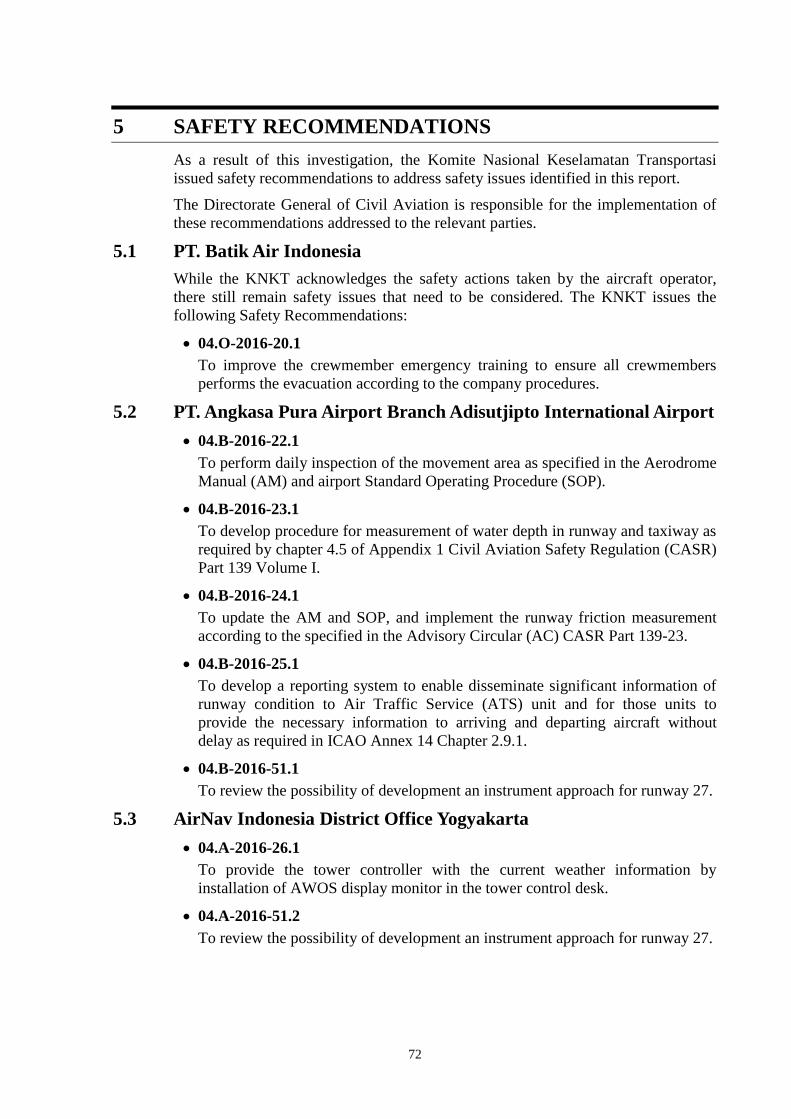
72
5 SAFETY RECOMMENDATIONS
As a result of this investigation, the Komite Nasional Keselamatan Transportasi
issued safety recommendations to address safety issues identified in this report.
The Directorate General of Civil Aviation is responsible for the implementation of
these recommendations addressed to the relevant parties.
5.1 PT. Batik Air Indonesia
While the KNKT acknowledges the safety actions taken by the aircraft operator,
there still remain safety issues that need to be considered. The KNKT issues the
following Safety Recommendations:
04.O-2016-20.1
To improve the crewmember emergency training to ensure all crewmembers
performs the evacuation according to the company procedures.
5.2 PT. Angkasa Pura Airport Branch Adisutjipto International Airport
04.B-2016-22.1
To perform daily inspection of the movement area as specified in the Aerodrome
Manual (AM) and airport Standard Operating Procedure (SOP).
04.B-2016-23.1
To develop procedure for measurement of water depth in runway and taxiway as
required by chapter 4.5 of Appendix 1 Civil Aviation Safety Regulation (CASR)
Part 139 Volume I.
04.B-2016-24.1
To update the AM and SOP, and implement the runway friction measurement
according to the specified in the Advisory Circular (AC) CASR Part 139-23.
04.B-2016-25.1
To develop a reporting system to enable disseminate significant information of
runway condition to Air Traffic Service (ATS) unit and for those units to
provide the necessary information to arriving and departing aircraft without
delay as required in ICAO Annex 14 Chapter 2.9.1.
04.B-2016-51.1
To review the possibility of development an instrument approach for runway 27.
5.3 AirNav Indonesia District Office Yogyakarta
04.A-2016-26.1
To provide the tower controller with the current weather information by
installation of AWOS display monitor in the tower control desk.
04.A-2016-51.2
To review the possibility of development an instrument approach for runway 27.

73
5.4 Directorate General of Civil Aviation
04.R-2016-1.2
To emphasize all aircraft operators comply with stabilize approach criteria.
04.R-2016-27.1
To ensure all aircraft operators calculate the landing distance available is
suitable for the landing distance required on existing condition.
04.R-2016-28.1
To emphasize all aircraft operators implement standard callout procedure on
approach.
04.R-2016-29.1
To emphasize all aircraft operators conduct emergency training to ensure the
crewmember taking appropriate action during emergency.
04.R-2016-30.1
To ensure that the airport operators manual contain the requirement specified in
the CASR Part 139, AC CASR Part 139-23 and Manual of Standard CASR Part
139.
04.R-2016-22.2
To ensure all airport operators conduct inspection of movement area according
to the approved manuals.
04.R-2016-24.2
To ensure all airport operators implement the runway friction measurement
according to the specified in the AC CASR Part 139-23.
04.R-2016-25.2
To include in the Indonesia regulation, the procedure of reporting system from
the airport operator to the ATS unit to enable disseminate significant information
of runway condition to arriving and departing aircraft without delay as required
in ICAO Annex 14 Chapter 2.9.1.
04.R-2016-31.1
To issue approval certificates for the Air Traffic Services providers.
04.R-2016-51.3
To review the possibility of development an instrument approach for runway 27.

74
6 APPENDICES
6.1 Notice to Pilot
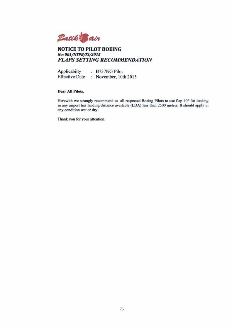
75

76

77
6.2 Company NOTAM

78
6.3 Safety Notice

79

80

81

82
6.4 Safety Plan of Runway End Safety Area Runway 27

83

84

85

86
87

88

89

90

91
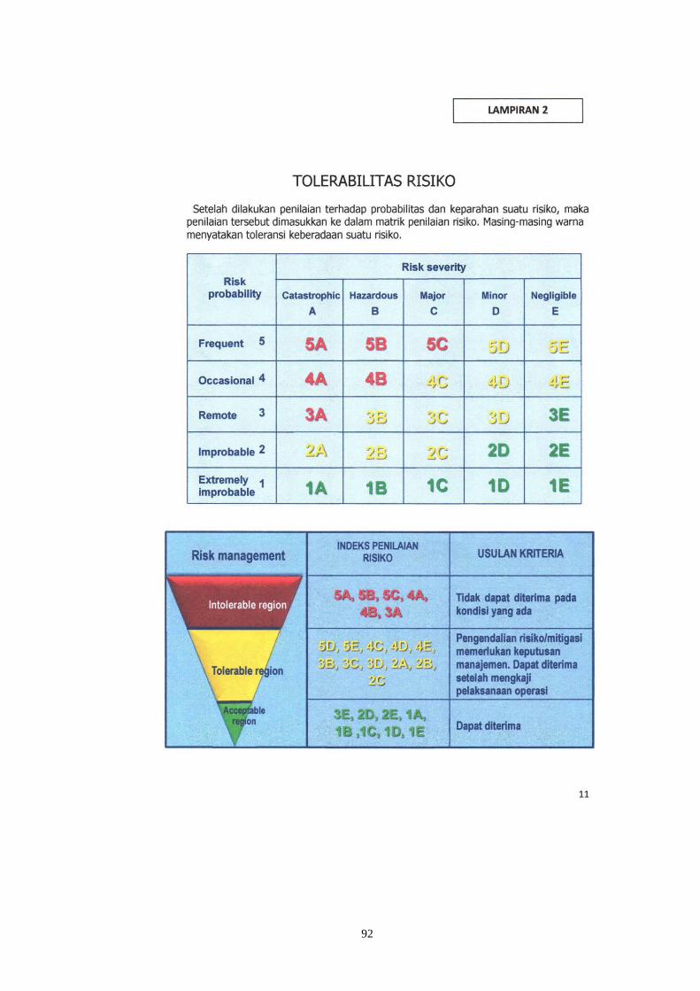
92

1

2

3
6.5 Direct Involve Parties Comments
The comments show the text from the draft report in italic blue text with proposed deletions shown as strikethrough and proposed
additions as underline.
6.5.1 National Transportation Safety Board
NO PAGE COMMENTS KNKT RESPONSE
1. 6 According to the Boeing 737-800/900ER Flight Crew Operations Manual (FCOM)
Chapter PI.20.5, the Vref landing with configuration flap 30 was 141 knots.
Rationale: Please remove the V-Speeds table that is copied from the Boeing Flight Crew
Operations Manual. This manual is Boeing Proprietary and Copyright. Boeing may grant
permission to reproduce limited information from this manual upon request.
Accepted
2. 9 Figure 5: The ILS approach chart issued by Jeppesen
Comment: The revision date on the Jeppesen chart included in Figure 5 is 26 Nov 15.
This event occurred on 6 Nov 15 prior to this revision being published.
Accepted
The ILS chart has been changed to
ILS approach chart provided by
Directorate General of Civil
Aviation on Aeronautical
Information Publication (AIP)
Volume II amendment 43 dated 17
September 2015

4
NO PAGE COMMENTS KNKT RESPONSE
3. 14 1.11.3 Significant Events from Recorders
07:59:23 UTC, Auto pilot and auto throttle disconnected at approximately 700 feet
Rationale: For clarification of the relative sequence of events, Boeing suggests adding the
altitude at which the autoflight systems were disconnected.
Accepted
4. 14 1.11.3 Significant Events from Recorders
08:00:16 UTC, the aircraft touched down with the speed of 154 knots (Vref + 13),
bounced briefly and touched down a second time followed by RAAS aural ―Four
Thousand Remaining‖.
Rationale: For technical correctness, Boeing suggests changing the sentence to reflect that
the aircraft bounced briefly between touchdowns. The bounce is significant because over
200 feet of runway were used for the bounce which delayed the initial application of the
autobrakes and further limited the available deceleration for the aircraft.
Accepted
5. 14 1.11.3 Significant Events from Recorders
08:00:28 UTC, the auto brake disarmed, the average brake pressure dropped to
approximately 785 psi for 3 seconds, until manual braking was applied and the pressure
increased to 3000 psi again, the longitudinal acceleration increased.
Rationale: This section did not include a statement about the use of manual braking which
occurred following the disconnect of the autobrakes and eventually reached 3000 psi.
Accepted
6. 14 1.11.3 Significant Events from Recorders
08:00:33 UTC, the reverser stowed for approximately seven seconds at approximately 76
knots, although they had been reduced from the maximum setting at 91 knots.
Rationale: Clarification. It is important to identify both the speed at which the thrust
reversers started transit from the fully deployed position to the stowed position because
less than maximum thrust reverse was provided during the time of transit.
Accepted
7. 32, 35,
35, 46
1.17.1.6 Boeing 737-800/900ER Flight Crew Operations Manual (page 32)
1.17.1.7 Boeing 737 Quick Reference Handbook (page 35)
1.17.1.8 Flight Crew Training Manual (page 35)
1.17.1.9 Boeing 737-600/700/800/900 Aircraft Maintenance Manual (page 46)
Comment: The above sections are all copied materials from Boeing Copyright and
Boeing Proprietary manuals that may not be reproduced without permission from Boeing.
Accepted
KNKT has rephrased some of
information from the manuals and
the Boeing has granted permission
to use some materials of the
Boeing Proprietary.

5
NO PAGE COMMENTS KNKT RESPONSE
Boeing may grant permission to reproduce limited information from these documents
upon request, but does not authorize the KNKT to publish the information contained in
these sections of the report.
8. 71 2.1 Decision to Land (1st paragraph)
In this particular approach, there was no discussion between the pilots concerning to the
landing distance with flaps 30 for the existing condition, and there was no callout from
the PM when the speed was 15 13 knots above the Vapp Vref.
Rationale: Clarification. The Stabilized Approach speed criteria is related to Vapp, not
Vref. Vapp is Vref plus 5 knots which would have been 146 knots. A 10 knot exceedance
is allowed. The airplane speed reached 159 knots during the approach, which is 13 knots
above Vapp.
Accepted
9. 71 2.2 Factors Affecting Landing Distance (first bullet)
08:00:16 UTC, the FDR data recorded that the aircraft touched down 6 seconds after
passed 10 feet with speed 159 154 knots or 18 13 knots above Vref.
The 6 seconds floating resulted in the aircraft touch down at approximately 773 730
meters from the beginning runway 09 threshold or 468 427 meters beyond the touchdown
zone Aim Point. This condition met the factor that affecting additional landing distance.
Rationale: Our review of the QAR data indicated a touchdown speed of 154 knots which
is also the speed identified as the touchdown speed in Section 1.11.3 and Section 3.1 of
this report. Boeing’s analysis computed a touchdown location 730 meters beyond the
runway threshold. The touchdown zone is considered to be the first third of the runway
and in this case extends 2406 feet (730 meters) passed the runway threshold. Therefore
the airplane touched down at the very end of the touchdown zone, but was 1400 feet (427
meters) beyond the Aim Point.
Accepted
10. 71 2.2 Factors Affecting Landing Distance (second bullet)
Two seconds after the aircraft touched down, the thrust reversers and the spoilers
deployed and auto-brake active with the brake pressure up to 2,900 psi at 7 seconds after
touchdown.
Rationale: For technical correctness, Boeing suggests changing the sentence to indicate
that the brake pressure did not reach 2900 psi until 7 seconds after the aircraft touched
Accepted

6
NO PAGE COMMENTS KNKT RESPONSE
down.
11. 72 2.2 Factors Affecting Landing Distance
It can be concluded that there were three four conditions affecting the landing distance,
which were contrary with the procedures specifically the aircraft floated for about 6
seconds and touched down at the end of the touchdown zone, 1400 feet beyond the aim
point, after bouncing once; the airspeed at touchdown was 13 knots above Vref plus there
was a 5 knot tailwind; the thrust reversers were stowed at a higher than recommended
speed by over 30 knots and there was little braking for about 1000 feet after the
autobrakes were disconnected; and the wet runway conditions resulted in Medium
braking action lower brake pressure and reverser application.
Rationale: The landing distance was affected by the aircraft speed at touchdown, the
location of the final touchdown, the under usage of deceleration devices during the
rollout, and the wet runway conditions.
The airspeed at the touchdown point was 13 knots above Vref which added
approximately 600 feet to the additional runway required to dissipate this excess
energy. Additionally, there was a 5 knot tailwind which required approximately an
additional 550 feet of stopping distance.
The aircraft touched down at the very end of the landing zone and 1400 feet beyond
the aim point, leaving less of the available runway for deceleration.
An early flare at 80 feet instead of the recommended 20 feet was likely a contributor to
the long touchdown point.
The deceleration devices were not fully utilized. The flight crew stowed the thrust
reversers at a 91 knots instead of the recommended 60 knots. There was very little
manual braking for about 6 seconds or about 1000 feet after the autobrakes were
disengaged. The transition from reverse to forward thrust was made at 75 knots
instead of at the recommended taxi speed.
The wet runway conditions resulted in an airplane braking coefficient that is
equivalent to Medium braking action.
Accepted

7
NO PAGE COMMENTS KNKT RESPONSE
12. 73 2.3 Landing Distances
Assumption of aircraft landed at 773 730 meters from beginning runway and touchdown
speed of 15 13 knots above Vref on the existing environment conditions with good
braking action and maximum autobrakes were as follows:
Rationale: For technical correctness, Boeing suggests changing the analysis to assume a
touchdown speed of 13 knots above Vref since the QAR data shows this was true during
the event landing. Note there are multiple locations in this section that use 15 knots and
Boeing recommends revising them all to 13 knots.
Boeing analysis also indicates the airplane touched down 730 meters from the runway
threshold. It appears the calculations in section 2.3 were performed assuming maximum
autobrakes were used. This should be stated as well.
Accepted
13. 74 2.3 Landing Distances
However, there was no information about runway friction classified as good or medium
braking action which can be used as consideration.
Rationale: Boeing conducted a runway friction analysis and provided this to the NTSB
and the operator. Our analysis computer an airplane braking coefficient of 0.1, which is
equivalent to a braking action of Medium.
The information of runway
braking action discussed in this
case was from the air traffic
controller or airport operator.
Correction has been made on 2.3.
14. 77 3.1 Findings
10. The interval from altitude of 10 feet to touchdown was 6 seconds and according to
FDR data, the aircraft touched down at 773 730 meters from the beginning runway 09.
Rationale: Boeing’s calculations show the aircraft touched down 730 meters from the
runway 09 threshold.
Accepted
15. 77 3.1 Findings
14. The existing condition of Vref that was 15 13 knots above the target speed and the
prolong touchdown…
Rationale: The touchdown speed of 154 knots stated in section 1.11.3 and item 10 in
section 3.1 is 13 knots above the target Vref.
Accepted
16. 77 3.1 Findings (item 15)
Four Three conditions which were the aircraft floated for about 6 seconds and touched
down at the very end of the touchdown zone and 1400 feet past the aim point; the
Accepted

8
NO PAGE COMMENTS KNKT RESPONSE
airspeed at touchdown was 13 knots above Vref and there was a 5 knot tailwind; lower
brake pressure for about 1000 feet after the autobrakes were disconnected and stowing of
the thrust reversers at a higher than recommended speed; and wet runway conditions that
resulted in an airplane braking coefficient equivalent to Medium braking action
application affected the landing distance.
Rationale: Similar to the comment made regarding Section 2.2, there were four conditions
that affected the landing distance. These were the long touchdown point, the high speed at
touchdown along with a tailwind, the under-utilization of the deceleration devices and the
medium braking action due to the wet runway conditions.
17. 79 3.2 Contributing Factors (second bullet)
The conditions of the aircraft floated and eventually touched down at the end of the
touchdown zone 13 knots above Vref with a 5 knot tailwind, lower brake pressure for
1000 feet after the autobrakes were disconnected, and removal of the thrust reverser
application at a higher than recommended speed along with medium braking action had
extended the landing distance.
Rationale: Similar to the comment made above, there were four conditions that affected
the landing distance. These were the long touchdown point, the high speed at touchdown
along with a tailwind, the under-utilization of the deceleration devices and the medium
braking action due to the wet runway conditions.
Accepted
KNKT used the average of
tailwind value and converted the
distance using meter.
18. 83 5 Safety Recommendations (page 83)
Comment: There are several areas that Boeing believes are relevant to the event and
important to mention in this report that are not currently included:
Boeing understands that there is currently no approach available to runway 27. Adding
approaches to this runway would prevent the need for a flight crew to land on runway
09 with a tailwind. We suggest that the KNKT consider a recommendation to develop
an approach to runway 27.
Boeing suggests the KNKT consider adding a recommendations to address go-around
decision making, such as identifying a go-around point or latest touchdown point
during the landing distance assessment. This type of preparation could have resulted in
Accepted
Batik Air has issued safety action
for this particular issue, therefore
KNKT did not issue
recommendation.

9
NO PAGE COMMENTS KNKT RESPONSE
a go around decision when the end of the landing zone was reached at high speed
instead of an attempt to continue landing.
6.5.2 Directorate General of Civil Aviation
NO PAGE COMMENTS KNKT RESPONSE
1. viii ABBREVIATIONS AND DEFINITION
ATIS: Aerodrome Automatic Terminal Information System
Accepted
2. 10 1.10 Aerodrome Information
Airport Certificate: 018/SBU-DBU/VII/2010 018/SBU-DBU/XI/2015 Accepted
3. 11 Figure 7: The airport layout published on Aeronautical Information Publication
The airport layout is using aerodrome chart amendment 38(20 February 2014),
meanwhile the current chart is amendment 41 (2 April 2015)
KNKT has not received the
amendment 41 of the airport
layout.
4. 84 04.R-2016-1.2
To emphasize all aircraft operators comply with stabilize approach criteria.
On 23 April 2007 DGCA has issued safety circular number AU/2162/DSKU/04/EK/2007
with subject implementation of Approach And Landing Accident Reduction (ALAR)
Tool Kit in order to prevent serious incident and accident during landing.
Implementation of the safety circular is monitored by the Directorate of Airworthiness
and Aircraft Operation through aircraft operator training program agreement and also
through continued surveillance in accordance with the DGCA Staff Instruction 8400 -
Flight Operation Inspector Handbook Volume 3 Surveillance of Air Operator.
Terkait dengan penekanan kepada operator penerbangan untuk mengikuti stabilize
approach criteria, Direktorat Jenderal Perhubungan Udara telah menerbitkan Edaran
Keselamatan No. AU/2162/DSKU/04/EK/2007 tanggal 23 April 2007 tentang
Implementasi ―Approach And Landing Accident Reduction (ALAR) Tool Kit‖ Dalam
Rangka Tindakan Pencegahan Terjadinya Serius Insiden Dan Kecelakaan Pesawat
Udara Saat Phase Pendaratan.
Implementasi dari edaran keselamatan ini diawasi oleh Ditjen Perhubungan Udara cq
KNKT recommendation intended
to the DGCA to ensure the
effectiveness of safety circular.
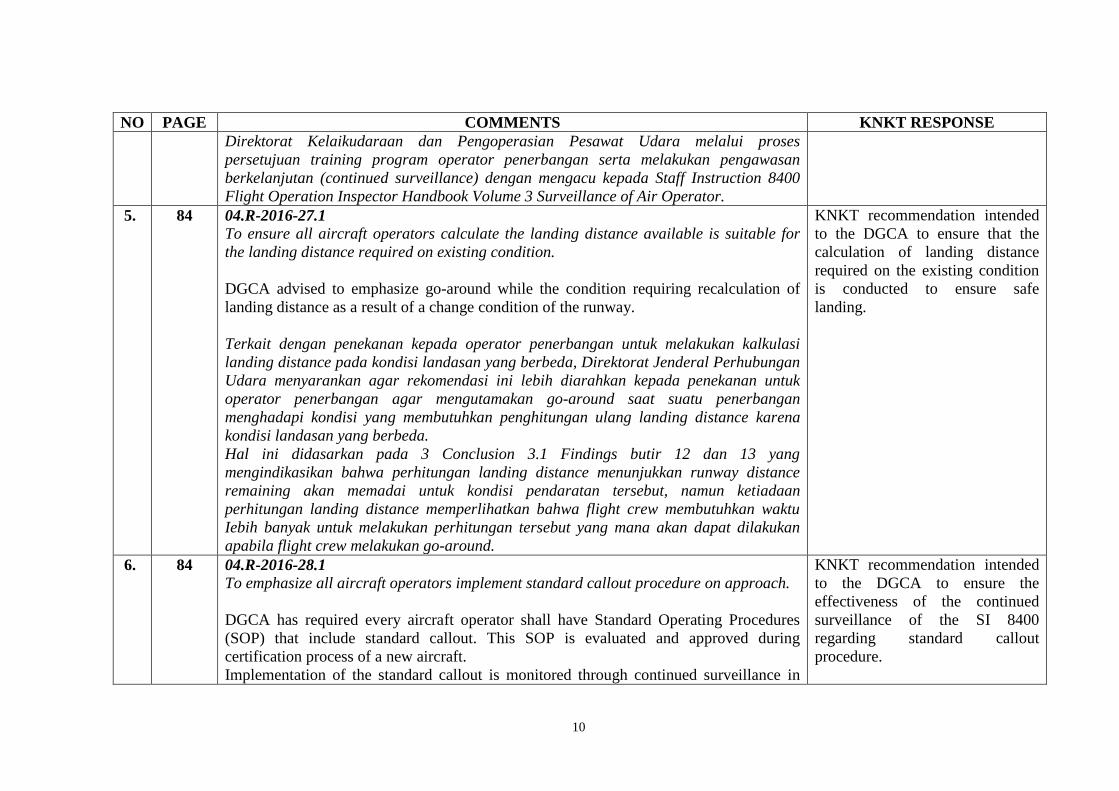
10
NO PAGE COMMENTS KNKT RESPONSE
Direktorat Kelaikudaraan dan Pengoperasian Pesawat Udara melalui proses
persetujuan training program operator penerbangan serta melakukan pengawasan
berkelanjutan (continued surveillance) dengan mengacu kepada Staff Instruction 8400
Flight Operation Inspector Handbook Volume 3 Surveillance of Air Operator.
5. 84 04.R-2016-27.1
To ensure all aircraft operators calculate the landing distance available is suitable for
the landing distance required on existing condition.
DGCA advised to emphasize go-around while the condition requiring recalculation of
landing distance as a result of a change condition of the runway.
Terkait dengan penekanan kepada operator penerbangan untuk melakukan kalkulasi
landing distance pada kondisi landasan yang berbeda, Direktorat Jenderal Perhubungan
Udara menyarankan agar rekomendasi ini lebih diarahkan kepada penekanan untuk
operator penerbangan agar mengutamakan go-around saat suatu penerbangan
menghadapi kondisi yang membutuhkan penghitungan ulang landing distance karena
kondisi landasan yang berbeda.
Hal ini didasarkan pada 3 Conclusion 3.1 Findings butir 12 dan 13 yang
mengindikasikan bahwa perhitungan landing distance menunjukkan runway distance
remaining akan memadai untuk kondisi pendaratan tersebut, namun ketiadaan
perhitungan landing distance memperlihatkan bahwa flight crew membutuhkan waktu
Iebih banyak untuk melakukan perhitungan tersebut yang mana akan dapat dilakukan
apabila flight crew melakukan go-around.
KNKT recommendation intended
to the DGCA to ensure that the
calculation of landing distance
required on the existing condition
is conducted to ensure safe
landing.
6. 84 04.R-2016-28.1
To emphasize all aircraft operators implement standard callout procedure on approach.
DGCA has required every aircraft operator shall have Standard Operating Procedures
(SOP) that include standard callout. This SOP is evaluated and approved during
certification process of a new aircraft.
Implementation of the standard callout is monitored through continued surveillance in
KNKT recommendation intended
to the DGCA to ensure the
effectiveness of the continued
surveillance of the SI 8400
regarding standard callout
procedure.
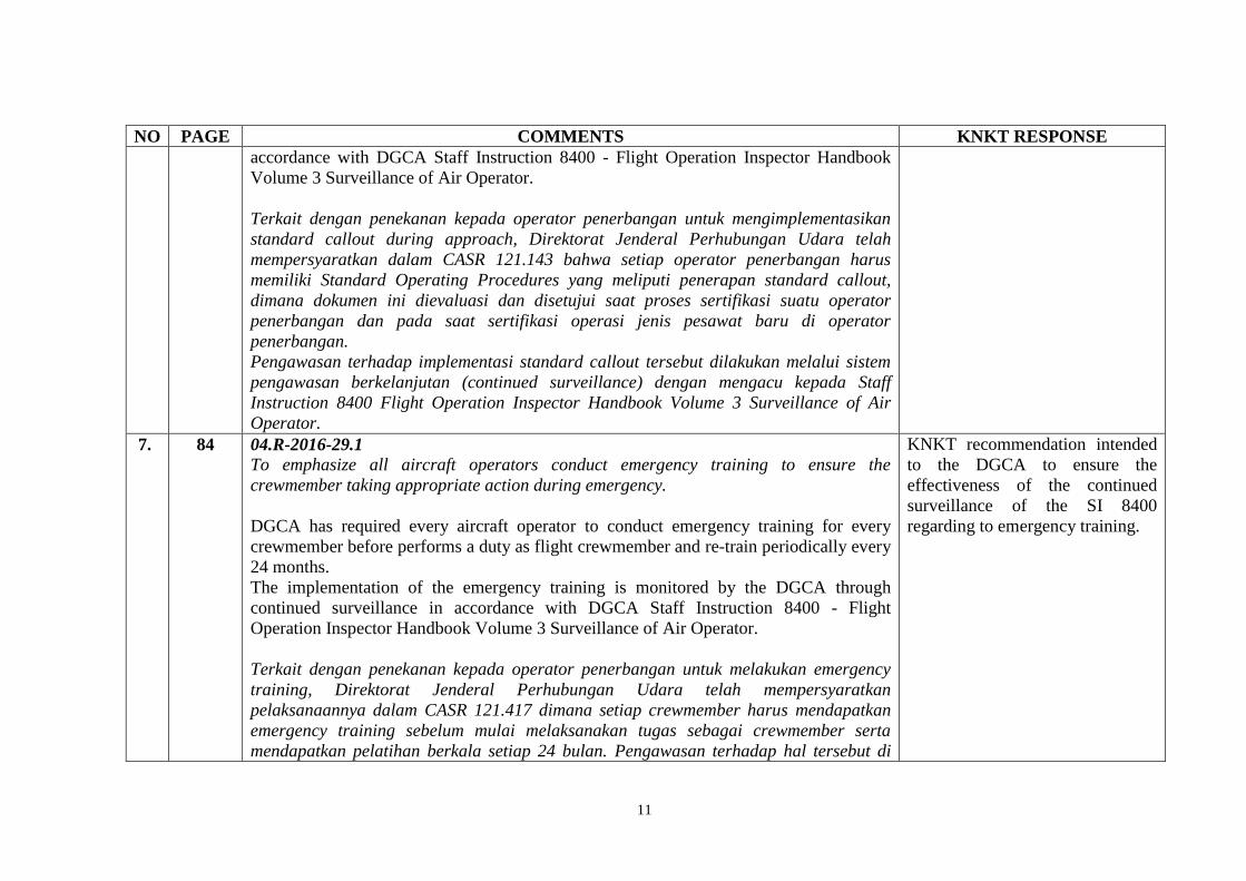
11
NO PAGE COMMENTS KNKT RESPONSE
accordance with DGCA Staff Instruction 8400 - Flight Operation Inspector Handbook
Volume 3 Surveillance of Air Operator.
Terkait dengan penekanan kepada operator penerbangan untuk mengimplementasikan
standard callout during approach, Direktorat Jenderal Perhubungan Udara telah
mempersyaratkan dalam CASR 121.143 bahwa setiap operator penerbangan harus
memiliki Standard Operating Procedures yang meliputi penerapan standard callout,
dimana dokumen ini dievaluasi dan disetujui saat proses sertifikasi suatu operator
penerbangan dan pada saat sertifikasi operasi jenis pesawat baru di operator
penerbangan.
Pengawasan terhadap implementasi standard callout tersebut dilakukan melalui sistem
pengawasan berkelanjutan (continued surveillance) dengan mengacu kepada Staff
Instruction 8400 Flight Operation Inspector Handbook Volume 3 Surveillance of Air
Operator.
7. 84 04.R-2016-29.1
To emphasize all aircraft operators conduct emergency training to ensure the
crewmember taking appropriate action during emergency.
DGCA has required every aircraft operator to conduct emergency training for every
crewmember before performs a duty as flight crewmember and re-train periodically every
24 months.
The implementation of the emergency training is monitored by the DGCA through
continued surveillance in accordance with DGCA Staff Instruction 8400 - Flight
Operation Inspector Handbook Volume 3 Surveillance of Air Operator.
Terkait dengan penekanan kepada operator penerbangan untuk melakukan emergency
training, Direktorat Jenderal Perhubungan Udara telah mempersyaratkan
pelaksanaannya dalam CASR 121.417 dimana setiap crewmember harus mendapatkan
emergency training sebelum mulai melaksanakan tugas sebagai crewmember serta
mendapatkan pelatihan berkala setiap 24 bulan. Pengawasan terhadap hal tersebut di
KNKT recommendation intended
to the DGCA to ensure the
effectiveness of the continued
surveillance of the SI 8400
regarding to emergency training.
12
NO PAGE COMMENTS KNKT RESPONSE
atas dilakukan melalui sistem pengawasan berkelanjutan (continued surveillance)
dengan mengacu kepada Staff Instruction 8400 Flight Operation Inspector Handbook
Volume 3 Surveillance of Air Operator.