kr-35h-v rough terrain crane (power jib) - titan cranes ss-350 sp-v kr-35h-v2 rough terrain crane...
TRANSCRIPT

K R -35H-V 2 R ough T errain Crane (Power Jib) SPECIFICA TION
Crane Specification Crane Performance
9.60m B oom 35.0 T onne @ 3.0m (10 Parts of L ine) 16.25m B oom 22.5 T onne @ 4.0m (6 Parts of L ine) 22.90m B oom 15.5 T onne @ 5.0m (6 Parts of L ine) 29.55m B oom 10.0 T onne @ 7.0m (4 Parts of L ine) 36.20m B oom 7.0 T onne @ 8.0m (4 Parts of L ine) 8.0m Jib 3.4 T onne @ 78° (1 Part of L ine) 13.20m Jib 2.2 T onne @ 77° (1 Part of L ine)
R ated L ifting Capacity
R ooster Sheave 4.0 T onne (1 Part of L ine) B oom L ength 9.6m - 36.2m Jib L ength 8.0m - 13.2m
37.1m (B oom) Maximum L ifting Height Above Ground 50.9m (Jib) L ine Speed (Main) 118m/min (4th layer) L ine Speed (Auxiliary) 107m/min (3rd layer) Hook Speed (Main) (Parts of L ine 10) 11.8m/min (4th layer) Hook Speed (Auxiliary) (Parts of L ine 1) 107m/min (2nd layer) B oom Derricking R ange 0° ~ 83° B oom R aising Speed 0° ~ 83°/58 sec B oom E xtension Speed 9.6m ~ 36.2m/115 sec Slewing Speed 2.5 rpm R ear Slewing R adius 3,240 mm Crane Equipment and Structure Hoist E quipment Group 2 Single W inch, 2-Stage Speed R eduction T ype Hydraulic Motor Drive /
Spur Gear R educer / Automatic B rake T ype (with Foot B rake, Freefall Device), Flow R egulator with Pressure Compensator
Slewing E quipment Free L ock Change Switch with Hydraulic Motor Drive / Planetary Gear Speed R educer (Negative B rake E mbedded)
Slew Circle B all B earing T ype B oom Derricking Equipment Direct Press Hydraulic Cylinder T ype, Flow R egulator with Pressure CompensatorB oom E xtension E quipment Hydraulic Cylinder (2) with W ire R ope
T ype Fully Hydraulic H T ype (Float, V ertical Cylinder Model) Outrigger E quipment E xtension
R ange 6,800 mm (Full E xtension) 6,200 mm (Intermediate E xtension) 5,300 mm (Intermediate E xtension) 3,900 mm (Intermediate E xtension) 2,340 mm (Full R etraction)
Main SeS(48) + 6 × WS(31) ø 16 mm × 195m W ire R ope Auxiliary IWR C 6 × Fi(29) ø 16 mm × 105m
Hydraulic Equipment Oil Pump Double High Pressure V ariable Plunger T ype, Gear + Plunger T ype Hydraulic Motor Hoisting and Slewing: Axial Plunger T ype Control V alve Multiple Auto R ecovery T ype (with Pressure Compensator, Flow R egulator) Cylinder Double A cting T ype Oil R eservoir 525L Safety Equipment ACS (with Overload Protector/V oice Alarm Device), Slewing A utomatic Stop
Device, B oom Derricking and B oom E xtension Stop Device, Swing Clearance R estriction Device, Outrigger E xtension R ange Auto Detection Unit, B oom Freefall Prevention Device, Overhoist Prevention Device, Drum L ock Device, Drum Hold Safety Device, Automatic B rake Device, Hoist Jam Prevention Device,Hydraulic Safety V alve, Outrigger L ock Device, Slewing W arning L ight, Hyd. Fluid Overheat Alarm Device, Operating Oil Filter Clog Warning Device
www.titancranes.co.nz Phone: 0800 848 262
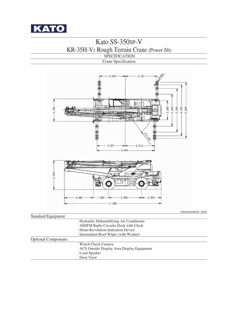
Kato SS-350SP-V KR-35H-V2 Rough Terrain Crane (Power Jib)
SPECIFICATION Crane Specification
(measurement: mm)
Standard Equipment
Hydraulic Dehumidifying Air Conditioner AM/FM Radio Cassette Deck with Clock Drum Revolution Indication Device Intermittent Roof Wiper (with Washer)
Optional Components
Winch Check Camera ACS Outside Display Area Display Equipment Loud Speaker Door Visor

Kato SS-350SP-V KR-35H-V2 Rough Terrain Crane (Power Jib)
SPECIFICATION Carrier Specification
Driving Performance Maximum Travelling Speed 49 km/hr Uphill Ability 0.60 (tan θ)
8.4m (2 Wheel Steering) Minimum Turning Radius 5.3m (4 Wheel Steering)
Weight and Dimensions Overall Length 11,580 mm approx. Overall Width 2,750 mm approx. Overall Height 3,550 mm approx. Distance Between Axles 3,900 mm approx.
Front 2,230 mm Treads Rear 2,230 mm
Seats 1 Gross Vehicle Weight Overall Weight 32,595 kg approx. Front Axle Weight 16,260 kg approx. Rear Axle Weight 16,335 kg approx. Engine Engine Model Mitsubishi 6D24-TE I (with Turbo) Engine Type 6 Cylinder, Water Cooled 4 Cycle, Direct Injection Type Diesel Engine Total Emission 11.945L Maximum Power 290ps/2,200 rpm Maximum Torque 100kg-m/1,400 rpm Carrier Components and Structure Drive System Full-Time 4 Wheel Drive (4×4) Torque Converter 3 Components, 1 Stage (with Automatic Lock Up Clutch) Transmission Type Automatic and Manual Gear Transmission Type (with transfer differential) Number of Gears 6 Forward Gears, 2 Reverse Gears Axle Type Front and Rear: Full Floating Type Fuel Tank Capacity 300L Main Brake Dual System Combined Hydraulic Pneumatic Type, 4 Wheel Disc Brakes
(Double Calliper) Park Brake Mechanical Type, Transmission Braking Internal Expansion Type Auxiliary Brake Exhaust Brake (torque lock-up simultaneous control system through the electric
controls), Auxiliary Braking Device for Operation Front Hydro-Pneumatic Suspension (with Hydraulic Lock Cylinder Type) Suspension
Components Rear Hydro-Pneumatic Suspension (with Hydraulic Lock Cylinder Type) Steering Type Complete Hydraulic Type Power Steering with Opposite Steering Correction
Device Steering Mode Front 2 Wheels, Crab Counter, Independent Front/Rear Wheels (5 Modes),
(with Rear Steering Automatic Lock Mechanism) Front 445/95 R25 177E ROAD Tyre Size Rear 445/95 R25 177E ROAD
Safety Components
Emergency Steering Device, Rear Wheel Steering Lock Device, Miss-shift Prevention Device, Brake Fluid Leakage Alarm Device, Suspension Lock Device, Auxiliary Braking Device for Operation, Overrun Alarm Device, Electrically Housable Side Mirrors, Mirror Right Side of the Boom (with Heater), Radiator Fluid Level Alarm Device, Operating Oil Filter Clog Warning Device
Optional Devices Rear Check Camera, Boom Left Hand Side Check Mirrors

Rated Lifting Capacity Table (1)
9.6m ~ 36.2m Boom
Outriggers Fully Extended (6.8m) - 360° Full Range
Outriggers Intermediately Extended (6.2m) - Over Side
Working Radius
(m) 9.6m Boom
16.25m Boom
22.9m Boom
29.55m Boom
36.2m Boom
9.6m Boom
16.25m Boom
22.9m Boom
29.55mBoom
36.2m Boom
3.0 35.00 22.50 15.50 10.00 35.00 22.50 15.50 10.00 3.5 30.60 22.50 15.50 10.00 7.00 30.60 22.50 15.50 10.00 7.00 4.0 27.50 22.50 15.50 10.00 7.00 27.50 22.50 15.50 10.00 7.00 4.5 24.70 20.70 15.50 10.00 7.00 24.70 20.70 15.50 10.00 7.00 5.0 22.50 19.30 15.50 10.00 7.00 22.50 19.30 15.50 10.00 7.00 5.5 20.60 17.90 14.40 10.00 7.00 20.60 17.90 14.40 10.00 7.00 6.0 19.10 16.80 13.45 10.00 7.00 19.10 16.80 13.45 10.00 7.00 6.5 16.70 15.80 12.55 10.00 7.00 16.70 15.80 12.55 10.00 7.00 7.0 13.00 14.90 11.85 10.00 7.00 13.00 14.90 11.85 10.00 7.00 8.0 13.10 10.60 9.00 7.00 12.40 10.60 9.00 7.00 9.0 11.20 9.60 8.05 6.40 9.70 9.60 8.05 6.40 10.0 9.45 8.60 7.25 5.80 7.90 8.60 7.25 5.80 11.0 7.80 7.80 6.60 5.30 6.40 7.30 6.60 5.30 12.0 6.50 7.05 6.05 4.90 5.30 6.15 6.05 4.90 13.0 5.50 6.30 5.55 4.50 4.40 5.20 5.55 4.50 14.0 5.45 5.10 4.15 4.50 4.80 4.15 15.0 4.70 4.70 3.85 3.90 4.30 3.85 16.0 4.10 4.35 3.60 3.35 3.80 3.60 17.0 3.60 4.05 3.35 2.90 3.35 3.35 18.0 3.10 3.60 3.15 2.45 2.95 3.10 19.0 2.70 3.15 2.95 2.10 2.55 2.75 20.0 2.30 2.80 2.75 1.75 2.25 2.45 22.0 2.15 2.40 1.65 1.95 24.0 1.60 1.85 1.20 1.45 26.0 1.20 1.45 0.80 1.05 28.0 1.05 0.70 30.0 0.75 0.45 32.0 0.50 33.0 0.40
Critical Boom Angle
- - - - - - - - - 20°
Standard Hook 35t 22.5t 35t 22.5t Hook Weight 290 kg 220 kg 290 kg 220 kg Parts of Line 10 6 6 4 4 10 6 6 4 4
(unit: metric ton)

Rated Lifting Capacity Table (1)
9.6m ~ 36.2m Boom
Outriggers Intermediately Extended (5.3m) - Over Side
Outriggers Intermediately Extended (3.9m) - Over Side
Working Radius
(m) 9.6m Boom
16.25m Boom
22.9m Boom
29.55m Boom
36.2m Boom
9.6m Boom
16.25m Boom
22.9m Boom
29.55mBoom
36.2m Boom
3.0 35.00 22.50 15.50 10.00 35.00 22.50 15.50 10.00 3.5 30.60 22.50 15.50 10.00 7.00 30.00 22.50 15.50 10.00 7.00 4.0 27.50 22.50 15.50 10.00 7.00 22.20 20.60 15.50 10.00 7.00 4.5 24.70 20.70 15.50 10.00 7.00 17.40 16.60 15.50 10.00 7.00 5.0 22.50 19.30 15.50 10.00 7.00 14.15 13.40 13.90 10.00 7.00 5.5 20.60 17.90 14.40 10.00 7.00 11.80 11.10 12.00 10.00 7.00 6.0 17.50 16.65 13.45 10.00 7.00 10.00 9.35 10.30 10.00 7.00 6.5 14.90 14.05 12.55 10.00 7.00 8.60 8.00 8.90 9.00 7.00 7.0 12.85 12.10 11.85 10.00 7.00 7.50 6.90 7.75 8.10 7.00 8.0 9.25 10.00 9.00 7.00 5.25 6.00 6.50 6.65 9.0 7.25 8.10 8.05 6.40 4.05 4.80 5.25 5.50 10.0 5.85 6.65 6.95 5.80 3.15 3.85 4.30 4.55 11.0 4.75 5.50 6.00 5.30 2.45 3.15 3.55 3.80 12.0 3.90 4.65 5.10 4.90 1.75 2.55 2.95 3.20 13.0 3.20 3.90 4.35 4.50 1.20 2.10 2.50 2.70 14.0 3.35 3.75 3.90 1.60 2.10 2.30 15.0 2.85 3.25 3.45 1.20 1.70 1.95 16.0 2.40 2.80 3.05 0.85 1.35 1.60 17.0 1.95 2.45 2.65 0.55 1.00 1.30 18.0 1.60 2.10 2.35 0.75 1.00 19.0 1.25 1.75 2.00 0.50 0.75 20.0 1.00 1.45 1.70 22.0 0.95 1.20 24.0 0.55 0.80 26.0 0.50 28.0 30.0 32.0 33.0
Critical Boom Angle
- - - 20° 35° - - 25° 43° 53°
Standard Hook 35t 22.5t 35t 22.5t Hook Weight 290 kg 220 kg 290 kg 220 kg Parts of Line 10 6 6 4 4 10 6 6 4 4
(unit: metric ton)
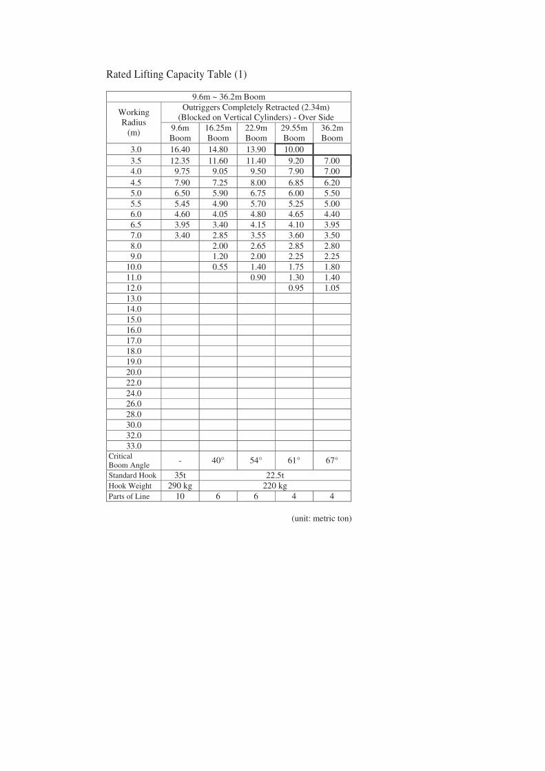
Rated Lifting Capacity Table (1)
9.6m ~ 36.2m Boom
Outriggers Completely Retracted (2.34m) (Blocked on Vertical Cylinders) - Over Side
Working Radius
(m) 9.6m Boom
16.25m Boom
22.9m Boom
29.55m Boom
36.2m Boom
3.0 16.40 14.80 13.90 10.00 3.5 12.35 11.60 11.40 9.20 7.00 4.0 9.75 9.05 9.50 7.90 7.00 4.5 7.90 7.25 8.00 6.85 6.20 5.0 6.50 5.90 6.75 6.00 5.50 5.5 5.45 4.90 5.70 5.25 5.00 6.0 4.60 4.05 4.80 4.65 4.40 6.5 3.95 3.40 4.15 4.10 3.95 7.0 3.40 2.85 3.55 3.60 3.50 8.0 2.00 2.65 2.85 2.80 9.0 1.20 2.00 2.25 2.25 10.0 0.55 1.40 1.75 1.80 11.0 0.90 1.30 1.40 12.0 0.95 1.05 13.0 14.0 15.0 16.0 17.0 18.0 19.0 20.0 22.0 24.0 26.0 28.0 30.0 32.0 33.0
Critical Boom Angle
- 40° 54° 61° 67°
Standard Hook 35t 22.5t Hook Weight 290 kg 220 kg Parts of Line 10 6 6 4 4
(unit: metric ton)

Rated Lifting Capacity Table (2)
36.2m Boom + 8.0m Jib
Outriggers Fully Extended (6.8m) - 360° Full Range 5° Offset 25° Offset 45° Offset Boom
Angle (°)
Working Radius (m)
Load (t)
Working Radius (m)
Load (t)
Working Radius (m)
Load (t)
83.0 5.2 3.40 7.8 2.10 9.9 1.60 78.0 9.5 3.40 11.8 2.10 13.6 1.60 77.0 10.3 3.32 12.6 2.10 14.3 1.60 75.0 11.9 2.96 14.0 1.98 15.8 1.50 70.0 15.7 2.30 17.7 1.66 19.2 1.35 65.0 19.2 1.87 21.0 1.44 22.3 1.21 60.0 22.5 1.58 24.2 1.26 25.2 1.10 56.0 25.0 1.40 26.6 1.14 27.4 1.03 54.0 26.2 1.34 27.8 1.08 28.5 1.00 52.0 27.3 1.12 28.8 1.04 29.5 0.97 50.0 28.3 0.92 29.8 0.85 30.4 0.82 47.0 29.9 0.67 31.2 0.62 31.6 0.62 43.0 31.8 0.40 32.9 0.38
Critical Boom Angle
40° 40° 45°
Standard Hook 4.0t Hook Weight 60 kg Parts of Line 1
(unit: metric ton)
36.2m Boom + 8.0m Jib
Outriggers Intermediately Extended (6.2m) - Over Side 5° Offset 25° Offset 45° Offset Boom
Angle (°)
Working Radius (m)
Load (t)
Working Radius (m)
Load (t)
Working Radius (m)
Load (t)
83.0 5.2 3.40 7.8 2.10 9.9 1.60 78.0 9.5 3.40 11.8 2.10 13.6 1.60 77.0 10.3 3.32 12.6 2.10 14.3 1.60 75.0 11.9 2.96 14.0 1.98 15.8 1.50 70.0 15.7 2.30 17.7 1.66 19.2 1.35 65.0 19.2 1.87 21.0 1.44 22.3 1.21 60.0 22.5 1.58 24.2 1.26 25.2 1.10 56.0 25.0 1.20 26.6 1.08 27.4 1.03 52.0 27.3 0.75 28.8 0.70 29.3 0.70 50.0 28.3 0.58 29.8 0.54 30.3 0.54 48.0 29.4 0.42 30.7 0.41 31.2 0.40
Critical Boom Angle
46° 46° 46°
Standard Hook 4.0t Hook Weight 60 kg Parts of Line 1
(unit: metric ton)
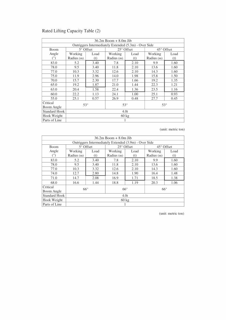
Rated Lifting Capacity Table (2)
36.2m Boom + 8.0m Jib
Outriggers Intermediately Extended (5.3m) - Over Side 5° Offset 25° Offset 45° Offset Boom
Angle (°)
Working Radius (m)
Load (t)
Working Radius (m)
Load (t)
Working Radius (m)
Load (t)
83.0 5.2 3.40 7.8 2.10 9.9 1.60 78.0 9.5 3.40 11.8 2.10 13.6 1.60 77.0 10.3 3.32 12.6 2.10 14.3 1.60 75.0 11.9 2.96 14.0 1.98 15.8 1.50 70.0 15.7 2.30 17.7 1.66 19.2 1.35 65.0 19.2 1.87 21.0 1.44 22.3 1.21 63.0 20.4 1.58 22.4 1.36 23.5 1.16 60.0 22.2 1.13 24.1 1.00 25.1 0.93 55.0 25.1 0.57 26.9 0.48 27.7 0.45
Critical Boom Angle
53° 53° 53°
Standard Hook 4.0t Hook Weight 60 kg Parts of Line 1
(unit: metric ton)
36.2m Boom + 8.0m Jib Outriggers Intermediately Extended (3.9m) - Over Side
5° Offset 25° Offset 45° Offset Boom Angle
(°) Working
Radius (m) Load
(t) Working
Radius (m) Load
(t) Working
Radius (m) Load
(t) 83.0 5.2 3.40 7.8 2.10 9.9 1.60 78.0 9.5 3.40 11.8 2.10 13.6 1.60 77.0 10.3 3.32 12.6 2.10 14.3 1.60 74.0 12.7 2.80 14.8 1.90 16.4 1.48 71.0 14.7 2.08 16.9 1.71 18.5 1.38 68.0 16.6 1.44 18.8 1.19 20.3 1.06
Critical Boom Angle
66° 66° 66°
Standard Hook 4.0t Hook Weight 60 kg Parts of Line 1
(unit: metric ton)

Rated Lifting Capacity Table (3)
36.2m Boom + 13.2m Jib
Outriggers Fully Extended (6.8m) - 360° Full Range 5° Offset 25° Offset 45° Offset Boom
Angle (°)
Working Radius (m)
Load (t)
Working Radius (m)
Load (t)
Working Radius (m)
Load (t)
83.0 6.5 2.20 10.8 1.25 14.2 0.90 78.0 11.3 2.20 15.4 1.25 18.1 0.90 77.0 12.3 2.20 16.2 1.24 18.9 0.86 75.0 14.0 1.99 17.8 1.17 20.3 0.82 70.0 18.2 1.55 21.6 1.02 23.9 0.76 65.0 22.1 1.25 25.3 0.89 27.2 0.70 60.0 25.8 1.04 28.8 0.78 30.2 0.66 55.0 29.3 0.89 32.0 0.69 33.1 0.61 52.0 31.3 0.82 33.7 0.65 34.6 0.59 50.0 32.4 0.72 34.9 0.62 35.6 0.57 47.0 34.1 0.51 36.3 0.45 36.9 0.45 45.0 35.2 0.39 37.2 0.35
Critical Boom Angle
43° 43° 45°
Standard Hook 4.0t Hook Weight 60 kg Parts of Line 1
(unit: metric ton)
36.2m Boom + 13.2m Jib Outriggers Intermediately Extended (6.2m) - Over Side
5° Offset 25° Offset 45° Offset Boom Angle
(°) Working
Radius (m) Load
(t) Working
Radius (m) Load
(t) Working
Radius (m) Load
(t) 83.0 6.5 2.20 10.8 1.25 14.2 0.90 78.0 11.3 2.20 15.4 1.25 18.1 0.90 77.0 12.3 2.20 16.2 1.24 18.9 0.86 75.0 14.0 1.99 17.8 1.17 20.3 0.82 70.0 18.2 1.55 21.6 1.02 23.9 0.76 65.0 22.1 1.25 25.3 0.89 27.2 0.70 60.0 25.8 1.04 28.8 0.78 30.2 0.66 55.0 29.3 0.81 31.9 0.69 33.1 0.61 52.0 31.3 0.57 33.5 0.54 34.6 0.52 50.0 32.4 0.43 34.6 0.40 35.6 0.39
Critical Boom Angle
48° 48° 48°
Standard Hook 4.0t Hook Weight 60 kg Parts of Line 1
(unit: metric ton)

Rated Lifting Capacity Table (3)
36.2m Boom + 13.2m Jib
Outriggers Intermediately Extended (5.3m) - Over Side 5° Offset 25° Offset 45° Offset Boom
Angle (°)
Working Radius (m)
Load (t)
Working Radius (m)
Load (t)
Working Radius (m)
Load (t)
83.0 6.5 2.20 10.8 1.25 14.2 0.90 78.0 11.3 2.20 15.4 1.25 18.1 0.90 77.0 12.3 2.20 16.2 1.24 18.9 0.86 75.0 14.0 1.99 17.8 1.17 20.3 0.82 70.0 18.2 1.55 21.6 1.02 23.9 0.76 65.0 22.1 1.25 25.3 0.89 27.2 0.70 63.0 23.7 1.15 26.7 0.84 28.4 0.69 61.0 25.0 1.00 28.1 0.80 29.7 0.67 56.0 28.2 0.48 31.0 0.40 32.4 0.37
Critical Boom Angle
54° 54° 54°
Standard Hook 4.0t Hook Weight 60 kg Parts of Line 1
(unit: metric ton)
36.2m Boom + 13.2m Jib
Outriggers Intermediately Extended (3.9m) - Over Side 5° Offset 25° Offset 45° Offset Boom
Angle (°)
Working Radius (m)
Load (t)
Working Radius (m)
Load (t)
Working Radius (m)
Load (t)
83.0 6.5 2.20 10.8 1.25 14.2 0.90 78.0 11.3 2.20 15.4 1.25 18.1 0.90 77.0 12.3 2.20 16.2 1.24 18.9 0.86 75.0 14.0 1.99 17.8 1.17 20.3 0.82 72.0 16.5 1.71 20.1 1.07 22.5 0.78 70.0 18.0 1.46 21.6 1.02 23.9 0.76 68.0 19.5 1.08 23.0 0.85 25.2 0.70
Critical Boom Angle
66° 66° 66°
Standard Hook 4.0t Hook Weight 60 kg Parts of Line 1
(unit: metric ton)
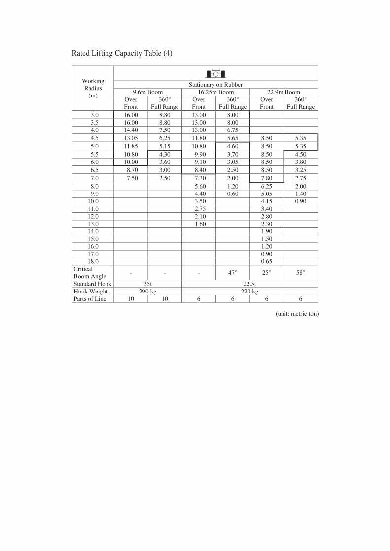
Rated Lifting Capacity Table (4)
Stationary on Rubber 9.6m Boom 16.25m Boom 22.9m Boom
Working Radius
(m) Over Front
360° Full Range
Over Front
360° Full Range
Over Front
360° Full Range
3.0 16.00 8.80 13.00 8.00 3.5 16.00 8.80 13.00 8.00 4.0 14.40 7.50 13.00 6.75 4.5 13.05 6.25 11.80 5.65 8.50 5.35 5.0 11.85 5.15 10.80 4.60 8.50 5.35 5.5 10.80 4.30 9.90 3.70 8.50 4.50 6.0 10.00 3.60 9.10 3.05 8.50 3.80 6.5 8.70 3.00 8.40 2.50 8.50 3.25 7.0 7.50 2.50 7.30 2.00 7.80 2.75 8.0 5.60 1.20 6.25 2.00 9.0 4.40 0.60 5.05 1.40 10.0 3.50 4.15 0.90 11.0 2.75 3.40 12.0 2.10 2.80 13.0 1.60 2.30 14.0 1.90 15.0 1.50 16.0 1.20 17.0 0.90 18.0 0.65
Critical Boom Angle
- - - 47° 25° 58°
Standard Hook 35t 22.5t Hook Weight 290 kg 220 kg Parts of Line 10 10 6 6 6 6
(unit: metric ton)

Rated Lifting Capacity Table (4)
Pick & Carry (Travelling Speed Maximum 2 km/h) 9.6m Boom 16.25m Boom 22.9m Boom
Working Radius
(m) Over Front
360° Full Range
Over Front
360° Full Range
Over Front
360° Full Range
3.0 12.00 6.60 10.00 6.00 3.5 12.00 6.60 10.00 6.00 4.0 10.80 5.55 10.00 5.05 4.5 9.75 4.70 9.15 4.20 7.50 4.00 5.0 8.90 4.00 8.35 3.45 7.50 4.00 5.5 8.15 3.35 7.60 2.80 7.50 3.40 6.0 7.30 2.80 6.95 2.30 6.90 2.85 6.5 6.60 2.35 6.10 1.85 6.35 2.40 7.0 5.90 1.90 5.35 1.45 5.85 2.05 8.0 4.10 0.80 4.65 1.40 9.0 3.20 3.75 0.90 10.0 2.55 3.05 11.0 2.00 2.50 12.0 1.50 2.05 13.0 1.10 1.65 14.0 1.35 15.0 1.10 16.0 0.85 17.0 0.60
Critical Boom Angle
- - - 50° 35° 60°
Standard Hook 35t 22.5t Hook Weight 290 kg 220 kg Parts of Line 10 10 6 6 6 6
(unit: metric ton)

Notes for the Rated Lifting Capacity Chart
Rated Lifting Capacity Chart (1) (2) When Using Outriggers
1. The rated lifting capacities are the maximum load guaranteed on firm level ground with the crane set horizontal and includes the weight of the hook block and other lifting equipment. The capacities enclosed in bold lines are based on the structural strength of the machine and the other values are based on the stability of the machine.
2. The operating radii as given in the table are the actual values including the deflection
of the boom. Therefore operate the crane based on the operating radius. 3. The operating radii shown for jib operations are based on the values obtained when
the jib is attached to the 36.2m boom (full extension). When the boom is not fully extended (28.0m) the jib operations should be performed on the basis of boom angle and not on the operating radius.
4. Do not perform jib operations with the outriggers in the minimum extended state. 5. The lifting capacity for the respective operating ranges will differ according to the
outrigger extension. In general, operate the crane with the outriggers fully extended for safe operation. If you cannot extend the outriggers fully due to obstacles that cannot be removed, obtain approval from the site manager then check the crane capacity for the respective operating ranges on the rated lifting capacity charts provided.
Outrigger Extension Status
Intermediately Extended (6.2m)
Intermediately Extended (5.3m)
Intermediately Extended (3.9m)
Fully Retracted
Range a° 35 30 20 3
6. When the boom length is 9.6m the rated lifting capacities for the rooster sheave are
equivalent to the rated lifting capacity for the boom minus the weight (290 kg) of the 35 ton hook and have a limit of 4,000 kg. When the boom length is above 9.6m and up to 36.2m, the rated lifting capacities for the rooster sheave are equivalent to the rated lifting capacity for the boom minus the weight (220 kg) of the 22.5 ton hook and have a limit of 4,000 kg. [Rooster sheave hook: 4 ton hook (weight 60 kg), 1 line].
7. When the boom length exceeds specified length operate according to the smaller rated lifting capacity out of the specified length or the boom length one level up.
8. When using the boom with the jib installed the rated lifting capacities are equivalent
to the rated lifting capacity of the boom when the outrigger extension within 6.8m, 6.2m or 5.3m minus the weight of 2.2 ton and minus the weight of 3.0 ton when the outrigger extension is 3.9m.
When the jib is installed do not operate the rooster sheave and when the outriggers are in the minimum extended state and the jib is installed, do not operate the boom.
Front Area Rear Area
Notes for the Rated Lifting Capacity Chart
Rated Lifting Capacity Chart (1) (2) When Using Outriggers
9. The critical boom angles for each operation status are shown on the rated lifting
capacity charts. If the boom angle is lowered to less than the critical boom angle the crane will tip over even without a load.
10. The standard number of parts of line relating to each boom length is shown in the
rated lifting capacity charts. When the standard number of parts of line is not used, each wire rope is limited to 37.3kN (3.8tf).
11. When using the jib if the jib offset angle exceeds the specified angle operations
should be based on the rated lifting capacity for the jib offset angle that is one larger than the specified angle.
12. In general, free fall is used to lower the hook only. If it is necessary to lower a load
by free fall, its weight should be less than 20% of the rated lifting capacity and sudden braking should not be allowed.
13. The rated lifting capacity chart when the outriggers are in the minimum extended
state applies to only the crane with the H type outrigger. 14. The rated lifting capacities do not include wind interference. Stop the operation
when a peak of wind speed is 10m/sec above. 15. The crane will tip over or be damaged if operated with a load exceeding that
specified in the rated lifting capacity chart or not conforming to correct handling. Insurance will not cover any damage that occurs in these situations.

Notes for the Rated Lifting Capacity Chart
Rated Lifting Capacity Chart (3) When Not Using Outriggers 1. The rated lifting capacities are the maximum loads guaranteed on firm level ground
with the tyres at the specified pressure and the suspension lock cylinders fully retracted. They include the weight of the hook and the lifting equipment.
The capacities enclosed in bold lines are based on the structural strength of the machine and the other values are based on the stability of the machine.
[Tyre air pressure: 900kPa (9.0 kgf/cm2)] 2. Rated lifting capacities in the front area differ from those for the full working area.
Great care should be taken when transferring from over front to over side as there is a danger of overloading.
Crane Operation Stationary Lifting Mobiling Range a° 1 1
3. Do not carry out any boom operations, jib operations and free fall operation with the
boom length exceeding 22.9m. 4. Apply the parking brake and brake lock when performing stationary lifting. 5. For mobiling place the shift lever in 1st and turn the ultra-low speed switch ON. 6. It is very dangerous for the load to swing while mobiling. Therefore hold the load
just off the ground so that it can be lowered onto the ground immediately if you sense any danger and travel at less than 2 km/h. Avoid abrupt acceleration, cornering and braking.
7. Never perform crane operations while mobiling. Also apply the slewing brake. 8. As well as the above items, perform operations according to caution items 2, 6, 7, 9,
10, 14, 15 for when using outriggers.
Front Area a°a°

Working Range Diagram
Working Radius (m)
Caution 1. The diagram above does not allow for boom and jib deflections. 2. The chart above is based on operation with all outriggers at full extension.
Height above ground (m
)
36.2m Boom + 13.2m Jib (offset 5°) 36.2m Boom + 13.2m Jib (offset 25°)
36.2m Boom + 13.25m Jib (offset 45°)
36.2m Boom + 8.0m Jib (offset 5°)
36.2m Boom + 8.0m Jib (offset 25°)
36.2m Boom + 8.0m Jib (offset 45°)
36.2m Boom 29.55m Boom
22.9m Boom
16.25m Boom
9.6m Boom
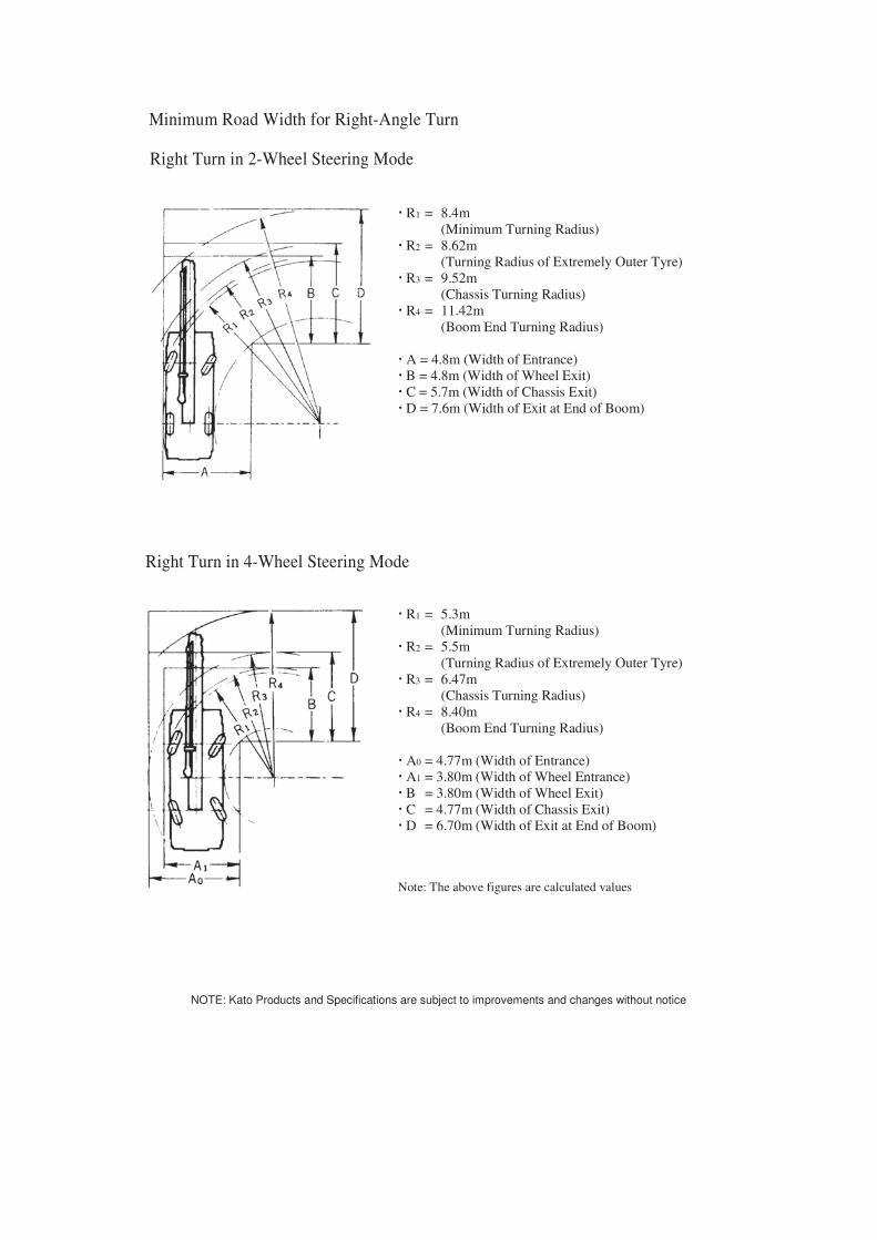
Minimum Road Width for Right-Angle Turn
Right Turn in 2-Wheel Steering Mode
R1 = 8.4m
(Minimum Turning Radius) R2 = 8.62m
(Turning Radius of Extremely Outer Tyre) R3 = 9.52m
(Chassis Turning Radius) R4 = 11.42m
(Boom End Turning Radius) A = 4.8m (Width of Entrance) B = 4.8m (Width of Wheel Exit) C = 5.7m (Width of Chassis Exit) D = 7.6m (Width of Exit at End of Boom)
Right Turn in 4-Wheel Steering Mode
R1 = 5.3m
(Minimum Turning Radius) R2 = 5.5m
(Turning Radius of Extremely Outer Tyre) R3 = 6.47m
(Chassis Turning Radius) R4 = 8.40m
(Boom End Turning Radius) A0 = 4.77m (Width of Entrance) A1 = 3.80m (Width of Wheel Entrance) B = 3.80m (Width of Wheel Exit) C = 4.77m (Width of Chassis Exit) D = 6.70m (Width of Exit at End of Boom)
Note: The above figures are calculated values
NOTE: Kato Products and Specifications are subject to improvements and changes without notice