krf-x9995d - kenwoodmanual.kenwood.com/files/b60-4885-10.pdf · 2010. 9. 17. · krf-x9995d...
TRANSCRIPT

i
B60-4885-10 02 CH (M, T, X) 0011
KRF-X9995D
OC

ii
Before Applying PowerRead this section carefully to ensure safe operation.
THE LIGHTNING FLASH WITH ARROWHEAD SYMBOL, WITHIN AN EQUILATERAL TRIANGLE,IS INTENDED TO ALERT THE USER TO THE PRESENCE OF UNINSULATED “DANGEROUSVOLTAGE” WITHIN THE PRODUCT’S ENCLOSURE THAT MAY BE OF SUFFICIENT MAGNI-TUDE TO CONSTITUTE A RISK OF ELECTRIC SHOCK TO PERSONS.
CAUTION: TO REDUCE THE RISK OF ELECTRIC SHOCK, DONOT REMOVE COVER (OR BACK). NO USER-SERVICEABLEPARTS INSIDE. REFER SERVICING TO QUALIFIED SERVICEPERSONNEL.
THE EXCLAMATION POINT WITHIN AN EQUILATERAL TRIANGLE IS INTENDED TO ALERTTHE USER TO THE PRESENCE OF IMPORTANT OPERATING AND MAINTENANCE (SERVIC-ING) INSTRUCTIONS IN THE LITERATURE ACCOMPANYING THE APPLIANCE.
KRF-X9995D is designed for operation as follows.
U.K. and Europe ................................... AC 230 V onlyAustralia ................................................ AC 240 V only*Other countries................................ AC 110-120/220-240 V switchable
For United Kingdom
*For other countriesAC voltage selection
Note:Our warranty does not cover damage caused by excessiveline voltage due to improper setting of the AC voltage selec-tor switch.
AC voltage selector switch
Move switch lever to match your line voltage with a smallscrewdriver or other pointed tool.
The AC voltage selector switch on the rear panel is set to thevoltage that prevails in the area to which the unit is shipped.Before connecting the power cord to your AC outlet, makesure that the setting position of this switch matches yourline voltage. If not, it must be set to your voltage in accor-dance with the following direction.
Factory fitted moulded mains plug1. The mains plug contains a fuse. For replacement, use
only a 13-Amp ASTA-approved (BS1362) fuse.
2. The fuse cover must be refitted when replacing thefuse in the moulded plug.
3. Do not cut off the mains plug from this equipment.If the plug fitted is not suitable for the power pointsin your home or the cable is too short to reach apower point, then obtain an appropriate safety ap-proved extension lead or adapter, or consult yourdealer.
If nonetheless the mains plug is cut off, remove thefuse and dispose of the plug immediately, to avoid apossible shock hazard by inadvertent connection tothe mains supply.
IMPORTANT : The wires in the mains lead are colouredin accordance with the following code:
Blue : NeutralBrown : Live
Do not connect those leads to the earth terminal of athree-pin plug.
WARNING :
TO PREVENT FIRE OR ELECTRIC SHOCK, DO NOT EXPOSE THIS APPLIANCETO RAIN OR MOISTURE.
Safety PrecautionsRead this section carefully to ensure safe operation.
AC 110–120V/220–240V 50/60Hz SWITCHEDTOTAL 90W MAX.
AC 220 – 240V
AC 110 –120V

iii
Welcome to the Connection and Setup Guide for your newKenwood audio-video receiver.
The KRF-X9995D offers 3 kinds of 5.1-channel digital de-coding:
• Dolby Digital, for the hundreds of currently availableDolby Digital DVDs and LaserDiscs.
• DTS, a well-established multichannel format in movietheaters, is available for home theater on LaserDisc andDVD.
• MPEG Multichannel, a well-established multichannelformat in movie theaters, is available for home theateron LaserDisc and DVD.
The KRF-X9995D also offers 2 kinds of 6.1-channel digitaldecoding:
• THX Surround EX technology reproduces a surroundback channel from software which has been speciallyencoded with Surround EX.
• DTS-ES also creates a 6.1-channel surround environmentby adding the surround back signals. The KRF-X9995Dcan handle both DTS-ES Discrete 6.1 featuring recordingof all channels in the digital discrete format and DTS-ES Matrix 6.1 featuring matrix encoding.
In addition, the KRF-X9995D offers the following surroundfeatures.
• DTS-NEO:6: This converts 2-channel signals into 6.1-channel signals by means of a high-accuracy digitalmatrix decoder.
• Dolby Pro Logic II: This is advanced version of DolbyPro Logic and features improved audio quality.
• THX Ultra: This corrects signals in order to reproduce asimilar acoustic field to movie theaters in home use.
Connecting and Setting Up Your New Kenwood Audio-Video Receiver
D.R.I.V.E. circuit: This is a Kenwood original technology forreproducing signals with high resolution by instant switch-ing of the internal filters according to the input signal. TheKRF-X9995D incorporate a high performance DSP to pro-vide very high resolution from a 32-bit DRIVE III circuit,achieving stereo audio reproduction with the best qualityever reached.
HDCD®: This is a new format of high-resolution recording.The KRF-X9995D is capable of reproducing CDs recordedin the HDCD format with high resolution and wide dynamicrange.
Use it to connect all your current audio and video com-ponents—the KRF-X9995D has a variety of connection jacksso you can customize your entertainment setup.
It also includes Kenwood’s remarkable PowerTouch LCDremote—a graphical user interface without having to useyour TV!
Other advanced features include 6 S-Video inputs and anoptical and coaxial digital outputs for digital dubbing toMiniDisc or CD-R. For a match made in “dual-roomheaven,” get the DPF-J9030, DPF-J9020 or DPF-J9010changer.
Manufactured under license from Digital Theater Systems,Inc. US Pat. No. 5,451,942, 5,956,674, 5,974,380, 5,978,762and other world-wide patents issued and pending. “DTS”,
“DTS-ES Extended Surround” and “Neo:6” are trademarksof Digital Theater Systems, Inc.Copyright 1996, 2000 Digi-tal Theater Systems, Inc. All Rights Reserved.
Manufactured under license from Dolby Laboratories."Dolby", "Pro Logic", "Surround EX " and the double-D sym-bol are trademarks of Dolby Laboratories. Confidential un-published works. Copyright 1992-1997 Dolby Laboratories.All rights reserved.
, HDCD®, High Definition Compatible Digital® andPacific MicrosonicsTM are either registered trademarks ortrademarks of Pacific Microsonics, Inc. in the United Statesand/or other countries. HDCD system manufactured underlicense from Pacific Microsonics, Inc. This product is cov-ered by one or more of the following: IN the USA: 5,479,168,5,638,074, 5,640,161, 5,808,574, 5,838,274, 5,854,600,5,864,311, 5,872,531, and in Australia: 669114. Other pat-ents pending.
Lucasfilm and THX are registered trademarks of LucasfilmLtd.©Lucasfilm Ltd. & TM. All rights reserved. Surround EX is ajointly developed technology of THX and Dolby Laborato-ries Inc. and is a trademark of Dolby. Used under authori-zation.
iv
The above are additional trademarked names appearing inthis manual. All other products named are trademarks oftheir respective companies.
Unpacking
If any accessories are missing, or if the receiver is damaged or fails to operate, notify your dealer immediately. If your receiver was shipped to youdirectly, notify your shipper immediately. Kenwood recommends that you retain the original carton and packing materials in case you need tomove or ship the receiver in the future.
Unpack your new receiver carefully and make sure that all the accessories are present:
ENTER
VO
LU
ME
UP
DOWN
CONFIRM
ON/STANDBYCONTRAST REMOTE OFF
Remote control unit(PowerTouch)
BatteriesAA (R6) × 6
AM Loop Antenna AC plug adapterFM Antenna
Use to adapt the plug on the powercord to the shape of the wall outlet.
(Present only for regions where useis necessary.)
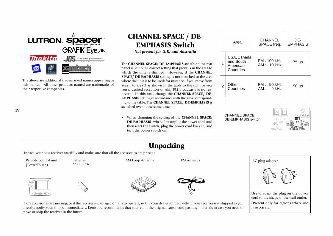
CHANNEL SPACE / DE-EMPHASIS Switch
Not present for U.K. and Australia
The CHANNEL SPACE/ DE-EMPHASIS switch on the rearpanel is set to the correct setting that prevails in the area towhich the unit is shipped. However, if the CHANNELSPACE/ DE-EMPHASIS setting is not matched to the areawhere the unit is to be used; for instance, if you move fromarea 1 to area 2 as shown in the table to the right or viceversa, desired reception of AM/ FM broadcasts is not ex-pected. In this case, change the CHANNEL SPACE/ DE-EMPHASIS setting in accordance with the area correspond-ing to the table. The CHANNEL SPACE/ DE-EMPHASIS isswitched over at the same time.
• When changing the setting of the CHANNEL SPACE/DE-EMPHASIS switch, first unplug the power cord, andthen reset the switch, plug the power cord back in, andturn the power switch on.
CHANNEL SPACEDE-EMPHASIS switch
Area CHANNELSPACE freq.
DE-EMPHASIS
USA, Canada,and SouthAmericanCountries
OtherCountries
1
2
FM : 100 kHzAM : 10 kHz
FM : 50 kHzAM : 9 kHz
75 µs
50 µs
ANTENNA
GNDAM 50 µs
AM 9kHzFM 50kHz
75 µsAM 10kHzFM 100kHz
DE-EMPHASISCHANNEL SPACE

v
Table of ContentsChapter One: Connecting Your Devices .... 1
Noting Your Devices .............................................. 3
Connecting Your Speakers .................................... 4
To Connect Front Speakers Only
To Connect Front and Surround SoundSpeakers
What if I Have a Powered Subwoofer?
To Connect Surround Back Speaker
What if I Have an Amplifier? ................................. 8
Connecting Your TV ............................................ 10
To Connect a TV
What if I Want to Watch TV without Turningon the Receiver?
Connecting Your Cable TV or Satellite Tuner ..... 12
To Connect a Cable TV Tuner with aComposite (RCA) Video Output
To Connect a Cable TV Tuner without aComposite (RCA) Video Output
To Connect a Satellite Tuner
Connecting Your VCR(s) ..................................... 14
To Connect a Primary VCR
To Connect a Secondary VCR
Connecting Your Primary CD Player .................. 16
What if I Have a Video CD-Compatible CDPlayer?
To Connect a Kenwood 200-Disc CDChanger
To Connect Any Other Primary CD Player orChanger
To Connect a Secondary CD Player
Connecting Your DVD Player .............................. 18
To Connect a DVD Player
Connecting Your CD-R Recorder ........................ 20
To Connect a CD-R Recorder
Connecting Your MD Recorder or PrimaryTape Deck ......................................................... 22
To Connect an MD Recorder
To Connect a Primary Tape Deck
To Connect a Secondary Tape Deck
Connecting Your Secondary CD Player orTape Deck ......................................................... 24
To Connect a Secondary CD Player
To Connect a Secondary Tape Deck
Connecting Your Laser Disc Player(with AC-3 RF Output) ..................................... 26
To Connect an AC-3 RF Output Laser DiscPlayer
Connecting Your Laser Disc Player(without AC-3 RF Output) ............................... 28
To Connect a PCM Digital Output Laser DiscPlayer
Connecting Your Turntable/Record Player ......... 30
To Connect a Turntable/Record Player
Connecting a Camcorder or Additional VCR ..... 31
To Connect a Camcorder or Additional VCR
Can I Connect an Additional VCR Perma-nently?
What if I Have Several Kenwood Devices (SystemControl Chaining)? .......................................... 32
Connecting the Antennas .................................... 33
AM Loop Antenna
FM Indoor Antenna
FM Outdoor Antenna
What if I Have Cable Radio?
Chapter Two: Setting Up PowerTouch ... 34
Installing the Batteries ........................................ 34
Calibrating the Touch Screen .............................. 35
Resetting PowerTouch
Selecting the Model Type .................................... 35
Navigating PowerTouch Interface ....................... 36

Table of Contents
vi
Setting Up Speakers ............................................ 37
Speaker Placement
SP Selection
SP Distance
SP Level
Bass Peak Level
Identifying Devices For PowerTouch Control ..... 40
How Do I Identify Devices?
How Do I Replace a Setup Code with a NewOne?
How Do I Delete Setup Codes?
Example of device button display
Storing Radio Stations in Memory (optional) ... 41
Storing RDS Stations Automatically
(for U.K.only)
Storing RDS Stations Name (PS Read)
(for U.K.only)
Storing Stations Manually
To Customize the PowerTouch Screen ................ 43
Changing the Name
Changing the Item Size
Moving an Item
Cutting an Item
Copying an Item
Pasting an Item
Deleting an Item
Selecting an Item in the Gallery and Pastingit in the Screen
Programming a Function in a Button (Learn)
Resetting to Default
Switching the Customized Screen to another(Jump)
To Undo the Last Operation Performed
Locking Customization Results with aPassword
Chapter Three: Setting Up on the Receiver............................................................. 46
Speaker Setup
Storing Radio Stations in Memory (op-tional)
Chapter Four: Setting Up Multiple Zones............................................................. 48
Making Connections ........................................... 49
Scenario 1: Surround Sound in Zone A only/Stereo in Zone A and Stereo in Zone B(Using the Receiver’s Speaker B Outputs)
Scenario 2: Surround Sound in Zone A andStereo in Zone B (Using a Stereo Amplifierin Zone B)
Both Scenarios: Connecting a Second TV/Monitor
Setting Up the PowerTouch ................................. 50
Connecting the External Infrared Receivers (forU.K.only) .......................................................... 51
To Connect IR Receivers (IR Transceivers)
Connecting and Setting Up On/Off Sensors orRelay Controls (for U.K.only) .......................... 52
To Connect Relay Controls
To Connect TV ON/OFF Sensors
Chapter Five: Specifications .................. 55KRF-X9995D (for U.K.)
KRF-X9995D (for Other Countries)

1
Chapter One : Connecting Your Devices
Co
nn
ection
s
Chapter One: Connecting Your DevicesWelcome to the Kenwood KRF-X9995D Connection andSetup Guide. This chapter guides you through connectingyour home entertainment devices to your new Kenwoodaudio-video receiver.
Once all your devices are connected, you can set up thePowerTouch (see Chapter Two).
Refer to the following pages for details on connecting thesedevices:
Speakers page 4TV page 10VCR(s) page 14CD Player, Kenwood 200-Disc Changer page 16DVD Player page 18CD-R Recorder page 20MD Recorder page 22Tape Deck(s) page 22Laser Disc Player page 26Turntable page 30Camcorder/Second VCR page 31Antennas page 33
All necessary cables should be provided with your homeentertainment device (not with your new receiver). If youdo not have the correct cables, you may purchase thesecables from any home entertainment store.
To make coaxial digital connections, be sure to use a high-quality digital audio cable, not a standard audio cable.
Do not plug in the receiver or any other device to AC poweruntil all connections have been made. Once all devices havebeen connected, you may plug them in and provide power.
Important:Be sure to adhere followings, or proper ventilation will beblocked causing damage or fire hazard.
Do not place any objects impairing heat radiation onto thetop of unit.
Leave a space around the unit (from the largest outside di-mension including projection) equal or greater than, shownbelow.
Top panel : 50 cm Side panel : 10 cm Back panel : 10 cm
Do not install your receiver where direct sunlight or high fre-quency fluorescent lighting can shine directly into the remotesensor. This can cause your new receiver to malfunction.
Before You BeginThis manual covers the most common and standard con-nections to the receiver. Because of its versatility, you maydecide to connect your devices differently.
Video ConnectionsThis receiver incorporates Kenwood's exclusive UniversalVideo HD, which converts between composite, S-Video andcomponent video formats. This simplifies operation, andmaintains the highest possible video quality while requir-ing only a single connection between the receiver and yourTV. Video format conversion is performed according to thefollowing chart:
If several video connections are made, one of them will beselected based on the priority 3, 2, and 1.
• Component video connections provide the best videoquality; S-Video connections provide video quality thatis superior to standard composite video connections.We recommend using the highest quality connectionpossible between the receiver and your TV.
• Since component video inputs are not downconvertedto S-Video or composite video, if you want to recordcomponents connected via component video inputs youmust also connect that component's S-Video or com-posite video outputs to the receiver.
• If you plan on using the KRF-X9995D in a Dual-Zoneapplication (see Chapter Four), you must use the com-posite video connections in addition to any componentvideo and S-Video connections for all source compo-nents. Only video sources connected to the receiver withcomposite video connections can be viewed in the sec-ond zone.
Video input signal type Appears at these video outputs
1 Composite Video CompositeS-VideoComponent Video
2 S-Video CompositeS-VideoComponent Video
3 Component Video Component Video

2
Chapter One : Connecting Your Devices
Co
nn
ecti
on
s
OPTICAL
VIDEO4
VIDEO3
VIDEO2
CD-R
MD/TAPE1
CD1
DVD
EXT.CONTROLRS-232C
DIGITAL INCOAXIAL
DIGITAL OUT
VIDEO3 IN
COMPONENT VIDEO
DVDIN
MONITOROUT
MONITOROUT
PLAYIN
PLAYIN
PLAYIN
PLAYIN
RECOUT
RECOUT
PLAYIN
S VIDEO VIDEOPRE OUTZONE B PRE OUT
R LAUDIO
R LFRONTR LSURROUNDR LR L SURROUND BACKSUB WOOFER CENTERVIDEO
R LB A
AUDIO
VIDEO1
VIDEO2
VIDEO3
VIDEO4
DVD FRONT
DVD/6CH.
INPUT
SURROUND
CENTER SUBWOOFER
PHONO
CD1
RECOUT
PLAYIN
MD/TAPE1
RECOUT
PLAYIN
CD-R
RECOUT
PLAYIN
CD2/TAPE2
MONITOR
CENTERSPEAKER
(6–16Ω)
SURROUNDSPEAKERS
(6–16Ω)
AC 120V 60HzSWITCHED TOTAL90W 0.75A MAX.
FRONT SPEAKERS(6–16Ω)
ANTENNA
GNDAM
FM 75Ω
SYSTEMCONTROL
SL16 TEXT
REMOTE
TV ON/OFFSENSOR
RELAYCONTROL
IR OUTLCD
REMOTE
IR RECEIVERIN
IR RECEIVERIN
DVD CONTROL
C
R
L
R
L
A B
DC5V 10mADC12V 20mADC12V 20mA DC12V 20mA
AC 220 – 240V
AC 110 –120V
50 µsAM 9kHzFM 50kHz
75 µsAM 10kHzFM 100kHz
DE-EMPHASISCHANNEL SPACE
PR/CR
PB/CB
Y
PR/CR
PB/CB
Y
PR/CR
PB/CB
Y
IR OUT LCD
AC Plugs
AC voltage
selector switch
(only for some
areas)
Speaker wire
binding post
Zone B pre out jacks
Video componentjacks
Audio component jacks
Pre out jacks
Antenna jacks
Supplemental infrared receiverand sensor jacks, DVD controljacks**, RELAY CONTROL jackand TV ON/OFF SENSOR jack(for U.K. only)
The shape ofplugs aredifferent betweencountries
Note that some component jacks are linked to spe-
cific digital jacks. For example, if you connect a video
component with a digital optical cable, you should con-
nect the analog cables to the VIDEO2 video component
jacks and the digital cable to the VIDEO2 digital optical
jack.
System control jacks
The following diagram shows the entire back of the KRF-X9995D.
Channel space/FM de-emphasis switch
(only for some areas)RS-232Cconnector*
Digital jacks
(coaxial and optical)
* The RS-232C connector is provided for future capability (to connect a commercially marketedcontroller having the capability of controlling the KRF-X9995D).
**The DVD CONTROL jacks are reserved for future extension of the system.

3
Chapter One : Connecting Your Devices
Co
nn
ection
s
Noting Your Devices
Use this table and the diagram on the preceding page toplan your connections before you make them, or use it torecord your connections as you make them.
You will need this information later, when you set up yourPowerTouch (see “Identifying Devices For PowerTouch Con-trol” on page 40). Recording this information now will saveyou additional trips behind your home entertainment cabi-net. You will fill in the Setup Code column when you aresetting up PowerTouch.
Jack Set Device Manufacturer Model # Setup Code
PHONO
CD1
MD/TAPE1
CD2/TAPE2 MONITOR
CD-R
VIDEO1
VIDEO2
VIDEO3
VIDEO4
DVD
MONITOR OUT
(TV on PowerTouch)
When playing Dolby Digital* or DTS-encoded software inmultichannel configuration, the connected audio signalshould be the digital signal.* When playing a LaserDisc recorded in the Dolby Digitalformat, connect the AC-3 RF output to the receiver (See page26).
4
Chapter One : Connecting Your Devices
Co
nn
ecti
on
s
Connecting Your Speakers
OPTICAL
VIDEO4
VIDEO3
VIDEO2
CD-R
MD/TAPE1
CD1
DVD
EXT.CONTROLRS-232C
DIGITAL INCOAXIAL
DIGITAL OUT
VIDEO3 IN
COMPONENT VIDEO
DVDIN
MONITOROUT
MONITOROUT
PLAYIN
PLAYIN
PLAYIN
PLAYIN
RECOUT
RECOUT
PLAYIN
S VIDEO VIDEOPRE OUTZONE B PRE OUT
R LAUDIO
R LFRONTR LSURROUNDR LR L SURROUND BACKSUB WOOFER CENTERVIDEO
R LB A
AUDIO
VIDEO1
VIDEO2
VIDEO3
VIDEO4
DVD FRONT
DVD/6CH
INPUT
SURROUND
CENTER SUBWOOFER
PHONO
CD1
RECOUT
PLAYIN
MD/TAPE1
RECOUT
PLAYIN
CD-R
RECOUT
PLAYIN
CD2/TAPE2
MONITOR
CENTERSPEAKER
(6–16Ω)
SURROUNDSPEAKERS
(6–16Ω)
AC 120V 60HzSWITCHED TOTAL90W 0.75A MAX.
FRONT SPEAKERS(6–16Ω)
ANTENNA
GNDAM
FM 75Ω
SYSTEMCONTROL
SL16 TEXT
REMOTE
TV ON/OFFSENSOR
RELAYCONTROL
IR OUTLCD
IR OUT LCDREMOTE
IR RECEIVERIN
IR RECEIVERIN
DVD CONTROL
C
R
L
R
L
A B
DC5V 10mADC12V 20mADC12V 20mA DC12V 20mA
AC 220 – 240V
AC 110 –120V
50 µsAM 9kHzFM 50kHz
75 µsAM 10kHzFM 100kHz
DE-EMPHASISCHANNEL SPACE
PR/CR
PB/CB
Y
PR/CR
PB/CB
Y
PR/CR
PB/CB
Y
RFRONT
LFRONT
RSURROUND
LSURROUND
CENTER

5
Chapter One : Connecting Your Devices
Co
nn
ection
s
Connecting Your Speakers, continued
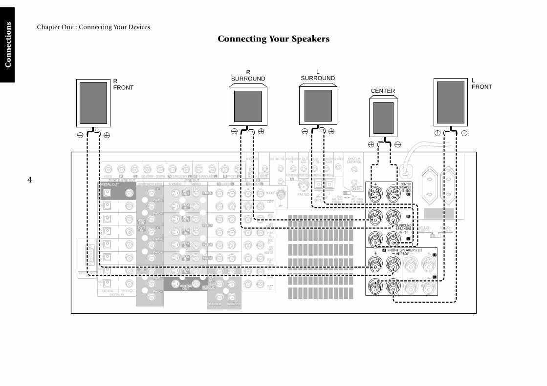
Do not plug in the receiver to AC power until all connec-tions have been made.
To Connect Front Speakers Only:If you only intend to listen to stereo sound (as opposed tosurround sound), you may simply connect a single pair ofspeakers. To do so:
Using Banana Plugs (except for U.K.):
1. Tighten the speaker wire binding posts. If you do nottighten the posts, they will not conduct sound properlyto the speakers.
2. Insert the plug from the positive jack on the RIGHTFRONT speaker into the pin jack on the positive RIGHTFRONT post. Repeat for the negative plug.
3. Repeat step 2 for the positive and negative wires on theLEFT FRONT speaker.
Using Bare Wires:
1. Loosen the speaker wire binding posts.
2. Insert the wire from the positive jack on the RIGHTFRONT speaker into the U-shaped slot in the base ofthe positive RIGHT FRONT post. Lay the wire to theright of the post; that way, when you tighten the bind-ing post, it will naturally twist the wire into the bestconnection. Tighten the post. Repeat for the negative wireon the RIGHT FRONT speaker as shown to the right.
3. Repeat step 2 for the positive and negative wires on theLEFT FRONT speaker.
To Connect Front and Surround SoundSpeakers:To listen to the full surround sound that this receiver canput out, connect front speakers, center, left surround, andright surround speakers. To do so:
To reproduce more enriched bass, connect a subwooferincorporating a power amplifier.
For the connections of the subwoofer and surround backspeakers, see page 6 to 7.
Using Banana Plugs (except for U.K.):
1. Tighten the speaker wire binding posts. If you do nottighten the posts, they will not conduct sound properlyto the speakers.
2. Follow the steps under “To Connect Front SpeakersOnly” on this page to connect the RIGHT and LEFTFRONT speakers.
3. Insert the plug from the positive jack on the CENTERspeaker into the pin jack on the positive CENTER post.Repeat for the negative plug.
4. Insert the plug from the positive jack on the RIGHTSURROUND speaker into the pin jack on the positiveRIGHT SURROUND post. Repeat for the negative plug.
5. Repeat step 4 for the positive and negative wires on theLEFT SURROUND speaker.
Using Bare Wires:
1. Loosen the speaker wire binding posts.
2. Follow the steps under “To Connect Front SpeakersOnly” on this page to connect the RIGHT and LEFTFRONT speakers.
3. Insert the wire from the positive jack on the CENTERspeaker into the U-shaped slot in the base of the positiveCENTER post as shown to the right.
Tighten the post. Repeat for the negative wire.
4. Insert the wire from the positive jack on the RIGHT SUR-ROUND speaker into the U-shaped slot on the base ofthe positive RIGHT SURROUND post. Tighten the post.Repeat for the negative wire.
5. Repeat step 4 for the positive and negative wires on theLEFT SURROUND speaker.
Never short circuit the + and - speaker wires.
Do not switch the left and right speaker wires or swap the +and - wires on the binding posts.
The speakers must have a nominal impedance of between6Ω and 16Ω.
Using Bare Wires
1. Loosen post
2. Insert wire
3. Tighten post

6
Chapter One : Connecting Your Devices
Co
nn
ecti
on
s
Connecting Your Speakers, continued
REMOTE
IR OUT LCD
OPTICAL
VIDEO4
VIDEO3
VIDEO2
CD-R
MD/TAPE1
CD1
DVD
EXT.CONTROLRS-232C
DIGITAL INCOAXIAL
DIGITAL OUT
VIDEO3 IN
COMPONENT VIDEO
DVDIN
MONITOROUT
MONITOROUT
PLAYIN
PLAYIN
PLAYIN
PLAYIN
RECOUT
RECOUT
PLAYIN
S VIDEO VIDEOPRE OUTZONE B PRE OUT
R LAUDIO
R LFRONTR LSURROUNDR LR L SURROUND BACKSUB WOOFER CENTERVIDEO
R LB A
AUDIO
VIDEO1
VIDEO2
VIDEO3
VIDEO4
DVD FRONT
DVD/6CH
INPUT
SURROUND
CENTER SUBWOOFER
PHONO
CD1
RECOUT
PLAYIN
MD/TAPE1
RECOUT
PLAYIN
CD-R
RECOUT
PLAYIN
CD2/TAPE2
MONITOR
CENTERSPEAKER
(6–16Ω)
SURROUNDSPEAKERS
(6–16Ω)
AC 120V 60HzSWITCHED TOTAL90W 0.75A MAX.
FRONT SPEAKERS(6–16Ω)
ANTENNA
GNDAM
FM 75Ω
SYSTEMCONTROL
SL16 TEXT
REMOTE
TV ON/OFFSENSOR
RELAYCONTROL
IR OUTLCD
IR RECEIVERIN
IR RECEIVERIN
DVD CONTROL
C
R
L
R
L
A B
DC12V 20mADC12V 20mADC12V 20mA DC12V 20mA
AC 220 – 240V
AC 110 –120V
DE-EMPHASISCHANNEL SPACE
PR/CR
PB/CB
Y
PR/CR
PB/CB
Y
PR/CR
PB/CB
Y
50 µsAM 9kHzFM 50kHz
75 µsAM 10kHzFM 100kHz
RSURROUNDBACK
LSURROUNDBACK
Power Amp.
POWEREDSUBWOOFER

7
Chapter One : Connecting Your Devices
Co
nn
ection
s
Connecting Your Speakers, continued
Do not plug in the amplifiers or the receiver to AC poweruntil all connections have been made.
What if I Have a Powered Subwoofer?Simply connect the subwoofer’s audio cable to the receiver’sSUBWOOFER PRE OUT jack as shown to the left.
To Connect Surround Back Speakers:To reproduce the surround back channels by Dolby DigitalSurround EX, DTS-ES or DTS-NEO:6, add a commerciallymarketed 2-channel power amplifier and connect thesurround back speakers to it.
To connect supplemental power amplifiers and surroundback speakers:
1. Using RCA audio cables (not supplied), connect thereceiver’s SURROUND BACK PRE OUT jacks to theamplifiers’ input jacks as shown to the left.
2. Connect the speakers to the power amplifiers accordingto the amplifiers’ instruction manuals.

8
Chapter One : Connecting Your Devices
Co
nn
ecti
on
s
What if I Have an Amplifier?
OPTICAL
VIDEO4
VIDEO3
VIDEO2
CD-R
MD/TAPE1
CD1
DVD
EXT.CONTROLRS-232C
DIGITAL INCOAXIAL
DIGITAL OUT
VIDEO3 IN
COMPONENT VIDEO
DVDIN
MONITOROUT
MONITOROUT
PLAYIN
PLAYIN
PLAYIN
PLAYIN
RECOUT
RECOUT
PLAYIN
S VIDEO VIDEOPRE OUTZONE B PRE OUT
R LAUDIO
R LFRONTR LSURROUNDR LR L SURROUND BACKSUB WOOFER CENTERVIDEO
R LB A
AUDIO
VIDEO1
VIDEO2
VIDEO3
VIDEO4
DVD FRONT
DVD/6CH
INPUT
SURROUND
CENTER SUBWOOFER
PHONO
CD1
RECOUT
PLAYIN
MD/TAPE1
RECOUT
PLAYIN
CD-R
RECOUT
PLAYIN
CD2/TAPE2
MONITOR
CENTERSPEAKER
(6–16Ω)
SURROUNDSPEAKERS
(6–16Ω)
AC 120V 60HzSWITCHED TOTAL90W 0.75A MAX.
FRONT SPEAKERS(6–16Ω)
ANTENNA
GNDAM
FM 75Ω
SYSTEMCONTROL
SL16 TEXT
REMOTE
TV ON/OFFSENSOR
RELAYCONTROL
IR OUTLCD
IR RECEIVERIN
IR RECEIVERIN
DVD CONTROL
C
R
L
R
L
A B
DC5V 10mADC12V 20mADC12V 20mA DC12V 20mA
AC 220 – 240V
AC 110 –120V
DE-EMPHASISCHANNEL SPACE
PR/CR
PB/CB
Y
PR/CR
PB/CB
Y
PR/CR
PB/CB
Y
50 µsAM 9kHzFM 50kHz
75 µsAM 10kHzFM 100kHz
REMOTE
IR OUT LCD
R FRONT L FRONT
Power Amp.
R SURROUND L SURROUND
Power Amp.
CENTER
Power Amp.

9
Chapter One : Connecting Your Devices
Co
nn
ection
s
What if I Have an Amplifier?, continued
You can use supplemental power amplifiers for any of thechannels instead of the receiver’s built-in amplifiers.
Do not plug in the amplifiers or the receiver to AC poweruntil all connections have been made.
To connect supplemental power amplifiers:
1. Using RCA audio cables (not supplied), connect thereceiver’s PRE OUT jacks to the amplifiers’ input jacksas shown to the left.
2. Connect the speakers to the power amplifiers accordingto the amplifiers’ instruction manuals.
10
Chapter One : Connecting Your Devices
Co
nn
ecti
on
s
Connecting Your TV
OPTICAL
VIDEO4
VIDEO3
VIDEO2
CD-R
MD/TAPE1
CD1
DVD
EXT.CONTROLRS-232C
DIGITAL INCOAXIAL
DIGITAL OUT
VIDEO3 INDVDIN
MONITOROUT
MONITOROUT
PLAYIN
PLAYIN
PLAYIN
PLAYIN
RECOUT
RECOUT
PLAYIN
S VIDEO VIDEOPRE OUTZONE B PRE OUT
R LAUDIO
R LFRONTR LSURROUNDR LR L SURROUND BACKSUB WOOFER CENTERVIDEO
R LB A
AUDIO
VIDEO1
VIDEO2
VIDEO3
VIDEO4
DVD FRONT
DVD/6CH
INPUT
SURROUND
CENTER SUBWOOFER
PHONO
CD1
RECOUT
PLAYIN
MD/TAPE1
RECOUT
PLAYIN
CD-R
RECOUT
PLAYIN
CD2/TAPE2
MONITOR
ANTENNA
GNDAM
FM 75Ω
SYSTEMCONTROL
SL16 TEXT
REMOTE
TV ON/OFFSENSOR
RELAYCONTROL
IR OUTLCD
IR RECEIVERIN
IR RECEIVERIN
DVD CONTROL
A
DC5V 10mADC12V 20mADC12V 20mA DC12V 20mA
DE-EMPHASISCHANNEL SPACE
COMPONENT VIDEO
PR/CR
PB/CB
Y
PR/CR
PB/CB
Y
PR/CR
PB/CB
Y
50 µsAM 9kHzFM 50kHz
75 µsAM 10kHzFM 100kHz
REMOTE
IR OUT LCD
COMPOSITE VIDEO IN
COMPONENT VIDEO IN
S-VIDEO IN

11
Chapter One : Connecting Your Devices
Co
nn
ection
s
Connecting Your TV, continued
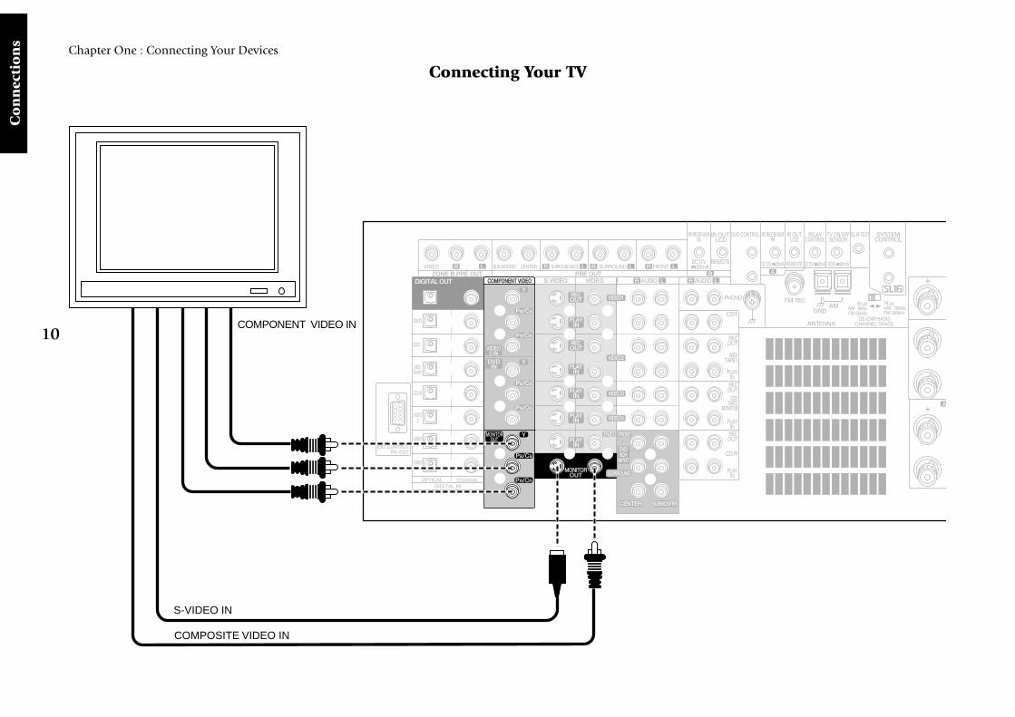
Do not plug in the receiver or devices to AC power untilyou have connected all your devices.
This section focuses on the connections from your TV tothe KRF-X9995D. Please refer to your TV’s instructions formore detail about its connection jacks and capabilities.
The instructions in this section show how to connect yourTV as a monitor for the other video devices you connect(without using it as an audio/video source device itself). Touse your TV as an audio/video source device, you must firstconnect it as described in this section, and also connect itsaudio/video output jacks as if they were cable TV tuner out-puts, as described in “To Connect a Cable TV Tuner with aComposite (RCA) Video Output” on page 13.
To Connect a TV:1. Review the information under “Before You Begin” on
page 1. It contains important notes about the types ofvideo connections you can make.
2. Connect a video cable from your TV’s Video IN jack tothe receiver’s MONITOR OUT jack as shown to the left.
3. If your TV has the COMPONENT VIDEO jacks, you canalso connect it as shown on the left.
4. If your TV does not have any video input connections,you must purchase an RF modulator. The modulatorwill convert the video signal from the receiver to an RFsignal that will work with the TV’s antenna connections.
Connect the receiver to the TV according to the RFmodulator’s instruction manual.
5. Go to “Noting Your Devices” on page 3 and note whichjack you used to connect your TV. In addition, note thebrand name and model number of the TV.
If you previously connected your TV directly to your VCR,you must now connect it through your new receiver.
What if I Want to Watch TV without Turningon the Receiver?The connection described here sets your TV up as a monitoryou can use to view media played on your other video de-vices (such as a VCR or DVD player). You can still watch TVwithout having to use the receiver.
With some devices, the COMPONENT VIDEO jacks (Y, PB/CB, PR/CR jacks) are indicated as the R-Y, B-Y jacks. Fordetails, refer to the operation instructions for the respectivedevice.

12
Chapter One : Connecting Your Devices
Co
nn
ecti
on
s
OPTICAL
VIDEO4
VIDEO3
VIDEO2
CD-R
MD/TAPE1
CD1
DVD
EXT.CONTROLRS-232C
DIGITAL INCOAXIAL
DIGITAL OUT
VIDEO3 IN
PR/CR
PB/CB
Y
PR/CR
PB/CB
Y
PR/CR
PB/CB
YCOMPONENT VIDEO
DVDIN
MONITOROUT
MONITOROUT
PLAYIN
PLAYIN
PLAYIN
RECOUT
RECOUT
PLAYIN
S VIDEO VIDEOPRE OUTZONE B PRE OUT
R LAUDIO
R LFRONTR LSURROUNDR LR L SURROUND BACKSUB WOOFER CENTERVIDEO
R LB A
AUDIO
VIDEO1
VIDEO2
VIDEO4
DVD FRONT
DVD/6CH
INPUT
SURROUND
CENTER SUBWOOFER
PHONO
CD1
RECOUT
PLAYIN
MD/TAPE1
RECOUT
PLAYIN
CD-R
RECOUT
PLAYIN
CD2/TAPE2
MONITOR
CENTERSPEAKER
(6–16Ω)
SURROUNDSPEAKERS
(6–16Ω)
FRONT SPEAKERS(6–16Ω)
ANTENNA
GNDAM
FM 75Ω
SYSTEMCONTROL
SL16 TEXT
REMOTE
TV ON/OFFSENSOR
RELAYCONTROL
IR OUTLCD
IR RECEIVERIN
IR RECEIVERIN
DVD CONTROL
C
R
L
A
DC5V 10mADC12V 20mADC12V 20mA DC12V 20mA
DE-EMPHASISCHANNEL SPACE
PLAYIN VIDEO3
50 µsAM 9kHzFM 50kHz
75 µsAM 10kHzFM 100kHz
REMOTE
IR OUT LCD
Remove protective cap before connecting.
AUDIO OUT
VIDEO OUT
S-VIDEO OUT
DIGITAL OUT- OPTICAL or COAXIAL
COMPONENT VIDEO OUT
Connecting Your Cable TV or Satellite Tuner
Note that video device jacks are linked to specific digitaljacks.
As a result, every digital cable or analog cable should beconnected between jacks having the same name.
13
Chapter One : Connecting Your Devices
Co
nn
ection
s
Connecting Your Cable TV or Satellite Tuner, continued
Do not plug in the receiver or devices to AC power untilyou have connected all your devices.
This section focuses on the connections from your cable orsatellite tuner to the KRF-X9995D. Please refer to yourtuner’s instructions for more detail about its connectionjacks and capabilities.
The instructions in this section show one of several pos-sible variations on connecting your tuner. For further assis-tance on optional configurations, contact your cable or sat-ellite provider.
To Connect a Cable TV Tuner with aComposite (RCA) Video Output:1. Review the information under “Before You Begin” on
page 1. It contains important notes about the types ofvideo connections you can make.
2. Connect the audio and video cables from the cabletuner’s Audio and Video OUT jacks to the receiver’sVIDEO2, VIDEO3, or VIDEO4 PLAY IN jacks as shownto the left.
When the component video cables are connected, theaudio and video cables of the cable TV tuner should beconnected to the VIDEO3 jacks of the receiver.
3. If your cable TV tuner and TV have the COMPONENTVIDEO jacks, you can also connect them as shown on theleft.
4. Go to “Noting Your Devices” on page 3 and note whichjack you used to connect your tuner. In addition, notethe brand name and model number of the tuner.
To Connect a Cable TV Tuner without aComposite (RCA) Video Output:1. Connect the audio cables from the cable tuner’s Audio
Out jacks to the receiver’s VIDEO2, VIDEO3, or VIDEO4PLAY IN jacks as shown to the left.
2. Leave the cable tuner’s video out (RF jack) connecteddirectly to your VCR or TV (wherever you already haveit connected).
3. Go to “Noting Your Devices” on page 3 and note whichjack you used to connect your tuner. In addition, notethe brand name and model number of the tuner.
To Connect a Satellite Tuner:1. Review the information under “Before You Begin” on
page 1. It contains important notes about the types ofvideo connections you can make.
2. If your satellite tuner has a digital output jack, connecta digital (optical or coaxial) cable between the satellitetuner’s digital output jack and the receiver’s VIDEO2,VIDEO3 or VIDEO4 digital input jack as shown in thefigure on the left.
The illustration shows two digital connections, one forcoaxial connection and one for optical connection. Yoursatellite tuner supports one or the other of these con-nection methods—do not connect both.
3. Connect the audio and video cables from the satellitetuner’s Audio and Video out jacks to the receiver’sVIDEO2, VIDEO3, or VIDEO4 PLAY IN jacks as shownto the left.
Note that the jack sets are linked, even though they arenot adjacent. You must connect all of the cables fromyour satellite tuner to a linked jack set. For example, ifyou connect the analog cables to VIDEO2 and the digi-tal optical cable to VIDEO3, your satellite tuner willnot work correctly.
When the component video cables are connected, theaudio and video cables of the satellite tuner should beconnected to the VIDEO3 jacks of the receiver.
4. If your satellite tuner and TV have the COMPONENTVIDEO jacks, you can also connect them as shown on theleft.
5. Go to “Noting Your Devices” on page 3 and note whichjack you used to connect your tuner. In addition, notethe brand name and model number of the tuner.
When playing Dolby Digital or DTS-encoded software inmultichannel configuration, the connected audio signalshould be the digital signal.

14
Chapter One : Connecting Your Devices
Co
nn
ecti
on
s
Connecting Your VCR(s)
OPTICAL
VIDEO4
VIDEO3
VIDEO2
CD-R
MD/TAPE1
CD1
DVD
EXT.CONTROLRS-232C
DIGITAL INCOAXIAL
DIGITAL OUT
VIDEO3 IN
COMPONENT VIDEO
DVDIN
MONITOROUT
MONITOROUT
PLAYIN
PLAYIN
PLAYIN
PLAYIN
RECOUT
RECOUT
PLAYIN
S VIDEO VIDEOPRE OUTZONE B PRE OUT
R LAUDIO
R LFRONTR LSURROUNDR LR L SURROUND BACKSUB WOOFER CENTERVIDEO
R LB A
AUDIO
VIDEO1
VIDEO2
VIDEO3
VIDEO4
DVD FRONT
DVD/6CH
INPUT
SURROUND
CENTER SUBWOOFER
PHONO
CD1
RECOUT
PLAYIN
MD/TAPE1
RECOUT
PLAYIN
CD-R
RECOUT
PLAYIN
CD2/TAPE2
MONITOR
CENTERSPEAKER
(6–16Ω)
SURROUNDSPEAKERS
(6–16Ω)
FRONT SPEAKERS(6–16Ω)
ANTENNA
GNDAM
FM 75Ω
SYSTEMCONTROL
SL16 TEXT
REMOTE
TV ON/OFFSENSOR
RELAYCONTROL
IR OUTLCD
IR RECEIVERIN
IR RECEIVERIN
DVD CONTROL
C
R
L
A
DC5V 10mADC12V 20mADC12V 20mA DC12V 20mA
DE-EMPHASISCHANNEL SPACE
PR/CR
PB/CB
Y
PR/CR
PB/CB
Y
PR/CR
PB/CB
Y
50 µsAM 9kHzFM 50kHz
75 µsAM 10kHzFM 100kHz
REMOTE
IR OUT LCD
AUDIO IN
VIDEO OUT
S-VIDEO OUT
S-VIDEO IN
AUDIO OUT
VIDEO IN

15
Chapter One : Connecting Your Devices
Co
nn
ection
s
Connecting Your VCR(s), continued
Do not plug in the receiver to AC power until you haveconnected all your devices.
This section focuses on the connections from your VCR tothe KRF-X9995D. Please refer to your VCR’s instructionsfor more detail about its connection jacks and capabilities.
The instructions in this section show one of several pos-sible variations on connecting your VCR. For further assis-tance on optional configurations, contact the store whereyou purchased your receiver.
To Connect a Primary VCR:1. Review the information under “Before You Begin” on
page 1. It contains important notes about the types ofvideo connections you can make.
2. Connect the audio and video cables from the VCR’sAudio and Video jacks to the receiver’s VIDEO1 RECOUT and PLAY IN jacks as shown to the left.
3. Be sure to connect the VCR VIDEO IN cable to the jacklabeled REC OUT and the VIDEO OUT cable to the jacklabeled PLAY IN.
4. Go to “Noting Your Devices” on page 3 and note whichjack you used to connect your VCR. In addition, notethe brand name and model number of the VCR.
To Connect a Secondary VCR:1. Review the information under “Before You Begin” on
page 1. It contains important notes about the types ofvideo connections you can make.
2. Connect the audio and video cables from the VCR’sAudio and Video jacks to the receiver’s VIDEO2 jacks.
3. Go to “Noting Your Devices” on page 3 and note whichjack you used to connect your VCR. In addition, notethe brand name and model number of the VCR.

16
Chapter One : Connecting Your Devices
Co
nn
ecti
on
s
Connecting Your Primary CD Player
OPTICAL
VIDEO4
VIDEO3
VIDEO2
CD-R
MD/TAPE1
CD1
DVD
EXT.CONTROLRS-232C
DIGITAL INCOAXIAL
DIGITAL OUT
VIDEO3 IN
COMPONENT VIDEO
DVDIN
MONITOROUT
MONITOROUT
PLAYIN
PLAYIN
PLAYIN
PLAYIN
RECOUT
RECOUT
PLAYIN
S VIDEO VIDEOPRE OUTZONE B PRE OUT
R LAUDIO
R LFRONTR LSURROUNDR LR L SURROUND BACKSUB WOOFER CENTERVIDEO
R LB A
AUDIO
VIDEO1
VIDEO2
VIDEO3
VIDEO4
DVD FRONT
DVD/6CH
INPUT
SURROUND
CENTER SUBWOOFER
PHONO
CD1
RECOUT
PLAYIN
MD/TAPE1
RECOUT
PLAYIN
CD-R
RECOUT
PLAYIN
CD2/TAPE2
MONITOR
CENTERSPEAKER
(6–16Ω)
SURROUNDSPEAKERS
(6–16Ω)
FRONT SPEAKERS(6–16Ω)
ANTENNA
GNDAM
FM 75Ω
SYSTEMCONTROL
SL16 TEXT
REMOTE
TV ON/OFFSENSOR
RELAYCONTROL
IR OUTLCD
IR RECEIVERIN
IR RECEIVERIN
DVD CONTROL
C
R
L
A B
DC5V 10mADC12V 20mADC12V 20mA DC12V 20mA
A12
DE-EMPHASISCHANNEL SPACE
PR/CR
PB/CB
Y
PR/CR
PB/CB
Y
PR/CR
PB/CB
Y
50 µsAM 9kHzFM 50kHz
75 µsAM 10kHzFM 100kHz
REMOTE
IR OUT LCD
OUTPUT A (CD1)
OUTPUT B (CD2)*
COMMUNICATION CABLE - KENWOOD ONLY
SYSTEM CONTROL CABLE - KENWOOD ONLY
*KENWOOD DPF-J9030, DPF-J9020 or DPF-J9010 ONLY
Remove protective capbefore connecting.
DIGITAL OUT - OPTICAL or COAXIAL
$ ›
&
^
PUSH OPEN)

17
Chapter One : Connecting Your Devices
Co
nn
ection
s
Connecting Your Primary CD Player, continued
Do not plug in the receiver to AC power until you haveconnected all your devices.
This section focuses on the connections from your 200-DiscCD Changer to the KRF-X9995D. Please refer to yourchanger’s instructions for more detail about its connectionjacks and capabilities.
Each set of instructions in this section shows one of severalpossible variations on connecting your CD player(s). Forfurther assistance on optional configurations, contact thestore where you purchased your CD player(s).
The illustration shows a Kenwood 200-Disc CD Changer.Your CD player may look different.
The Kenwood DPF-J9030, DPF-J9020 and DPF-J9010 200-Disc Changers contain two CD transports. You must con-nect these devices as though they were two CD players.
What if I Have a Video CD-Compatible CDPlayer?Connect the audio and video cables from the CD player toany unused Video jack set.
Do not connect the system control cable in this instance.
To Connect a Kenwood 200-Disc CDChanger:1. Connect one set of audio cables from the 200-Disc
Changer to the receiver’s CD1 jacks. If you have a DPF-J9030, DPF-J9020 or DPF-J9010, connect Output A tothe receiver’s CD1 jacks and Output B to the receiver’sCD2/TAPE2 MONITOR PLAY IN jacks as shown to theleft.
2. Connect the digital cable from the changer to thereceiver’s CD1 digital jack as shown to the left.
The illustration shows two digital connections, one forcoaxial connection and one for optical connection. YourCD player supports one or the other of these connec-tion methods—do not connect both.
3. Connect the system control cable from the changer tothe SYSTEM CONTROL jack as shown to the left.
Be sure that the SL16/XS8 switch on the changer is setto SL16.
If you are connecting more than one Kenwood devicewith a system control cable, see “What if I Have SeveralKenwood Devices (System Control Chaining)?” onpage 32 for more information.
4. Connect the SL16 text cable (communication cable)from the changer to the receiver’s SL16 TEXT jack asshown to the left.
5. Go to “Noting Your Devices” on page 3 and note whichjacks you used to connect your CD changer. In addi-tion, note the brand name and model number of theCD Changer.
To Connect Any Other Primary CD Player orChanger:1. Connect the audio cables from the CD player’s audio
jacks to the receiver’s CD1 jack set as shown to the left.
2. Connect the digital cable from the CD player’s digitaljack to the receiver’s CD1 digital jack as shown to theleft.
The illustration shows two digital connections, one forcoaxial connection and one for optical connection. YourCD player supports one or the other of these connec-tion methods—do not connect both.
3. If you are connecting a Kenwood CD Player with sys-tem control, connect the SYSTEM CONTROL cable fromthe CD player to the system control jack as shown tothe left.
Be sure that the SL16/XS8 switch on the player/changeris set to SL16.
If you are connecting more than one Kenwood devicewith a system control cable, see “What if I Have SeveralKenwood Devices (System Control Chaining)?” onpage 32 for more information.
4. Go to “Noting Your Devices” on page 3 and note whichjacks you used to connect your CD player/changer. Inaddition, note the brand name and model number ofthe CD player or changer.
To Connect a Secondary CD Player:See “Connecting Your Secondary CD Player or Tape Deck”on page 24.
Do not connect the system control cable in this instance.
When playing a HDCD disc in the HDCD format (highquality mode), use the digital connection jack.

18
Chapter One : Connecting Your Devices
Co
nn
ecti
on
s
Connecting Your DVD Player
OPTICAL
VIDEO4
VIDEO3
VIDEO2
CD-R
MD/TAPE1
CD1
DVD
EXT.CONTROLRS-232C
DIGITAL INCOAXIAL
DIGITAL OUT
VIDEO3 INDVDIN
MONITOROUT
MONITOROUT
PLAYIN
PLAYIN
PLAYIN
PLAYIN
RECOUT
RECOUT
PLAYIN
PRE OUTZONE B PRE OUTR LFRONTR LSURROUNDR LR L SURROUND BACKSUB WOOFER CENTERVIDEO
R LB A
AUDIO
VIDEO1
VIDEO2
VIDEO3
VIDEO4
DVD FRONT
DVD/6CH.
INPUT
SURROUND
CENTER SUBWOOFER
PHONO
CD1
RECOUT
PLAYIN
MD/TAPE1
RECOUT
PLAYIN
CD-R
RECOUT
PLAYIN
CD2/TAPE2
MONITOR
ANTENNA
GNDAM
FM 75Ω
SYSTEMCONTROL
SL16 TEXT
REMOTE
TV ON/OFFSENSOR
RELAYCONTROL
IR OUTLCD
IR RECEIVERIN
IR RECEIVERIN
DVD CONTROL
DC5V 10mADC12V 20mADC12V 20mA DC12V 20mA
DE-EMPHASISCHANNEL SPACE
COMPONENT VIDEO S VIDEO VIDEO R LAUDIO
PR/CR
PB/CB
Y
PR/CR
PB/CB
Y
PR/CR
PB/CB
Y
50 µsAM 9kHzFM 50kHz
75 µsAM 10kHzFM 100kHz
REMOTE
IR OUT LCD
Remove protective capbefore connecting.
SUBWOOFER OUT
CENTER OUT
SURROUND OUT
MIX LINE OUT or FRONT OUT
VIDEO OUT
S-VIDEO OUT
DIGITAL OUT - OPTICAL or COAXIAL
COMPONENT VIDEO OUT
3
8
7
¢4

19
Chapter One : Connecting Your Devices
Co
nn
ection
s
Connecting Your DVD Player, continued
Do not plug in the receiver to AC power until you haveconnected all your devices.
This section focuses on the connections from your DVDplayer to the KRF-X9995D. Please refer to your DVD player’sinstructions for more detail about its connection jacks andcapabilities.
The instructions in this section show one of several pos-sible variations on connecting your DVD player. For furtherassistance on optional configurations, contact the storewhere you purchased your receiver.
To Connect a DVD Player:1. Review the information under “Before You Begin” on
page 1. It contains important notes about the types ofvideo connections you can make.
2. Connect the video cables from the DVD’s Video jacks tothe receiver’s DVD PLAY IN jacks as shown to the left.
If your DVD and TV have the COMPONENT VIDEO jacks,you can also connect them as shown on the left.
3. Connect the audio cables from the DVD’s audio jacks(AUDIO OUT, FRONT or MIX LINE OUT) to thereceiver’s FRONT jacks of DVD/6CH. INPUT.
When the DVD player provides the DVD 6CH (DVD 5.1CH) outputs, connect them to the FRONT, SUR-ROUND, CENTER and SUBWOOFER input jacks. (op-tional)
4. Connect the digital cable (either optical or coaxial) fromthe DVD’s digital jack to the appropriate digital jack onthe receiver as shown to the left.
The illustration shows two digital connections, one forcoaxial connection and one for optical connection. YourDVD player supports one or the other of these connec-tion methods—do not connect both.
If you use the optical digital cable, be sure to removethe protective cover from the optical jack before con-necting.
5. Go to “Noting Your Devices” on page 3 and note whichjacks you used to connect your DVD player. In addi-tion, note the brand name and model number of theDVD player.
DTS disclaimer clauseDTS Digital Surround™ is a discrete 5.1 channel digital audio format available on CD, LD, and DVD software which consequently cannot be decoded and played back inside most CD, LD,or DVD players. For this reason, when DTS-encoded software is played back through the analog outputs of the CD, LD, or DVD player, excessive noise will be exhibited. To avoid possibledamage to the audio system, proper precautions should taken by the consumer if the analog outputs are connected directly to an amplification system. To enjoy DTS Digital Surround™playback, an external 5.1 channel DTS Digital Surround™ decoder system must be connected to the digital output (S/PDIF, AES/EBU, or TosLink) of the CD, LD or DVD player.
This unit is equipped with DTS Digital Surround™ decoder.
When playing Dolby Digital or DTS-encoded software inmultichannel configuration, the connected audio signalshould be the digital signal.
The digital inputs of the KRF-X9995D are not compatiblewith an audio signal with 192 kHz sampling frequency or96 kHz multichannel audio signal. These signals should beinput to the analog or DVD/6CH. INPUT jacks.

20
Chapter One : Connecting Your Devices
Co
nn
ecti
on
s
Connecting Your CD-R Recorder
OPTICAL
VIDEO4
VIDEO3
VIDEO2
CD-R
MD/TAPE1
CD1
DVD
EXT.CONTROLRS-232C
DIGITAL INCOAXIAL
DIGITAL OUT
VIDEO3 IN
COMPONENT VIDEO
DVDIN
MONITOROUT
MONITOROUT
PLAYIN
PLAYIN
PLAYIN
PLAYIN
RECOUT
RECOUT
PLAYIN
S VIDEO VIDEOPRE OUTZONE B PRE OUT
R LAUDIO
R LFRONTR LSURROUNDR LR L SURROUND BACKSUB WOOFER CENTERVIDEO
R LB A
AUDIO
VIDEO1
VIDEO2
VIDEO3
VIDEO4
DVD FRONT
DVD/6CH
INPUT
SURROUND
CENTER SUBWOOFER
PHONO
CD1
RECOUT
PLAYIN
MD/TAPE1
RECOUT
PLAYIN
CD-R
RECOUT
PLAYIN
CD2/TAPE2
MONITOR
CENTERSPEAKER
(6–16Ω)
SURROUNDSPEAKERS
(6–16Ω)
FRONT SPEAKERS(6–16Ω)
ANTENNA
GNDAM
FM 75Ω
SYSTEMCONTROL
SL16 TEXT
REMOTE
TV ON/OFFSENSOR
RELAYCONTROL
IR OUTLCD
IR RECEIVERIN
IR RECEIVERIN
DVD CONTROL
C
R
L
A B
DC5V 10mADC12V 20mADC12V 20mA DC12V 20mA
AC12
DE-EMPHASISCHANNEL SPACE
PR/CR
PB/CB
Y
PR/CR
PB/CB
Y
PR/CR
PB/CB
Y
50 µsAM 9kHzFM 50kHz
75 µsAM 10kHzFM 100kHz
REMOTE
IR OUT LCDRemove protective cap
before connecting.
Remove protective capbefore connecting.
DIGITAL RECORD IN - OPTICAL or COAXIAL
RECORD IN (ANALOG)
PLAY OUT (ANALOG)
DIGITAL OUT - OPTICAL or COAXIAL

21
Chapter One : Connecting Your Devices
Co
nn
ection
s
Connecting Your CD-R Recorder, continued
Do not plug in the receiver to AC power until you haveconnected all your devices.
This section focuses on the connections from your CD-Rrecorder to the KRF-X9995D. Please refer to your CD-Rrecorder instructions for more detail about its connectionjacks and capabilities.
Each set of instructions in this section shows one of severalpossible variations on connecting your CD-R recorder. Forfurther assistance on optional configurations, contact thestore where you purchased your CD-R recorder.
To Connect a CD-R Recorder:1. Connect the audio cable from the CD-R recorder’s Play
OUT jacks to the receiver’s CD-R PLAY IN jacks as shownto the left.
2. Connect the audio cable from the CD-R recorder’s RecIN jacks to the receiver’s CD-R REC OUT jacks, as shownto the left.
3. Connect the digital cable (either optical or coaxial) fromthe CD-R’s digital jack to the appropriate digital jack onthe receiver as shown to the left.
The illustration shows two digital connections, one forcoaxial connection and one for optical connection. YourCD-R recorder supports one or the other of these con-nection methods—do not connect both.
You only need to connect to the digital output jack ifyou will be recording from sources that are connectedto a digital input jack, such as a CD or DVD player.
4. Go to “Noting Your Devices” on page 3 and note whichjacks you used to connect your CD-R recorder. In addi-tion, note the brand name and model number of theCD-R recorder.

22
Chapter One : Connecting Your Devices
Co
nn
ecti
on
s
Connecting Your MD Recorder or Primary Tape Deck
OPTICAL
VIDEO4
VIDEO3
VIDEO2
CD-R
MD/TAPE1
CD1
DVD
EXT.CONTROLRS-232C
DIGITAL INCOAXIAL
DIGITAL OUT
VIDEO3 IN
COMPONENT VIDEO
DVDIN
MONITOROUT
MONITOROUT
PLAYIN
PLAYIN
PLAYIN
PLAYIN
RECOUT
RECOUT
PLAYIN
S VIDEO VIDEOPRE OUTZONE B PRE OUT
R LAUDIO
R LFRONTR LSURROUNDR LR L SURROUND BACKSUB WOOFER CENTERVIDEOB A
VIDEO1
VIDEO2
VIDEO3
VIDEO4
DVD FRONT
DVD/6CH
INPUT
SURROUND
CENTER SUBWOOFER
PHONO
CD1
RECOUT
PLAYIN
MD/TAPE1
RECOUT
PLAYIN
CD-R
RECOUT
PLAYIN
CD2/TAPE2
MONITOR
CENTERSPEAKER
(6–16Ω)
SURROUNDSPEAKERS
(6–16Ω)
FRONT SPEAKERS(6–16Ω)
ANTENNA
GNDAM
FM 75Ω
SYSTEMCONTROL
SL16 TEXT
REMOTE
TV ON/OFFSENSOR
RELAYCONTROL
IR OUTLCD
IR RECEIVERIN
IR RECEIVERIN
DVD CONTROL
C
R
L
A B
DC5V 10mADC12V 20mADC12V 20mA DC12V 20mA
A12
DE-EMPHASISCHANNEL SPACE
R LAUDIO
PR/CR
PB/CB
Y
PR/CR
PB/CB
Y
PR/CR
PB/CB
Y
50 µsAM 9kHzFM 50kHz
75 µsAM 10kHzFM 100kHz
REMOTE
IR OUT LCDRemove protective cap
before connecting.
RECORD IN (ANALOG)
PLAY OUT (ANALOG)
DIGITAL RECORD IN - OPTICAL or COAXIAL
SYSTEM CONTROL CABLE - KENWOOD ONLY
DIGITAL OUT - OPTICAL or COAXIAL

23
Chapter One : Connecting Your Devices
Co
nn
ection
s
Connecting Your MD Recorder or Primary Tape Deck, continued
Do not plug in the receiver to AC power until you haveconnected all your devices.
This section focuses on the connections from your MD re-corder or tape deck to the KRF-X9995D. Please refer to yourMD recorder or tape deck’s instructions for more detailabout its connection jacks and capabilities.
Each set of instructions in this section shows one of severalpossible variations on connecting your MD recorder or tapedeck. For further assistance on optional configurations, con-tact the store where you purchased your MD recorder ortape deck.
To Connect an MD Recorder:1. Connect the audio cable from the MD recorder’s Play
OUT jacks to the receiver’s MD/TAPE1 PLAY IN jacks asshown to the left.
2. Connect the audio cable from the MD recorder’s Rec INjacks to the receiver’s MD/TAPE1 REC OUT jacks, asshown to the left.
3. Connect the digital cable (either optical or coaxial) fromthe MD’s digital jack to the appropriate digital jack onthe receiver as shown to the left.
The illustration shows two digital connections, one forcoaxial connection and one for optical connection. YourMD recorder supports one or the other of these connec-tion methods—do not connect both.
You only need to connect to the digital output jack ifyou will be recording from sources that are connectedto a digital input jack, such as a CD or DVD player.
4. If you are connecting a Kenwood MD recorder, connectthe system control cable from the MD recorder to thereceiver.
If you are connecting more than one Kenwood devicewith a system control cable, see “What if I Have SeveralKenwood Devices (System Control Chaining)?” onpage 32.
5. Go to “Noting Your Devices” on page 3 and note whichjacks you used to connect your MD recorder. In addi-tion, note the brand name and model number of theMD recorder.
To Connect a Primary Tape Deck:1. Connect the audio cable from the tape deck’s Play OUT
jacks to the receiver’s MD/TAPE1 PLAY IN jacks as shownto the left.
2. Connect the audio cable from the tape deck’s Rec INjacks to the receiver’s MD/TAPE1 REC OUT jacks asshown to the left.
3. If you are connecting a Kenwood tape deck with systemcontrol, connect the system control cable from the tapedeck to the receiver. Be sure that the SL16/XS8 switchon the tape deck is set to SL16.
If you are connecting more than one Kenwood devicewith a system control cable, see “What if I Have SeveralKenwood Devices (System Control Chaining)?” onpage 32.
4. Go to “Noting Your Devices” on page 3 and note whichjacks you used to connect your tape deck. In addition,note the brand name and model number of the tapedeck.
To Connect a Secondary Tape Deck:See “Connecting Your Secondary CD Player or Tape Deck”on page 24.

24
Chapter One : Connecting Your Devices
Co
nn
ecti
on
s
Connecting Your Secondary CD Player or Tape Deck
OPTICAL
VIDEO4
VIDEO3
VIDEO2
CD-R
MD/TAPE1
CD1
DVD
EXT.CONTROLRS-232C
DIGITAL INCOAXIAL
DIGITAL OUT
VIDEO3 IN
COMPONENT VIDEO
DVDIN
MONITOROUT
MONITOROUT
PLAYIN
PLAYIN
PLAYIN
PLAYIN
RECOUT
RECOUT
PLAYIN
S VIDEO VIDEOPRE OUTZONE B PRE OUT
R LAUDIO
R LFRONTR LSURROUNDR LR L SURROUND BACKSUB WOOFER CENTERVIDEOB A
VIDEO1
VIDEO2
VIDEO3
VIDEO4
DVD FRONT
DVD/6CH
INPUT
SURROUND
CENTER SUBWOOFER
PHONO
CD1
RECOUT
PLAYIN
MD/TAPE1
RECOUT
PLAYIN
CD-R
RECOUT
PLAYIN
CD2/TAPE2
MONITOR
CENTERSPEAKER
(6–16Ω)
SURROUNDSPEAKERS
(6–16Ω)
FRONT SPEAKERS(6–16Ω)
ANTENNA
GNDAM
FM 75Ω
SYSTEMCONTROL
SL16 TEXT
REMOTE
TV ON/OFFSENSOR
RELAYCONTROL
IR OUTLCD
IR RECEIVERIN
IR RECEIVERIN
DVD CONTROL
C
R
L
A B
DC5V 10mADC12V 20mADC12V 20mA DC12V 20mA
AC12
DE-EMPHASISCHANNEL SPACE
R LAUDIO
PR/CR
PB/CB
Y
PR/CR
PB/CB
Y
PR/CR
PB/CB
Y
50 µsAM 9kHzFM 50kHz
75 µsAM 10kHzFM 100kHz
REMOTE
IR OUT LCD
CD OUTPUT OR TAPE PLAY OUT
TAPE RECORD IN

25
Chapter One : Connecting Your Devices
Co
nn
ection
s
Connecting Your Secondary CD Player or Tape Deck, continued
Do not plug in the receiver to AC power until you haveconnected all your devices.
This section focuses on the connections from your CD playeror tape deck to the KRF-X9995D. Please refer to your CDplayer or tape deck’s instructions for more detail about itsconnection jacks and capabilities.
Each set of instructions in this section shows one of severalpossible variations on connecting your CD player or tapedeck. For further assistance on optional configurations, con-tact the store where you purchased your CD player or tapedeck.
Do not connect a system control cable from any unit con-nected via the CD2/TAPE2 MONITOR jacks.
To Connect a Secondary CD Player:1. Connect the audio cables from the CD player’s audio
jacks to the receiver’s CD2/TAPE2 MONITOR PLAY INjack set as shown to the left.
Do not connect the system control cable from the sec-ond CD player, even if it supports system control.
2. Go to “Noting Your Devices” on page 3 and note whichjacks you used to connect your CD player. In addition,note the brand name and model number of the CDplayer.
If you connect a second tape deck, you cannot connect asecond CD player.
To Connect a Secondary Tape Deck:1. Connect the audio cable from the tape deck’s Play OUT
jacks to the receiver’s CD2/TAPE2 MONITOR PLAY INjacks.
2. Connect the audio cable from the tape deck’s Rec INjacks to the receiver’s CD2/TAPE2 MONITOR REC OUTjacks.
Do not connect the system control cable from the sec-ond tape deck, even if it supports system control.
3. Go to “Noting Your Devices” on page 3 and note whichjacks you used to connect your tape deck. In addition,note the brand name and model number of the tapedeck.
If you connect a second CD player, you cannot connect asecond tape deck.

26
Chapter One : Connecting Your Devices
Co
nn
ecti
on
s
Connecting Your Laser Disc Player (with AC-3 RF Output)
OPTICAL
VIDEO4
VIDEO3
VIDEO2
CD-R
MD/TAPE1
CD1
DVD
EXT.CONTROLRS-232C
DIGITAL INCOAXIAL
DIGITAL OUT
VIDEO3 IN
COMPONENT VIDEO
DVDIN
MONITOROUT
MONITOROUT
PLAYIN
PLAYIN
PLAYIN
PLAYIN
RECOUT
RECOUT
PLAYIN
PRE OUTZONE B PRE OUTR LFRONTR LSURROUNDR LR L SURROUND BACKSUB WOOFER CENTERVIDEO
R LB A
AUDIO
VIDEO1
VIDEO2
VIDEO3
VIDEO4
DVD FRONT
DVD/6CH
INPUT
SURROUND
CENTER SUBWOOFER
PHONO
CD1
RECOUT
PLAYIN
MD/TAPE1
RECOUT
PLAYIN
CD-R
RECOUT
PLAYIN
CD2/TAPE2
MONITOR
ANTENNA
GNDAM
FM 75Ω
SYSTEMCONTROL
SL16 TEXT
REMOTE
TV ON/OFFSENSOR
RELAYCONTROL
IR OUTLCD
IR RECEIVERIN
IR RECEIVERIN
DVD CONTROL
DC5V 10mADC12V 20mADC12V 20mA DC12V 20mA
DE-EMPHASISCHANNEL SPACE
R LAUDIOS VIDEO VIDEO
PR/CR
PB/CB
Y
PR/CR
PB/CB
Y
PR/CR
PB/CB
Y
50 µsAM 9kHzFM 50kHz
75 µsAM 10kHzFM 100kHz
REMOTE
IR OUT LCD
RF DEMODULATOR
COAX. OPT.DIGITAL OUTPUT
COAX.RF INPUT
AC-3 RFDIGITAL INPUT DC IN
AUDIO OUT
VIDEO OUT
S- VIDEO OUT
AC-3 RF OUT
DIGITAL OUT
OPTICALor COAXIAL
Remove protective capbefore inserting
DIGITAL OUT
Note that video device jacks are linked to specific digitaljacks.
As a result, every digital cable or analog cable should beconnected between jacks having the same name.
27
Chapter One : Connecting Your Devices
Co
nn
ection
s
Connecting Your Laser Disc Player (with AC-3 RF Output), continued
Do not plug in the receiver to AC power until you haveconnected all your devices.
You must purchase an RF Demodulator (DEM-9991D) ifyou plan to operate a player with a Dolby Digital (AC-3) RFoutput with this receiver.
These instructions describe how to connect a laser disc playerwith an AC-3 RF output. If your laser disc player does nothave an AC-3 RF output, see “Connecting Your Laser DiscPlayer (without AC-3 RF Output)” on page 28. Please referto your laser disc player’s instructions for more detail aboutits connection jacks and capabilities.
The instructions in this section show one of several pos-sible variations on connecting your laser disc player. Forfurther assistance on optional configurations, contact thestore where you purchased your receiver.
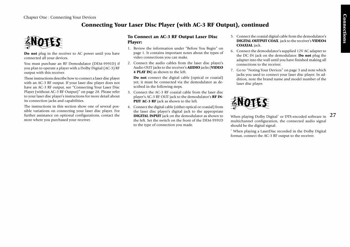
To Connect an AC-3 RF Output Laser DiscPlayer:1. Review the information under “Before You Begin” on
page 1. It contains important notes about the types ofvideo connections you can make.
2. Connect the audio cables from the laser disc player’sAudio OUT jacks to the receiver’s AUDIO jacks (VIDEO4 PLAY IN) as shown to the left.
Do not connect the digital cable (optical or coaxial)yet; it must be connected via the demodulator as de-scribed in the following steps.
3. Connect the AC-3 RF coaxial cable from the laser discplayer’s AC-3 RF OUT jack to the demodulator’s RF IN-PUT AC-3 RF jack as shown to the left.
4. Connect the digital cable (either optical or coaxial) fromthe laser disc player’s digital jack to the appropriateDIGITAL INPUT jack on the demodulator as shown tothe left. Set the switch on the front of the DEM-9991Dto the type of connection you made.
5. Connect the coaxial digital cable from the demodulator’sDIGITAL OUTPUT COAX. jack to the receiver’s VIDEO4COAXIAL jack.
6. Connect the demodulator’s supplied 12V AC adapter tothe DC IN jack on the demodulator. Do not plug theadapter into the wall until you have finished making allconnections to the receiver.
7. Go to “Noting Your Devices” on page 3 and note whichjacks you used to connect your laser disc player. In ad-dition, note the brand name and model number of thelaser disc player.
When playing Dolby Digital* or DTS-encoded software inmultichannel configuration, the connected audio signalshould be the digital signal.* When playing a LaserDisc recorded in the Dolby Digitalformat, connect the AC-3 RF output to the receiver.

28
Chapter One : Connecting Your Devices
Co
nn
ecti
on
s
Connecting Your Laser Disc Player (without AC-3 RF Output)
OPTICAL
VIDEO4
VIDEO3
VIDEO2
CD-R
MD/TAPE1
CD1
DVD
EXT.CONTROLRS-232C
DIGITAL INCOAXIAL
DIGITAL OUT
VIDEO3 IN
COMPONENT VIDEO
DVDIN
MONITOROUT
MONITOROUT
PLAYIN
PLAYIN
PLAYIN
PLAYIN
RECOUT
RECOUT
PLAYIN
S VIDEO VIDEOPRE OUTZONE B PRE OUT
R LFRONTR LSURROUNDR LR L SURROUND BACKSUB WOOFER CENTERVIDEO
R LB A
AUDIO
VIDEO1
VIDEO2
VIDEO3
VIDEO4
DVD FRONT
DVD/6CH
INPUT
SURROUND
CENTER SUBWOOFER
PHONO
CD1
RECOUT
PLAYIN
MD/TAPE1
RECOUT
PLAYIN
CD-R
RECOUT
PLAYIN
CD2/TAPE2
MONITOR
CENTERSPEAKER
(6–16Ω)
SURROUNDSPEAKERS
(6–16Ω)
FRONT SPEAKE(6–16Ω)
ANTENNA
GNDAM
FM 75Ω
SYSTEMCONTROL
SL16 TEXT
REMOTE
TV ON/OFFSENSOR
RELAYCONTROL
IR OUTLCD
IR RECEIVERIN
IR RECEIVERIN
DVD CONTROL
C
R
L
A
DC5V 10mADC12V 20mADC12V 20mA DC12V 20mA
DE-EMPHASISCHANNEL SPACE
R LAUDIO
PR/CR
PB/CB
Y
PR/CR
PB/CB
Y
PR/CR
PB/CB
Y
50 µsAM 9kHzFM 50kHz
75 µsAM 10kHzFM 100kHz
REMOTE
IR OUT LCD
AUDIO OUT
VIDEO OUT
S- VIDEO OUT
DIGITAL OUT OPTICAL or COAXIAL
Remove protective capbefore inserting
Note that video device jacks are linked to specific digitaljacks.
As a result, every digital cable or analog cable should beconnected between jacks having the same name.

29
Chapter One : Connecting Your Devices
Co
nn
ection
s
Connecting Your Laser Disc Player (without AC-3 RF Output), continued
Do not plug in the receiver to AC power until you haveconnected all your devices.
These instructions describe how to connect a laser disc playerwith a PCM Digital Output. If your player has a Dolby Digi-tal (AC-3) RF Out, see “Connecting Your Laser Disc Player(with AC-3 RF Output)” on page 26. This configuration doesnot allow Dolby Digital laser discs to be played. Please re-fer to your laser disc player’s instructions for more detailabout its connection jacks and capabilities.
The instructions in this section show one of several pos-sible variations on connecting your laser disc player. Forfurther assistance on optional configurations, contact thestore where you purchased your receiver.
To Connect a PCM Digital Output LaserDisc Player:1. Review the information under “Before You Begin” on
page 1. It contains important notes about the types ofvideo connections you can make.
2. Connect the audio cables from the laser disc player’sAudio OUT jacks to the receiver’s AUDIO jacks (VIDEO4 PLAY IN) as shown to the left.
3. Connect the video cable from the laser disc player’sVideo OUT jack to the receiver’s VIDEO PLAY IN jackas shown to the left.
Note that the jack sets are linked, even though they arenot adjacent. You must connect all of the cables fromyour laser disc player to a linked jack set. If you connectthe analog cables to VIDEO3 and the digital opticalcable to VIDEO4, your laser disc player will not workcorrectly.
4. Connect the digital cable (either optical or coaxial) fromthe laser disc player’s digital jack to the appropriate digi-tal jack on the receiver as shown to the left. Your laserdisc player supports only one of the digital connectionmethods—do not connect both.
5. Go to “Noting Your Devices” on page 3 and note whichjacks you used to connect your laser disc player. In ad-dition, note the brand name and model number of thelaser disc player.
When playing DTS-encoded software in multichannel con-figuration, the connected audio signal should be the digi-tal signal.

30
Chapter One : Connecting Your Devices
Co
nn
ecti
on
s
Connecting Your Turntable/Record Player
OPTICAL
VIDEO4
VIDEO3
VIDEO2
CD-R
MD/TAPE1
CD1
DVD
EXT.CONTROLRS-232C
DIGITAL INCOAXIAL
DIGITAL OUT
VIDEO3 IN
COMPONENT VIDEO
DVDIN
MONITOROUT
MONITOROUT
PLAYIN
PLAYIN
PLAYIN
PLAYIN
RECOUT
RECOUT
PLAYIN
S VIDEO VIDEOPRE OUTZONE B PRE OUT
R LAUDIO
R LFRONTR LSURROUNDR LR L SURROUND BACKSUB WOOFER CENTERVIDEOB A
VIDEO1
VIDEO2
VIDEO3
VIDEO4
DVD FRONT
DVD/6CH
INPUT
SURROUND
CENTER SUBWOOFER
PHONO
CD1
RECOUT
PLAYIN
MD/TAPE1
RECOUT
PLAYIN
CD-R
RECOUT
PLAYIN
CD2/TAPE2
MONITOR
ANTENNA
GNDAM
FM 75Ω
S
REMOTE
TV ON/OFFSENSOR
RELAYCONTROL
IR OUTLCD
IR RECEIVERIN
IR RECEIVERIN
DVD CONTROL
DC5V 10mADC12V 20mADC12V 20mA DC12V 20mA
R LAUDIO
PR/CR
PB/CB
Y
PR/CR
PB/CB
Y
PR/CR
PB/CB
Y
AF
REMOTE
IR OUT LCD
AUDIO OUT
GND
Do not plug in the receiver to AC power until you haveconnected all your devices.
This section focuses on the connections from your turntable/record player to the KRF-X9995D. Please refer to yourturntable/record player’s instructions for more detail aboutits connection jacks and capabilities.
To Connect a Turntable/Record Player:1. Connect the audio cables from the turntable audio out-
put jacks to the receiver’s PHONO R and L jacks.
2. If your turntable includes a ground cable, connect theground cable to the receiver’s (ground) jack.
3. Go to “Noting Your Devices” on page 3 and note whichjacks you used to connect your turntable. In addition,note the brand name and model number of the turn-table.

31
Chapter One : Connecting Your Devices
Co
nn
ection
s
Connecting a Camcorder or Additional VCR
This section focuses on the connections from yourcamcorder or VCR to the front of the KRF-X9995D. Pleaserefer to your camcorder or VCR’s instructions for more detailabout its connection jacks and capabilities.
These instructions describe how to connect a camcorder orVCR quickly and probably temporarily to the front of thereceiver. If you want a less cluttered and more permanentconnection, see “Can I Connect an Additional VCR Perma-nently?”, below.
To Connect a Camcorder or Additional VCR:Connect the audio and video cables from the camcorder orVCR’s Audio and Video jacks to the receiver’s front paneljacks as shown to the left.
Can I Connect an Additional VCRPermanently?Yes. To do so, follow the instructions under “To Connect aSecondary VCR:” on page 15.
DOOROPEN/CLOSE
VOLUME CONTROL
DOWN UP
S VIDEO VIDEO L - AUDIO - R
CD2/TAPE2MONITOR
CLIPINDICATOR
AV AUX
VIDEO OUT
S-VIDEO OUT
AUDIO OUT
(or additional VCR)

32
Chapter One : Connecting Your Devices
Co
nn
ecti
on
s
SYSTEMCONTROL
SYSTEMCONTROL
SYSTEMCONTROL
SYSTEMCONTROL
What if I Have Several Kenwood Devices (System Control Chaining)?
Connecting system control cords after connecting aKenwood audio component system lets you take advantageof convenient system control operations.
This unit is compatible only with the [SL16] mode. The sys-tem control operation is not available if the unit is con-nected in the [XS8] connection mode.
If your component has the mode select switch, set the con-nected components to the [SL16] mode.
• You can connect the system control cord to either sys-tem control jack of the unit.
• Do this operation after completing all connections. (En-sure that the power plug is not connected.)
System Control connection allows you to:
• See the current status of the selected source device, suchas Play or Stop
• control connected devices via the remote
• switch the receiver’s input automatically to a connecteddevice when you start playback from that device
• synchronize recording a CD automatically when youstart playback from the connected CD player
Receiver
CD Player
MD Recorder orTape Deck
Other [SL 16]compatible device
SYSTEMCONTROLcord
Make sure the units are connected to the correct jacks onthe receiver—for example, no device connected to the CD2/TAPE2 MONITOR jacks can use a system control cable.
Some CD players and cassette decks do not support the SL16system control mode. Do not include these devices in a setof SL16 chained connections.
Do not mix connections of the two modes: if a device doesnot support the mode you are using for chaining, do notconnect that device.
Do not connect system control cables to any device notspecified by Kenwood. Using system control functions witha device that does not support them can damage the device.
Make sure system control plugs are firmly seated in the ap-propriate jacks.

33
Chapter One : Connecting Your Devices
Co
nn
ection
s
Connecting the Antennas
AM Loop Antenna
ANTENNA
GNDAM
FM 75Ω
Your new receiver comes with an AM loop antenna for AMradio reception. To connect the AM antenna:
1. Insert the antenna loop into the base and position theloop.
2. Open the receiver’s antenna terminal levers.
3. Insert the antenna’s wires into the terminal as shownabove.
4. Close the antenna terminal levers to lock the wires inplace.
5. Adjust the antenna loop as necessary to improve recep-tion.
To prevent hum interference, keep the AM antenna wiresaway from speaker wires, AC power cords, the TV chassis,and the receiver.
FM Indoor Antenna
Your new receiver also comes with an FM indoor antennafor FM radio reception. To connect the FM antenna:
1. Attach the antenna sheath to the pole in the center ofthe receiver’s FM antenna jack, as shown above. Whenyou attach the sheath for the first time, you may need toexert quite a bit of pressure.
2. Adjust the antenna as necessary to improve reception.
3. Tack the looped end of the antenna in the location thatprovides the best reception.
ANTENNA
GNDAM
FM 75Ω
FM Outdoor Antenna
ANTENNA
GNDAM
FM 75Ω
Kenwood recommends a permanently installed outdoor FMantenna for best FM reception. To connect an outdoor FMantenna:
1. Connect the antenna wire to a standard, commerciallyavailable antenna adapter as shown above.
2. Connect the adapter to the receiver’s FM antenna jack.
What if I Have Cable Radio?If you have cable radio, contact your cable provider for as-sistance with connecting to the KRF-X9995D.

34
Rem
ote
Set
up
Chapter Two : Setting Up PowerTouch
Chapter Two: Setting Up PowerTouchYour new PowerTouch controls your new receiver and canbe set up to control most components attached to it.PowerTouch appears and functions a little differently fromtraditional remotes. It incorporates sophisticated engineer-ing and design to allow you to simply touch the screen topress buttons and operate controls. You can touch the screenwith your finger or with the stylus stored at the top of thePowerTouch.
Because it can control so many different devices, it presentsa separate set of controls for each device on an LCD screen.Touch an icon on the screen to access further menus or con-trols for devices.
Only devices previously identified and connected to thereceiver will appear as icons on the display screen. If youare “missing” an icon on your display screen, make sureyou have identified the device to PowerTouch. This chapterdescribes identifying devices to PowerTouch.
Installing the BatteriesBefore you can set up any PowerTouch item, you need toinstall batteries.
• The batteries that came with your new PowerTouch areintended for you to use for an operation check—theymay not last as long as ordinary batteries. We recom-mend replacing them with alkaline batteries for nor-mal use.
To install the batteries:
1. Press down and back on the battery cover to remove it.
2. Insert six AA (LR6) batteries as shown:
3. Close the cover.
If you use PowerTouch outside of it’s range (see “How isPowerTouch Powered?” on page 5 of the Users’ Guide)PowerTouch’s display may show incorrect information.
When your batteries begin to run low, PowerTouch displaysa Low Battery message. Clear the message by touching check
mark icon ( ) and replace all batteries as described here.
Maximize the life of your batteries by turning the Backlightoff if you are not trying to use PowerTouch in the dark. Formore information on the Backlight, see page 73 of the Us-ers’ Guide.
This chapter contains the following sections:
Installing the Batteries page 34
Calibrating the Touch Screen page 35
Selecting the Model Type page 35
Navigating PowerTouch Interface page 36
Setting Up Speakers page 37
Identifying Devices For PowerTouch Control page 40
Storing Radio Stations in Memory page 41
If you cannot see anything on the screen after replacingbatteries, try to adjust the screen contrast. See 74 page ofthe Users’ Guide.
(for U.K. only)
If you are installing the receiver in a home entertainmentcloset, a simpler installation option is to use the ExternalInfrared Receiver. For more information, see “Connectingthe External Infrared Receivers (for U.K. only)” on page 51.
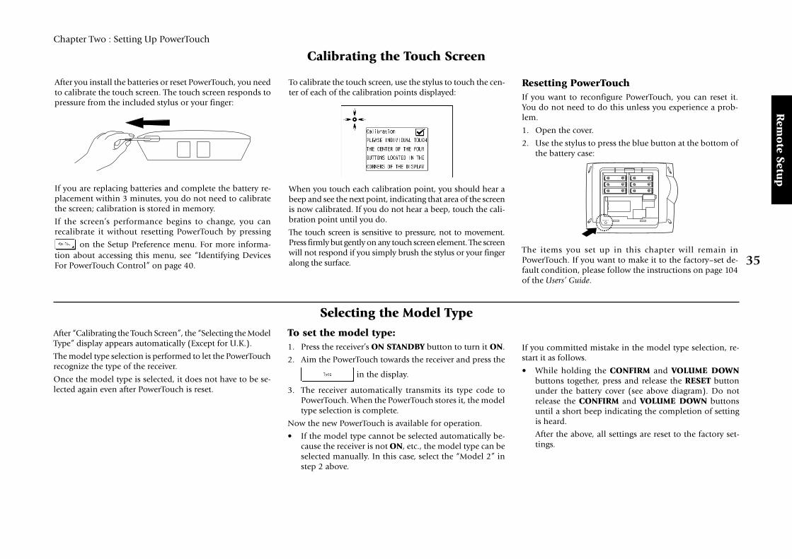
35
Rem
ote Setu
p
Chapter Two : Setting Up PowerTouch
Calibrating the Touch Screen
After you install the batteries or reset PowerTouch, you needto calibrate the touch screen. The touch screen responds topressure from the included stylus or your finger:
If you are replacing batteries and complete the battery re-placement within 3 minutes, you do not need to calibratethe screen; calibration is stored in memory.
If the screen’s performance begins to change, you canrecalibrate it without resetting PowerTouch by pressing
on the Setup Preference menu. For more informa-tion about accessing this menu, see “Identifying DevicesFor PowerTouch Control” on page 40.
To calibrate the touch screen, use the stylus to touch the cen-ter of each of the calibration points displayed:
When you touch each calibration point, you should hear abeep and see the next point, indicating that area of the screenis now calibrated. If you do not hear a beep, touch the cali-bration point until you do.
The touch screen is sensitive to pressure, not to movement.Press firmly but gently on any touch screen element. The screenwill not respond if you simply brush the stylus or your fingeralong the surface.
Resetting PowerTouchIf you want to reconfigure PowerTouch, you can reset it.You do not need to do this unless you experience a prob-lem.
1. Open the cover.
2. Use the stylus to press the blue button at the bottom ofthe battery case:
The items you set up in this chapter will remain inPowerTouch. If you want to make it to the factory–set de-fault condition, please follow the instructions on page 104of the Users’ Guide.
Selecting the Model Type
If you committed mistake in the model type selection, re-start it as follows.
• While holding the CONFIRM and VOLUME DOWNbuttons together, press and release the RESET buttonunder the battery cover (see above diagram). Do notrelease the CONFIRM and VOLUME DOWN buttonsuntil a short beep indicating the completion of settingis heard.
After the above, all settings are reset to the factory set-tings.
After “Calibrating the Touch Screen”, the “Selecting the ModelType” display appears automatically (Except for U.K.).
The model type selection is performed to let the PowerTouchrecognize the type of the receiver.
Once the model type is selected, it does not have to be se-lected again even after PowerTouch is reset.
To set the model type:1. Press the receiver’s ON STANDBY button to turn it ON.
2. Aim the PowerTouch towards the receiver and press the
in the display.
3. The receiver automatically transmits its type code toPowerTouch. When the PowerTouch stores it, the modeltype selection is complete.
Now the new PowerTouch is available for operation.
• If the model type cannot be selected automatically be-cause the receiver is not ON, etc., the model type can beselected manually. In this case, select the “Model 2” instep 2 above.
RESET

36
Rem
ote
Set
up
Chapter Two : Setting Up PowerTouch
Navigating PowerTouch Interface
For the rest of this chapter, you will be using the varioussettings on the Setup menu. The Setup menu includes thefollowing settings and their subsettings:
• Preference, which contains the following:
• IR (“Identifying Devices For PowerTouch Control”on page 40)
This menu setting allows you to identify your con-nected devices to PowerTouch.
• Input (See the KRF-X9995D Users’ Guide).
• Multi Zone (“Chapter Four: Setting Up MultipleZones” on page 48).
This menu setting allows you to activate dual-zonecontrol, and to select which zone you want to con-trol with PowerTouch.
• CopyThis menu will allow you to copy all the settingsstored in your PowerTouch to a second PowerTouch.Instructions are included in separately soldPowerTouch package. (Only for some areas)
• Surround (“Setting Up Speakers” on page 37)
These menu settings allow you to set up speakers andsubwoofer, set the distance from your speakers to thelistening area, determine speaker levels, and set the sur-round speaker type. The Next button on each screentakes you to the next group of settings (i.e., pressing Nextat SP Selection takes you to SP Distance without havingto go back to the menu).
• Macro (See the KRF-X9995D Users’ Guide)This menu setting allows you to create custom macrosthat perform several operations (such as turning a de-vice on, changing the receiver’s input, and changing aTV station) with a single touch.
• CustomizeThis menu setting allows you to configure yourPowerTouch so that the screen buttons are easiest foruse according to your liking.
With this menu, you can change, copy, cut, paste and/or delete the names, positions and sizes of the buttonsdisplayed on the screen.
To change the time until the screen goes out:
In order to reduce the battery consumption, the PowerTouchhas been designed so that the screen goes out when there isno operation for a given time. This time can be changed.
1 Touch (SETUP) to call up the SETUP screen.
2 Touch to call up the Standby Time setting screen.
3 Touch or to set the desired time. The time
until the screen goes out can be changed to any valuefrom 5 to 30 seconds.
4 Touch to return to the original screen.
The PowerTouch has four basic menus as shown below:
HOME1 HOME2
SETUP EDIT
There are two ways for moving across these four basic menus:
• Touch character or icon “HOME1”,“HOME2”, “SETUP” or “EDIT” in the screenusing a stylus or your finger.
• Touch the desired icon in the quick accessmenu on the left of the touch-screen.
Quick Access menu
HOME1 HOME2 SETUP EDIT
: Touch this to initiate the Customize mode(see page 43).
: Touch this to return to the normal operationmode from the Customize mode (see page 43).

37
Rem
ote Setu
p
Chapter Two : Setting Up PowerTouch
Setting Up Speakers
Before you can begin using the receiver to control your homeentertainment system, you must set up PowerTouch to op-erate your speakers effectively. There are four areas of speakersetup:
• SP Selection• SP Distance• SP Level• Bass Peak LevelYou can set up your speakers in the order presented here(via the Next button) or individually, selecting each optionfrom the Surround menu.
The receiver must be on, speakers must be connected, andSpeaker A on the front panel must be turned on before youcan set up speakers.
SBL/SBR (Surround back speakers) : The SBL/SBR speak-ers are required to reproduce the 6.1-channel signals. Placethem on the left and right behind the listening position andat a height slightly higher than the SL/SR speakers.
To begin setting up speakers:
1. Touch (SETUP) on the Quick Access menu to accessthe Setup menu:
2. Touch on the Setup settings.
SP Selection
1. Touch on the Setup Surround menu to open
the Speaker Selection menu.
2. Kenwood provides two ways to set up your speakers:
Quick Setup: Use this method for a simplified setupwhere you identify whether a speaker is present and letthe receiver automatically determine the appropriatespeaker settings.
FL FRC
SW
SL SR
SBL SBR
Speaker Placement
FL/FR (Front speakers) : Place to the front left and rightof the listening position. Front speakers are required for allsurround modes.
C (Center speaker) : Place front and center. This speakerstabilizes the sound image and helps recreate sound motion.
SW (Subwoofer) : Reproduces powerful deep bass sounds.
SL/SR (Surround speakers) : Place to the direct left andright, or slightly behind, the listening position at evenheights, approximately 1 meter above the ears of the listen-ers.
1 Aim PowerTouch at the receiver. If the speaker ispresent, touch the speaker button until “Yes” appearsin the button. (SW=subwoofer, C=center,SL=surround left, SR=surround right, SBL=surroundback left and SBR=surround back right)
If you selected Yes for the subwoofer, all of the bassbelow 80Hz is removed from other speakers in yoursystem and is sent to the subwoofer in all listeningmodes. This improves your speakers’ power handlingand reduces overall distortion.
2 Touch to save your settings.
3 Touch to move to the next speaker setting or
touch to return to the Setup Surround menu.
YesNo No
Yes
Centerspeaker
No
YesNo
Surroundspeakers
Surround back speakers
YesNo
Subwoofer
Speaker combinations that can be selected with QuickSetup
An example of installation is shown here.Use this figure as a reference for installing the system ac-cording to the types of your speakers and conditions of yourlistening room.

38
Rem
ote
Set
up
Chapter Two : Setting Up PowerTouch
Custom setup: Use this method for a more customizedsetup where you determine more of the speaker settings,such as the bandwidth of the sound sent to each speaker.Custom setup configures the following: SW=subwoofer,L=front left, R=front right, C=center, SL=surround left,SR=surround right, SBL=surround back left andSBR=surround back right.
1 Touch on the Speaker Selection menu:
2 Aim PowerTouch at the receiver and touch the speakerbutton until the correct setting appears (see below).
The front left and right buttons, the surround leftand right buttons and the surround back left andright buttons are linked; if you touch one, you changethe settings for both.
• Off means you are not using the speaker. (Not avail-able for front speakers). If no subwoofer is connected,all bass below 80Hz is sent to front left and rightspeakers.
• On means that you are using the speaker. (Only avail-able for subwoofer).
• Select Nml (= Normal/THX) if the speaker is not ca-pable of producing clean, deep bass energy at outputlevels that match those produced by a typical poweredsubwoofer. All bass below 80Hz in that channel is re-moved from that speaker and is sent to the subwoofer(or sent to the front speakers if subwoofer is set to off)in all listening modes. Most speakers should be consid-ered Nml. If no subwoofer is connected, that signal issent to front left and right speakers.
If you have THX certified speakers, select the Nml set-ting.
• Select Lrg (= Large) if the speaker is capable of pro-ducing clean, deep bass energy at output levels thatmatch those produced by a typical poweredsubwoofer. All bass below 80Hz in that channel isleft in that speaker in all listening modes.
The subwoofer may not output audio depending onthe setups of the input signal, speakers and listen mode.
3 If you set your left and right front speakers to Lrgand want to send bass to the subwoofer in all Listen
modes, touch until “On” appears above the
button. SW Re-Mix mixes some of the bass compo-nents in the signals for all the speakers and outputit to the subwoofer.
The SW Re-Mix ON/OFF is defeated when you setyour front speakers to Nml.
4 Touch to save your settings.
5 Touch to move to the next speaker setting or
touch to return to the Setup Surround menu.
When activating the THX operation, it is recommended toset SW Re-Mix OFF so that the THX operation can matchcorrectly the human sense of audition.
SP Distance1. Measure the distance from each speaker to the seat you
most often use and note it below:
Lrg
Lrg
Nml
Frontspeakers
NmlLrgOff
NmlLrgOff
NmlLrgOff
NmlOff
Centerspeaker
Off
Nml
Off
Nml
Off
Nml
Off
Nml
Surroundspeakers
Off
NmlLrgOff
Off
NmlLrgOff
Off
NmlLrgOff
Off
NmlOff
Surround back speakers
Off
On
Subwoofer
Lrg
Lrg
Lrg
2. If you are not already there, touch on the
Setup Surround menu to open the Speaker Distancemenu:
3. Touch or to set the distance for the front
left speaker.
4. Touch or to select the next speaker.
5. Repeat steps 3 and 4 for each speaker.
6. Touch to move to the next speaker setting or touch
to return to the Setup Surround menu.
Front left
Center
Front right
Surround right
Surround back right
Surround back left
Surround left
Subwoofer
Speaker Distance (ft or m)
Speaker combinations that can be selected with Custom Setup
Nml : Normal/THX Lrg : Large Off : Do not use.

39
Rem
ote Setu
p
Chapter Two : Setting Up PowerTouch
(Do not be concerned with the volume number read-out on the Level display—this is for reference purposesonly. Use your ears to determine if the two speakers areplaying at the same volume).
8. Repeat steps 6 and 7 until all the system’s speakers (exceptthe subwoofer) play at the same volume.
9. To confirm the volume levels, touch until the Test
Tone display reads “Auto”. The test noise will automati-cally cycle between all of the speakers. Fine-tune the chan-nel levels as necessary.
10. When all the channels sound like they’re the same vol-ume, you’ve balanced your system.
11. To turn off the test noise, touch until the Test Tone
display reads “Off”.
Setting the Subwoofer Level: Because of the way hu-mans hear, the test noise the Speaker Level menu sendsthrough the subwoofer will not sound as loud as it re-ally is. (The Speaker Level menu subwoofer test noise isdesigned to be used with a sound pressure level meterfor balancing.)
Because of this, you cannot use that test noise to prop-erly calibrate the level of your subwoofer by ear. To setthe subwoofer level, listen to familiar music or filmsthat have strong bass content and adjust the subwooferlevel until it sounds balanced with the rest of the speak-ers.
12. Touch to move to the next speaker setting or touch
to return to the Setup Surround menu.
To obtain accurate output levels
To obtain accurate output levels, it is recommended to usea handheld Sound Pressure Level (SPL) meter. Readingsshould be taken from your actual listening position andadjust the level of each speaker to 75 dB SPL (C-weighted/slow meter mode).
SP LevelIn this step you will use your ears to balance the volume levelof all the system’s speakers except the subwoofer for your roomand listening position. (To set the subwoofer level, see “Set-ting the Subwoofer Level” on this page.) When all the speak-ers are set at the same volume level, your system will create amore realistic, spacious surround sound environment.
It is recommended to use a SPL meter to adjust the speakerlevels accurately. (See “To obtain accurate output levels” onthis page)
When setting the speaker levels, be careful against thehigh-level test tone that is produced.
1. Eliminate as many external noise sources as possible.
2. Sit in the place where you and your guests are most likelyto sit while watching movies or listening to music.
3. If you are not already there, touch on the
Setup Surround menu to open the Speaker Level menu:
4. Touch until the Test Tone display reads “Manu”.
5. Test noise will play from the front left speaker. Care-fully listen to the volume level of the noise.
6. Touch or to select the next speaker.
7. Carefully listen to the volume level of the test noise. Ifthe noise is a different volume than the noise from the
front left speaker, use or to adjust the vol-
ume so that the volume matches the volume from thefront left speaker.
Bass Peak LevelIn this step, you set the maximum volume of the bass soundso that the speaker sounds are not distorted even whenexcessively-large bass signal is input. When playback isperformed hereafter, the bass sound is regulated automaticallyso as not to exceed the level set here.
1. Touch on the Setup Surround setting menu.
Or touch on the Speaker Level menu.
2. Touch on the Bass Peak Level setting menu.
The test tone is output. (displayed “-30 dB”)
The level of the test tone is not affected by the currentsetting of the volume control.
3. Touch the or to adjust the speaker level at
a level just before the audio starts to be distorted.
4. Touch the to complete the setting.
5. Touch the to return to the Setup Surround menu.
Do not output the test tone for a long period while thespeaker audio is distorted.

40
Rem
ote
Set
up
Chapter Two : Setting Up PowerTouch
Identifying Devices For PowerTouch Control
Once your speakers are set up and configured, you mustidentify your component devices to PowerTouch.PowerTouch can be set up to control any device: if the de-vice code is not already part of PowerTouch’s extensive li-brary, you can use the Learn feature to teach the device’scommands to PowerTouch. You can also use this Learn func-tion to expand the control capabilities of existing codes.For more information, see “To Customize the PowerTouchScreen” on page 43.
How Do I Identify Devices?1. Make sure you have installed batteries and chosen a
model type.
2. Touch (SETUP) on the Quick Access menu toaccess the Setup menu.
3. Touch on the Setup menu to access the IRSetup menu:
4. Refer to “Noting Your Devices” on page 3 where younoted which device was connected to which jack set.
5. Touch to open the list of available jack sets:
• CD1
• CD2/TAPE2
• MD/TAPE1
• CD-R
• VIDEO1 through VIDEO4
• DVD
• AV AUX
• TV1 and TV2 (these allow PowerTouch to controlyour TV or cable tuner, even if it isn’t connected toone of the receiver’s input jack sets).
Touch the jack name on the list.
6. Touch to select the type of device you haveconnected to the jack set.
7. Touch to select the device’s brand.
8. Touch . You can now choose from a list ofall the codes available for the device. Touch the first codeon the list.
• If the devices are connected with a system controlcable, be sure to select the code preceded by “Sys-”or “System”. This instructs PowerTouch to send allcommands for the device to the receiver, which willcontrol the device via the system control cable.
• If you have a Kenwood Dual-Play 200-Disc CDChanger, you will need to set both CD1 and CD2/TAPE2 to the correct code for this device (“Sys-Mega”).
9. Touch . This instructs PowerTouch to send a
“power” test signal to the device. If your device turnson, the code you entered was correct. If it does not turnon, try the next code in the list. Continue until one ofthe codes works. If none of the codes work, see “To Cus-tomize the PowerTouch Screen” on page 43.
If you enter the code preceded by “Sys-” or “System” onstep 8, skip this step.
10. When you have a code that works, touch . Check
off that device on your list.
Repeat steps 5 through 10 until you are finished identifyingdevices to PowerTouch. When you are done, turn to “HowDo I Operate Devices?” on page 35 of the Users’ Guide andnote which icon corresponds to which connected device.
How Do I Replace a Setup Code with a NewOne?If you purchase a new device to replace an existing device,you will need to identify the new device to PowerTouch. Todo so:
1. Connect the device as described in the appropriate sectionof Chapter One of this manual.
2. Follow the steps under “How Do I Identify Devices?” onthis page. When you touch, it will replace the other code.
How Do I Delete Setup Codes?If you disconnect a device and do not plan to replace it,you may want to delete the setup code from PowerTouch.To do so:
1. Follow the steps under “How Do I Identify Devices?” onthis page to select a jack set.
2. Touch . Scroll to the device “Nothing” thentouch it. That device is no longer controlled byPowerTouch.
Example of Input button displayWhen a device is identified, its icon will be displayed amongthe Input buttons. The TUNER and PHONO icons are dis-played by default.
Example with the CD1 device button:
Icon of identified device (CD)
This mark indicates that pressing theicon button of an identified device(CD) displays the next screen (the con-trol screen for the device).

41
Rem
ote Setu
p
Chapter Two : Setting Up PowerTouch
Your new PowerTouch provides two ways to store radio sta-tions:
• Manual Memory, which allows you to enter and storespecific stations.
• RDS Automatic Memory ( for U.K. only), which searchesfor stations broadcasting an RDS signal and automati-cally stores them in the first available storage button.
There are 40 preset storage buttons available.
If you have a KRF-X9995D for U.K., search for and storeRDS stations first, then set stations manually. The searchfunction automatically assigns RDS stations to the firststorage button, overwriting any stations already stored there.
You can overwrite RDS stations with manually stored sta-tions.
Storing RDS Stations Automatically(for U.K. only)
1. Touch (HOME1) on the Quick Access menu to ac-cess the HOME1 menu:
2. Touch on the HOME1 menu to access the Tuner
controls:
3. Touch to choose FM.
4. Touch .
5. Touch . The receiver locates and stores any FM sta-tions broadcasting an RDS signal. This process can takea few minutes to complete; please be patient. While thereceiver is searching, “AUTO MEMORY” display blinks.
RDS stations are stored in the order they are found, up to40 stations. If the search finds fewer than 40 stations, thereceiver may automatically store other FM stations in theopen storage buttons.
If you are repeating the RDS search, any existing preset sta-tions (whether automatically or manually stored) will bereplaced by the results of the new search.
Storing Radio Stations in Memory (optional)
Storing RDS Station Name (PS Read)(for U.K. only)
• To execute PS Read, it is required to finish the automemory operation in advance.
1. Touch (HOME1) on the Quick Access menu to ac-cess the HOME1 menu:
2. Touch on the HOME1 menu to access the Tuner
controls:

42
Rem
ote
Set
up
Chapter Two : Setting Up PowerTouch
3. Touch .
4. Touch .
5. Confirm the station name list and touch if it is
OK. If you do not want to finalize, touch to return tothe previous screen.
The station name are written in the preset channel list.
Storing Stations Manually
1. Touch (HOME1) on the Quick Access menu to ac-cess the HOME1 menu:
2. Touch on the HOME1 menu to access the Tunercontrols:
3. Touch to choose the receiving band.
4. Touch to switch between Auto tuning and Manual
tuning. Select Manual if you experience interference dueto weak radio signals.
5. Choose the station you want to store using one of thefollowing methods:
• Touch or until the station’s broadcast fre-quency appears.
• Touch and enter the broadcast frequencyusing the 10key pad. (e.g.; To select FM 87.5 MHz,
enter 8, 7, 5, 0, and )
Touch (check icon) to return to the TUNER controlmenu.
6. Touch .
7. Touch a storage button. Use or to access morestorage buttons.
If you choose a storage button that already has a stationassigned, the new station will replace the previously-stored station.
8. Touch to tune to the newly saved station and re-turn to the Tuner controls.
9. Repeat steps 3 through 8 for each station you want to store.
Name input of the preset station.
Touch to enter a name for the station in the TUNERmenu:
• Use the stylus to select characters from the keyboard.
• Touch to access other characters.
• Touch to insert a space.
• Touch or to move back and forth between thecharacters.
• Touch (backspace) to clear the last character you en-tered. Touch (all clear) to delete all the charactersin the line.
• Touch to save your title.

43
Rem
ote Setu
p
Chapter Two : Setting Up PowerTouch
To Customize the PowerTouch Screen
The configuration of the items in the PowerTouch screensuch as the buttons can be customized so that they are easyto use according to your liking.
1. Name ( ) : The name of the selected item can bechanged.
2. Size ( ) : The size of the selected item can bechanged.
3. Move ( ) : The selected item can be moved.
4. Cut ( ) : The selected item can be cut. The cutitem can be pasted in another position.
5. Copy ( ) : The selected item can be copied andpasted in another position.
6. Paste ( ) : The cut or copied item can be pasted inthe specified position.
7. Delete ( ) : The selected item can be deleted.
8. Learn ( ) : A function can be programmed in an itemon the touch panel or in a hardware key.
9. Gallery ( ) : An item stored in a gallery can be pastedin a desired position.
10. Jump ( ) : When the jump mode is activated dur-ing customization, the buttons whichare capable of switching the screen canbe used for their original functions.
For example, if you touch the iconto activate the jump mode during
customization, the button be-
comes the button for jumping to theTUNER screen.
11. Default ( ) : The screen configuration can be reset tothe default.
12. Undo ( ): Returns a customized operation to thecondition before customization.
Changing the Name1. Touch the icon in the menu you want to customize.
(The customization cannot be initiated in screens wherethe icon is grayed out.)
2. Customization icons are displayed, with the icon
highlighted to indicate the Name mode. If the iconis not highlighted, touch it so that it is highlighted.
3. Touch the item you want to rename. The keyboard screenwill appear.
The character entry space on the upper part of the key-board shows the name currently given to the icon. Tochange the name, delete it with the BS (backspace) but-ton and enter a new name.
Touch the displays other characters. For detailson the keyboard operation, see page 8 of the User's Guide.
4. Touch the to enter the name.
5. To continue customization, touch another item then pro-ceed to the next operation.
Touch the icon to exit from customization.
Changing the Item Size1. Touch the icon in the menu you want to customize.
(The customization cannot be initiated in screens wherethe icon is grayed out.)
2. When the customization icons are displayed, touch the
icon so that it is highlighted (Size mode).
3. Touch the item you want to resize. The selected item willblink.
4. Change the item size using the joystick.
Customization icons
Touch this icon to exit from customizationand return to the normal mode.
ENTER
To increase the height
To decrease the height
To increasethe width
To decreasethe width
The size is changed withrespect to this point.
Example of Resizing ofMD/TAPE1
MD/TAPE1

44
Rem
ote
Set
up
Chapter Two : Setting Up PowerTouch
Moving an Item1. Touch the icon in the menu you want to customize.
(The customization cannot be initiated in screens wherethe icon is grayed out.)
2. When the customization icons are displayed, touch the
icon so that it is highlighted (Move mode).
3. Touch the item you want to move. The selected item willblink.
An item cannot be moved in a position where it is over-lapped with another item or outside the customizable area.
4. To continue customization, touch another item thenproceed to the next operation.
Touch the icon to exit from customization.
Cutting an Item1. Touch the icon in the menu you want to customize.
(The customization cannot be initiated in screens wherethe icon is grayed out.)
2. When the customization icons are displayed, touch the
icon so that it is highlighted (Cut mode).
3. Touch the item you want to cut. The selected item willbe cut now.
The cut item can be pasted in another position by usingthe Paste function.
Copying an Item1. Touch the icon in the menu you want to customize.
(The customization cannot be initiated in screens wherethe icon is grayed out.)
2. When the customization icons are displayed, touch the
icon so that it is highlighted (Copy mode).
ENTER
To move upward
To move downward
To moverightward
To moveleftward
3. Touch the item you want to copy. The selected item willbe copied into memory.
4. Paste the copied item in the desired position by usingthe Paste function.
The copied item cannot be pasted in a position where itis overlapped with another item or outside thecustomizable area.
Pasting an Item1. Cut or copy the desired item.
2. When the customization icons are displayed, touch the
icon so that it is highlighted (Paste mode).
3. Paste the copied item in the desired position by usingthe Paste function.
The copied item cannot be pasted in a position where itis overlapped with another item or outside thecustomizable area.
Deleting an Item1. Touch the icon in the menu you want to customize.
(The customization cannot be initiated in screens wherethe icon is grayed out.)
2. When the customization icons are displayed, touch the
icon so that it is highlighted (Delete mode).
3. Touch the item you want to delete. The selected itemwill be deleted now.
Selecting an Item in the Gallery and Pastingit in the Screen1. Touch the icon in the menu you want to customize.
(The customization cannot be initiated in screens wherethe icon is grayed out.)
2. When the customization icons are displayed, touch the
icon.
Press the to view another gallery display.
3. Touch the item you want to copy. The previous menu isdisplayed.
4. Touch the desired position to paste the selected itemthere. The selected item cannot be pasted in a positionwhere it is overlapped with another item or outside thecustomizable area. If the item you select is a selectoritem (input selector button such as "Tuner" or "CD"), itcan be pasted only in the HOME1 or HOME2 screen.
5. If required, program the desired function in the buttonby using the Learn function.
Programming a Function in a Button (Learn)1. Touch the icon in the menu you want to customize.
(The customization cannot be initiated in screens wherethe icon is grayed out.)
2. When the customization icons are displayed, touch the
icon so that it is highlighted (Learn mode).
3. Select the item in which you want to program the desiredfunction. The buttons which can learn functions are notonly those displayed on the screen but also include theMute button, Volume up/down buttons, On/Standbybutton and Joystick. However, at the menu screen ofHOME1 and HOME2, the Mute button, the Volume up/down buttons, and the On/Standby button can notlearn any functions.
4. Aim the device’s remote at PowerTouch and press andhold the button on the device’s remote that correspondsto the command you want PowerTouch to learn:
This may take a few seconds; do not move PowerTouchor the device’s remote until PowerTouch displays theFunction Change menu again.

45
Rem
ote Setu
p
Chapter Two : Setting Up PowerTouch
BACKLIGHT
• “Complete” is displayed when learning completessuccessfully.
• “Error” is displayed when it failed.
Be sure to use the device’s original remote. PowerTouchwill not learn commands from other universal remotes.
Depending on the remote control unit, "Learn" may not bepossible.
Resetting to Default1. Touch the icon in the menu you want to customize.
(The customization cannot be initiated in screens wherethe icon is grayed out.)
2. When the customization icons are displayed, touch the
icon. The screen configuration reset to the default.
Switching the Customized Screen to another(Jump)When the jump mode is activated during customization,the buttons which are capable of switching the screen canbe used for their original functions.
1. Touch the icon during customization.
The icon is highlighted to indicate the Jump mode.
In the Jump mode, the buttons which are capable ofswitching the screen (such as "Tuner" and "CD") can beused for their original functions.
2. Touch the icon again to return to customization.
To Undo the Last Operation performed
Touch the icon immediately after performing the op-eration that you want to undo. The operation will be can-celed (undo).
Locking Customization Results with a PasswordCustomization by other persons than you can be protectedby setting a password.
To lock customization:
1. Touch (SETUP) on the Quick Access menu to access
the Setup menu.
2. Touch .
3. Touch .
4. Enter a password and touch the .
5. When the Enter Password screen is displayed for the sec-ond time, enter the same password as step 4 again andtouch the .
6. Touch to return to the original screen.
To unlock customization:
1. Touch (SETUP) on the Quick Access menu to access
the Setup menu.
2. Touch .
3. Touch .
4. Enter a password and touch the .
The customization will be unlocked.
5. Touch to return to the original screen.
10 cm (4 inches)

Rec
eive
r Se
tup
Chapter Tree: Setting Up on the Receiver
46
Chapter Tree: Setting Up on the ReceiverIt is possible to set up the speakers on the receiver mainunit.
However, some of the setting items such as the controlleddevice registration should be set on the PowerTouch. Ifsetup is made on the PowerTouch, it is not necessary torepeat any setup on the receiver side.
Therefore, it is recommended to perform setup on thePowerTouch. This chapter describes the setup on the receiveronly as an alternative method in case the setup is not madeon the PowerTouch.
Do not operate the PowerTouch during the receiver setup.
Preparation for setupMost of the receiver control buttons are accommodatedinside the panel door. Make the following preparation forsetup on the receiver.
1. Plug the power cord into a household power outlet.
2. Press the POWER switch to supply the main power. Thereceiver now enters the STANDBY mode (in which re-mote control is available). Then press the ON/STANDBYbutton to turn the receiver ON.
3. Open the panel door.
Panel door
Speaker Setup1. Selecting the speakers
Selecting the SUBWOOFER:
1 Press the SET UP button (SOUND button) insidethe panel door until “SUBWOOFER OFF (or ON)”message appears on the display ( for more than 2seconds ).
2 Press the MULTI CONTROL (fi/%) button to selectON (when a subwoofer is used) or OFF (when not).
Selecting the FRONT speakers:
3 Press the SET UP button to display “FRONT NML/THX (or FRONT LARGE)”.
4 Press the MULTI CONTROL (fi/%) button to selectFRONT LARGE (large-sized speakers) or NML/THX(normal-sized speakers).
If the SUBWOOFER is set to OFF, the FRONT speak-ers are set automatically to LARGE and the CENTERspeaker selection display appears automatically.
Selecting the CENTER speaker:
5 Press the SET UP button to display “CENTER NML/THX (or LARGE or OFF)”.
6 Press the MULTI CONTROL (fi/%) button to selectCENTER LARGE (large-sized speaker), NML/THX(normal-sized speaker) or OFF (no center speaker).
If the FRONT is set to NML/THX, the CENTERspeaker can be set to only either NML/THX or OFF.
Selecting the SURROUND speakers:
7 Press the SET UP button to display “SURR NML/
THX (or LARGE or OFF)”.
8 Press the MULTI CONTROL (fi/%) button to selectSURR LARGE (large-sized speakers), NML/THX(normal-sized speakers) or OFF (no surroundspeaker).
When the FRONT is set to NML/THX, the SUR-ROUND speakers can be set to only either NML/THXor OFF.
When SURROUND OFF is selected, SURROUNDBACK is set automatically to OFF and the SW Re-Mix setting menu is displayed.
If the SUBWOOFER is set to OFF, selecting SW RE-MIX step will be skipped.
Selecting the SURROUND BACK speakers:
9 Press the SET UP button to display “S.BACK NML/THX (or LARGE or OFF)”.
0 Press the MULTI CONTROL (fi/%) button to selectS. BACK LARGE (large-sized speakers), NML/THX(normal-sized or THX speakers) or OFF (no surroundspeaker).
When the FRONT is set to NML/THX, the SUR-ROUND BACK speakers can be set to only eitherNML/THX or OFF.
Press the DOOR OPEN/CLOSE button to openthe panel door. To closeit, press the button again.
A SPEAKERS B INPUTMODE
CD 2/TAPE 2MONITOR
LISTENMODE THX
SET UPDISPLAY
SOUNDMULTI
CONTROLfi % P.CALL MEMORY AUTO BANDfi %
Button layout

Receiver Setu
p
Chapter Tree: Setting Up on the Receiver
47
Selecting SW RE-MIX:
- Press the SET UP button to display “SW-REMIX OFF(or ON)”. If the SUBWOOFER is set to OFF, select-ing SW RE-MIX step will be skipped.
= Press the MULTI CONTROL (fi/%) button to selectON or OFF.
~ Press the SET UP button to proceed to “Adjustingthe speaker volumes” below. To exit from setting,press the SET UP button repeatedly until “SETUPFIXED” is displayed.
For details on the SW RE-MIX and the selection ofspeakers, please see page 38.
2. Adjusting the speaker volumes
Adjust the volume balance between the speakers in the sys-tem by actually listening to them. See page 39 for details.
1 Minimize external noise in the listening room.
2 Position yourself in a place where you usually listento music or view video.
3 Perform operation in step ~ of procedure 1 above.
"TEST TONE OFF" is displayed.
4 Press the MULTI CONTROL (fi/%) button to selectON, then press the SET UP button.
When setting the speaker levels, be carefulagainst the high-level test tone that is produced.
The speaker volume adjustment display appears andtest noise is generated from the front left speaker (“L0 dB” displayed). Listen to the volume of the noisecarefully.
5 When the test noise moves to the center speaker and“C 0 dB” is displayed, adjust the volume to the samelevel as the front left speaker by pressing the MULTICONTROL (fi/%) button.
6 Similarly, adjust the volumes of the “R” (front right),“SR” (surround right), “SBR” (surround back right),“SBL” (surround back left) and “SL” (surround left)speakers.
Do not adjust the “SW” (Subwoofer) volume usingthe test noise. It should be adjusted while listeningto ordinary music.
7 Press the SET UP button to display “BASS PEAKOFF”
8 Press the MULTI CONTROL (fi or %) button, thendisplayed “-30 dB”.
The test noise is output. Press the MULTI CONTROL(fi/%) button to set its level to a level just before thespeaker sound starts to be distorted.
9 Press the SET UP button to proceed to “Setting thespeaker distances” below. To exit from setting pressthe SET UP button repeatedly until “SETUP FIXED”is displayed.
3. Setting the speaker distances
Measure the distance between each speaker and the listen-ing position you frequently use. See page 38 for details.
1 After the operation of 9 in procedure 2 above, thespeaker distance setting display appears.
2 When “L 3.0m/10ft” is displayed, correct the dis-tance of the front left speaker from you using theMULTI CONTROL (fi/%) button.
3 Press SET UP button to display “C 3.0m/10ft” andcorrect the distance of the center speaker from youusing the MULTI CONTROL (fi/%) button.
4 Similarly, set the distances of the “R” (front right),“SR” (surround right), “SBR” (surround back right),“SBL” (surround back left), “SL” (surround left) and“SW” (Subwoofer) speakers.
5 Press the SET UP button repeatedly until “SETUPFIXED” is displayed.
Storing Radio Stations in Memory(optional)Radio stations can be preset in the memory in the receiverand recalled by a one-touch operation.
The memory in the receiver cannot store the station names.To store the station names, use the PowerTouch. (For de-tails, see “Storing Radio Stations in Memory (optional)” onpage 41.)
Storing RDS Stations Automatically (for U.K. only):
1. Press the INPUT SELECTOR (¤ or ‹) button to se-lect the Tuner input.
2. Press the BAND button to select the FM band.
3. Press and hold the MEMORY button for more than 2seconds. The receiver locates and stores any FM stationsbroadcasting an RDS signal. This process can take a fewminutes to complete; please be patient. While the re-ceiver is searching, “AUTO MEMORY” display blinks.
Storing Stations Manually:
1. Press the INPUT SELECTOR (¤ or ‹) button to se-lect the Tuner input.
2. Press the BAND button to choose the receiving band.
3. Press the AUTO button to select AUTO TUNING orMANUAL TUNING.
4. Press the MULTI CONTROL (fi/%) button to tune thestation you want to store.
5. Press the MEMORY button.
6. Press the P.CALL (fi/%) button to display the desiredpreset number.
7. Press the MEMORY button again to complete the pre-setting.
8. To preset other stations, repeat steps 2 to 7 for eachstation you want to store.
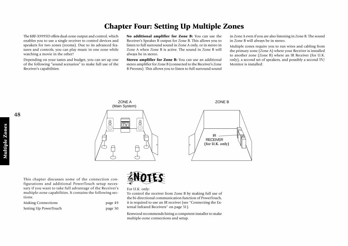
48
Mu
ltip
le Z
on
es
Chapter Four: Setting Up Multiple Zones
Chapter Four: Setting Up Multiple ZonesThe KRF-X9995D offers dual-zone output and control, whichenables you to use a single receiver to control devices andspeakers for two zones (rooms). Due to its advanced fea-tures and controls, you can play music in one zone whilewatching a movie in the other!
Depending on your tastes and budget, you can set up oneof the following “sound scenarios” to make full use of theReceiver’s capabilities:
No additional amplifier for Zone B: You can use theReceiver’s Speaker B output for Zone B. This allows you tolisten to full surround sound in Zone A only, or in stereo inZone A when Zone B is active. The sound in Zone B willalways be in stereo.
Stereo amplifier for Zone B: You can use an additionalstereo amplifier for Zone B (connected to the Receiver’s ZoneB Preouts). This allows you to listen to full surround sound
in Zone A even if you are also listening in Zone B. The soundin Zone B will always be in stereo.
Multiple zones require you to run wires and cabling fromthe primary zone (Zone A) where your Receiver is installedto another zone (Zone B) where an IR Receiver (for U.K.only), a second set of speakers, and possibly a second TV/Monitor is installed:
ZONE A(Main System)
ZONE B
TV
IRRECEIVER
This chapter discusses some of the connection con-figurations and additional PowerTouch setup neces-sary if you want to take full advantage of the Receiver’smultiple-zone capabilities. It contains the following sec-tions:
Making Connections page 49
Setting Up PowerTouch page 50
For U.K. only:To control the receiver from Zone B by making full use ofthe bi-directional communication function of PowerTouch,it is required to use an IR receiver (see "Connecting the Ex-ternal Infrared Receivers" on page 51).
Kenwood recommends hiring a competent installer to makemultiple-zone connections and setup.
(for U.K. only)

49
Mu
ltiple Z
on
es
Chapter Four: Setting Up Multiple Zones
DIGITAL OUT
Y
COMPONENT VIDEOZONE B PRE OUT
RR L SUB WOOFER CENTERVIDEO
RECEIVER
2-CHANNELPOWERAMPLIFIER
ZONE A ZONE B
Power Amp
LEFTSPEAKER
RIGHTSPEAKER
Making ConnectionsThis section describes how to connect speakers in the twozones to support the different scenarios. Before you readthis section, Kenwood recommends reading “Connecting
Your Speakers” on page 4 of this manual. In addition, thissection discusses how to connect a second TV/Monitor andhow to connect an IR Receiver, IR Repeaters, Relays, and a
TV On/Off Sensor (for use with Perfect Macro).
Scenario 1: Surround Sound in Zone A only/Stereo in Zone A and Stereo in Zone B (Using the Receiver’s Speaker B Outputs)
The five amplifiers built into the receiver meet your soundneeds for both zones. The built-in amplifiers allow you tolisten to full surround sound if you are listening in Zone Aonly, or stereo in Zone A if both zones are active. You willalways hear stereo in Zone B. Make the speaker connectionsas shown in the illustration under “To Connect Front andSurround Sound Speakers:” on page 5, being sure to alsoconnect the Zone B speakers to the SPEAKER B bindingpost.
You use an additional stereo amplifier for Zone B. This al-lows you to listen to full surround sound in Zone A even ifboth zones are active. You will always hear stereo in ZoneB. Make the speaker and amplifier connections as shown inthe illustration.
Scenario 2: Surround Sound in Zone A and Stereo in Zone B (Using a Stereo Amplifier in Zone B)
Both Scenarios: Connecting a Second TV/MonitorIf you plan to watch movies, or any other visual entertain-ment activity in Zone B, you must connect an additionalTV/Monitor. To do so, connect a standard composite videocable from the Zone B TV to the ZONE B PRE OUT VIDEOjack.
The above is possible only when the composite signals areinput.
FRONT SPEAKERS(6–16Ω) R
L
A B
ZONE A ZONE B
LEFTSPEAKER
RIGHTSPEAKER
RECEIVER
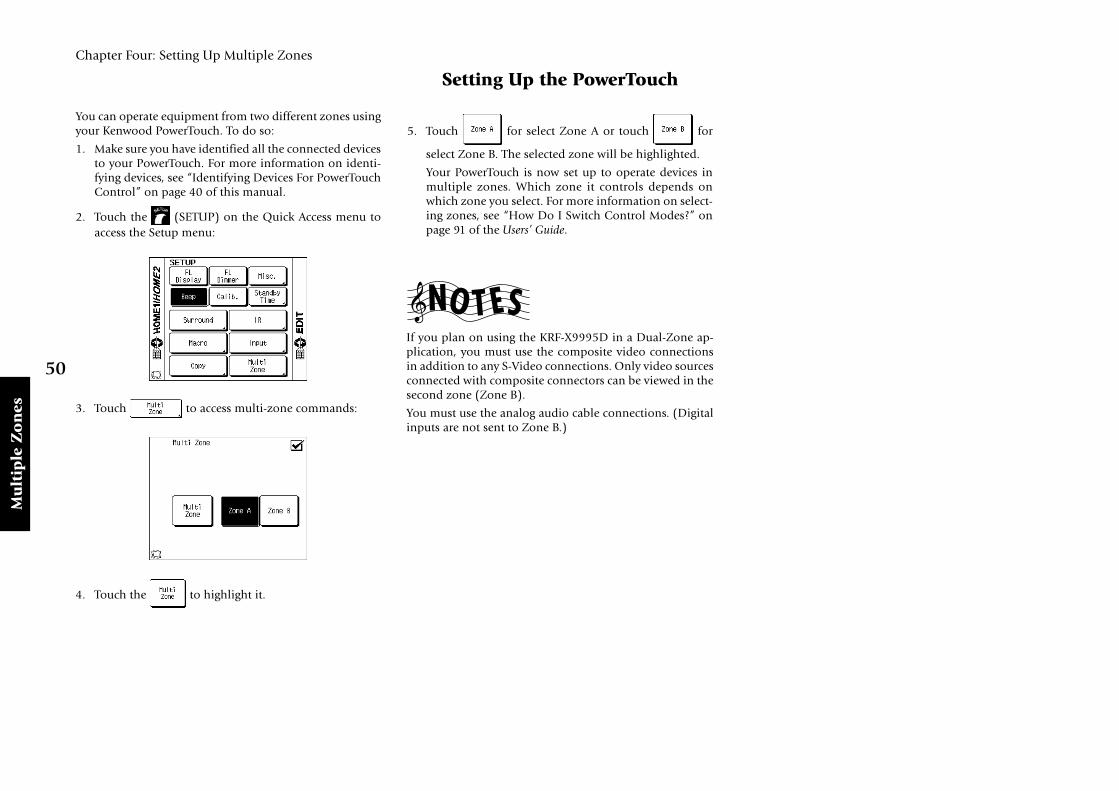
50
Mu
ltip
le Z
on
es
Chapter Four: Setting Up Multiple Zones
Setting Up the PowerTouch
You can operate equipment from two different zones usingyour Kenwood PowerTouch. To do so:
1. Make sure you have identified all the connected devicesto your PowerTouch. For more information on identi-fying devices, see “Identifying Devices For PowerTouchControl” on page 40 of this manual.
2. Touch the (SETUP) on the Quick Access menu toaccess the Setup menu:
3. Touch to access multi-zone commands:
4. Touch the to highlight it.
5. Touch for select Zone A or touch for
select Zone B. The selected zone will be highlighted.
Your PowerTouch is now set up to operate devices inmultiple zones. Which zone it controls depends onwhich zone you select. For more information on select-ing zones, see “How Do I Switch Control Modes?” onpage 91 of the Users’ Guide.
If you plan on using the KRF-X9995D in a Dual-Zone ap-plication, you must use the composite video connectionsin addition to any S-Video connections. Only video sourcesconnected with composite connectors can be viewed in thesecond zone (Zone B).
You must use the analog audio cable connections. (Digitalinputs are not sent to Zone B.)

51
Mu
ltiple Z
on
es
Chapter Four: Setting Up Multiple Zones
Connecting the External Infrared Receivers (for U.K. only)
OPTICAL
VIDEO4
VIDEO3
VIDEO2
CD-R
MD/TAPE1
CD1
DVD
EXT.CONTROLRS-232C
DIGITAL INCOAXIAL
DIGITAL OUT
VIDEO3 IN
COMPONENT VIDEO
DVDIN
MONITOROUT
MONITOROUT
PLAYIN
PLAYIN
PLAYIN
PLAYIN
RECOUT
RECOUT
PLAYIN
S VIDEO VIDEOPRE OUTZONE B PRE OUT
R LAUDIO
R LFRONTR LSURROUNDR LR L SURROUND BACKSUB WOOFER CENTERVIDEO
R LB A
AUDIO
VIDEO1
VIDEO2
VIDEO3
VIDEO4
DVD FRONT
DVD/6CH
INPUT
SURROUND
CENTER SUBWOOFER
PHONO
CD1
RECOUT
PLAYIN
MD/TAPE1
RECOUT
PLAYIN
CD-R
RECOUT
PLAYIN
CD2/TAPE2
MONITOR
CENTERSPEAKER
(6–16Ω)
SURROUNDSPEAKERS
(6–16Ω)
AC 120V 60HzSWITCHED TOTAL90W 0.75A MAX.
FRONT SPEAKERS(6–16Ω)
ANTENNA
GNDAM
FM 75Ω
SYSTEMCONTROL
SL16 TEXT
REMOTE
TV ON/OFFSENSOR
RELAYCONTROL
IR OUTLCD
REMOTE
IR RECEIVERIN
IR RECEIVERIN
DVD CONTROL
C
R
L
R
L
A B
DC5V 10mADC12V 20mADC12V 20mA DC12V 20mA
AC 220 – 240V
AC 110 –120V
50 µsAM 9kHz FM 50kHz
75 µsAM 10kHzFM 100kHz
DE-EMPHASISCHANNEL SPACE
PR/CR
PB/CB
Y
PR/CR
PB/CB
Y
PR/CR
PB/CB
Y
IR OUT LCD
MONITOR
IR RECEIVERIR RECEIVER
MONITOR
IR receiver's input cable
IR receiver's input cableIR receiver's output cable
IR receiver's output cable
In case of use in ZONE B
Your new audio-video receiver supports two-way externalinfrared (IR) remote transceiver control. The two-way exter-nal infrared (IR) remote transceiver enables you to use theReceiver’s PowerTouch to operate the receiver if it is:
• in a stereo closet/cabinet
• behind glass doors
• in another zone
• in any situation where the device to be controlled is notvisible
For more information about using external IR receivers inanother zone, see “Chapter Four: Setting Up Multiple Zones”on page 48.
To Connect IR Receivers (IR Transceivers):1. Connect the IR receiver’s output cable to the Receiver’s
IR RECEIVER IN jack. This jack supports a 12V 20mAsignal.
2. Connect the IR receiver’s input cable to the Receiver’s IRRECEIVER OUT jack.
3. (For some IR receiver)
Connect an AC adaptor to the IR receiver. Do not plugthe adaptor into the wall until all connections aremade.
Make sure that the input/output terminals and electricalspecifications of the IR receiver match those of this unit.(see Chapter Five: Specifications)
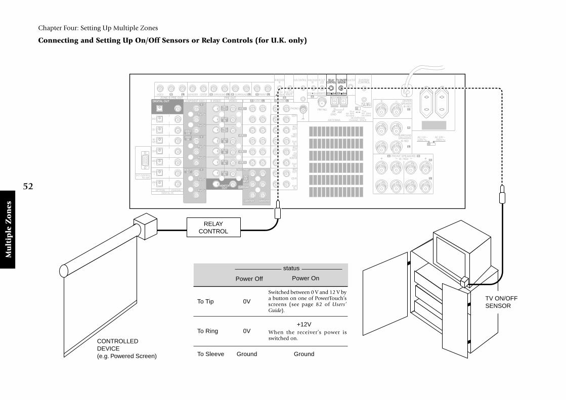
52
Mu
ltip
le Z
on
es
Chapter Four: Setting Up Multiple Zones
Connecting and Setting Up On/Off Sensors or Relay Controls (for U.K. only)
OPTICAL
VIDEO4
VIDEO3
VIDEO2
CD-R
MD/TAPE1
CD1
DVD
EXT.CONTROLRS-232C
DIGITAL INCOAXIAL
DIGITAL OUT
VIDEO3 IN
COMPONENT VIDEO
DVDIN
MONITOROUT
MONITOROUT
PLAYIN
PLAYIN
PLAYIN
PLAYIN
RECOUT
RECOUT
PLAYIN
S VIDEO VIDEOPRE OUTZONE B PRE OUT
R LAUDIO
R LFRONTR LSURROUNDR LR L SURROUND BACKSUB WOOFER CENTERVIDEO
R LB A
AUDIO
VIDEO1
VIDEO2
VIDEO3
VIDEO4
DVD FRONT
DVD/6CH
INPUT
SURROUND
CENTER SUBWOOFER
PHONO
CD1
RECOUT
PLAYIN
MD/TAPE1
RECOUT
PLAYIN
CD-R
RECOUT
PLAYIN
CD2/TAPE2
MONITOR
CENTERSPEAKER
(6–16Ω)
SURROUNDSPEAKERS
(6–16Ω)
AC 120V 60HzSWITCHED TOTAL90W 0.75A MAX.
FRONT SPEAKERS(6–16Ω)
ANTENNA
GNDAM
FM 75Ω
SYSTEMCONTROL
SL16 TEXT
REMOTE
TV ON/OFFSENSOR
RELAYCONTROL
IR OUTLCD
IR OUT LCDREMOTE
IR RECEIVERIN
IR RECEIVERIN
DVD CONTROL
C
R
L
R
L
A B
DC5V 10mADC12V 20mADC12V 20mA DC12V 20mA
AC 220 – 240V
AC 110 –120V
50 µsAM 9kHz FM 50kHz
75 µsAM 10kHzFM 100kHz
DE-EMPHASISCHANNEL SPACE
PR/CR
PB/CB
Y
PR/CR
PB/CB
Y
PR/CR
PB/CB
Y
RELAYCONTROL
CONTROLLEDDEVICE(e.g. Powered Screen)
TV ON/OFFSENSOR
Switched between 0 V and 12 V bya button on one of PowerTouch’sscreens (see page 82 of Users’Guide).
When the receiver’s power isswitched on.
To Tip 0V
To Ring 0V+12V
To Sleeve Ground Ground
status
Power Off Power On

53
Mu
ltiple Z
on
es
Chapter Four: Setting Up Multiple Zones
Connecting and Setting Up On/Off Sensors or Relay Controls (for U.K. only), continued
The KRF-X9995D (model for U.K.) supports 2 types of ad-ditional external controls:
• A relay control that enables you to operate external re-lay-control devices (such as the Xantech 590-0 program-mable controller, via Xantech’s 599-00 pulse switchingmodule).
• A TV ON/OFF sensor that enables you to use the PerfectMacro feature (described further in the Users’ Guide) toaccurately sense whether the TV is already on or off andadjust accordingly.
To Connect Relay Controls:1. Consult the relay control’s manual for compatibility in-
formation and installation instructions before connect-ing it to your new receiver. If you install the control in-correctly or connect an incompatible control to the re-ceiver, you may damage the control and your new re-ceiver.
2. Connect the control cable to the receiver’s RELAY CON-TROL jack. This jack supports a 12V, 20mA signal.
Do not connect multiple 599-00 switching modules to eachother or to the receiver, as this can exceed the maximumcurrent capacity of the jack and damage your receiver.
To Connect TV ON/OFF Sensors:1. Connect the sensor to the TV as described in the sensor’s
manual.
2. Connect the sensor cable to the receiver’s TV ON/ OFFSENSOR jack. This jack supports a 5V, 10mA signal.
JDS:PSS-TV or NILES:LS-1, APC-2 sensors are compatiblewith your new receiver.

54
Spec
ific
atio
ns
Chapter Five : Specifications
Chapter Five: SpecificationsRead this page carefully to ensure safe operation.
NOTE: Do not use contact cleaning agents because theycould cause a malfunction. Be especially careful not to usecontact cleaning agents containing oil, since they may de-form the plastic components.
KRF-X9995D (for U.K.)Audio Section
Rated Output Power during stereo operation1 kHz, 0.03% T.H.D. , 6Ω (DIN/IEC) ........... 140W + 140 W20 Hz ~ 20 kHz, 0.03% T.H.D. , 6Ω (IEC).......................................................................... 130W + 130 W
Effective Output Power during surround operation1 kHz, 0.06% T.H.D. at 6 Ω, all channel driven(Front, Center, Surround) .................................. 130 W × 5
Total Harmonic Distortion ............. 0.005 % (1 kHz, 65 W, 6 Ω)
Frequency Response (IHF’66)Line (CD1, MD/TAPE, CD2/TAPE2 MONITOR, CD-R,VIDEO 1 - 4, DVD/6CH.) ......... 7 Hz ~ 100 kHz, 0 dB, -3 dB
Signal to Noise Ratio (IHF ‘66)PHONO (MM) ............................................................... 76 dBCD1 .................................................................................. 98 dB
Input Sensitivity / ImpedancePHONO (MM) ................................................ 4.0 mV / 47 kΩCD1 ................................................................. 300 mV / 47 kΩDVD/6CH. ....................................................... 300 mV / 47 kΩ
Output Level / ImpedanceTAPE REC ..................................................... 300 mV / 2.2 k ΩPRE OUT (Front, Center, Surround, Surround back)................................................................................ 1 V / 470 Ω
PRE OUT (Subwoofer) ................................... 1.8 V / 470 ΩTone Control
Bass ............................................................ + 7 dB (at 100 Hz)Treble ......................................................... + 7 dB (at 10 kHz)
Loudness Control Volume at -30 dB level............................................. +6 dB (100 Hz), +3 dB (10 kHz)
Digital Audio Section
Sampling Frequency ............. 32 kHz, 44.1 kHz, 48 kHz, 96 kHzInput Level / Impedance / Wavelength
Optical ........................ -15 dBm ~ -21 dBm, 660 nm +30 nmCoaxial ............................................................ 0.5 Vp-p / 75 Ω
Output Level / Impedance / WavelengthOptical ........................ -15 dBm ~ -21 dBm, 660 nm ±30 nmCoaxial ............................................................ 0.5 Vp-p / 75 Ω
Video Section
Video Inputs / OutputsVideo (composite) ............................................. 1 Vp-p / 75 ΩS Video ( luminance signal) .............................. 1 Vp-p / 75 Ω (chrominance signal) .................. 0.286 Vp-p / 75 ΩComponent (luminance signal) ....................... 1 Vp-p / 75 Ω (PB/PR-signal) ............................. ±0.350 Vp-p / 75 Ω
FM Tuner Section
Tuning Frequency Range ........................... 87.5 MHz ~ 108 MHz
Usable Sensitivity (DIN at 75 Ω)Mono .................. 1.3 µV/ 13.2 dBf (40 kHz dev., S/N 26 dB)
Stereo ................ 35.1 µV/ 42.1 dBf (46 kHz dev., S/N 46 dB)
Total Harmonic Distortion (DIN at 1 kHz)Mono ................................................... 0.2 % (71.2 dBf input)Stereo ................................................... 0.8 % (71.2 dBf input)
Signal to Noise Ratio (DIN weighted, 1kHz)Mono ............................. 65 dB (40 kHz dev., 71.2 dBf input)Stereo ............................. 60 dB (40 kHz dev., 71.2 dBf input)
Stereo Separation (DIN at 1 kHz) ..................................... 36 dB
Selectivity (DIN ±300 kHz) ............................................... 64 dB
Frequency Response ................ 30 Hz ~ 15 kHz, +0.5 dB, -3.0 dB
AM Tuner Section
Tuning Frequency Range ........................... 531 kHz ~ 1,602 kHz
Usable Sensitivity (30 % mod., S/N 20 dB)........................................................................... 16 µV / (500 µV/m)
Signal to Noise Ratio (30 % mod., 1 mV input) .............. 50 dB
Relay and IR In/Out Section
Relay Control TerminalMaximum Output Current ............................................ 20 mAOperating Voltage .............................................................. 12 VOutput Impedance .......................................................... 470 Ω
IR Receiver In TerminalMaximum Output Current ............................................ 20 mAOperating Voltage .............................................................. 12 VOutput Impedance .......................................................... 470 Ω
IR Out LCD Remote TerminalMaximum Output Current ............................................ 20 mAOperating Voltage ................................................................ 5 VOutput Impedance .......................................................... 470 Ω
SHAPE OF PLUG TO BE CONNECTED:
IR IN/OUT SPECIFICATION:
RELAY CONTROL SPECIFICATION:
IR Receiver In
To Tip Signal Signal
To Ring Ground
To Sleeve +12V Ground
IR Out LCDRemote
To Tip 0V 0V +12V
To Ring 0V +12V
To Sleeve Ground Ground Ground
When a specificbutton on one ofPowerTouch’sscreen is pressed.
PowerOff
PowerOn
status
Terminal
IR Receiver In and IR OutLCD Remote
DVD Control
Stereo mini plug Mono mini plug
Sleeve Sleeve
Ring
Tip Tip

55
Specificatio
ns
Chapter Five : Specifications
KRF-X9995D (for Other Countries)Audio Section
Rated Output Power during stereo operation20 Hz ~ 20 kHz, 0.7% T.H.D. , 6Ω (IEC).......................................................................... 150W + 150 W
130 watts per channel minimum RMS, both channelsdriven, at 6 Ω from 20Hz to 20kHz with no more than0.05% total harmonic distortion (FTC).
Effective Output Power during stereo operation1 kHz, 10% T.H.D. at 6 Ω ..............................180 W + 180 W
Effective Output Power during surround operationFront1 kHz, 10% T.H.D. at 6 Ω, one channel driven..................................................................... 200 W + 200 WCenter1 kHz, 10% T.H.D. at 6 Ω, one channel driven..................................................................... 200 W + 200 WSurround1 kHz, 10% T.H.D. at 6 Ω, one channel driven..................................................................... 200 W + 200 W
Total Harmonic Distortion ............. 0.005 % (1 kHz, 75 W, 6 Ω)
Frequency Response (IHF’66)Line (CD1, MD/TAPE, CD2/TAPE2 MONITOR, CD-R,VIDEO 1 - 4, DVD/6CH.) ......... 7 Hz ~ 100 kHz, 0 dB, -3 dB
Signal to Noise Ratio (IHF ‘66)PHONO (MM) ............................................................... 76 dBCD1 .................................................................................. 98 dB
Input Sensitivity / ImpedancePHONO (MM) ................................................ 4.0 mV / 47 kΩCD1 ................................................................. 300 mV / 47 kΩDVD/6CH. ....................................................... 300 mV / 47 kΩ
Output Level / ImpedanceTAPE REC .......................................................300 mV / 2.2 kΩPRE OUT (Front, Center, Surround, Surround back)................................................................................ 1 V / 470 Ω
PRE OUT (Subwoofer) ....................................... 1.8 V / 470 Ω
General
Power consumption .......................................................... 600 W
AC outletSwitched ................................................... 2 (total 90 W max.)
Dimensions .................................................................. W : 440mmH : 191mmD : 416mm
Weight (Net) ..................................................................... 20.2 kg
Tone ControlBass ............................................................ + 7 dB (at 100 Hz)Treble ......................................................... + 7 dB (at 10 kHz)
Loudness ControlVolume at -30 dB level ....... +6 dB (100 Hz), +3 dB (10 kHz)
Digital Audio Section
Sampling Frequency ............. 32 kHz, 44.1 kHz, 48 kHz, 96 kHzInput Level / Impedance / Wavelength
Optical ........................ -15 dBm ~ -21 dBm, 660 nm +30 nmCoaxial ............................................................ 0.5 Vp-p / 75 Ω
Output Level / Impedance / WavelengthOptical ........................ -15 dBm ~ -21 dBm, 660 nm +30 nmCoaxial ............................................................ 0.5 Vp-p / 75 Ω
Video Section
Video Inputs / OutputsVideo (composite) ............................................. 1 Vp-p / 75 ΩS Video ( luminance signal) .............................. 1 Vp-p / 75 Ω (chrominance signal) .................. 0.286 Vp-p / 75 ΩComponent (luminance signal) ....................... 1 Vp-p / 75 Ω (Cb/Cr-signal) ............................ ±0.350 Vp-p / 75 Ω
FM Tuner Section
Tuning Frequency Range ........................... 87.5 MHz ~ 108 MHz
Usable Sensitivity (Mono).................... 1.3 µV (75 Ω) / 13.2 dBf (75 kHz dev., sinad 30 dB)
50dB Quieting SensitivityStereo .............................................. 25.1 µV (75 Ω) / 39.2 dBf
Total Harmonic Distortion (1 kHz)Mono ................................................... 0.3 % (71.2 dBf input)Stereo ................................................... 0.5 % (71.2 dBf input)
Signal to Noise Ratio (1 kHz, 75 kHz DEV.)Mono ................................................... 75 dB (71.2 dBf input)Stereo ....................................................70 dB (71.2 dBf input)
Stereo Separation (1 kHz) ................................................. 40 dB
Selectivity (+400 kHz) ....................................................... 50 dB
Frequency Response ................ 30 Hz ~ 15 kHz, +0.5 dB, -3.0 dB
AM Tuner Section
Tuning Frequency Range9kHz step (except for Australia) .......... 531 kHz ~ 1,602 kHz10kHz step ............................................. 530 kHz ~ 1,610 kHz
Usable Sensitivity (30 % mod., S/N 20 dB)........................................................................... 16 µV / (500 µV/m)
Signal to Noise Ratio (30 % mod. 1 mV input) ............... 50 dBGeneral
Power consumption .......................................................... 600 W
AC outletSwitched (except for Australia) .............. 2 (total 90 W max.)Switched (for Australia) .......................... 1 (total 90 W max.)
Dimensions .................................................................. W : 480mmH : 191mmD : 416mm
Weight (Net) ..................................................................... 22.2 kg
Kenwood follows a policy of continuous advancements indevelopment. For this reason, specifications may be changedwithout notice.
Full performance may not be exhibited in extremely coldlocations (below 0 deg. C).

56
Ind
ex
Numerics200-Disc CD Changer
connecting ................................................ 17connecting SL16 text cable ...................... 17identifying to PowerTouch ...................... 40SL16/XS8 switch ....................................... 17
AAM antenna
connecting ................................................ 33preventing hum interference ................... 33
amplifierconnecting .............................................. 6, 8using in multiple zones ........................... 49
analog cablesDVD player ............................................... 19laser disc player .................................. 26, 28using in multiple zone ............................ 50
antennas, connecting ........................................ 33audio cables
200-Disc CD Changer .............................. 17cable TV .................................................... 12camcorder .................................................. 31CD-R recorder .......................................... 20DVD player ............................................... 18laser disc player (AC-3 Output) .............. 26laser disc player (no AC-3 Output) ......... 28MD recorder ............................................. 22primary CD player ................................... 16primary tape deck .................................... 22satellite tuner ............................................ 12secondary CD player ................................ 24second tape deck ...................................... 24TV ............................................................... 10VCR ..................................................... 14, 31
Bbatteries, installing in PowerTouch ................. 34bass peak level .................................................. 39
Ccable radio, connecting (call provider) ........... 33cable TV
connecting ................................................ 12identifying to PowerTouch ...................... 40with RCA video output ............................ 13without RCA video output ...................... 13
camcorder, connecting ...................................... 31CD player
connecting ................................................ 16identifying to PowerTouch ...................... 40
CD-R Recorderconnecting ................................................ 20identifying to PowerTouch ...................... 40
CD2/TAPE2, setting the input icon ................. 40center speaker, connecting ............................. 4, 8clearing PowerTouch stored settings ............... 35coaxial cable
200-Disc CD Changer .............................. 17cable TV .................................................... 12CD player .................................................. 16CD-R recorder .......................................... 20DVD player ............................................... 18LD player ............................................ 26, 28MD recorder ............................................. 22satellite tuner ............................................ 12
communication cable, connecting .................. 16component video cable
cable TV .................................................... 12DVD player ............................................... 18satellite tuner ............................................ 12TV ............................................................... 10
connecting200-Disc CD Changer .............................. 17AM antenna .............................................. 33amplifier ........................................... 6, 8, 49antennas ................................................... 33audio cable to MD recorder ................... 22audio cables to VCR ................................ 14cable radio (call provider) ....................... 33camcorder .................................................. 31CD player .................................................. 16CD-R Recorder ......................................... 20DVD player ............................................... 18external infrared receiver .......................... 51FM antenna .............................................. 33laser disc player with AC-3 Output ......... 26MD recorder ............................................. 22On/Off sensors ......................................... 52primary tape deck .................................... 22relay controls ............................................ 52second VCR .............................................. 15speakers .................................................. 4, 6speakers multiple zones .......................... 49system control cable to primary
tape deck .............................................. 22tape deck ................................................... 22
turntable/record player ............................ 30turntable’s ground cable to receiver ........ 30TV ........................................................ 10, 49TV On/Off sensors ................................... 52VCR ..................................................... 14, 31video cables to VCR ................................. 14video-CD compatible CD player ............. 17
connection warninganalog cables, laser disc player .......... 27, 29DVD player ............................................... 19laser disc player .................................. 27, 29receiver vs. relay controls ......................... 53second CD player ..................................... 25second tape deck ...................................... 25
customize .......................................................... 43
Ddeleting, PowerTouch setup codes ................... 40devices
identifying to PowerTouch ...................... 40digital cable
200-Disc CD Changer .............................. 17cable TV .................................................... 12CD player .................................................. 16CD-R recorder .......................................... 20DVD player ............................................... 18LD player ............................................ 26, 28MD recorder ............................................. 22satellite tuner ............................................ 12
Dolby Digital (AC-3) RF Out ........................... 27DVD player
connecting ................................................ 18identifying to PowerTouch ...................... 40
Eexternal infrared receiver, connecting ............... 51
FFM antenna, connecting ................................... 33front speakers, connecting ................................. 4
Gground cable, connecting turntable ................. 30
Hhum interference .............................................. 33
IIR receiver
connecting ................................................. 51
Llaser disc player
identifying to PowerTouch ...................... 40RF Demodulator ...................................... 26with AC-3 Output, connecting ................ 26with PCM Digital Output, connecting .... 28without AC-3 Output, connecting .......... 28without Dolby Digital Output,
connecting ............................................ 28left speakers
front, connecting ........................................ 4surround, connecting ............................. 4, 6
MMD recorder
connecting ................................................ 22identifing to PowerTouch ........................ 40
multiple zonesconnecting relays ...................................... 52connecting second TV monitor ............... 49connecting TV On/Off sensor ................. 52IR receiver, connecting .............................. 51set up ........................................................ 50sound scenarios ....................................... 49sound setup .............................................. 50using external infrared receiver ................ 51
Nnavigating PowerTouch interface ..................... 36
OOn/Off sensors, connecting ............................. 52optical cable
200-Disc CD Changer .............................. 17cable TV .................................................... 12CD player .................................................. 16CD-R recorder .......................................... 20DVD player ............................................... 18LD player ............................................ 26, 28MD recorder ............................................. 22satellite tuner ............................................ 12
Ppowered subwoofer, connecting ........................ 6

57
Ind
ex
PowerTouchclearing stored settings and
reconfiguring ........................................ 35deleting setup code .................................. 40identifying devices ................................... 40identifying receiver model type ............... 35installing batteries .................................... 34introductory information ........................ 34navigating the display screen .................. 36operating components through
external infrared receiver ...................... 51replacing old setup code with new ......... 40selecting main menu ............................... 36selecting model type ................................ 35selecting speakers ..................................... 37setup for multiple zone use ..................... 50setup menu ............................................... 36speaker distance, setting .......................... 38speaker level, setting ................................ 39speaker type, setting ................................. 37storing radio stations ................................ 41
Rradio stations, storing in memory ............. 41, 47RDS stations, storing in PowerTouch ........ 41, 47receiver
identifying model type to PowerTouch .. 35record player/turntable, connecting ................ 30relay controls
connecting ................................................ 52connection warning ................................. 53
resettingPowerTouch .............................................. 35
right speakersfront, connecting ........................................ 4surround, connecting ............................. 4, 6
RS-232C connector ............................................. 2
SS video cable
cable TV .................................................... 12DVD player ............................................... 18laser disc player .................................. 26, 28satellite tuner ............................................ 12TV ............................................................... 10VCR ........................................................... 14
satellite tunerconnecting ................................................ 12
identifying to PowerTouch ...................... 40second tape deck
connecting ................................................ 25connecting audio cable ............................ 25connection warning ................................. 25identifying to PowerTouch ...................... 40
second VCRconnecting ................................................ 15identifying to PowerTouch ...................... 40
setup codesdeleting ..................................................... 40
setup menu, on PowerTouch ........................... 36SL16
CD player .................................................. 17chained connections ................................ 32system control mode ............................... 32tapedack .................................................... 23XS8 switch, CD player ............................. 17
sound pressure level meter ............................... 39sound scenarios
Zone A ................................................ 48, 49Zone B ................................................ 48, 49
speakersconnecting ........................................ 4, 6, 49connecting in multiple zones .................. 49setting with PowerTouch ......................... 37
specifications .................................................... 54storing radio stations in memory .............. 41, 47subwoofer
connecting .................................................. 6supplemental power amplifiers, connecting ..... 8surround sound
connecting speakers ............................... 4, 6system control cables
200-Disc CD Changer .............................. 17CD player .................................................. 16connection warning ................................. 32MD recorder ............................................. 22tape deck ................................................... 22
system control chaining ................................... 32
Ttape deck
connecting ................................................ 22identifying to PowerTouch ...................... 40
THX speaker ...................................................... 38turntable/record player, connecting ................ 30
TVconnecting ................................................. 10
identifying to PowerTouch ...................... 40On/Off sensors, connecting .................... 52watching without using receiver .............. 11
VVCR
connecting ................................................ 14identifying to PowerTouch ...................... 40
video cablescable TV .................................................... 12camcorder .................................................. 31DVD player ............................................... 18laser disc player (AC-3 Output) .............. 26laser disc player (no AC-3 Output) ......... 28satellite tuner ............................................ 12TV .............................................................. 12VCR ........................................................... 14
video CD-compatible CD player, connecting ... 17
Zzone A
sound scenario .............................................. 49zone B
connecting second TV .................................. 49sound scenario .............................................. 49

For your recordsRecord the serial number, found on the back of the unit, in the spaces designatedon the warranty card, and the space provided below. Refer to the model andserial numbers whenever you call upon your dealer for information or service onthis product.Model Serial Number