kulicki, j.m. highway truss bridges. bridge engineering ...freeit.free.fr/bridge engineering...
TRANSCRIPT

Kulicki, J.M. "Highway Truss Bridges." Bridge Engineering Handbook. Ed. Wai-Fah Chen and Lian Duan Boca Raton: CRC Press, 2000

16Highway Truss Bridges
16.1 Truss ConfigurationsHistorical • Modern
16.2 Typical Components, Nomenclature, and Materials
16.3 Methods of AnalysisTwo-Force Member Methods — Pin-Connected Truss • Computer Methods
16.4 Floor Systems and Framing DetailsConventional Deck Systems Not Integral with Truss Chords • Decks Integral with Truss Chords
16.5 Special DetailsHangers and Dummy Chords for Cantilever Bridges • Bearings • Wind Tongue and Bearings for Transverse Forces
16.6 Camber and ErectionCamber for Vertical Geometry • Camber of Joints • Common Erection Methods
16.7 Summary
16.1 Truss Configurations
16.1.1 Historical
During the 1800s, truss geometries proliferated. The Historic American Engineering Record illustrates32 separate bridge truss geometries in its 1976 print shown in Figure 16.1 [1]. These range fromthe very short King Post and Queen Post Trusses and Waddell “A” trusses to very complex indeter-minate systems, including the Town Lattice and Burr Arch truss. Over a period of years followingSquire Whipple’s breakthrough treatise on the analysis of trusses as pin-connected assemblies, i.e.,two force members, a number of the more complex and less functional truss types graduallydisappeared and the well-known Pratt, Howe, Baltimore, Pennsylvania, K truss and Warren con-figurations came into dominance. By the mid-20th century, the Warren truss with verticals was adominant form of truss configuration for highway bridges, and the Warren and K trusses weredominant in railroad bridges. The Historic American Engineering Record indicates that the Warrentruss without verticals may have appeared as early as the mid-1880s, but was soon supplanted bythe Warren truss with verticals, as this provided a very convenient way to brace compression chords,reduce stringer lengths, and frame sway frames into the relatively simple geometry of the verticalmembers.
John M. KulickiModjeski and Masters, Inc.
© 2000 by CRC Press LLC

16.1.2 Modern
Few single span trusses are used as highway bridges today, although they are still used for railroadbridges. Modern highway trusses are usually either continuous or cantilever bridges and are typicallyWarren trusses with or without verticals. Some typical configurations are shown in Figure 16.2.
Throughout the 1980s and 1990s, the Warren truss without verticals has resurfaced as a moreaesthetically pleasing truss configuration, especially in the parallel chord configuration, and this hasled to a significant simplification in truss detailing, because sway frames are typically omitted inthis form of truss, except for portals. The Warren truss without verticals received a great deal of useon the Japanese Railroad System and, more recently, in U.S. highway practice as exemplified in theCooper River Bridge near Charleston, South Carolina, and the Kanawha River Bridge near Charles-ton, West Virginia; such a bridge configuration is shown in Figure 16.3 as it was considered oneoption for the Second Blue Water Bridge (281 m main span) between Port Huron, Michigan, andPoint Edward, Ontario, Canada.
The truss bridge behaves much like a closed box structure when it has four planes capable ofresisting shear and end portals sufficient to transmit shear back into vertical loads at the bearings.Given the need for a box configuration to resist vertical and lateral loads, it is possible that theconfiguration could be either rectangular, i.e., four-sided, or triangular, if that geometry is able to
FIGURE 16.1 Historic trusses.
© 2000 by CRC Press LLC

accommodate the roadway clearances. Issues of redundancy should be addressed, either by supple-mentary load paths, e.g., prestressing, or by sufficiently improved material properties, primarilytoughness, to make a triangular configuration acceptable to owners, but it is certainly within thetechnical realm of reason.
16.2 Typical Components, Nomenclature, and Materials
Components and NomenclatureThe truss bridge is usually characterized by a plethora of bracing and wind-carrying members inaddition to those members seen in front elevation. Typical members of a simple single span through-truss are identified in Figure 16.4, taken from Ref. [2].
FIGURE 16.2 Typical modern highway truss configuration.
FIGURE 16.3 Second Blue Water Bridge — parallel chord truss study option.
© 2000 by CRC Press LLC

The lateral members in the planes of the top and bottom chords resist wind loads and brace thecompression chords. Sway frames are thought to square the truss and increase its torsional rigidity.End portals carry torsional loads resulting from uneven vertical loads and wind loads into thebearings.
It is the visual impact of the various members, especially bracing members, which contribute toaesthetic opposition to many truss designs. However, if unforeseen events cause damage to a maintruss member, these bracing members can serve as additional load paths to carry member loadaround a damaged area.
Truss MembersSome of the cross sections used as modern truss members are shown in Figure 16.5. Truss membershave evolved from rods, bars, and eyebars to box and H-shaped members. Generally speaking, thebox members are more structurally efficient and resist the tendency for wind-induced vibrationbetter than H-shapes, whereas H-shapes are perceived as being more economical in terms offabrication for a given tonnage of steel, generally easier to connect to the gusset plates because ofopen access to bolts, and easier to maintain because all surfaces are accessible for painting. The useof weathering steel offsets these advantages.
Even in the late 1990s, box members are widely used and, in some cases, the apparent efficiencyof the H-shape is offset by the need to make the members aerodynamically stable. The choice isclearly project specific, although the H-shaped sections have a relatively clear advantage in the caseof tension members because they are easier to connect to gusset plates and easier to paint as indicatedabove, without the stability design requirements needed for compression members. They are,however, more susceptible to wind-induced vibrations than box shapes. Box shapes have an advan-tage in the case of compression members because they usually have lower slenderness ratios aboutthe weak axis than a corresponding H-shaped member.
The sealing of box shapes to prevent corrosion on the inside of the members has been approachedfrom many directions. In some cases, box shapes may be fully welded, except at access locations at
FIGURE 16.4 Typical truss members.
© 2000 by CRC Press LLC

the ends used to facilitate connection to gusset plates. Sealing of box members has met with mixedsuccess. In some instances, even box members which have been welded on all four sides and havehad welded internal squaring and sealing diaphragms have been observed to collect moisture. Theissue is that the member need not be simply watertight to prevent the infiltration of water in theliquid form, it must also be airtight to prevent the natural tendency for the member to “breath”when subjected to temperature fluctuations, which tends to draw air into the member through eventhe smallest cracks or pinholes in the sealing system. This air invariably contains moisture and canbe a recurring source of condensation, leading to a collection of water within the member. In somecases, box members have been equipped with drainage holes, even though nominally sealed, inorder to allow this condensate to escape. In some instances, box members have been sealed andpressurized with an inert gas, typically nitrogen, in order to establish that adequate seals have beendeveloped, as well as to eliminate oxygen from the inside of the member, thus discouraging corro-sion. Box members have been built with valve stems in order to monitor the internal pressure, aswell as to purge and refill the inert gas corrosion protection. Various types of caulking have beenused to try to seal bolted joints with mixed success.
Due to the increased interest in redundancy of truss bridges, stitch-bolted members have beenused in some cases. Because a bolt does not completely fill a hole, this does leave a path for wateringress, making adequate ventilation and drainage of the member important.
The future of truss member configurations is somewhat dependent on the evolution of newmaterials as discussed below.
MaterialsEarly trusses were made of timber. Over a period of time, the combination of timber compressionmembers and wrought iron tension members was evolved and eventually the timber componentswere replaced by cast iron. After the construction of the Eads Bridge in St. Louis, steel became morewidely used and remains today the predominant, and almost exclusive, material for truss construction.
FIGURE 16.5 Cross sections of modern truss members.
© 2000 by CRC Press LLC

As truss bridges reached longer and longer spans, they became the natural platform for the intro-duction of new steels, including the silicon steels in the earlier part of this century, weathering steels,copper-bearing steels, low-alloy steels, and even the high-yield-strength quenched and temperedalloy steels, such as ASTM A514/A517. An earlier version of weathering-type steels was used intrusses during the first quarter of the 20th century and was little recognized for their weatheringcapabilities until relatively recently.
By the current era (1998), 345 MPa yield steel dominated, with some use of higher strengthmaterials, especially for very long-span bridges. The recent high-performance steel (HPS) initiativeon the part of the Federal Highway Administration, the steel industry, and the U.S. Navy has led tothe development of steels which hold the promise for relatively high strength, e.g., 485 MPa yieldand higher, relatively favorable yield-to-tensile ratios on the order of 0.85, extraordinary tough-ness which could eliminate fracture as a consideration and with it fracture-critical membersdesignation, reduced interpass temperature controls, and reduced preheat. This new material notonly holds the promise for increased efficiency and cost-effectiveness using conventional box andI-shaped members in truss design, but may also lead to the use of tubular members and castjoints. This sounds like a return to the old Phoenix bridge system, but the increased efficiencyof new materials, as well as the advances in the casting industry, may make field welding of tubularshapes to nodes possible and efficient. The use of high-performance concrete (HPC) truss mem-bers may evolve in which concrete serves as a composite stiffener to relatively thin steel plates incompression members.
Advanced composite materials may lead to further truss efficiencies. A pultruded shape as acompression member, butting into a metallic, concrete, or composite node may be a near-termpossibility. Composite tension members may require a bonding agent, e.g., glue, before it becomespossible to make a fatigue-resistant joint. The problems associated with mechanical fastener-typeconnection will probably be solved sooner or later facilitating the use of advanced composites.
16.3 Methods of Analysis
16.3.1 Two-Force Member Methods — Pin-Connected Truss
In the 1840s, a method of analyzing trusses as pin-connected assemblages was developed and is stillin wide use today. This method is based on assuming that the truss joints are frictionless pins. Thisassumption means that as long as loads are applied to the joints and not along the member length,the only bending is caused by self-weight. Thus, the major force in the member is assumed to actalong its length. This is often called a “two-force member.” The two forces are the axial load at eachend of the member.
Throughout the 19th century and even into the early part of the 20th century, it was commonto use physical pins in truss joints in order to facilitate the interconnection of components ofmembers, and also to replicate the mathematical assumptions. As a truss deflects under loads, thejoints rotate through what are typically very small angles. If the pins truly were frictionless, thetruss members would rotate relative to each other and no end moments would be developed onthe members. The physical pins never really were friction-free, so some moments developed at theends in truss members and these were typically regarded as secondary forces. When pin-endedconstruction gave way to riveted joints and then to bolted or welded joints, the truss joints weredetailed so that the working lines of the members intersected either at a common point, so as toreduce eccentricities or to utilize eccentricities to compensate for the bending caused by the deadweight of the members. In either event, it was widely regarded that the pin-connected analysis modelwas applicable. As will be discussed later, as long as a bridge is properly cambered, it often is anaccurate analysis tool.
Two variations of the pin-connected truss model are in common usage; the method of joints andthe method of sections. Each of these are illustrated below.
© 2000 by CRC Press LLC

16.3.1.1 Method of JointsAs the name implies, the method of joints is based on analysis of free-body diagrams of each of thetruss joints. As long as the truss is determinate, there will be enough joints and equations ofequilibrium to find the force in all the members. Consider the simple example shown in Figure 16.6.This six-panel truss supports a load P at Joint L3. By taking the summation of the moments abouteach end of the bridge, it is possible to determine that the left-hand reaction is ⅔ P and the right-hand reaction is ⅓ P.
Isolating Joint L0, it can be seen that there are two unknowns, the force in Member L0-U1 andthe force in Member L0-L1. For this small truss, and as typically illustrated in most textbooks, thetruss is assumed to be in a horizontal position, so that it is convenient to take one reference axisthrough Member L0-L1 and establish an orthagonal axis through L0. These are commonly calledthe horizontal and vertical axes. The forces parallel to each must be in equilibrium. In this case,that means that the vertical component of the force in Member L0-U1 is equal the reaction RL. Byconsidering the forces in the horizontal direction, the force in Member L0-L1 is equal to thehorizontal component of the force in Member L0-U1. Thus, all of the member forces at L0 can bedetermined.
If we proceed to Joint L1, at which there is no applied load, it is clear that vertical equilibriumof the joint requires that the force in L1-U1 be equal to 0, and that the force in L1-L2 be equal toL0-L1.
Proceeding to Joint U1, it can be seen that, although four members frame into that joint, theforce in two of the members are now known, and the force in the other two members can be foundfrom the equation of equilibrium of forces along the two axes.
The analysis continues in this way from joint to joint.
16.3.1.2 Method of SectionsThe method of sections proceeds by identifying free-body diagrams which contain only twounknowns, so that equilibrium of the sum of the moment about one joint and the equilibrium ofthe sum of the shears through a panel are sufficient to determine the two unknown truss forces.Consider Section AA in Figure 16.7 which shows a portion of the same truss shown in Figure 16.6.If we consider the free-body diagram to the left of Section AA, it is clear that the shear in the panelis equal to the reaction RL and that this can be reacted only by the force L0-U1. Similarly, since thesection and hence the free-body diagram is taken just to the left of the Joints L1 and U1, summingmoments about Joint U1 or, more accurately, the end of Member L0-U1 an infinitesimally smalldistance to the left of the section line enables us to compute the force in L0-U1.
If we consider Section BB, it can be seen that the sum of the moments about the lower chordjoint enables us to find the force in the top chord, and the shear in this panel enables us to find theforce in the diagonal directly.
The analysis then proceeds from section to section along the truss. As a practical matter, acombination of the method of section and the method of joints usually results in the most expe-ditious calculations.
16.3.1.3 Influence Lines for a TrussAn influence line is a graphical presentation of the force in a truss member as the load moves alongthe length of the structure.
Influence lines for forces in the members are usually found by applying a unit load at each ofthe affected chord joints. This information is then shown pictorially, as indicated in Figure 16.8,which shows the influence line for a Chord Force U1-U2 (or U2-U3) and Diagonal Force L2-U3.If the truss is statically determinate, the influence line is a series of straight line segments. Sincepanel point loading is usually used in a truss, the influence lines for diagonals typically pass througha truss panel, as shown in Figure 16.8. If the truss is statically indeterminate, then the influencelines will be a series of chords to a curve, not a straight line.
© 2000 by CRC Press LLC
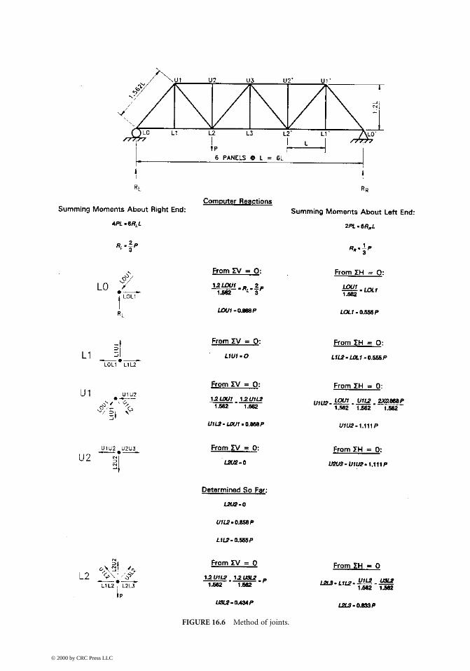
FIGURE 16.6 Method of joints.
© 2000 by CRC Press LLC

FIGURE 16.7 Method of sections.
FIGURE 16.8 Influence lines for forces in one chord and one diagonal.
© 2000 by CRC Press LLC

16.3.2 Computer Methods
The method of joints and the method of sections identified above appear to be very simple as longas the geometry of the truss is also simple and the structure is statically determinate. This isparticularly true if one or both chords are horizontal. On most modern trusses, the span is suffi-ciently long that the change in vertical geometry can be significant. In fact, most larger trusses areon vertical curves if they cross a waterway. The chord joints are usually parallel to the deck profile.Thus, in many practical truss bridges, one or both truss chords is a series of chord segmentsrepresenting a parabolic curve over at least part of the length of the bridge. This significantlycomplicates the geometry with respect to the use of either the method of joints or the method ofsections. It does not negate the use of either of these methods, but certainly makes them lessattractive.
There are many software packages for computers which permit the analysis of trusses, as can bedone typically as either the pin-connected assemblage or as a frame with moment-resisting joints.
If the bridge is determinate in the plane of a truss, and if the truss is analyzed with two forcemembers, then the cross-sectional area of the members does not affect the analysis. Assuming unitarea for all members will give the proper forces, but not necessarily the proper displacements. Ifthe truss is indeterminate in a plane, then it will be necessary to use realistic areas for the trussmembers and may be important to include the camber of the members in order to get realisticresults in some cases. This will be true of the so-called “geometric case” which is usually taken asthe state of the bridge under all dead load, at which time it is supposed to have the proper gradesand profile. An analysis for a subsequent load, such as unit loads for the assembly of influence lines,or a transient load, does not require inclusion of the member camber. In fact, inclusion of thecamber for other than the loads acting in the geometric condition would yield erroneous resultsfor the indeterminate truss.
Where software contains the ability to put in a unit length change within a member and ananalysis similar to this will be required to account properly for camber of the members, then it isoften found efficient to calculate the influence lines for truss members using the Mueller–Bresslauprinciple as found in any text on structural mechanics.
When a truss is analyzed as a three-dimensional assemblage with moment-resisting joints, thenthe method of camber becomes even more important. It is common practice for some of themembers to be cambered to a “no-load position” and in order for these members to have no loadin them as analyzed, all the other members in the truss will have to be properly cambered in thecomputer model. With the usual fabrication techniques and adequate care for camber in bothprimary and secondary member (which may have no camber), a three-dimensional computeranalysis of a roadway truss will typically result in determining truss member forces which are veryclose to those obtained by the pin-connected truss analogy. The secondary stresses from jointrotation resulting from transient loads will be determined directly from the computer analysis.
16.4 Floor Systems and Framing Details
16.4.1 Conventional Deck Systems Not Integral with Truss Chords
Initially, floor system framing was intended to be as structurally simple as possible. In the past,floor beams were often hung from truss pins with yokes, the simple-span stringers framing betweenfloor beams often supported by saddle brackets on floor beam webs. As time went on, the advantagesof continuous stringers, particularly in highway bridges, became very evident, and framing involvingstringers-over-floor-beams developed, as did improved details for framing simply supported string-ers between floor beams. Composite design of stringers and/or stringers and floor beams continuedto add strength, stiffness, and robustness to trusses, while simultaneously eliminating many of the
© 2000 by CRC Press LLC

sources of uncontrolled drainage, and hence, corrosion, which have been the perceived source ofexcessive maintenance in trusses. Currently, floor beams are either vertical or set normal to roadwaygrade, and stringers are usually normal to crown and parallel to grade. If they are vertical, somesort of beveled fill will be necessary between the floor beam and the stringers. A typical through-truss cross-section is shown in Figure 16.9.
Most modern truss designs continue to use concrete decks, as well as filled grid, or grid andconcrete composite systems as efficient durable decks. Relatively little use has been made of ortho-tropic decks in conjunction with original design (as opposed to rehabilitation) of trusses in theUnited States but this is certainly a feasible alternative. The use of newer lightweight deck systems,such as the proprietary Aluma-Deck or possibly advanced composite orthotropic deck systems canlead to further reduction in weight and, hence, savings in a competitive environment, as well asholding the potential for significantly reduced maintenance in future trusses.
FIGURE 16.9 Typical truss cross-section.
© 2000 by CRC Press LLC

16.4.2 Decks Integral with Truss Chords
So far, deck systems have almost always been designed to be structurally separate from the mainsupporting truss systems. As the need for efficiency and reduced cost, as well as increased redun-dancy, continues, a possible merging of the deck and truss system is a technical possibility. Anorthotropic deck has been used as part of the bottom or top chord on some foreign bridges.Redundancy issues should be thoroughly considered as more traditional load paths are reduced.The available computer capabilities allow modeling of damage scenarios and the emerging knowl-edge on the computation of reliability indexes for damaged structures can provide designs withhigh levels of confidence, but such sophisticated calculations will have to be justified by cost savingsand/or other benefits. Merging chords and deck has the potential to eliminate more joints withinthe deck system, perhaps at the expense of accommodating certain differential temperature features.Generally, as in all types of bridge structures, the elimination of joints is perceived as a favorabledevelopment. If the use of orthotropic decks as part of the chord system, and the lateral system forthat matter, were to evolve, designers would have to consider the possibility of using either reinforcedor prestressed concrete in a similar manner. This would, of course, tend to lead toward loading thechord at other than the panel points, but this situation has been handled in the past where, in somesituations, deck chord members directly supported the roadway deck over their full length, notsimply at the panel points.
16.5 Special Details
16.5.1 Hangers and Dummy Chords for Cantilever Bridges
The cantilevered truss has been used effectively on long-span structures since the Firth of ForthBridge was built in Scotland in the late 1800s. This structural system was developed to provide mostof the economy of continuous construction, as well as the longer spans possible with continuity,while simultaneously providing the simplicity of a statically determinate structural system. Considerthe system shown in Figure 16.10. Figure 16.10a shows what appears to be a Warren truss config-uration for a three-span continuous unit. The parallel diagonal configuration shown in the detailin Figure 16.10a is an indication that the framing system for the standard Warren truss has beeninterrupted. The statical system for the cantilever truss, indicated by the parallel diagonals, is shownin Figure 16.10b. The continuity has been interrupted by providing two points along the structurewhere the chords carry no axial force, resulting in a “shear only” connection. This is, by definition,a structural hinge. The unit between the two hinges is commonly referred to as a “suspended span.”The remaining portions of the structure are called the “cantilever arms” and the “anchor spans,” asindicated in Figure 16.10a. The mechanism for supporting suspended span is shown in concept inFigure 16.10c, which indicates that two chords are missing and hinges have been placed in the strap, orhanger, carrying the load of the suspended span into the anchor arm. The configuration with the linkand two hinges allows the portions of the structure to expand and contract relative to each other.
In practice, the unnecessary top and bottom chords are added to the structure to allay publicconcerns, and are articulated in a manner which prevents them from carrying any axial load. Theseelements are typically called “false chords, or “dummy chords.” A typical top chord joint at thehanger point is shown in Figure 16.11. Figure 16.11a is a plan view of the top chord element, andthe corresponding elevation view is shown in Figure 16.11b. The false chord in this case is supportedby the anchor arm, utilizing a pin. The false chord is slotted, so that it may move back and forthwith expansion and contraction without carrying any load. It simply moves back and forth relativeto the pin in the slot provided. The pin carries the vertical weight of the member to the top chordjoint. Also shown in Figure 16.11b, and extending further into Figure 16.11c, are details of thehanger assembly and the top pin of the pins in the hanger used to allow it to swing back and forth.Hangers are potentially fracture-critical members, as a failure of this member would almost certainly
© 2000 by CRC Press LLC

result in a collapse of at least the suspended span portion of the structure. These members areusually built of multiple components to add redundancy. The particular assembly shown hasmultiple plates bolted together to compensate for the hole occupied by the pin. In recent years,many truss bridges have been retrofitted with redundancy-adding assemblies usually consisting ofrods or cables parallel to the hanger and attaching to the top and bottom chord. These assembliesare intended to pick up the load if the hanger or pin were to fail. Some of the details for the hangerpin are also shown in Figure 16.11c.
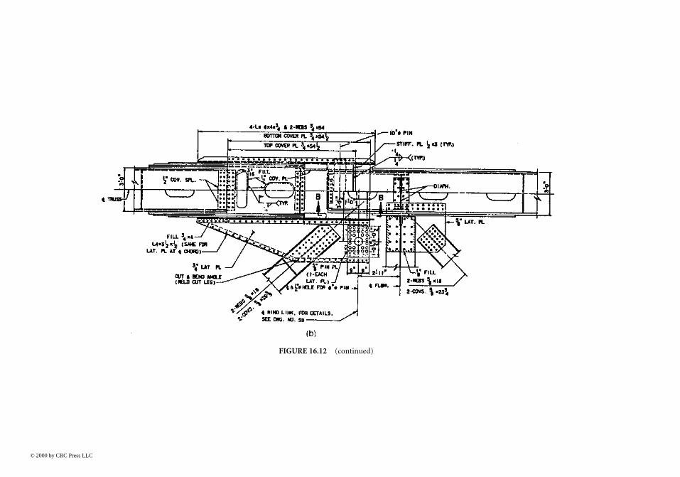
The corresponding portions of the structure at the bottom chord are shown in Figure 16.12. Anelevation view of the lower chord joint is shown in Figure 16.12a, and a partial plan view is shownin Figure 16.12b. The concepts are very similar to those utilized in the upper joints, in that thereare pins and slots to allow the false chord to move without picking up the axial load and pins andgusset plates to transfer the load from the suspended span into the hanger.
After completion of erection of the anchor span and the cantilever arm, the suspended span maybe erected component by component, often referred to as “stick erection,” or the entire suspendedspan may be assembled off site and hoisted into position until it can be brought into bearing at thehanger pins. If stick erection is used, the bridge will sag toward the middle as the cantilevers reachmidspan. The bridge will be in the sag position because, once assembled to midspan, the cantileverswill be much shorter than they are at the midspan closure. It will thus be necessary to raise or lowerportions of the bridge in order to get the closure members in and to transfer loads to the intendedstatical system. Also during this time, the false chords have to carry loads to support the cantile-vering. With this type of erection, the false chords may be temporarily fixed, and one or both ofthe chords may have mechanical or hydraulic jacks for transferring load and for repositioning thetwo cantilevers for closure. Provisions for this type of assembly are often made in the false chord,at least to the point of being certain that the required space is available for jacks of sufficient capacityand that bearing plates to transmit the load are either in place or can be added by the contractor. A
FIGURE 16.10 Cantilever suspension.
© 2000 by CRC Press LLC

typical detail for providing for jack assemblies is shown in Figure 16.13, which indicates how jackswould fit in the bottom false chord shown in Figure 16.12, and bear against the rest of the structure,so as to swing the cantilevered portion of the suspended span upward to facilitate closure.
16.5.2 Bearings
From the viewpoint of bearings, the cantilever form of erection offers several other advantages. Thebearings used on the main piers can be fixed to the pier tops, and the chords framing into thatpoint can be pinned into gusset plates. This provides a very simple and relatively maintenance-freeconnection to carry the major reaction of the bridge. The bearings on the end piers at the ends ofthe anchor spans are sometimes unique. Depending upon the requirements of the site or to reducecosts, the end spans are sometimes quite short, so that even under dead load, the reaction on theend piers is negative, which is to say an uplift condition exists under the dead load. Under somepatterns of live load, this uplift will increase. When this condition exists, hanger assemblies similarto those described in Section 16.5.1 may be used to connect to a bearing fixed to the pier, andconnected to an embedded steel grillage or similar device used to engage the weight of the pier tohold down the superstructure. Such a bearing is shown in Figure 16.14. The link accommodates
FIGURE 16.11 (a) Top false chord details — plan view; (b) top false chord details — elevation view; (c) hangerdetails.
© 2000 by CRC Press LLC

the movement of the superstructure relative to the substructure required by expansion and con-traction. The length of the arch swing of the link is designed so that the vertical displacementassociated with the swing of the link can be accounted for and accommodated.
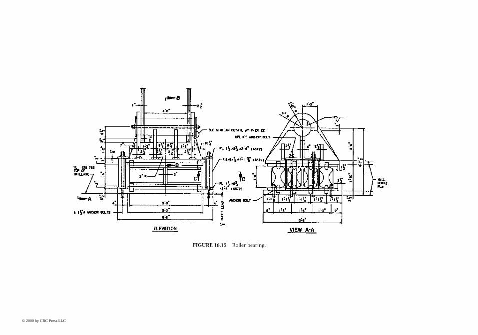
Where positive reactions are possible under all loadings, the bearing on the back span pier maybe a rocker, roller nest, such as that shown in Figure 16.15, roller and gear assembly, or low-profilemodern bearings, such as a pot bearing shown in Figure 16.16 as applied to a girder bridge or thedisk bearing shown in Figure 16.17. It will usually be necessary for this bearing to provide forexpansion and contraction while minimizing the forces put on the piers and to allow for rotationabout the major bending axis of the bridge. Depending upon the designer’s preferences, these bearingsmay or may not also carry the horizontal forces on the structure, such as wind loads, into the piers inthe transverse direction. In some instances, the chord bearings serve this function through guide barsor pintles and, in some cases, a separate wind bearing, such as that shown in Figure 16.18, is providedto carry the transverse loads into piers separate from the main chord bearings.
Where structures are continuous, as opposed to cantilevered, it will usually be necessary for threeof the four span bearings supporting the typical three-span truss to move. Individual movementwill be greater in these bearings than they would be for a comparable-length cantilevered truss, andadditional requirements will be placed on the bearing at one of the two main piers which moves,because of the large vertical reaction that will be transmitted at that point. Additionally, the con-tinuous bridge will have two expansion joints, instead of four on the cantilever bridge, which isboth an advantage and a disadvantage. These joints will have to be larger for the continuous bridgethan for the cantilevered bridge and, therefore, more expensive. On the other hand, the tendencytoward minimizing the number of joints in structures in order to reduce damage from deck drainagefavors the continuous structure. Generally speaking, the extra points of expansion and contraction,associated deck joints and articulation hardware in the cantilevered bridge have required above-average maintenance.
FIGURE 16.11 (continued)
© 2000 by CRC Press LLC

16.5.3 Wind Tongues and Bearings for Transverse Forces
Wind loads carried by the suspended span in the cantilevered bridge have to be carried to thebearings on the piers. Thus, it is necessary for the wind loads to be carried through the panelsframed with the false chords. Typically, in a through-truss, all of the wind loads on the suspendedspan are reacted by the hangers and by a special-purpose mechanism used to transmit horizontalforces at the lower chord level from the suspended span into the anchor arms. Wind load tributaryto the upper lateral truss system in the plane of the top chord joints is carried into the anchor armsas a shear at the lower chord joint and the torque necessary to react to the transfer of loads fromthe top chord to the lower chord is carried as equal and opposite vertical reactions on the hangers.The horizontal forces at the lower chord level are then transmitted from the suspended span to thecantilever arm by a device called a “wind tongue,” shown schematically in Figure 16.19. Because ofthe offset in chord joints at the suspended span, the horizontal force creates a torque in the planeof the bottom lateral system as the shear is transmitted across the expansion joint. Additionally,because expansion and contraction movements are accommodated at this point, allowance has tobe made for some of the lateral members to swing along with that expansion and contraction. Thus,in Figure 16.19, there are four pin assemblies shown in the detail. The two horizontal links thusswing back and forth to accommodate the relative movement occurring at the open joint. Thetorque caused by the offset shear is reacted by the members framing from the open joint back into
FIGURE 16.12 (a) Bottom false chord details — elevation view; (b) bottom false chord details — plan view.
© 2000 by CRC Press LLC
)
© 2000 by CRC Press LLC
FIGURE 16.12 (continued

the next panel point of the suspended span. These members form a lever to react to torque andprevent significant rotation of the wind tongue.
The typical details for accomplishing this wind transfer are shown in Figure 16.20a and b.Figure 16.20a shows the assembly that spans the open joint between the suspended span and theanchor arm. Also shown is one of the horizontal link members. The reacting members that formthe lever to react the torque are also shown in this view, and are shown again in Figure 16.20b asthey converge back to a common work point in the lateral truss of the suspended span. A typicalpin assembly is shown in Figure 16.21.
In the case of the continuous truss, since the open joint does not exist, no assembly similar tothe wind tongue, described above, is necessary. As can be seen in a plan view, the colinear forcesystem can be developed to transmit wind and other transverse forces into the piers without creatingtorque in the bottom lateral system. Despite this, designers will often support the bearing point inorder to accommodate accidental eccentricies that might exist. As seen in a vertical plane, there willalmost certainly be an eccentricity between the center of transverse forces and the bearing. This willalso be typically framed into a triangular system to carry this eccentricity through truss action,
FIGURE 16.13 False chord jacking details.
© 2000 by CRC Press LLC

rather than bending. These details are usually much simpler than the wind tongue at the suspendedspan, because it is not necessary to account simultaneously for expansion and contraction in thelateral truss system. This is usually handled by allowing the reaction points to move relative to thebearing while they are stationary relative to the lateral truss.
16.6 Camber and Erection
16.6.1 Camber for Vertical Geometry
It is obvious that all bridges have a theoretical geometric location as determined by the final designdrawings. Every member has a theoretical length and location in space. One goal of the designer,fabricator, and erector is to produce a bridge as close to the theoretical position as possible, therebyensuring actual stresses similar to design stresses.
To accomplish this, main members are usually cambered. Tensioned members that stretch underload are fabricated, such that their unstressed length is shorter than their length under the effect ofdead load of the structure. The opposite is true for compression members. The cambered lengthsare then accounted for during the erection stress and geometry studies. The state of the bridge whenthe camber “comes out” is called the geometric position. In this state the loads on the bridge aresufficient to return all of the members to their theoretical length. At any other state, the bridge willbe out of shape and additional forces may result from the difference between its shape at any timeand the final shape. This is relatively easy to see in the case of a continuous truss because it is clearlystatically indeterminant and the shears and moments producing member forces are dependent on
FIGURE 16.14 Link-type tie-down bearing.
© 2000 by CRC Press LLC
ing.
© 2000 by CRC Press LLC
FIGURE 16.15 Roller bear

FIGURE 16.16 (a) Typical pot bearing; (b) typical pot bearing details.
© 2000 by CRC Press LLC

its shape. However, this is also true for a simple span truss because the joints are not frictionlesspins as may have been assumed in the analysis. Because of this, even the simplest form of truss canhave significant temporary member forces and moments until it reaches the geometric position. Aswill be discussed in the next section, there may be secondary moments in the geometric position,depending on the positioning of connector patterns on member ends in the shop.
Secondary members such as laterals and sway frame members are usually not cambered. Theyare usually intended to be stress free in the geometric position. Thus, at intermediate stages oferection they may also be subject to temporary forces.
FIGURE 16.17 Typical disc bearing.
© 2000 by CRC Press LLC

© 2000 by CR
FIGURE 16.18 Truss wind bearing.
C Press LLC

The importance of camber in achieving the designer’s intent for the structure will be shown inthe following discussion. In a determinant structure, the forces in components are uniquely deter-mined by the geometry, loading, and support condition through the equations of equilibrium. Thedesigner cannot alter the structural actions.
In a redundant structure, the designer can alter the forces associated with any one loading case.After this, the distribution of forces is again uniquely determined by all the conditions above, plusthe relative stiffness of the various structural components.
Consider a simple case. If a two-span simply supported beam supporting a uniform load isintended to be horizontal under that load, the natural order is to have the reactions and negativemoment at the pier equal to the value shown below at Piers 1, 2, and 3, respectively.
(16.1)
(16.2)
(16.3)
Given the reactions, the load and length of the beam, the deflection at any point of the beam canbe determined. Given that the example started with the condition that the beam is to be horizontal,calculation of deflections would reveal that the deflection is zero at all three support points andthat the beam deflects downward between the support points. In order to put the beam on ahorizontal position under a load, the web plates must be cut to the reverse of the deflected shape.
An alternative set of reactions and a corresponding moment diagram can be determined for thisbeam by cambering it so that not all three support points are on a straight line. For example, supposeit was desired to reduce the negative moment at the center pier. This could be achieved by cuttingthe web plate such that, in the horizontal layout position, the girder would rest such that a straightline between the two external reactions would be below the middle of the beam (with gravity actingdownward). Thus, when the beam is assembled in the field, a certain amount of bending will have
FIGURE 16.19 Schematic of wind tongue.
R
wR1 3
38
= =l
R
w2
108
= l
M
w2
2
8= l
© 2000 by CRC Press LLC

to take place as a simply supported beam of span equal to 2L until such time as the girder touchesthe middle bearing. After that, the remainder of the loads will be carried as a two-span unit. Unlessa loading is sufficient in magnitude and opposite in sense so as to create uplift at the center bearing,all loads will then be handled as a two-span continuous unit. In this way, one might determine thatan optimum condition is to have equal dead-load moments in the two spans and over the support.All that is necessary to achieve this is to determine the offset distance off the bearing point in thelaydown position. Then cut the beam to that configuration using the cambered shape and erect it.
In truss construction, this adjustment of natural forces is seldom actually done. On occasion,camber to produce a determinant structure at steel closure has been used to facilitate erection.Camber for force control is very common in other types of bridges.
16.6.2 Camber of Joints
When the principal operations on a main member, such as punching, drilling, and cutting arecompleted, and when the detail pieces connecting to it are fabricated, all the components are broughttogether to be fitted up, i.e., temporarily assembled with fit-up bolts, clamps, or tack welds. At thistime, the member is inspected for dimensional accuracy, squareness, and, in general, conformancewith shop detail drawings. Misalignment in holes in mating parts should be detected then and holesreamed, if necessary, for insertion of bolts. When fit-up is completed, the member is bolted orwelded with final shop connections.
The foregoing type of shop preassembly or fit-up is an ordinary shop practice, routinely per-formed on virtually all work. There is another class of fit-up, however, mainly associated withhighway and railroad bridges that may be required by project specifications. These may specify thatthe holes in bolted field connections and splices be reamed while the members are assembled inthe shop. Such requirements should be reviewed carefully before they are specified. The steps ofsubpunching (or subdrilling), shop assembly and reaming for field connections add significant costs.Modern computer-controlled drilling equipment can provide full-size holes located with a highdegree of accuracy. AASHTO Specifications, for example, include provisions for reduced shopassembly procedures when computer-controlled drilling operations are used.
16.6.3 Common Erection Methods
The most common construction methods for trusses include cantilever construction, falsework,float-ins, and tiebacks. It is common for more than one method to be used in the construction ofany single bridge. The methods selected to erect a bridge may depend on several factors, includingthe type of bridge, bridge length and height, type and amount of river traffic, water depth, adjacentgeographic conditions, cost, and weight, availability, and cost of erection equipment.
Regardless of the method of erection that is used, an erection schedule should be prepared priorto starting the erection of any long-span bridge. The study should include bridge geometry ,memberstress, and stability at all stages of erection. Bridges under construction often work completelydifferently than they do in their finished or final condition, and the character of the stress is changed,as from tension to compression. Stresses induced by erection equipment must also be checked, and,it goes without saying, large bridges under construction must be checked for wind stresses andsometimes wind-induced vibrations. An erection schedule should generally include a fit-up schedulefor bolting major joints and a closing procedure to join portions of a bridge coming from oppositedirections. Occasionally, permanent bridge members must be strengthened to withstand temporaryerection loads. Prior to the erection of any bridge, proper controls for bridge line and elevationmust be established and then maintained for the duration of the construction period.
Most long-span bridge construction projects have a formal closing procedure prepared by bridgeengineers. The bridge member or assembled section erected to complete a span must fit the longitudinal
© 2000 by CRC Press LLC

opening for it, and it must properly align with both adjoining sections of the bridge. Properalignment of the closing piece is generally obtained by vertical jacking of falsework, lifting theexisting bridge with a tieback system, or horizontal jacking of truss chords. At the Greater NewOrleans Bridge No. 2, a scissors jack was inserted in place of a dummy top chord member, and itwas used to pivot the main span truss for proper alignment.
FIGURE 16.20 (a) Details of wind bearing; (b) details of wind tongue.
© 2000 by CRC Press LLC

© 2000 by CRC Press LLC
FIGURE 16.20 (continued)

FIGURE 16.21 Typical wind tongue pin details.
FIGURE 16.22 Cantilever erection.
© 2000 by CRC Press LLC

16.6.3.1 Cantilever ConstructionIn balanced cantilever construction, a bridge cantilevers in both directions from a single pier, asshown in Figure 16.22. The loads on each side of a pier must be kept reasonably in balance. In thistype of construction, the first horizontal member erected in each direction may have to be tempo-rarily supported by a brace, as shown in Figure 16.23.
In other types of cantilever construction, one span of a truss may be complete, and the bridgethen cantilevers into an adjacent span, as shown in Figure 16.24. This type of construction is quitecommon.
16.6.3.2 FalseworkFalsework is commonly used when building medium-span trusses, especially for bridge approachesover land, as shown in Figures 16.25 and 16.26. It is also used in long-span bridge construction,but heavy river traffic, deep water, or poor foundation material may restrict its use. Falsework issometimes used in the anchor or side span of cantilever trusses.
16.6.3.3 Float-InFloat-in is another commonly used construction method for long-span bridges. In this method, aportion of the bridge is generally assembled on a barge. The barge is then moved to the constructionsite, and the bridge is then either set into place off the barge or pulled vertically into place from thebarge and connected to the part of the bridge already constructed. This method was used on thesecond Newburgh–Beacon Bridge across the Hudson River as discussed below.
First, a short section of the main span truss was erected on a barge; then sections of the approachspans over the river were assembled on top of the main span truss, floated into position, and erected,as shown in Figures 16.27 and 16.28. The section of bridge floated in is generally higher than itsfinal position, and it is lowered into position with jacks. The two anchor spans were then assembledon a barge and erected the same way, as shown in Figure 16.29.
FIGURE 16.23 Early stage.
© 2000 by CRC Press LLC

The cantilever portion of the bridge was then erected member by member by the cantilevererection method out into the main span to the pin hangers, as shown in Figure 16.30, which alsoshows the arrival of the suspended span of the main span. The suspended span was then bargedinto position and hoisted in place as shown in Figure 16.31.
FIGURE 16.24 Advanced stage of cantilevering.
FIGRE 16.25 Use of falsework — 1.
© 2000 by CRC Press LLC

The forces obtained during various stages of construction may be entirely different from thoseapplicable to the final condition, and, in fact, the entire mechanism for resisting forces within thestructure may change. During the erection of a truss, falsework bents may be used to support aportion of the structure. The gravity and lateral loads still act in the sense that they do on the final
FIGURE 16.26 Use of falsework — 2.
FIGURE 16.27 Float-in — 1.
© 2000 by CRC Press LLC

condition, and the basic internal mechanism of resisting forces, as outlined in Chapter 10 of theStandard Specifications or Section 6 of the AASHTO-LRFD Specifications, remains unchanged, i.e.,the primary load path involves axial load in the chords and diagonals, with the vertical componentsof those forces adding up to equal the applied shear within the panel, and the bending momentaccounted for by the horizontal component of those forces. The camber of the truss will not pertain
FIGURE 16.28 Float-in — 2.
FIGURE 16.29 Float-in — 3.
© 2000 by CRC Press LLC

to an intermediate construction case, and, therefore, there is apt to be more joint rotation and,hence, more secondary bending moments within the truss members. Nonetheless, the primary load-carrying mechanism is that of axial forces in members. As the truss is erected, it is entirely possiblethat members that are in tension in the permanent condition will be under compression duringerection, and vice versa. In fact, the state of stress may reverse several times during the erection ofthe bridge. Clearly, this has to be taken into account, not only in the design of the members, butalso in the design of the connections. Compression members are apt to have been designed totransmit part of the forces in bearing. This will not be applicable when the member is in tensionduring erection. Similarly, a compression member that has tension during erection has to bereviewed for net section provisions and shear lag provisions.
FIGURE 16.30 Float-in of suspended span.
FIGURE 16.31 Lift of suspended span.
© 2000 by CRC Press LLC

16.7 Summary
Truss bridges have been an effective and efficient force of long-span bridges for over 150 years. Asplate girder bridges have been utilized for spans of about 550 ft, box girders for spans of up to 750ft, segmental concrete box girders for spans of up to about 800 ft, and cable-stayed bridges for spansof about 500 feet to 2000 ft, the use of trusses has declined over the last 25 years. Nonetheless, theyremain a cost-effective bridge form, one with which many fabricators and erectors are experienced.Emerging materials and the use of computer analysis to treat the bridge as a three-dimensionalstructure will keep the truss form viable for the foreseeable future.
References
1. Historic American Engineering Record, National Park Service, Washington, D.C., 19762. Hartle, R. A., Amrheim, W. J., Willson, K. E., Baughman, D. R., and Tkacs, J. J., Bridge Inspector’s
Training Manual/90, FHWA-PD-91-015, Federal Highway Administration, Washington, D.C.,1990.
© 2000 by CRC Press LLC