kurz instruments inc. kurz instruments, inc. series...
TRANSCRIPT
Kurz Instruments Inc.
Series 2440 User’s Guide 1 DCN: 360202-1.0 Rev. 5
Kurz Instruments, Inc.
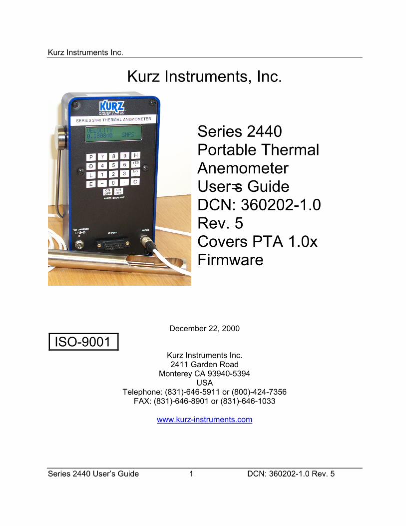
Series 2440Portable ThermalAnemometerUser=s GuideDCN: 360202-1.0Rev. 5Covers PTA 1.0xFirmware
December 22, 2000
ISO-9001Kurz Instruments Inc.2411 Garden Road
Monterey CA 93940-5394USA
Telephone: (831)-646-5911 or (800)-424-7356FAX: (831)-646-8901 or (831)-646-1033
www.kurz-instruments.com
Kurz Instruments Inc.
Series 2440 User’s Guide 2 DCN: 360202-1.0 Rev. 5
Publication Notices
COPYRIGHTCOPYRIGHT8 2000. All rights are reserved. No part of this publication may be storedin a retrieval system, transmitted or reproduced in any way, including but not limited tophotocopy, photograph, magnetic or other record, without the prior agreement andwritten consent of Kurz Instruments, Inc.
TRADEMARKSMetalCladJ, Series 2440 are trademarks of Kurz Instruments, Inc. Hyper Terminal,Windows 95/98/NT are trademarks of Microsoft Corporation. Modbus is a trademark ofModicon, a Group Schneider company.
PUBLICATION NOTICEEvery effort has been made to supply complete and accurate information to thecustomer. However, Kurz Instruments, Inc. assumes no responsibility for its use, norany infringements of patents or other third parties which would result. In addition, KurzInstruments, Inc. makes no representations or warranties of any kind concerning thecontents of this publication. Under no circumstances will Kurz Instruments, Inc. be heldliable for any loss or other damages pertaining to the use of this publication.
This publication is generic in nature. No guarantee is made that this publicationconforms to the particular equipment produced for a particular application. As-builtpublications entail an additional charge. Factory and on-site training in the use andoperation of Kurz Instruments, Inc. products may be made available at the buyer=sexpense, subject to agreement by Kurz Instruments, Inc.
The information contained in this publication is subject to change without notice. KurzInstruments, Inc. reserves the right to make engineering changes and productimprovements at any time and without prior notice. Consult your local Kurz Instruments,Inc. Representative or a Factory applications engineer for information regarding currentspecifications.
Kurz Instruments, Inc. assumes no liability for damages or injuries (consequential orotherwise) caused by the improper use and/or improper installation of this product orwhere this product is used in any application other than what it was designed for andintended. Kurz Instruments, Inc. expressly denies any responsibility if this product hasbeen modified without Kurz Instruments, Inc.=s written approval or if this product has
Kurz Instruments Inc.
Series 2440 User’s Guide 3 DCN: 360202-1.0 Rev. 5
been subjected to unusual physical or electrical stress, or if the original identificationmarks have been removed or altered.
Equipment sold by Kurz Instruments, Inc. is not intended for use in connection with anynuclear facility or activity unless specifically sold for such applications and specificconditions for such usage are detailed. If the equipment is used in a nuclear facility oractivity without supporting quotation, Kurz Instruments, Inc. disclaims all liability for anydamage, injury, or contamination, and the buyer shall indemnify and hold KurzInstruments, Inc., its officers, agents, employees, successors, assigns, and customers,whether direct or indirect, harmless from and against any and all losses, damages, orexpenses of whatever form and nature (including attorneys fees and other costs ofdefending any action) which they, or any of them, may sustain or incur, whether as aresult of breach of contract, warranty, tort (including negligence), strict liability or othertheories of law, by reason of such use.
Kurz Instruments Inc.
Series 2440 User’s Guide 4 DCN: 360202-1.0 Rev. 5
Kurz Instruments Inc.2411 Garden Rd.Monterey, CA 93940-5394USATelephone: 831-646-5911 or 800-424-7356FAX: 831-646-8901 or 831-646-1033www.kurz-instruments.com
Document Title: Series 2440 Portable Thermal Anemometer User=s Guide,PTA 1.0x
Document Number: 360202-1.0, Revision 5Publication Date: December 22, 2000

ORDERS Al l orders are received subject to acceptance by KURZ INSTRUMENTS, INC. at the factory in Monterey, CA, U.S.A., herein referred to as COMPANY, and may be acceptedonly on Company’s pr inted acknowledgement form. Purchase orders for Company productsand services must be made out to the Company and must be received in writing at Monterey, CA before performance is completed unless otherwise approved by the company.
QUOTATION AND PUBLISHED PRICES Until acceptance, all written quotationsare subject to change upon written notice to the buyer and are void after 30 days unless oth-erwise specified on quote. Verbal quotations are good only on the day on which they aremade by an authorized representative of the Company.
The prices shown on the published price lists and other published literature issued by theCompany are not offers to sell and are subject to confirmation by specific quotation andacknowledgement. All published prices and discounts are subject to change without notice.
SEALED BIDS are subject to these Standard Conditions of Sale unless specified otherwisein bid and agreed to by the company.
TAXES Prices are exclusive of all foreign, federal, state, municipal or other governmentexcise, sales, use, occupational, duty, or like taxes now in force, or enacted in the future andtherefore are subject to an increase equal in amount to any tax the Company may berequired to collect or pay upon the sale or delivery of the items purchased.
TERMS The terms of sale shown in the published price list shall apply from the date ofshipment by the Company. If the Company in its judgment at any time deems that by reasonof the financial condition of the Buyer or otherwise the continuance of production or shipmenton the terms specified herein is not justified, the Company may require full or partial paymentin advance. Certain orders may, in the judgment of the Company, because of their nature orthe delivery involved, require progress payments. Pro rate payments shall become due asshipments are made. Terms are cash net 10 days. Amounts past due are subject to a servicecharge of 1-1/2% per month (or fraction thereof).
Should the Buyer be in default of the terms stated above, the Company shall add to theBuyer’s account, all reasonable costs, including attorneys’ fees, filing fees and any other feesor expenses deemed reasonable by the Company in collecting the amounts due.
PACKING The Company makes no charge for its standard packing for domestic ship-ment. The Buyer may be charged for export packing or other special packing required, thecost of which will be quoted upon request. No credit or deduction will be allowed if no packingis required.
DELIVERY Shipping dates given by the Company are approximate and are based onprompt receipt of all necessary information regarding the order. The company will use its bestefforts to meet the ARO date provided the Buyer supplies all necessary information and datapromptly, but cannot be held responsible for causes beyond its reasonable control.The Company shall in no event be responsible for loss of profits, damages incurred by thebuyer to its customers or other consequential damages resulting from Company’s failure todeliver within the time specified herein.
In the event of any delay requested by the Buyer or any delay caused by lack of shippinginstructions, the Company will store all items ordered at the Buyer’s risk and expense, andwill invoice the Buyer for the full contract price of the apparatus on or after the date on whichthe same is ready for delivery. If manufacture is delayed by the Buyer, payment shall be madebased on the percent of completion and the contract price.
SHIPPING COSTS AND INSURANCE Shipments are f.o.b. factory, Monterey, CA,freight and insurance prepaid and added, or freight collect unless otherwise requested andagreed to by the Company. If insurance is being provided by the Buyer a formal statement ofBuyer responsibility must accompany purchase order. Customer is responsible for notificationin writing to the Company within 72 hours of any loss or damage of the shipment if the ship-ment was made f.o.b. destination. In the absence of specific instructions, the Company willselect the carrier.
CHANGES The Buyer may from time to time, but only with the written consent of theCompany, make any change in the order. In the event of any such change, the Buyer shallpay to the Company the reasonable costs and other expenses (including engineering expens-es and all commitments to its suppliers and sub-contractors incurred by the Company prior toreceipt of notice of such change for all work rendered unnecessary by such change orincurred by the Company thereafter for all work required to effect such change. In either case,an amount determined by the Company in its discretion by applying to the amount such costsand other expenses and the Company’s usual rate of profit for similar work. In the event ofany such change, the Company shall further be entitled to revise its price and delivery sched-ules to reflect such change.
CANCELLATION In the event of cancellation, the Buyer shall be liable for the paymentof reasonable cancellation charges, which shall not exceed the unit retail list price of the itemscancelled and shall include among other things expenses already incurred by the Company,actual liabilities against Commitments incident to the order involved, and properly allowableindirect charges as well as a reasonable profit. No delivery delay requested by Buyer on anorder placed under this Agreement shall be effective unless covered by an amendment to theorder that provides for the payment of any agreed upon costs the delay imposes on theCompany and that is accepted on the Company’s printed acknowledgement form. Standardproducts only once delivered may be returned to the Company’s discretion and upon approvalfrom the Company in Monterey, CA, at a minimum charge for restocking of 20% of list price.Return shipping charges are of Buyer ’s expense.
If the Buyer makes an assignment for the benefit of creditors, if a voluntary or involuntarypetition or other action in bankruptcy or for reorganization or under any other insolvency lawshall be filed by or against the Buyer, if the Buyer shall admit inability to pay its debts, if atrustee, receiver or liquidator is appointed for any part of the assets of the Buyer, or if theBuyer fails to make payments to the Company in accordance with the terms hereof, theCompany may at its option cancel all undelivered parts of any order by written notice to theBuyer at no expenses to the Company.
ACCEPTANCE — PRODUCT Unless otherwise agreed to by the Company, the crite-rion for acceptance of the Company’s products including options shall be the successful oper-ation of the product and options using the Company’s standard test procedures applicable tothe product and options involved. All acceptance tests shall be run by Company personnel atthe Company’s factory, unless otherwise allowed for and agreed to by the Company.
LIMITED WARRANTY— PRODUCT (LIABILITY FOR REPAIR AND REPLACEMENT ONLY) The Company's prod- ucts are warranted to be free from defects in material and workmanship for one year from date of shipment from the factory. The Company’s obligation is limited to repairing, or at their option, replacing products and components which, on verification, prove to be defective, at the factory in Monterey, CA. The customer is responsible for materials of construction selec- tion and for materials suitability for the intended use of Kurz equipment. The Company shall not be liable for installation charges, for expenses of Buyer for repairs or replacement, for damages from delay or loss of use, or other indirect or consequential damages of any kind. The Company extends this warranty only upon proper use and/or installation of the product in the application for which intended and does not cover products which have been modified without the Company’s approval or which have been subjected to unusual physical or electri- cal stress, or upon which the original identification marks have been removed or altered.
Whenever the design of the equipment to be furnished of the system in which it is to be incorporated originate with the buyer, manufacturer ’s warranty is limited specifically to matters relating to furnishing of equipment free of defects in material and workmanship and assumes no responsibility for implied warranties of fitness for purpose or use.
Transportation charges for material shipped to the factory for warranty repair are to be paid by the shipper. The Company will return items repaired or replaced under warranty prepaid. No items shall be returned for warranty repair without prior authorization from the Company.
PATENT AND TRADEMARK INDEMNITY The Company will, at its own expense, defend any suit against the Buyer for the infringement of United States patents and trade- marks by products purchased from the Company and in any such suit will satisfy any final award for infringement: except that the Company assumes no obligation to defend or assume liability for damages (consequential or otherwise) resulting from infringements (a) of patent claims covering any other products or any contemplated equipment or any assembly, combi- nation, method or process, in which, or in the manufacture or testing of which any such prod- ucts purchased from the Company may be used (not withstanding that such products pur - chased from the Company may have been designed only for use in or may only be useful in such other patented products or such patented equipment, assembly, circuit, combinanation, method, or process, or in the manufacture or testing thereof and that such products pur- chased from the Company may have been purchased and sold for such use), or (b) resulting from designs supplied by the purchaser, or for any trademark infringement involving any mar- keting or branding applied by the Company or involving any marking or branding applied at the request of the buyer.
The indemnity is upon the condition that the Buyer give the Company prompt notice in writ- ing of any such suit for infringement or threat of such suit and full opportunity to conduct the defense thereof. No costs or expenses shall be incurred for the account of the Company with- out its written consent. At its option, the Company may, at any time, replace or modify any products sold under this contract to avoid patent or trademark infringement provided such replacement or modification does not materially affect performance. The Company’s liability under this indemnity shall not exceed the purchase price of the infringing product.
DOCUMENTATION AND TRAINING In no event shall orders be accepted where payment is contingent on provision of documentation, unless agreed to in advance. Documentation is generic in nature, no guarantee is made that the documentation conforms to the equipment produced as built. As built documentation entails an additional charge.
The Company will supply reasonable written documentation including operator instructions. Factory and on-site training in use and operation of the Company’s products may be made available at Buyer’s expense, subject to acceptance by the Company.
PROPRIETARY RIGHTS Kurz Instruments, Inc. proprietary rights are included in infor- mation disclosed in instruction manuals, user guides, drawings and quotations or any other document or information disclosed. No Kurz document or information disclosed therein shall be reproduced or transferred to other documents or used by others for manufacturing or for any other purpose except as specifically authorized in writing by Kurz Instruments, Inc.
SUBSTITUTIONS AND MODIFICATIONS The Company assumes the right to make substitutions and modifications in the specifications of equipment designed by the Company providing that such substitutions or modifications will not materially affect perfor- mance in the intended application.
TOOLS The Company shall retain title to and possession of any models, patterns, dies, molds, jigs, fixtures and other tools made for or obtained in connection with this contract unless otherwise agreed to by the Company.
CONSTRUCTION All quotations are made and all orders are accepted by the Company with reference to the laws of the State of California, the rights and duties of all persons and the construction and effect of all provision thereof shall be governed by and construed accord- ing to the laws of the state.
Should any term or provision contained in these conditions contravene or be invalid under applicable law, the contract of which these conditions form a part shall not fail by reason thereof but shall be construed in the same manner as if such terms or provision had not appeared herein.
REGULATORY LAWS AND / OR STANDARDS The Company makes no promise or representation that its product will conform to any state or local laws, ordinances, regulations, codes or standards, except as particularly specified and agreed upon for compli- ance in writing as part of the contract between Buyer and the Company. The Company’s prices do not include the cost of any related inspections or permits or inspection fees.
EXCUSABLE CESSATION OF PERFORMANCE FOR NON-PAYMENT Whenever Buyer fails to meet the payment requirements set forth in this condition, manufac- turer may cease performance and delivery and accelerate payment of any and all unpaid charges, such cessation of performance shall not be construed to be a breach of any contract or agreement and manufacturer will resume production as soon as reasonably possible upon receipt of payment of all balances due.
NUCLEAR QUALIFICATION Equipment sold by Kurz Instruments, Inc. is not intend- ed for use in connection with any nuclear facility or activity unless covered by a specific quo- tation where the conditions of such usage will be detailed. If equipment is used in a nuclear facility or activity without a supporting quotation, Kurz disclaims all liability for any damage, injury or contamination, and the buyer shall indemnify and hold Kurz, its officers, agents, employees, successors, assigns and customers, whether direct or indirect, harmless from and against any and all losses, damages or expenses of whatever form or nature (including attor- ney’s fees and other costs of defending any action) which they, or any of them, may sustain or incur, whether as a result of breach of contract, warranty, tort (including negligence), strict liability or other theories in law, by reason of such uses.
Standard Conditions of Sale of Kurz Products
The Leader in Mass Flow Flow Technology for Process and Environmental MeasurementsKurz Instruments, Inc. • 2411 Garden Road, Monterey, CA93940 • 800-424-7356 • 831-646-5911 • FAX 831-646-8901email: [email protected] • www.kurz-instruments.com DCN 28050 Rev. D
Kurz Instruments Inc.
Series 2440 User’s Guide 6 DCN: 360202-1.0 Rev. 5
Table of Contents
Publication Notices........................................................................................................................................................2COPYRIGHT ...........................................................................................................................................................2TRADEMARKS .......................................................................................................................................................2PUBLICATION NOTICE .......................................................................................................................................2
INTRODUCTION.............................................................................................................. 9
Important Issues for Accurate Flow Measurements ..................................................................................................9
BASIC OPERATION ...................................................................................................... 11
Navigating the Menus .................................................................................................................................................12Selecting Menus .......................................................................................................................................................12Entering Data............................................................................................................................................................12Clearing Data, Editing Data or Exiting Menus.........................................................................................................13Holding a Menu For Display....................................................................................................................................13Help Display.............................................................................................................................................................13
Flow Meter Time Constant ........................................................................................................................................13
Data Logging ...............................................................................................................................................................14External Data Logging .............................................................................................................................................14Internal Logging .......................................................................................................................................................15
Calibration...................................................................................................................................................................15Calibration of the Analog Output .............................................................................................................................15Calibration of the Analog Input................................................................................................................................16
External Communications To The Portable .............................................................................................................16Modbus Industrial Network Protocol .......................................................................................................................16
Battery Discharge, Charge and AC powered ...........................................................................................................17Externally Powered ..................................................................................................................................................18Charge Status............................................................................................................................................................18
Configuration Data Storage .......................................................................................................................................19Configuration, Upload/Download ............................................................................................................................20
PROGRAM MODE ......................................................................................................... 23
Functions Available in Program Mode .....................................................................................................................23Set System Units..................................................................................................................................................23Reset Totalizer.....................................................................................................................................................23Set Time and Date ...............................................................................................................................................23Set ADC Sample Rate .........................................................................................................................................23
Kurz Instruments Inc.
Series 2440 User’s Guide 7 DCN: 360202-1.0 Rev. 5
Flow Calibration Data .........................................................................................................................................24METER 1 Velocity Parameters ...........................................................................................................................24METER 2 Flow Rate Parameters ........................................................................................................................24METER 3 Temperature Parameters.....................................................................................................................24Set METER Filter TC..........................................................................................................................................24Calibration of the 4-20 mA outputs .....................................................................................................................24Set Alarms ...........................................................................................................................................................25Load Calibration Data from EEPROM................................................................................................................25Set Communications Mode..................................................................................................................................25Set Baud Rate ......................................................................................................................................................26Set Data Logging .................................................................................................................................................26Set Memory Data Logging ..................................................................................................................................26Executive Mode Scroll ........................................................................................................................................26
Entering Program Mode ............................................................................................................................................26
Analog Output Range .................................................................................................................................................27
Analog Output Calibration ........................................................................................................................................28
Internal Memory Logging ..........................................................................................................................................29Memory Log Setup...................................................................................................................................................32Event and Min/Max Log Setup ................................................................................................................................32Trend Log Setup.......................................................................................................................................................32Test Log Setup .........................................................................................................................................................33
Accessing the Memory Log ........................................................................................................................................34Recording Event and Min/Max Data........................................................................................................................34Recording Trend Data ..............................................................................................................................................34Recording Test Data.................................................................................................................................................35Viewing Test Data Logs...........................................................................................................................................36
Exporting the Memory Log Data to PC....................................................................................................................37Exporting Event log data ..........................................................................................................................................38Exporting Trend log data..........................................................................................................................................39
Importing Trend Data to Excel ............................................................................................................................42Exporting Test log data ............................................................................................................................................43
FLOW CALIBRATION ................................................................................................... 48
Calibration of the 2440 ...............................................................................................................................................48
Using the 2440 for Field Calibration .........................................................................................................................48
TROUBLESHOOTING ................................................................................................... 50
RETURN SHIPMENT ..................................................................................................... 52
Kurz Instruments Inc.
Series 2440 User’s Guide 8 DCN: 360202-1.0 Rev. 5
RMA (Return Material Authorization) Number .....................................................................................................52
Cleaning of Material to be Returned.........................................................................................................................52
Shipping Material to be Returned .............................................................................................................................53
GLOSSARY ................................................................................................................... 54
APPENDIX A THERMAL ANEMOMETER MEASUREMENTS ..................................... 58
Mass Rate.....................................................................................................................................................................58
Mass Flow Equations..................................................................................................................................................58Reynolds Number.....................................................................................................................................................58Gas Property Induced Errors ....................................................................................................................................60Flow Profiles And Correction Factors......................................................................................................................62
Use Of The Flow Equations In The Kurz Mass Flow Computer .........................................................................63
Problems: .....................................................................................................................................................................65
APPENDIX B PRODUCT APPROVALS........................................................................ 67
APPENDIX C MFTCOMMC INSTALLATION AND OPERATION.................................. 68
APPENDIX D FIELD WIRING DIAGRAMS.................................................................... 69
APPENDIX E MENU STATE DIAGRAMS ..................................................................... 70
APPENDIX F SIGNAL FLOW DIAGRAM ...................................................................... 71
APPENDIX G DIGITAL COMMUNICATIONS................................................................ 72
INTRODUCTION.......................................................................................................................................................72
COMMUNICATION SETUP....................................................................................................................................73Setup for Remote Terminal Mode ............................................................................................................................73Setup for Data Logging Mode..................................................................................................................................74Setup for Modbus Mode...........................................................................................................................................75
SERIES MFT/PTA MODBUS COMMAND AND REGISTERS...........................................................................77
APPENDIX H VELOCITY TRAVERSE FIELD CALIBRATIONS ................................... 79
Kurz Instruments Inc.
Series 2440 User’s Guide 9 DCN: 360202-1.0 Rev. 5
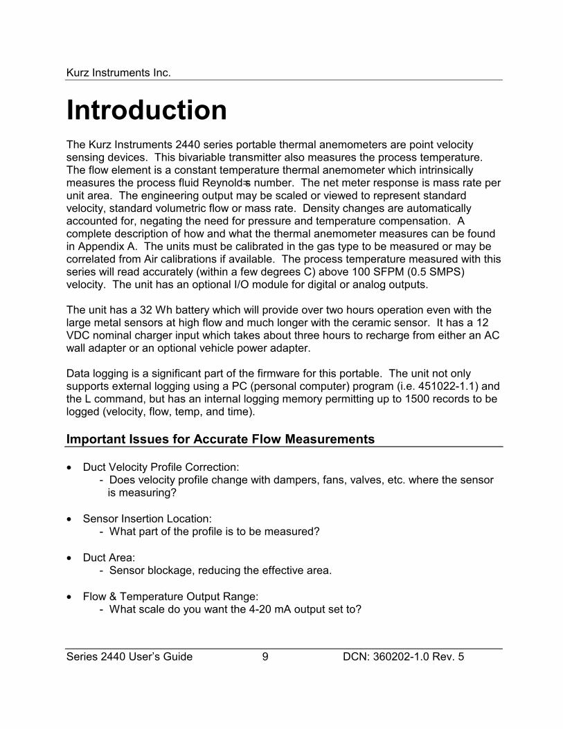
IntroductionThe Kurz Instruments 2440 series portable thermal anemometers are point velocitysensing devices. This bivariable transmitter also measures the process temperature. The flow element is a constant temperature thermal anemometer which intrinsicallymeasures the process fluid Reynold=s number. The net meter response is mass rate perunit area. The engineering output may be scaled or viewed to represent standardvelocity, standard volumetric flow or mass rate. Density changes are automaticallyaccounted for, negating the need for pressure and temperature compensation. Acomplete description of how and what the thermal anemometer measures can be foundin Appendix A. The units must be calibrated in the gas type to be measured or may becorrelated from Air calibrations if available. The process temperature measured with thisseries will read accurately (within a few degrees C) above 100 SFPM (0.5 SMPS)velocity. The unit has an optional I/O module for digital or analog outputs.
The unit has a 32 Wh battery which will provide over two hours operation even with thelarge metal sensors at high flow and much longer with the ceramic sensor. It has a 12VDC nominal charger input which takes about three hours to recharge from either an ACwall adapter or an optional vehicle power adapter.
Data logging is a significant part of the firmware for this portable. The unit not onlysupports external logging using a PC (personal computer) program (i.e. 451022-1.1) andthe L command, but has an internal logging memory permitting up to 1500 records to belogged (velocity, flow, temp, and time).
Important Issues for Accurate Flow Measurements
• Duct Velocity Profile Correction:- Does velocity profile change with dampers, fans, valves, etc. where the sensor
is measuring?
• Sensor Insertion Location:- What part of the profile is to be measured?
• Duct Area:- Sensor blockage, reducing the effective area.
• Flow & Temperature Output Range:- What scale do you want the 4-20 mA output set to?

Kurz Instruments Inc.
Series 2440 User’s Guide 10 DCN: 360202-1.0 Rev. 5
• Field Calibration:- From a field calibration, either velocity dependent correction factors or a simple
gain correction can be entered to account for the duct flow profile.
• Sensor Pitch or Orientation to the Flow:- Is the flow arrow pointing in the same direction as the flow?
• Medium to be Measured:- Was the unit calibrated in the medium to be measured?- Is the medium composition highly variable?- Does the medium change phase?- Can material build up on the sensor?- Are there large temperature variations?
• Kickout Values for the NE-43 Alarms (< 3.6 mA and > 21 mA)?- What high/low values indicate a meter malfunction or a high/low flow trip point.?- What high/low values indicate normal operating conditions?
Answers to many of these questions can be found in this manual or its appendices. Kurzcustomer service may also be contacted for assistance (831-646-5911 or FAX 831-646-1033, [email protected] ). This summary guide covers setup,configuration, operation, calibration and troubleshooting. Many of the terms andabbreviations used in this manual may be found in the Glossary.
The intended audience for this manual is process engineers and instrumentationtechnicians who are measuring gas flow, HVAC applications etc. The Appendix of thismanual has the menu state diagram, signal flow diagram, field wiring diagram, in-situvelocity traverses, Modbus commands and a tutorial guide on what a thermalanemometer measures.
The 2440 is designed as a non-incendive device which means it may be used in Class I,Division 1 areas or Zone 2. As such, it should not be used for flammable gasmeasurements which require a higher level of safety design like explosion proof orintrinsically safe. The 2440 safety approval is not available yet. The unit is being soldfor non-hazardous gas measurements only, even though it will work on any gas and canbe calibrated for any gas.
Kurz Instruments Inc.
Series 2440 User’s Guide 11 DCN: 360202-1.0 Rev. 5
Basic OperationThe 2440 is a straight forward unit with intuitive user interface. You just plug in thesensor and press the power button and back light if it improves the LCD viewing. Notethat each 2440 has a serialized sensor that must be matched to its electronics. You cannot interchange sensors with 2440 display units and preserve the rated accuracy. Theunit takes about eight seconds to boot up and will initially display an LCD display driverscreen which is cleared and is followed by the firmware level (PTA VER 1.0x) andExecutive State scroll. The Executive State will scroll through its 3 available METERs,time/date and help prompt: The three METERs represent the following:
METER 1 VelocityThis is a point velocity measurement at the sensor. This is the primary useof this portable. The unit has a low velocity cutout, which forces thereading to zero when below the user selected value. The factory default is0 SFPM (0 SMPS).
METER 2 Flow RateThis is based on the idea of an average velocity measurement multipliedby area. You may also add correction factors to account for changingvelocity profiles. This meter also has a low flow cutout preset to 0.
METER 3 TemperatureThis is the ambient temperature at the sensor. This measurement is validwith process gas flowing across the sensor. At zero or low velocities, it willread too high due to interference from the heated velocity element, assuch, there is a user programmable low-velocity cutout for the temperature. At zero flow you will see TEMPERATURE NOT VALID on the screenunder these low velocity conditions. The factory default is 100 SFPM (0.5SMPS)
The reading of any parameters shown in the Executive State scroll may be held bypressing the H or hold key. When done viewing in hold mode, you may clear this bypressing the C or the clear key.
If you access the keypad and press the D function key, this will permit viewing of theMETER data for velocity, flow or temperature. Pressing the P function key accesses theProgramming mode. The user code is A123456" followed by the E key to accept thiscode. If either mode is selected and there is no keypad action within two minutes, it willrevert to the Executive State. It is important to know that while in Program mode, the
Kurz Instruments Inc.
Series 2440 User’s Guide 12 DCN: 360202-1.0 Rev. 5
outputs (4-20 mA) will not update and will remain frozen at their values when you firstentered the Program mode.
All of the above menus may be accessed via the RS-232 or RS-485 ports using aterminal emulator program. You can set the baud rate between 1200 and 38.4 k. Themenus/screens will role up on the terminal screen as time passes. The function keys interminal mode are the same as the 4x5 keypad but in lower case. There is also acommand which will turn off the display or echo of the display characters to the serialports. This is accomplished by pressing the A+@ key, (shift +). Pressing this again willtoggle it back on. The unit still responds to the keyboard commands q, l, ?, + andescxxx when the echo is off. The up arrow ^ (shift 6, above the 6 key) is the same asYES and will move you from one screen to another. Alternately you can use the downarrow v (small v) or NO to move from one screen to another in the opposite direction. Asummary of these single key commands can be found by pressing “?” from the terminalkeyboard.
Navigating the Menus
Pressing P or D will advance the menu categories forward in that mode one screen at atime without changing anything. If you continue pressing the keys, you will end up backwhere you started. If you overshoot the menu category of interest, you can backup (vkey). Alternately, you can also move forward with the (^ key). Once you enter a menucategory within Program or Display mode you can only advance the screens with the Dor P key depending on the mode you=re in. The ^v keys within the menu categories areused to change entries or selections.
Selecting Menus
You select a menu category of interest by pressing the E key or Enter on the remoteterminal. Sometimes you have the option of choosing more than one meter, or outputbefore entering a menu. At these screens the ^v keys will change the specific menuyou first enter. Some menus accept direct number input from the keypad or terminal. To deselect or get out of a menu you press the C key once or twice depending on themenu.
Entering Data
Kurz Instruments Inc.
Series 2440 User’s Guide 13 DCN: 360202-1.0 Rev. 5
You enter data into a menu by typing the number directly from the keypad, includingdecimal points. The ^v arrow keys will also change values. When you first enter amenu, the most significant digit is changed by the ^v keys. If you press a number itautomatically is entered starting at the most significant digit then it moves the entry pointto the right one character. At any time you may change the last entered value with the ^v keys.
For menus with multiple selections, the ^v keys are needed to change the selection.
Once you have entered the number or selected the parameter of interest, the value isaccepted by pressing the E or enter key.
Note: When entering meter IDs or other text using a remote terminal, you must useupper case characters only. The lower case are used for the keyboard commands.
Clearing Data, Editing Data or Exiting Menus
The D or delete key will clear one character to the left just like a backspace key on acomputer. The C key will clear the whole value in a menu. Pressing the C key asecond time will exit the menu without any change.
Holding a Menu For Display
You may freeze or hold any menu beyond the two minute auto-return interval to view theinformation like flow rate or temperature by simply pressing the H key. This mode isremoved by pressing the C key.
Help Display
A list of local commands can be found by pressing the H key twice or HH. The helpscreens list the firmware revision level, Sensor S/N, Kurz telephone and FAX numbers,website address and menu instructions.
Flow Meter Time Constant
Kurz Instruments Inc.
Series 2440 User’s Guide 14 DCN: 360202-1.0 Rev. 5
There are four different factors controlling the speed of the meter.
$ Sensor Response Time (see Brochure)$ ADC Sample Rate (see programming section for adjustments)$ 4-20 mA Output update rate (see Brochure)$ METER Filter time constant (see programming section for adjustments)
Depending on the various settings, you can have a response time which is sensorlimited or over damped using the METER Filter. The net response is the cascade of allthe above. So even if the METER Filter time constant is at 0 seconds, the sensor willstill limit the response time.
Data Logging
The 2440 is designed for both internal logging with its test-set memory, trend memoryand events or externally via its serial port to a PC. The following section describes theexternal logging and is described in the chapter on Program mode.
External Data Logging
The optional log command is the L key from the local keypad. You get a summary ofthe meter, ID, rate and totalization. From a remote terminal this can be initialized usingthe Al@ key, lower case L. This output from the L command is fairly fast and can be usedinstead of the 4 to 20 mA output if you do some text parsing.
Kurz Instruments, Inc. has an optional Windows PC program (# 451022) which will pollthe 2440 using the L command and write the data to a file on the computer. Theprogram will also average the data after it has been captured to reduce the file size. Averaging can be on a fixed number of records or a fixed elapsed time. The format ofthis file can be read directly into a spread sheet program (space delimited data with allMETERs on one line or record).
This external log can be set to start on its own by setting a log interval starting at oneminute up to 999 hours. The format is hhh:mm on the display and you first enter thehours in a menu screen followed by the minutes (up to 59) menu screen under Programmode.
Example data from the 2440 log function or the L command:
Host issues l (lower case L) Reply: TIME: 13:58:34 9/18/2000
Kurz Instruments Inc.
Series 2440 User’s Guide 15 DCN: 360202-1.0 Rev. 5
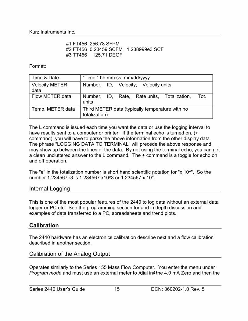
#1 FT456 256.78 SFPM #2 FT456 0.23459 SCFM 1.238999e3 SCF #3 TT456 125.71 DEGF
Format:
Time & Date: "Time:" hh:mm:ss mm/dd/yyyyVelocity METERdata
Number, ID, Velocity, Velocity units
Flow METER data: Number, ID, Rate, Rate units, Totalization, Tot.units
Temp. METER data Third METER data (typically temperature with nototalization)
The L command is issued each time you want the data or use the logging interval tohave results sent to a computer or printer. If the terminal echo is turned on, (+command), you will have to parse the above information from the other display data. The phrase "LOGGING DATA TO TERMINAL" will precede the above response andmay show up between the lines of the data. By not using the terminal echo, you can geta clean uncluttered answer to the L command. The + command is a toggle for echo onand off operation.
The "e" in the totalization number is short hand scientific notation for "x 10^". So thenumber 1.234567e3 is 1.234567 x10^3 or 1.234567 x 10³.
Internal Logging
This is one of the most popular features of the 2440 to log data without an external datalogger or PC etc. See the programming section for and in depth discussion andexamples of data transferred to a PC, spreadsheets and trend plots.
Calibration
The 2440 hardware has an electronics calibration describe next and a flow calibrationdescribed in another section.
Calibration of the Analog Output
Operates similarly to the Series 155 Mass Flow Computer. You enter the menu underProgram mode and must use an external meter to Adial in@ the 4.0 mA Zero and then the
Kurz Instruments Inc.
Series 2440 User’s Guide 16 DCN: 360202-1.0 Rev. 5
20.0 mA Span. The ^v keys are used to raise or lower the output until it matches thetwo conditions listed. Once they are in agreement, you press the E key to accept thisvalue. The programming section has a long version of this calibration procedure.
Calibration of the Analog Input
There is no user calibration of the inputs. This is a Factory process only. If yourtransmitter is reading the ambient temperature within a few degrees when the flow rateis higher than 100 SFPM (0.5 SMPS), then the input is properly calibrated and yoursensor is most likely working too.
External Communications To The Portable
The field wring diagram for the 2440 is drawing 342035 found in the Appendix. Besidesshowing the charger and sensor connections, examples of how the optional I/O adapteris used are provided. The adapter has the following external data connections:
• RS-232 with DB-9 connector for a straight cable connection to a typical PC• RS-485 with screw terminal clamp wire connections for a network using the option
Modbus protocol.• 4-20 mA outputs 1 and 2 which can be flow, velocity, temperature or even two ranges
of the same variable.
The serial port can be RS-232 or RS-485 but not both at the same time. The jumper onthe I/O board selects which serial data standard is used. The baud rate and protocol arespecified in Program mode. Typically the RS-232 port is used to transfer data stored inthe internal trend or test (also known as test-set) memory to a PC for permanentstorage, further manipulations and graphing with a spread sheet program (seesubsequent examples).
The analog outputs are loop powered and isolated. They are factory calibrated but maybe field set in Program mode. These outputs would typically be connected to a datarecorder or chart recorder. Several examples on how to wire up these ports areprovided in the field wring diagram, 342035 found in the Appendix.
Modbus Industrial Network Protocol
The Modbus mode of communications is used with the RS-232 (point to point) or RS-485 (point to point or multipoint). The 2440 supports both the ASCII and RTU versions

Kurz Instruments Inc.
Series 2440 User’s Guide 17 DCN: 360202-1.0 Rev. 5
of Modbus. When configured in this mode, it will not operate as a Remote Terminal orperform Data logs or its Upload/Download functions.
The RS-485 can be configured as Full Duplex (4 wire + GND) or Half Duplex (2 wire +GND). Modbus is a network communication protocol that was developed by Modicon fortheir controllers. The controllers can communicate using a master-slave technique inwhich only one device, the master, can initiate transactions , called queries. The otherdevices, slaves, respond by supplying the requested data to the master or by taking theaction requested in the query. The master can address individual slaves, and the slavewill respond by returning a message or response to the query that is individuallyaddressed to it. The Modbus protocol establishes the format for the master’s query bycombining the device address, a function code defining the requested action, any datato be sent, and an error checking field for the data packet. The slave’s responsemessage is also constructed using Modbus protocol. It contains a field confirming theaction taken, any data to be returned, and an error checking field. If an error occurred inreceipt of the message or the slave is unable to perform the requested action, the slavewill construct an error message and send it as the response. You can find more detailson the protocol at the Modicon website www.modicon.com where and on line version ofthe PI-MBUS-300 standard is available.
Battery Discharge, Charge and AC powered
The battery discharge or operational time of the 2440 will depend on the sensor load(sensor type, flow rate and process temperature). Switch mode power supplies are usethroughout the 2440 to make efficient use of the battery energy. With the metal cladsensors (2443, 44, 45) you will have over two hours operation on a charge. The ceramicsensors (2441, 42) will work almost four hours on a charge. The 2444 is shown on thefront cover of this manual.
As a battery powered portable device, the 2440 must be charged to work properly. Typical fast charge from a dead battery will occur in three hours. The fast charge willrefill the battery to about 90% charge with the trickle charge doing the rest. If the unit istoo cold (below 0 °C) or hot (battery > 50 °C) it will not start the fast charge. The LEDnear the 12 VDC charger input indicates fast charge. If 12 V is applied to the chargerinput and it is not in fast charge, then the battery is being trickle charged. This is lowenough in current as to do no harm to the battery even when left on past the fast chargetime indefinitely.
The 2440 has an automatic shutdown when the battery has been discharged below 0%charge to protect the battery and will not restart until partly charged or enough time haspassed for the battery to partly recover.

Kurz Instruments Inc.
Series 2440 User’s Guide 18 DCN: 360202-1.0 Rev. 5
The AC powered charge adapter has a universal input accepting 100 to 240 VAC, 50/60Hz. The 12 V charge adapter has a standard IEC 2-pin plug that will accept any localpower plug. See the 342035 wiring diagram for the cord part number in your area.
The unit will operate when charging, but since some of the charge current is beingdiverted to operate the unit, the battery may not reach a full charge before the chargercontrol circuit times-out (3 hours). Once the charger times-out or thinks the battery isfully charged, it switches to trickle charge mode. If the unit is left on, it will eventuallydischarge the battery then shutdown, even though the charger is plugged in. The tricklecharge is not enough to overcome the 2440 load even at low flow. Whenever the 12VDC power is cycled, the charger will reset and attempt a fast charge on the battery.
If you want a full battery charge during one charge cycle, you must keep the unit offwhile charging. Due to the temperature limits on battery charging (0 to 50° C), to ensurea full charge, allow the unit to reach room temperature before starting a charge.
Multiple batteries may be used with the 2440 but they must be charged in the main unitas described above then unplugged for external storage. As the unit charges quicklyand will operate when the charger is plugged in, the need for multiple batteries is notcommon.
Externally Powered
To operate the portable continuously, the charger (AC or Vehicle) will provide the powerbut it must be fooled into staying on. The internal 2440 charger will stay on in standbymode (the state it goes into after a power cycle on the 12 V input) by removing(unplugging) the battery. Without the battery present, the charge circuit will operate the2440 continuously with any sensor at any flow rate.
The battery cover is held on with four #2 cross point head screws. The battery is furtherheld in place with foam to keep it from rattling in its case. It is important to note thepolarity on the battery connector when removing. Plugging in with the pins off by onemay damage the unit. The wrong polarity (whole thing backward) will not damage theunit, but it will not turn on from the battery.
Charge Status
The temporary menu screen:
WARNING!!!
Kurz Instruments Inc.
Series 2440 User’s Guide 19 DCN: 360202-1.0 Rev. 5
BATTERY IS LOWwill come on for a few seconds every few minutes below 20 % charge. The unit willcontinue to work below 0 % charge but not for long. The automatic shutoff willeventually trip to protect the battery from excessive discharge. You may view the batterystatus anytime under Display mode following the temperature meter.
BATTERY CHARGE:100 PERCENT
As with most portable devices, the percent charge is approximate based on the batteryvoltage. Since this is not temperature corrected, there will be some error when thebattery is below or above room temperature. The charge status is based on a 20° Cvoltage discharge curve. When the battery is cold, its voltage is lower so the indicatorunder estimates the charge and above room temperature, the voltage is higher so thecharge status over estimates the true charge.
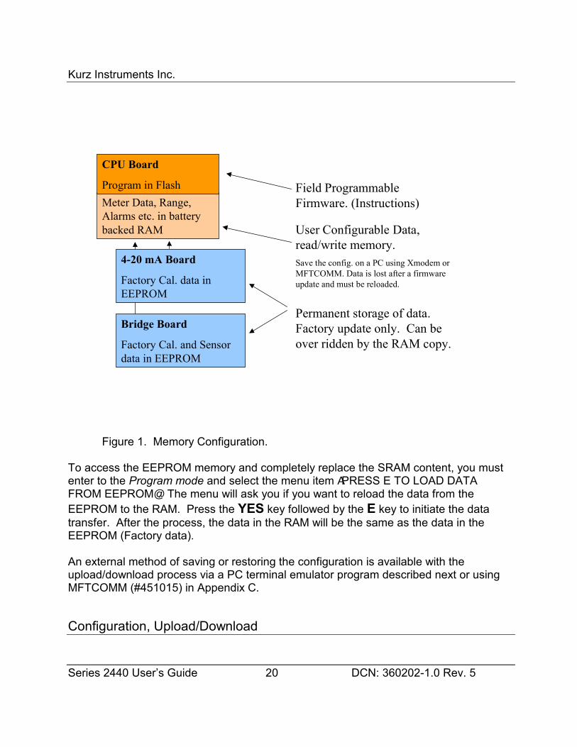
Configuration Data Storage
The configuration data is stored two ways in the 2440 (See figure 1). The primarymethod is a battery backed up CMOS RAM or SRAM. All information about the flowmeter is stored in this memory. In addition, the original Factory configuration is stored inthe EEPROMs located on the analog input and output boards of the unit. These can beused in the event of corruption of the RAM. Meter settings, IDs, Area, Alarms etc are notstored in EEPROM, only SRAM.
Kurz Instruments Inc.
Series 2440 User’s Guide 20 DCN: 360202-1.0 Rev. 5
Figure 1. Memory Configuration.
To access the EEPROM memory and completely replace the SRAM content, you mustenter to the Program mode and select the menu item APRESS E TO LOAD DATAFROM EEPROM@. The menu will ask you if you want to reload the data from theEEPROM to the RAM. Press the YES key followed by the E key to initiate the datatransfer. After the process, the data in the RAM will be the same as the data in theEEPROM (Factory data).
An external method of saving or restoring the configuration is available with theupload/download process via a PC terminal emulator program described next or usingMFTCOMM (#451015) in Appendix C.
Configuration, Upload/Download
Bridge Board
Factory Cal. and Sensordata in EEPROM
4-20 mA Board
Factory Cal. data inEEPROM
Meter Data, Range,Alarms etc. in batterybacked RAM User Configurable Data,
read/write memory.Save the config. on a PC using Xmodem orMFTCOMM. Data is lost after a firmwareupdate and must be reloaded.
Permanent storage of data.Factory update only. Can beover ridden by the RAM copy.
CPU Board
Program in Flash Field ProgrammableFirmware. (Instructions)
Kurz Instruments Inc.
Series 2440 User’s Guide 21 DCN: 360202-1.0 Rev. 5
The upload/download process allows you to save not only the Factory data but your fieldcustomization in a remote file on a PC.
The easiest way to do this is to install and use MFTCOMM (#451015) version 1.4x orhigher described in Appendix C. This is a Windows program (NT/Win98/95) provided ona 3 2" floppy disk containing the Factory configuration of your unit. This program willalso allow you to make a printable hardcopy of the setup.
If you do not have MFTCOMM or do not want to use it, you can us a terminal emulatorprogram with Xmodem. This will transfer a binary file of about 2.2 kbytes in five secondsat 9600 baud. To initiate this you enter the command:
EscuploadRet
That is the Aesc@ or escape key on your keyboard followed by the text Aupload@ then theenter key or return key. You will be prompted that it is ready to start the Xmodemreceive on the PC. If you spend too much time (more than 60 seconds) getting started,you will have to issue the command again.
To copy this configuration back into the unit, use the command:
EscdownloadRet
That is the Aesc@ or escape key on your keyboard followed by the text Adownload@ thenthe enter key or return key. You will be prompted that it is ready to start the Xmodemtransmit file on the PC. Again you have 60 seconds before it times out.
The above commands are effective only when the Series 2440 is in the Executive Mode.It is recommended to turn OFF the terminal echo during this process to avoid dumpingcharacter strings on the terminal screen. Refer to the section Overview of the userInterface on how to turn the terminal echo ON and OFF.
THE NEW 2440 SERIESPORTABLE AIR MEASUREMENT INSTRUMENTS WITH "SMARTS"
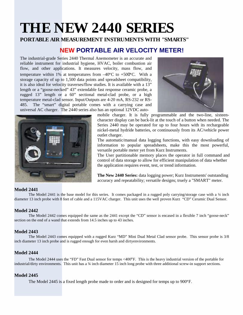
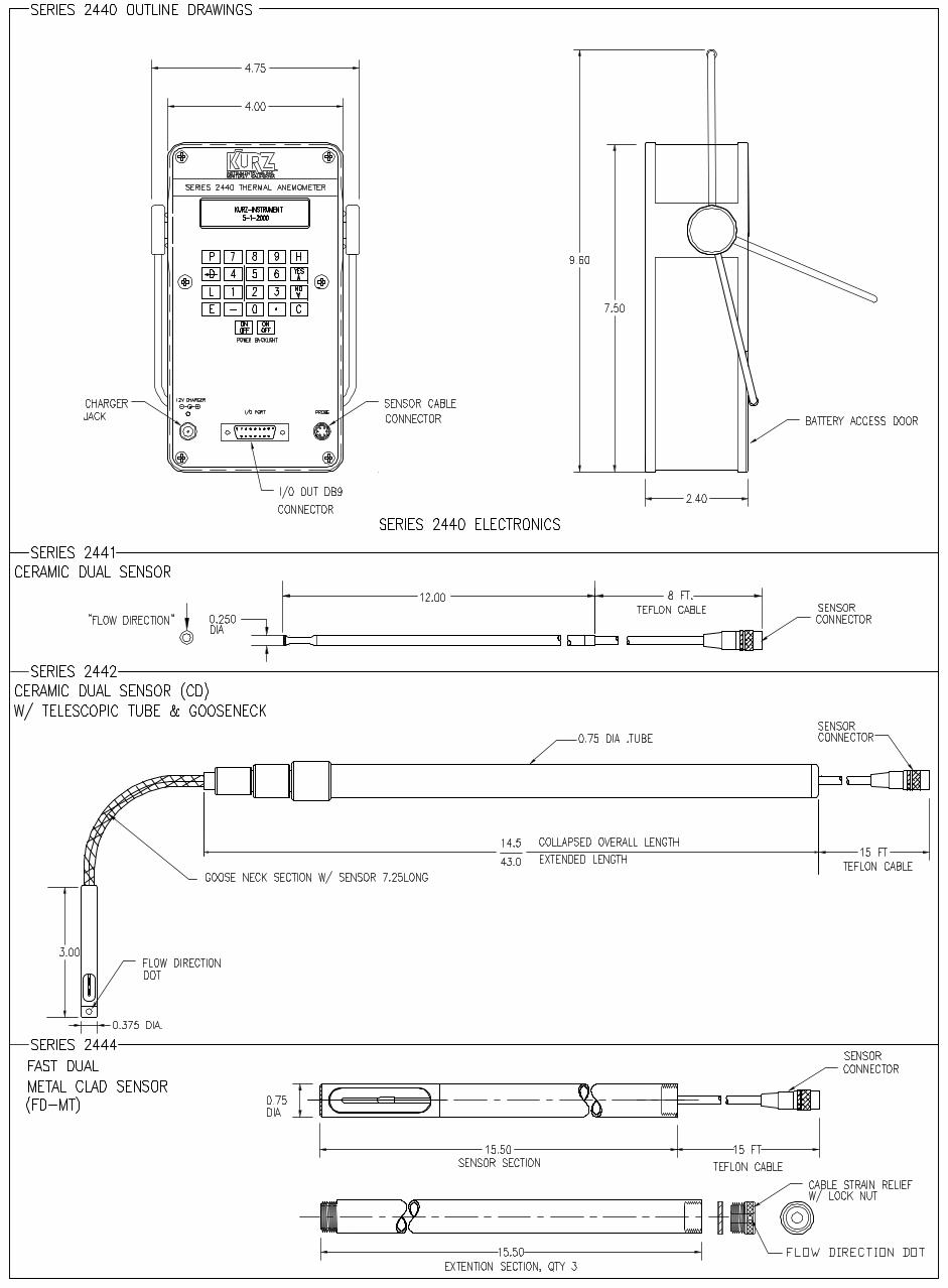
NEW PORTABLE AIR VELOCITY METER!The industrial-grade Series 2440 Thermal Anemometer is an accurate andreliable instrument for industrial hygiene, HVAC, boiler combustion airflow, and other applications. It measures velocity, mass flow, andtemperature within 1% at temperatures from –40ºC to +500ºC. With astorage capacity of up to 1,500 data points and spreadsheet compatibility,it is also ideal for velocity traverses/flow studies. It is available with a 13”length or a “goose-necked” 43” extendable fast response ceramic probe, arugged 13” length or a 60” sectional metal-clad probe, or a hightemperature metal-clad sensor. Input/Outputs are 4-20 mA, RS-232 or RS-485. The “smart” digital portable comes with a carrying case anduniversal AC charger. The 2440 series also has an optional 12VDC auto-
mobile charger. It is fully programmable and the two-line, sixteen-character display can be back-lit at the touch of a button when needed. TheSeries 2440 may be operated for up to four hours with its rechargeablenickel-metal hydride batteries, or continuously from its AC/vehicle poweroutlet charger.The automatic/manual data logging functions, with easy downloading ofinformation to popular spreadsheets, make this the most powerful,versatile portable meter yet from Kurz Instruments.The User partitionable memory places the operator in full command and control of data storage to allow for efficient manipulation of data whether the application requires event, test, or trend information.
The New 2440 Series: data logging power; Kurz Instruments' outstanding accuracy and repeatability; versatile designs; truely a "SMART" meter.
Model 2441The Model 2441 is the base model for this series. It comes packaged in a rugged poly carrying/storage case with a ¼ inch
diameter 13 inch probe with 8 feet of cable and a 115VAC charger. This unit uses the well proven Kurz “CD” Ceramic Dual Sensor.
Model 2442The Model 2442 comes equipped the same as the 2441 except the “CD” sensor is encased in a flexible 7 inch “goose-neck”
section on the end of a wand that extends from 14.5 inches up to 43 inches.
Model 2443The Model 2443 comes equipped with a rugged Kurz “MD” Mini Dual Metal Clad sensor probe. This sensor probe is 3/8
inch diameter 13 inch probe and is rugged enough for even harsh and dirtyenvironments.
Model 2444The Model 2444 uses the “FD” Fast Dual sensor for temps <400ºF. This is the heavy industrial version of the portable for
industrial/dirty environments. This unit has a ¾ inch diameter 15 inch long probe with three additional screw-in support sections.
Model 2445The Model 2445 is a fixed length probe made to order and is designed for temps up to 900 ºF.
OUR MISSION
To manufacture and market
the best thermal mass flow meters
available and to support our
customers in their efforts to
improve their business.
▲▲
▲▲
▲▲
▲▲
▲▲
▲▲
▲▲
▲▲
▲▲
▲▲
▲▲
▲▲
DESCRIPTION
Series 2440 Portable Mass Flow
Meters raise the standard for
measurement of air and
industrial gasses.
The industrial-grade 2440
Series Thermal Anemometer
is an accurate and reliable
instrument for HVAC, boiler
combustion air flow, industrial
hygene, and other applications.
It measures velocity, mass flow,
and temperature within 1% at
temperatures from -40 to +500
degrees C. With a storage
icapacity of over 1,500 data
points and spreadsheet compati-
bility, it is also ideal for velocity
traverses/flow studies. It is
available with a 13" length or a
"goose-necked" 43" extendable
fast response ceramic probe, a
srugged 13" length or a 60"
sectional metal-clad probe, or a
high temperature metal-clad
sensor. Input/Outputs are 4-20
mA, RS-232 or RS-485. The
"smart" digital portable comes
with a carrying case and a
universal AC charger. It is fully
programmable and the two-line
sixteen-character display can be
backlt at the touch of a button.
The automatic/manual data
logging functions, with easy
downloading of information
to popular spreadsheets, make
this the most powerful, versatile
portable meter yet from Kurz
Instruments.
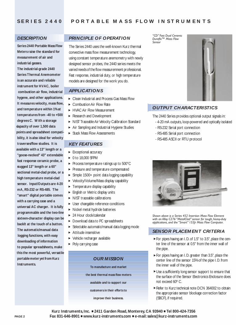
“CD” Fast Dual CeramicDuraflo™ Mass FlowSensor
S E R I E S 2 4 4 0 P O R T A B L E M A S S F L O W I N S T R U M E N T S
OUTPUT CHARACTERISTICS
The 2440 Series provides optional output signals in: - 4-20 mA outputs, loop-powered and optically isolated - RS-232 Serial port connection - RS-485 Serial port connection - RS-485 ASCII or RTU protocol
PRINCIPLE OF OPERATION
The Series 2440 uses the well-known Kurz thermal convective mass flow measurement technology,using constant temperature anemometry with newlydesigned sensor probes, the 2440 series meets the varied needs of the flow measuremnent professional.Fast response, industrial duty, or high temperaturemodels are designed for the work you do.
APPLICATIONS
Clean Industrial and Process Gas Mass FlowCombustion Air Flow RateHVAC Air Flow MeasurementResearch and DevelopmentNIST Traceable Air Velocity Calibration StandardAir Sampling and Industrial Hygiene StudiesStack Mass Flow Assessments
KEY FEATURES
Exceptional accuracy 0 to 18,000 SFPMProcess temperature ratings up to 500°CPressure and temperature compensatedSimple 1500+ point data logging capabilityVelocity/Volume/Mass display capabilityTemperature display capabilityEnglish or Metric display unitsNIST traceable calibrationsUser changable reference conditionsNickel metal hydride batteries24 Hour clock/calendarDownload data to PC spreadsheetsSelectable automatic/manual data logging modeAttitude insensitiveVehicle recharger availablePoly carrying case
Shown above is a Series 452 Insertion Mass Flow Element with an Alloy C276 “MetalClad” sensor for tough, heavy-dutyapplications, and the “Smart” 155Jr Mass Flow Computer.
SENSOR PLACEMENT CRITERIA
For pipes having an I. D. of 1.5" to 3.5", place the cen-ter line of the sensor at 0.5" from the inner wall of the pipe.
For pipes having an I. D. greater than 3.5", place the center line of the sensor 15% of the pipe I. D. from the inner wall of the pipe.
Use a sufficiently long sensor support to ensure that the surface of the Sensor Electronics Enclosure does not exceed 60º C.
Refer to Kurz technical note DCN 364002 to obtain the appropriate sensor blockage correction factor (SBCF), if required.
▲
▲
▲
▲
PAGE 2
Kurz Instruments, Inc. ■ 2411 Garden Road, Monterey, CA 93940 ■ Tel 800-424-7356Fax 831-646-8901 ■ www.kurz-instruments.com ■ e-mail: [email protected]
SERIES 2440 MODEL OUTLINESSPECIFICATIONS
Process Velocity Range:0-18,000 SFPM
Process Temperature Rating:MT: -40°C to 500°C
Sensor Material:Kurz proven "CD", "MD", and"LD" ceramic and metal-clad
Sensor Support Material:316L Stainless SteelAlloy C276
Repeatability: 0.25%Response Time (One TC):
Velocity: model dependent 50ms - 1 secTemperature: 300ms - 3 sec
Power: NiMH rechargable
S E R I E S 2 4 4 0 P O R T A B L E M A S S F L O W I N S T R U M E N T S
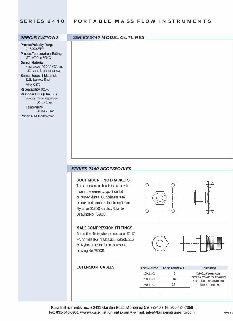
DUCT MOUNTING BRACKETSThese convenient brackets are used tomount the sensor support on flat or curved ducts. 316 Stainless Steelbracket and compression fitting,Teflon,Nylon or 316 SS ferrules. Refer toDrawing No. 759030.
MALE COMPRESSION FITTINGSBored-thru fittings for process use, 1⁄4", 3⁄8",1⁄2", 3⁄4" male IPS threads, 316 SS body, 316SS, Nylon or Teflon ferrules. Refer todrawing No. 759031.
EXTENSION CABLES
SERIES 2440 ACCESSORIES
Part Number Cable Length (FT) Description
260111-01 8 "Quick-Couple" extension cables
260111-02 16 made to provide the flexability
260111-03your unique process control
24 situation requires.
PAGE 3
Kurz Instruments, Inc. ■ 2411 Garden Road, Monterey, CA 93940 ■ Tel 800-424-7356Fax 831-646-8901 ■ www.kurz-instruments.com ■ e-mail: [email protected]
Kurz Instruments Inc.
Series 2440 User’s Guide 23 DCN: 360202-1.0 Rev. 5
Program ModeAfter reading over the basic navigation information in the operation and Menu-Statediagram in the Appendix, you can setup or configure anything you need for your Series2440 unit. This section explains what the various parameters are for. Not all functionslisted may be available with your unit depending on what was ordered.
Functions Available in Program Mode
All the programming menus and controls are shown on the Menu State Diagram(342034) in the Appendix E and navigation of this was described previously. This is anoutline of what you can do in Program mode.
System Configuration:Some of the available features of the 2440 are Factory set parameters thatdepend on what was ordered. This includes the communications options and thenumber of analog outputs, enable of the fast ADC rate of 250 Hz,communications modes and external data logging.
Set System UnitsYou can change the displayed data in either English or metric units. Thisselection is works no mater what units or reference conditions were used for theoriginal calibration data.
Reset TotalizerThe flow or mass totalization and elapsed time is maintained by a set of internalvariables, which are battery backed up. This variable has about seven digits ofresolution but will totalize for about four years with better than 1% tracking. Thismenu will reset the flow and elapsed time variables to zero.
Set Time and DateThere is a year 2000 compliant real time clock and calendar, which annotates thedisplay and logged output. This clock has one-second resolution on the internaland external logged data.
Set ADC Sample RateThe Analog to Digital Converter (ADC) which reads the sensor signal has 16 bitresolution when operating at 50 or 60 Hz data rate. It can reject any power linefrequency noise easily when the converter rate matches the power line. This is
Kurz Instruments Inc.
Series 2440 User’s Guide 24 DCN: 360202-1.0 Rev. 5
generally not an issue unless you have very long wires in a very noisy area
Flow Calibration DataThis menu displays the sensor serial number, Factory calibration referenceconditions and permits the user to label the gas name and change the referencetemperature, pressure and gas molecular weight. The molecular weight is onlyused when computing mass rate.
METER 1 Velocity ParametersThis menu is use to select the METER ID or tag, choice of insertion or in-line flowand the velocity dependent correction factors. You can program the velocity orflow rate for the high and low Kick-Out points. The low velocity cut-off value isalso programmable. This is useful to prevent zero flow or low flow drift due totemperature and pressure changes.
METER 2 Flow Rate ParametersThese parameters are similar to METER 1 with the addition of a flow area, sensortype and depth for computing a Sensor Blockage Correction Factor (SBCF). TheSBCF is a multiplier to the flow calculation to reduce the effective area by theprobe projection on to the duct cross sectional area.
METER 3 Temperature ParametersThe temperature METER also has an ID or tag, correction factors and a high andlow Kick-Out value. More importantly, the low velocity cut-out is programmedhere. Since the ambient temperature is measured with the velocity probe, it willread high a low velocity due to self-heating. To mask this error, it will report“TEMP NOT AVAILABLE” below this set point velocity. It is recommend to keepthis at 100 SFPM (0.5 SMPS). The way the unit is designed, if it does not readthe ambient temperature with-in a few degrees C of the true temperature with gasflowing across it, then the unit is defective and should be returned for service.
Set METER Filter TCEach of the three METERs can have a time constant (tau, τ) to reduce its noise. This Time Constant (TC) is like that which applies to an electrical circuit with aresistor (R) and capacitor (C) making a low pass filter, τ = RC. With a stepchange on the input, after one time constant the output change will reach 63% ofits final value. The settling time is about five time constants to reach the finaloutput within 1%.
Calibration of the 4-20 mA outputsThe analog output must have its circuits adjusted so when the flow computercommands zero for and output that you actually get 4.00 mA and similarly when
Kurz Instruments Inc.
Series 2440 User’s Guide 25 DCN: 360202-1.0 Rev. 5
you request span that you get 20.00 mA.
Set Analog OutputsThe assignment of which analog output is matched to which METER is made inthis menu area. There are only two analog outputs which are typically set to thevelocity and temperature METERs. You can range the flow, velocity, temperatureor mass rate to the Low and High values of the 4-20 mA signals. A METER kick-out low will cause the output to go below 3.6 mA and a kick out high will cause itto go above 21 mA. This is the NE-43 specification.
Set AlarmsAny of the METERs can have Solid State Relay (SSR) alarm contact associatedwith it. There are two SSRs in this unit which are rated for 0.8 A, 24 V AC/DC. You can alarm on just about any condition from the METER’s output. Onceassigned, the alarm can be turned On/Off, Normally Open or Closed, HI, Low,HI/Low based on a set point. These alarms are self clearing when the conditionchanges not requiring a reset.
Load Calibration Data from EEPROMThe Factory calibration data for the ADC, Sensor, 4-20 mA board etc are storedin a non-volatile memory known as an EEPROM. This data is loaded into theSRAM of the unit when new, but may be partly modified by the user. If the SRAMbecomes corrupted or you wish to force a loading of the data from the EEPROMyou can using this menu. There is one EEPROM on the bridge board which hasall the sensor data and one on the 4-20 mA board which has its calibration.
Meter IDs or Tags, flow units, ranges, correction factors etc. are not part of thecalibration data stored in these EEPROMs.
Set Communications ModeThe 2440 supports the classic remote terminal mode designed for humans toread and control as well as Modbus which is designed for computers or PLCs(Programmable Logic Controllers) to communicate with it. With the Modbusprotocol, you can have many devices sharing the same set of wires, each with itsown address (1 to 246) which is set in the menu. Once you select the Modbusprotocol, it will stop its terminal mode echo and you can only change it back usingthe local keypad/display. Both the RTU and ASCII versions of Modbus aresupported. In full duplex, you can operate at any Baud rate. In half duplex RS-485, you must be at 9600 or higher for the Modbus to work reliably.
Kurz Instruments Inc.
Series 2440 User’s Guide 26 DCN: 360202-1.0 Rev. 5
Set Baud RateThe baud rate for serial communications with RS-232/RS-485 in terminal orModbus mode is set in this menu. The default value is 9600 but it may be set at1200, 2400, 4800, 9600, 14.4 k, 19.2 k and 38.4 k.
Set Data LoggingThis menu is for external data logging. Here you configure an internal timer toissue the equivalent of the L command which summarizes each METER. Thiscan be set as hhh:mm format for hours and minutes. You may also turn thisfunction off.
Set Memory Data LoggingThis menu is for internal data logging to the battery backed up memory. You canspecify what percentage of the 1500 data records will be trend data and thebalance will be test-set data records.
Access Memory Log.To record test-set data, view test-set data locally or transfer a file of trend, test-setor event data, you enter this menu.
Executive Mode ScrollAfter booting up or turning on, the screen of the 2440 will scroll through thetime/date, help prompt screen, velocity METER, flow rate METER, temperatureMETER then start over.
Entering Program Mode
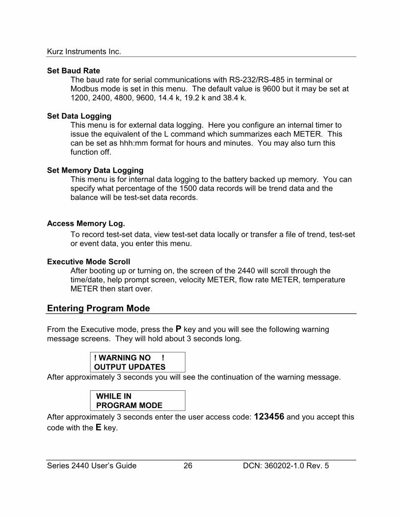
From the Executive mode, press the P key and you will see the following warningmessage screens. They will hold about 3 seconds long.
! WARNING NO !OUTPUT UPDATES
After approximately 3 seconds you will see the continuation of the warning message.
WHILE IN PROGRAM MODE
After approximately 3 seconds enter the user access code: 123456 and you accept thiscode with the E key.
Kurz Instruments Inc.
Series 2440 User’s Guide 27 DCN: 360202-1.0 Rev. 5
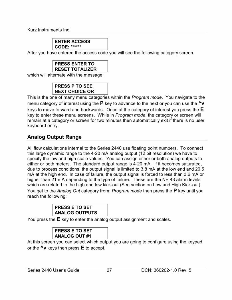
ENTER ACCESSCODE: ******
After you have entered the access code you will see the following category screen.
PRESS ENTER TORESET TOTALIZER
which will alternate with the message:
PRESS P TO SEENEXT CHOICE OR
This is the one of many menu categories within the Program mode. You navigate to themenu category of interest using the P key to advance to the next or you can use the ^vkeys to move forward and backwards. Once at the category of interest you press the Ekey to enter these menu screens. While in Program mode, the category or screen willremain at a category or screen for two minutes then automatically exit if there is no userkeyboard entry.
Analog Output Range
All flow calculations internal to the Series 2440 use floating point numbers. To connectthis large dynamic range to the 4-20 mA analog output (12 bit resolution) we have tospecify the low and high scale values. You can assign either or both analog outputs toeither or both meters. The standard output range is 4-20 mA. If it becomes saturated,due to process conditions, the output signal is limited to 3.8 mA at the low end and 20.5mA at the high end. In case of failure, the output signal is forced to less than 3.6 mA orhigher than 21 mA depending to the type of failure. These are the NE 43 alarm levelswhich are related to the high and low kick-out (See section on Low and High Kick-out).You get to the Analog Out category from: Program mode then press the P key until youreach the following:
PRESS E TO SETANALOG OUTPUTS
You press the E key to enter the analog output assignment and scales.
PRESS E TO SETANALOG OUT #1
At this screen you can select which output you are going to configure using the keypador the ^v keys then press E to accept.
Kurz Instruments Inc.
Series 2440 User’s Guide 28 DCN: 360202-1.0 Rev. 5
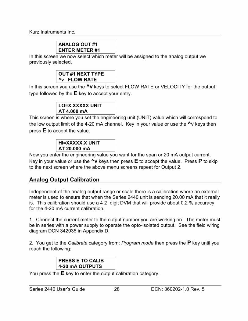
ANALOG OUT #1ENTER METER #1
In this screen we now select which meter will be assigned to the analog output wepreviously selected.
OUT #1 NEXT TYPE^v FLOW RATE
In this screen you use the ^v keys to select FLOW RATE or VELOCITY for the outputtype followed by the E key to accept your entry.
LO=X.XXXXX UNITAT 4.000 mA
This screen is where you set the engineering unit (UNIT) value which will correspond tothe low output limit of the 4-20 mA channel. Key in your value or use the ^v keys thenpress E to accept the value.
HI=XXXXX.X UNITAT 20.000 mA
Now you enter the engineering value you want for the span or 20 mA output current. Key in your value or use the ^v keys then press E to accept the value. Press P to skipto the next screen where the above menu screens repeat for Output 2.
Analog Output Calibration
Independent of the analog output range or scale there is a calibration where an externalmeter is used to ensure that when the Series 2440 unit is sending 20.00 mA that it reallyis. This calibration should use a 4 2 digit DVM that will provide about 0.2 % accuracyfor the 4-20 mA current calibration.
1. Connect the current meter to the output number you are working on. The meter mustbe in series with a power supply to operate the opto-isolated output. See the field wiringdiagram DCN 342035 in Appendix D.
2. You get to the Calibrate category from: Program mode then press the P key until youreach the following:
PRESS E TO CALIB4-20 mA OUTPUTS
You press the E key to enter the output calibration category.
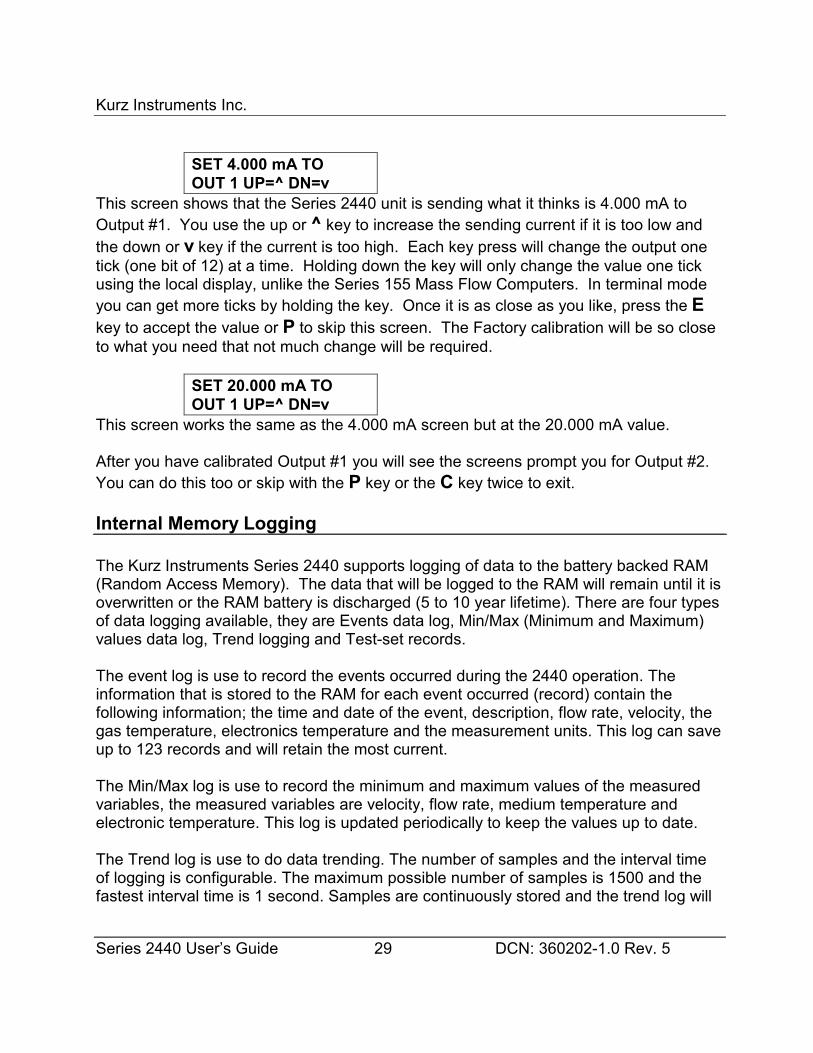
Kurz Instruments Inc.
Series 2440 User’s Guide 29 DCN: 360202-1.0 Rev. 5
SET 4.000 mA TOOUT 1 UP=^ DN=v
This screen shows that the Series 2440 unit is sending what it thinks is 4.000 mA toOutput #1. You use the up or ^ key to increase the sending current if it is too low andthe down or v key if the current is too high. Each key press will change the output onetick (one bit of 12) at a time. Holding down the key will only change the value one tickusing the local display, unlike the Series 155 Mass Flow Computers. In terminal modeyou can get more ticks by holding the key. Once it is as close as you like, press the Ekey to accept the value or P to skip this screen. The Factory calibration will be so closeto what you need that not much change will be required.
SET 20.000 mA TOOUT 1 UP=^ DN=v
This screen works the same as the 4.000 mA screen but at the 20.000 mA value.
After you have calibrated Output #1 you will see the screens prompt you for Output #2. You can do this too or skip with the P key or the C key twice to exit.
Internal Memory Logging
The Kurz Instruments Series 2440 supports logging of data to the battery backed RAM(Random Access Memory). The data that will be logged to the RAM will remain until it isoverwritten or the RAM battery is discharged (5 to 10 year lifetime). There are four typesof data logging available, they are Events data log, Min/Max (Minimum and Maximum)values data log, Trend logging and Test-set records.
The event log is use to record the events occurred during the 2440 operation. Theinformation that is stored to the RAM for each event occurred (record) contain thefollowing information; the time and date of the event, description, flow rate, velocity, thegas temperature, electronics temperature and the measurement units. This log can saveup to 123 records and will retain the most current.
The Min/Max log is use to record the minimum and maximum values of the measuredvariables, the measured variables are velocity, flow rate, medium temperature andelectronic temperature. This log is updated periodically to keep the values up to date.
The Trend log is use to do data trending. The number of samples and the interval timeof logging is configurable. The maximum possible number of samples is 1500 and thefastest interval time is 1 second. Samples are continuously stored and the trend log will
Kurz Instruments Inc.
Series 2440 User’s Guide 30 DCN: 360202-1.0 Rev. 5
retain the last saved samples. Each sample contains a time and date tag, velocity, flowrate, gas temperature and the measurement units.
The Test-set log is use when recording test samples. The data can be logged manuallyby pressing the E key every time you want to record a sample or automatically byspecifying an interval time between recording of test samples. The recording of sampleswill stop once the number of test samples desired is satisfied. Each sample contains atime and date tag, velocity, flow rate, gas temperature and the measurement units. Thetest-set log is subdivided into different test identification numbers (test ID) andconfigurable to meet the users need.
The internal logging memory space allocation is shown in Figure 2. This figure showshow you trade-off test-set memory for trend memory.
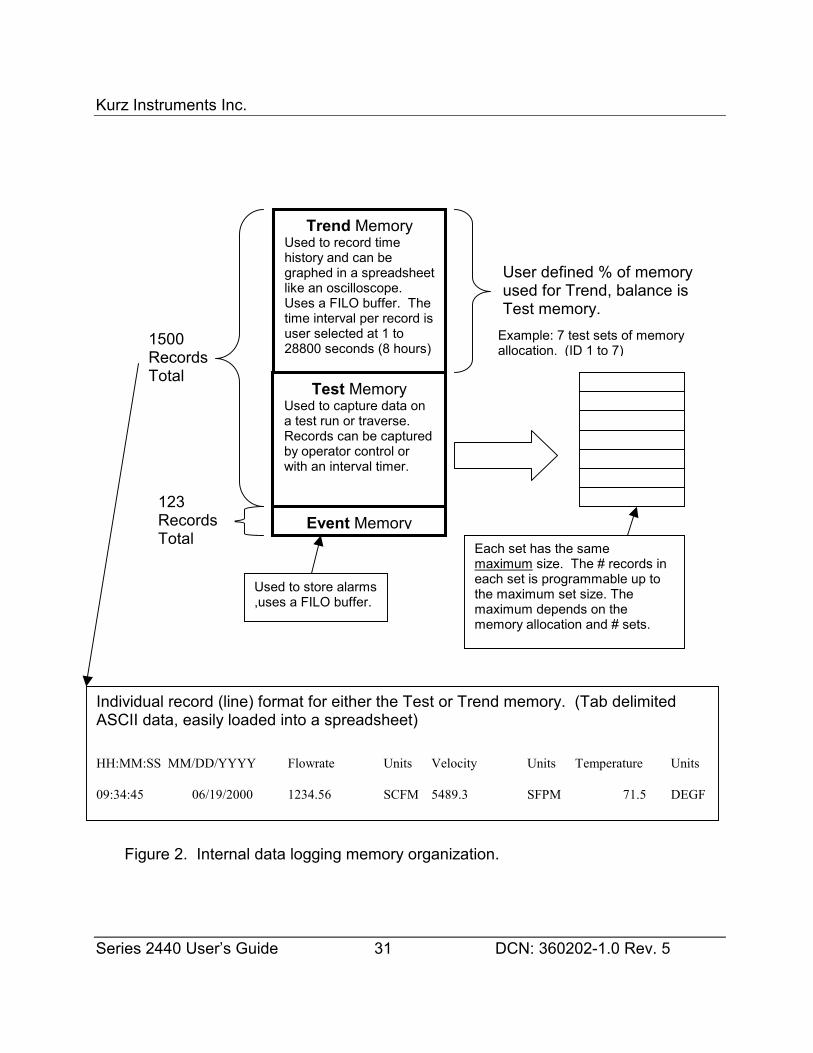
Kurz Instruments Inc.
Series 2440 User’s Guide
Trend MemoryUsed to record timehistory and can begraphed in a spreadsheetlike an oscilloscope. Uses a FILO buffer. Thetime interval per record isuser selected at 1 to28800 seconds (8 hours)
Test MemoryUsed to capture data ona test run or traverse. Records can be capturedby operator control orwith an interval timer.
User defined % of memoryused for Trend, balance is
Individual record (line) formatASCII data, easily loaded into
HH:MM:SS MM/DD/YYYY Flo
09:34:45 06/19/2000 12
Used to,uses a
Figure 2. Internal data lo
Event Memory
1500RecordsTotal
Each set has the same
123RecordsTotal
31
maeacthemame
for either the Test or Tren a spreadsheet)
wrate Units Velocity
34.56 SCFM 5489.3
store alarmsFILO buffer.
gging memory organization
Test memory.Example: 7 test sets of memoryallocation. (ID 1 to 7)
DCN: 360202-1.0 Rev. 5
ximum size. The # records inh set is programmable up to maximum set size. Theximum depends on themory allocation and # sets.
d memory. (Tab delimited
Units Temperature Units
SFPM 71.5 DEGF
.
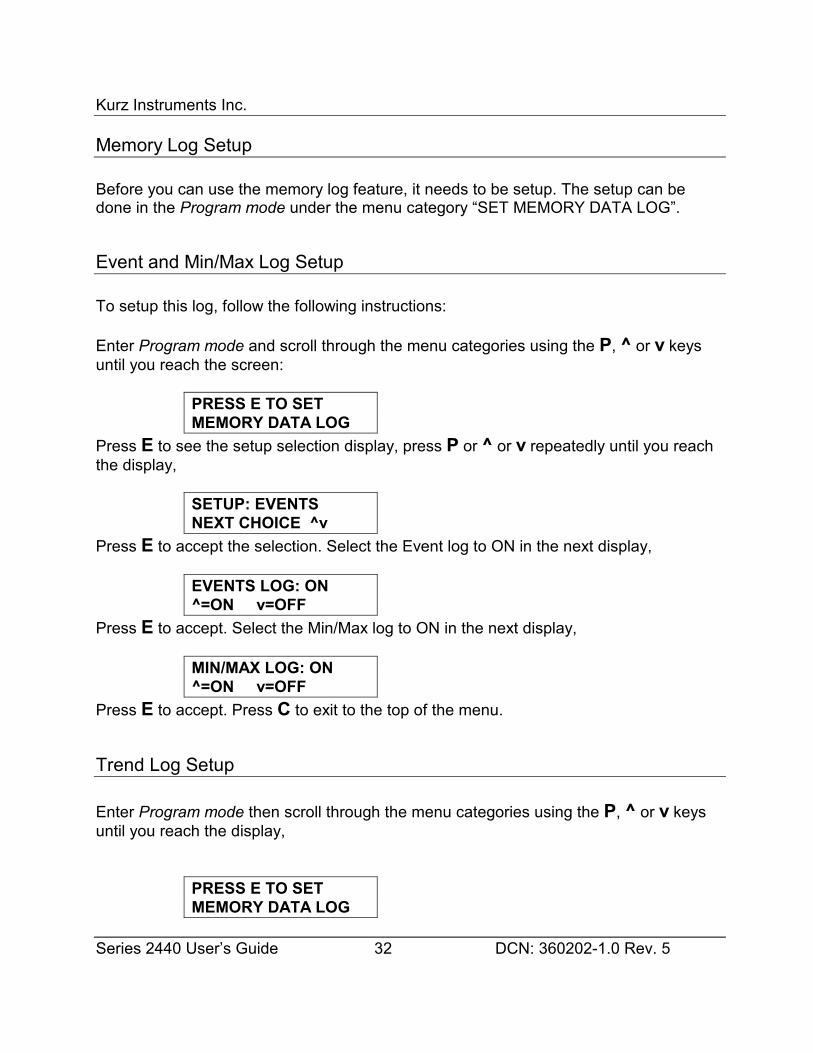
Kurz Instruments Inc.
Series 2440 User’s Guide 32 DCN: 360202-1.0 Rev. 5
Memory Log Setup
Before you can use the memory log feature, it needs to be setup. The setup can bedone in the Program mode under the menu category “SET MEMORY DATA LOG”.
Event and Min/Max Log Setup
To setup this log, follow the following instructions:
Enter Program mode and scroll through the menu categories using the P, ^ or v keysuntil you reach the screen:
PRESS E TO SETMEMORY DATA LOG
Press E to see the setup selection display, press P or ^ or v repeatedly until you reachthe display,
SETUP: EVENTSNEXT CHOICE ^v
Press E to accept the selection. Select the Event log to ON in the next display,
EVENTS LOG: ON^=ON v=OFF
Press E to accept. Select the Min/Max log to ON in the next display,
MIN/MAX LOG: ON^=ON v=OFF
Press E to accept. Press C to exit to the top of the menu.
Trend Log Setup
Enter Program mode then scroll through the menu categories using the P, ^ or v keysuntil you reach the display,
PRESS E TO SETMEMORY DATA LOG
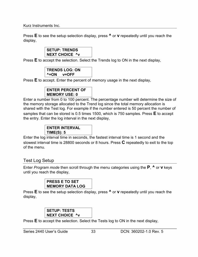
Kurz Instruments Inc.
Series 2440 User’s Guide 33 DCN: 360202-1.0 Rev. 5
Press E to see the setup selection display, press ^ or v repeatedly until you reach thedisplay,
SETUP: TRENDSNEXT CHOICE ^v
Press E to accept the selection. Select the Trends log to ON in the next display,
TRENDS LOG: ON^=ON v=OFF
Press E to accept. Enter the percent of memory usage in the next display,
ENTER PERCENT OFMEMORY USE: 0
Enter a number from 0 to 100 percent. The percentage number will determine the size ofthe memory storage allocated to the Trend log since the total memory allocation isshared with the Test log. For example if the number entered is 50 percent the number ofsamples that can be stored is 0.5 times 1500, which is 750 samples. Press E to acceptthe entry. Enter the log interval in the next display,
ENTER INTERVALTIME(S): 5
Enter the log interval time in seconds, the fastest interval time is 1 second and theslowest interval time is 28800 seconds or 8 hours. Press C repeatedly to exit to the topof the menu.
Test Log SetupEnter Program mode then scroll through the menu categories using the P, ^ or v keysuntil you reach the display,
PRESS E TO SETMEMORY DATA LOG
Press E to see the setup selection display, press ^ or v repeatedly until you reach thedisplay,
SETUP: TESTSNEXT CHOICE ^v
Press E to accept the selection. Select the Tests log to ON in the next display,
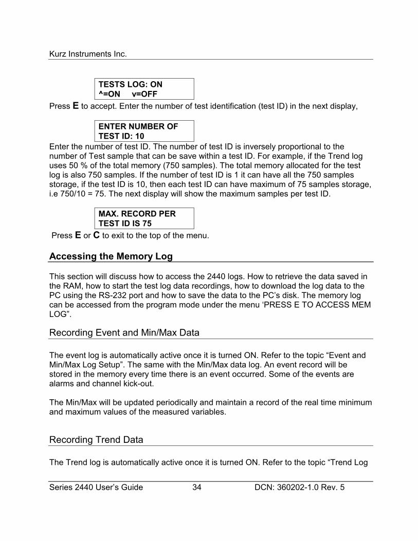
Kurz Instruments Inc.
Series 2440 User’s Guide 34 DCN: 360202-1.0 Rev. 5
TESTS LOG: ON^=ON v=OFF
Press E to accept. Enter the number of test identification (test ID) in the next display,
ENTER NUMBER OFTEST ID: 10
Enter the number of test ID. The number of test ID is inversely proportional to thenumber of Test sample that can be save within a test ID. For example, if the Trend loguses 50 % of the total memory (750 samples). The total memory allocated for the testlog is also 750 samples. If the number of test ID is 1 it can have all the 750 samplesstorage, if the test ID is 10, then each test ID can have maximum of 75 samples storage,i.e 750/10 = 75. The next display will show the maximum samples per test ID.
MAX. RECORD PERTEST ID IS 75
Press E or C to exit to the top of the menu.
Accessing the Memory Log
This section will discuss how to access the 2440 logs. How to retrieve the data saved inthe RAM, how to start the test log data recordings, how to download the log data to thePC using the RS-232 port and how to save the data to the PC’s disk. The memory logcan be accessed from the program mode under the menu ‘PRESS E TO ACCESS MEMLOG”.
Recording Event and Min/Max Data
The event log is automatically active once it is turned ON. Refer to the topic “Event andMin/Max Log Setup”. The same with the Min/Max data log. An event record will bestored in the memory every time there is an event occurred. Some of the events arealarms and channel kick-out.
The Min/Max will be updated periodically and maintain a record of the real time minimumand maximum values of the measured variables.
Recording Trend Data
The Trend log is automatically active once it is turned ON. Refer to the topic “Trend Log
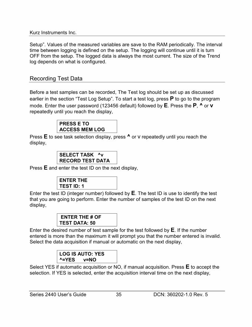
Kurz Instruments Inc.
Series 2440 User’s Guide 35 DCN: 360202-1.0 Rev. 5
Setup”. Values of the measured variables are save to the RAM periodically. The intervaltime between logging is defined on the setup. The logging will continue until it is turnOFF from the setup. The logged data is always the most current. The size of the Trendlog depends on what is configured.
Recording Test Data
Before a test samples can be recorded, The Test log should be set up as discussedearlier in the section “Test Log Setup”. To start a test log, press P to go to the programmode. Enter the user password (123456 default) followed by E. Press the P, ^ or vrepeatedly until you reach the display,
PRESS E TOACCESS MEM LOG
Press E to see task selection display, press ^ or v repeatedly until you reach thedisplay,
SELECT TASK ^vRECORD TEST DATA
Press E and enter the test ID on the next display,
ENTER THETEST ID: 1
Enter the test ID (integer number) followed by E. The test ID is use to identify the testthat you are going to perform. Enter the number of samples of the test ID on the nextdisplay,
ENTER THE # OFTEST DATA: 50
Enter the desired number of test sample for the test followed by E. If the numberentered is more than the maximum it will prompt you that the number entered is invalid.Select the data acquisition if manual or automatic on the next display,
LOG IS AUTO: YES^=YES v=NO
Select YES if automatic acquisition or NO, if manual acquisition. Press E to accept theselection. If YES is selected, enter the acquisition interval time on the next display,
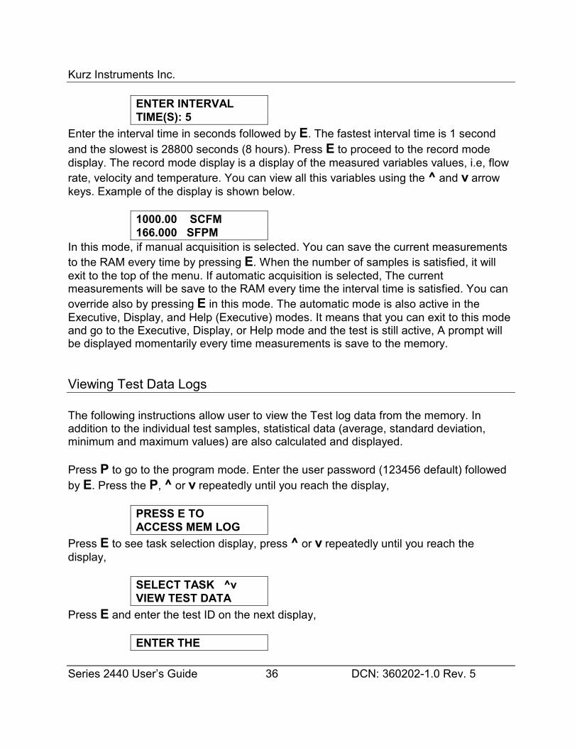
Kurz Instruments Inc.
Series 2440 User’s Guide 36 DCN: 360202-1.0 Rev. 5
ENTER INTERVALTIME(S): 5
Enter the interval time in seconds followed by E. The fastest interval time is 1 secondand the slowest is 28800 seconds (8 hours). Press E to proceed to the record modedisplay. The record mode display is a display of the measured variables values, i.e, flowrate, velocity and temperature. You can view all this variables using the ^ and v arrowkeys. Example of the display is shown below.
1000.00 SCFM166.000 SFPM
In this mode, if manual acquisition is selected. You can save the current measurementsto the RAM every time by pressing E. When the number of samples is satisfied, it willexit to the top of the menu. If automatic acquisition is selected, The currentmeasurements will be save to the RAM every time the interval time is satisfied. You canoverride also by pressing E in this mode. The automatic mode is also active in theExecutive, Display, and Help (Executive) modes. It means that you can exit to this modeand go to the Executive, Display, or Help mode and the test is still active, A prompt willbe displayed momentarily every time measurements is save to the memory.
Viewing Test Data Logs
The following instructions allow user to view the Test log data from the memory. Inaddition to the individual test samples, statistical data (average, standard deviation,minimum and maximum values) are also calculated and displayed.
Press P to go to the program mode. Enter the user password (123456 default) followedby E. Press the P, ^ or v repeatedly until you reach the display,
PRESS E TOACCESS MEM LOG
Press E to see task selection display, press ^ or v repeatedly until you reach thedisplay,
SELECT TASK ^vVIEW TEST DATA
Press E and enter the test ID on the next display,
ENTER THE
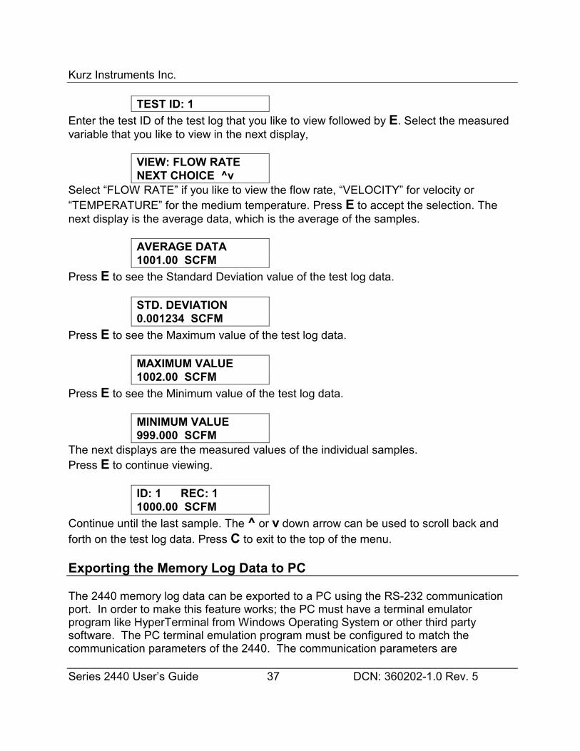
Kurz Instruments Inc.
Series 2440 User’s Guide 37 DCN: 360202-1.0 Rev. 5
TEST ID: 1Enter the test ID of the test log that you like to view followed by E. Select the measuredvariable that you like to view in the next display,
VIEW: FLOW RATENEXT CHOICE ^v
Select “FLOW RATE” if you like to view the flow rate, “VELOCITY” for velocity or“TEMPERATURE” for the medium temperature. Press E to accept the selection. Thenext display is the average data, which is the average of the samples.
AVERAGE DATA1001.00 SCFM
Press E to see the Standard Deviation value of the test log data.
STD. DEVIATION0.001234 SCFM
Press E to see the Maximum value of the test log data.
MAXIMUM VALUE1002.00 SCFM
Press E to see the Minimum value of the test log data.
MINIMUM VALUE999.000 SCFM
The next displays are the measured values of the individual samples.Press E to continue viewing.
ID: 1 REC: 11000.00 SCFM
Continue until the last sample. The ^ or v down arrow can be used to scroll back andforth on the test log data. Press C to exit to the top of the menu.
Exporting the Memory Log Data to PC
The 2440 memory log data can be exported to a PC using the RS-232 communicationport. In order to make this feature works; the PC must have a terminal emulatorprogram like HyperTerminal from Windows Operating System or other third partysoftware. The PC terminal emulation program must be configured to match thecommunication parameters of the 2440. The communication parameters are
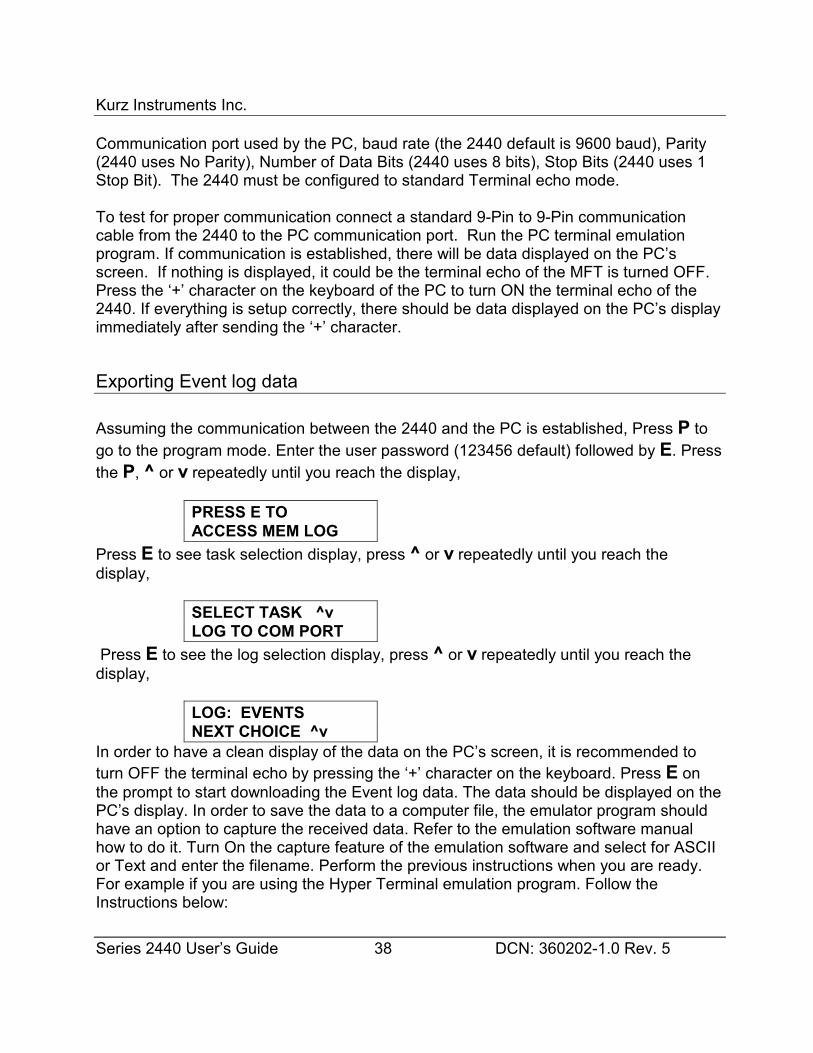
Kurz Instruments Inc.
Series 2440 User’s Guide 38 DCN: 360202-1.0 Rev. 5
Communication port used by the PC, baud rate (the 2440 default is 9600 baud), Parity(2440 uses No Parity), Number of Data Bits (2440 uses 8 bits), Stop Bits (2440 uses 1Stop Bit). The 2440 must be configured to standard Terminal echo mode.
To test for proper communication connect a standard 9-Pin to 9-Pin communicationcable from the 2440 to the PC communication port. Run the PC terminal emulationprogram. If communication is established, there will be data displayed on the PC’sscreen. If nothing is displayed, it could be the terminal echo of the MFT is turned OFF. Press the ‘+’ character on the keyboard of the PC to turn ON the terminal echo of the2440. If everything is setup correctly, there should be data displayed on the PC’s displayimmediately after sending the ‘+’ character.
Exporting Event log data
Assuming the communication between the 2440 and the PC is established, Press P togo to the program mode. Enter the user password (123456 default) followed by E. Pressthe P, ^ or v repeatedly until you reach the display,
PRESS E TOACCESS MEM LOG
Press E to see task selection display, press ^ or v repeatedly until you reach thedisplay,
SELECT TASK ^vLOG TO COM PORT
Press E to see the log selection display, press ^ or v repeatedly until you reach thedisplay,
LOG: EVENTSNEXT CHOICE ^v
In order to have a clean display of the data on the PC’s screen, it is recommended toturn OFF the terminal echo by pressing the ‘+’ character on the keyboard. Press E onthe prompt to start downloading the Event log data. The data should be displayed on thePC’s display. In order to save the data to a computer file, the emulator program shouldhave an option to capture the received data. Refer to the emulation software manualhow to do it. Turn On the capture feature of the emulation software and select for ASCIIor Text and enter the filename. Perform the previous instructions when you are ready.For example if you are using the Hyper Terminal emulation program. Follow theInstructions below:
Kurz Instruments Inc.
Series 2440 User’s Guide 39 DCN: 360202-1.0 Rev. 5
1. Click the Start button on the task bar, select Programs, select Accessories, selectHyperterminal then click Hyper Terminal.
2. From Hyper Terminal program window, a dialog box named “Connection Description”will pop up. Enter the filename of the new connection and choose the appropriateicon. Press OK when ready.
3. Another dialog box named “Connect To” will pop up. Select the propercommunication port for the connection from the “Connect using:” list box entry.Select COM1, COM2 or COM3 which ever port had the physical connection to theunit. Press OK when ready.
4. Another dialog box named “COM? Properties will pop up. On the “Port Setting” tab,configure the following parameters;
5. Bits Per Second: Select whatever the 2440 is using (default is 9600).
Data Bits: set to 8Parity: select NONEStop Bits: select 1Flow Control: select NONE
6. Press OK when ready.
7. If every thing is setup correctly, data should be displayed at the PC’s display. If not,try to press the ‘+’ character on the keyboard. If there is no data displayed on the PC,check the connection and communication parameters.
8. Save the file for future use. To save the file, click the “File” menu and click the Savebutton.
9. To capture the data sent to the terminal, click the “Transfer” from the menu bar, clickthe “Capture Text”. Enter the filename on the dialog box then click the “start” button.
10. At this time all the data that is send to the terminal will be save under the enteredfilename.
11. To stop capturing data, click the “Transfer” from the menu bar, highlight the “CaptureText” and click on “Stop”.
12. Make sure to remember which folder the file is saved.13. You can view the file using the program Wordpad from Windows Operating System.
Exporting Trend log data
Assuming the communication between the 2440 and the PC is established, Press P togo to the program mode. Enter the user password (123456 default) followed by E. Pressthe P, ^ or v repeatedly until you reach the display,
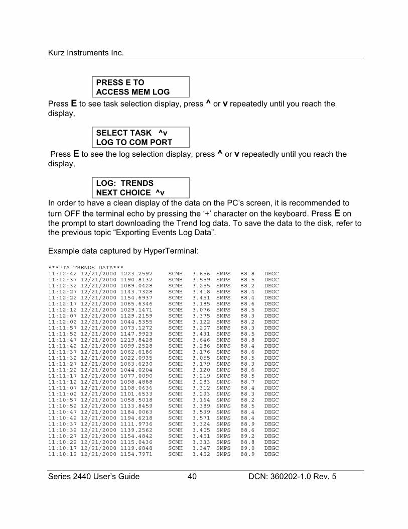
Kurz Instruments Inc.
Series 2440 User’s Guide 40 DCN: 360202-1.0 Rev. 5
PRESS E TOACCESS MEM LOG
Press E to see task selection display, press ^ or v repeatedly until you reach thedisplay,
SELECT TASK ^vLOG TO COM PORT
Press E to see the log selection display, press ^ or v repeatedly until you reach thedisplay,
LOG: TRENDSNEXT CHOICE ^v
In order to have a clean display of the data on the PC’s screen, it is recommended toturn OFF the terminal echo by pressing the ‘+’ character on the keyboard. Press E onthe prompt to start downloading the Trend log data. To save the data to the disk, refer tothe previous topic “Exporting Events Log Data”.
Example data captured by HyperTerminal:
***PTA TRENDS DATA***11:12:42 12/21/2000 1223.2592 SCMH 3.656 SMPS 88.8 DEGC11:12:37 12/21/2000 1190.8132 SCMH 3.559 SMPS 88.5 DEGC11:12:32 12/21/2000 1089.0428 SCMH 3.255 SMPS 88.2 DEGC11:12:27 12/21/2000 1143.7328 SCMH 3.418 SMPS 88.4 DEGC11:12:22 12/21/2000 1154.6937 SCMH 3.451 SMPS 88.4 DEGC11:12:17 12/21/2000 1065.6346 SCMH 3.185 SMPS 88.6 DEGC11:12:12 12/21/2000 1029.1471 SCMH 3.076 SMPS 88.5 DEGC11:12:07 12/21/2000 1129.2159 SCMH 3.375 SMPS 88.3 DEGC11:12:02 12/21/2000 1044.5355 SCMH 3.122 SMPS 88.2 DEGC11:11:57 12/21/2000 1073.1272 SCMH 3.207 SMPS 88.3 DEGC11:11:52 12/21/2000 1147.9923 SCMH 3.431 SMPS 88.5 DEGC11:11:47 12/21/2000 1219.8428 SCMH 3.646 SMPS 88.8 DEGC11:11:42 12/21/2000 1099.2528 SCMH 3.286 SMPS 88.4 DEGC11:11:37 12/21/2000 1062.6186 SCMH 3.176 SMPS 88.6 DEGC11:11:32 12/21/2000 1022.0935 SCMH 3.055 SMPS 88.5 DEGC11:11:27 12/21/2000 1063.6230 SCMH 3.179 SMPS 88.3 DEGC11:11:22 12/21/2000 1044.0204 SCMH 3.120 SMPS 88.6 DEGC11:11:17 12/21/2000 1077.0090 SCMH 3.219 SMPS 88.5 DEGC11:11:12 12/21/2000 1098.4888 SCMH 3.283 SMPS 88.7 DEGC11:11:07 12/21/2000 1108.0636 SCMH 3.312 SMPS 88.4 DEGC11:11:02 12/21/2000 1101.6533 SCMH 3.293 SMPS 88.3 DEGC11:10:57 12/21/2000 1058.5018 SCMH 3.164 SMPS 88.2 DEGC11:10:52 12/21/2000 1133.8459 SCMH 3.389 SMPS 88.5 DEGC11:10:47 12/21/2000 1184.0063 SCMH 3.539 SMPS 88.4 DEGC11:10:42 12/21/2000 1194.6218 SCMH 3.571 SMPS 88.4 DEGC11:10:37 12/21/2000 1111.9736 SCMH 3.324 SMPS 88.9 DEGC11:10:32 12/21/2000 1139.2562 SCMH 3.405 SMPS 88.6 DEGC11:10:27 12/21/2000 1154.4842 SCMH 3.451 SMPS 89.2 DEGC11:10:22 12/21/2000 1115.0436 SCMH 3.333 SMPS 88.8 DEGC11:10:17 12/21/2000 1119.6848 SCMH 3.347 SMPS 89.0 DEGC11:10:12 12/21/2000 1154.7971 SCMH 3.452 SMPS 88.9 DEGC
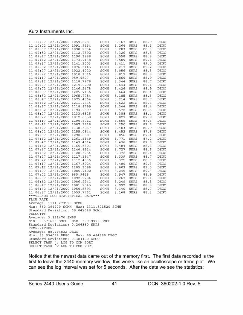
Kurz Instruments Inc.
Series 2440 User’s Guide 41 DCN: 360202-1.0 Rev. 5
11:10:07 12/21/2000 1059.6281 SCMH 3.167 SMPS 88.9 DEGC11:10:02 12/21/2000 1091.9654 SCMH 3.264 SMPS 88.5 DEGC11:09:57 12/21/2000 1098.2934 SCMH 3.283 SMPS 88.3 DEGC11:09:52 12/21/2000 1112.7392 SCMH 3.326 SMPS 88.8 DEGC11:09:47 12/21/2000 1190.3988 SCMH 3.558 SMPS 88.8 DEGC11:09:42 12/21/2000 1173.9438 SCMH 3.509 SMPS 89.1 DEGC11:09:37 12/21/2000 1141.2003 SCMH 3.411 SMPS 89.0 DEGC11:09:32 12/21/2000 1076.3145 SCMH 3.217 SMPS 89.2 DEGC11:09:27 12/21/2000 1022.4020 SCMH 3.056 SMPS 88.8 DEGC11:09:22 12/21/2000 1010.1516 SCMH 3.019 SMPS 88.8 DEGC11:09:17 12/21/2000 959.9527 SCMH 2.869 SMPS 88.9 DEGC11:09:12 12/21/2000 1118.7978 SCMH 3.344 SMPS 88.7 DEGC11:09:07 12/21/2000 1219.0290 SCMH 3.644 SMPS 89.1 DEGC11:09:02 12/21/2000 1146.2478 SCMH 3.426 SMPS 88.9 DEGC11:08:57 12/21/2000 1225.7136 SCMH 3.664 SMPS 88.4 DEGC11:08:52 12/21/2000 1065.7784 SCMH 3.185 SMPS 88.3 DEGC11:08:47 12/21/2000 1075.4364 SCMH 3.214 SMPS 88.7 DEGC11:08:42 12/21/2000 1211.7534 SCMH 3.622 SMPS 88.6 DEGC11:08:37 12/21/2000 1118.8799 SCMH 3.344 SMPS 88.4 DEGC11:08:32 12/21/2000 1194.9697 SCMH 3.572 SMPS 88.6 DEGC11:08:27 12/21/2000 1133.6325 SCMH 3.388 SMPS 88.4 DEGC11:08:22 12/21/2000 1012.6558 SCMH 3.027 SMPS 87.9 DEGC11:08:17 12/21/2000 1190.8711 SCMH 3.559 SMPS 87.8 DEGC11:08:12 12/21/2000 1087.3918 SCMH 3.250 SMPS 87.6 DEGC11:08:07 12/21/2000 1138.3967 SCMH 3.403 SMPS 86.9 DEGC11:08:02 12/21/2000 1155.0944 SCMH 3.452 SMPS 87.6 DEGC11:07:57 12/21/2000 1290.0501 SCMH 3.856 SMPS 87.4 DEGC11:07:52 12/21/2000 1261.5849 SCMH 3.771 SMPS 87.2 DEGC11:07:47 12/21/2000 1149.4514 SCMH 3.436 SMPS 87.9 DEGC11:07:42 12/21/2000 1165.5301 SCMH 3.484 SMPS 88.3 DEGC11:07:37 12/21/2000 1246.8624 SCMH 3.727 SMPS 88.6 DEGC11:07:32 12/21/2000 1128.3254 SCMH 3.372 SMPS 88.4 DEGC11:07:27 12/21/2000 1117.1947 SCMH 3.339 SMPS 88.7 DEGC11:07:22 12/21/2000 1112.4036 SCMH 3.325 SMPS 88.7 DEGC11:07:17 12/21/2000 1167.3924 SCMH 3.489 SMPS 89.3 DEGC11:07:12 12/21/2000 1205.3096 SCMH 3.603 SMPS 89.5 DEGC11:07:07 12/21/2000 1085.7400 SCMH 3.245 SMPS 89.3 DEGC11:07:02 12/21/2000 985.9468 SCMH 2.947 SMPS 88.9 DEGC11:06:57 12/21/2000 1092.9784 SCMH 3.267 SMPS 89.1 DEGC11:06:52 12/21/2000 1086.9941 SCMH 3.249 SMPS 88.8 DEGC11:06:47 12/21/2000 1001.2045 SCMH 2.992 SMPS 88.8 DEGC11:06:42 12/21/2000 1050.5593 SCMH 3.140 SMPS 88.7 DEGC11:06:37 12/21/2000 1059.7761 SCMH 3.168 SMPS 88.2 DEGC***TRENDS LOG STATISTICAL DATA***FLOW RATE:Average: 1111.273520 SCMHMin: 860.394720 SCMH Max: 1311.521520 SCMHStandard Deviation: 69.042648 SCMHVELOCITY:Average: 3.321470 SMPSMin: 2.571623 SMPS Max: 3.919990 SMPSStandard Deviation: 0.206360 SMPSTEMPERATURE:Average: 88.494832 DEGCMin: 86.934072 DEGC Max: 89.484880 DEGCStandard Deviation: 0.384480 DEGCSELECT TASK ^v LOG TO COM PORTSELECT TASK ^v LOG TO COM PORT
Notice that the newest data came out of the memory first. The first data recorded is thefirst to leave the 2440 memory window, this works like an oscilloscope or trend plot. Wecan see the log interval was set for 5 seconds. After the data we see the statistics:
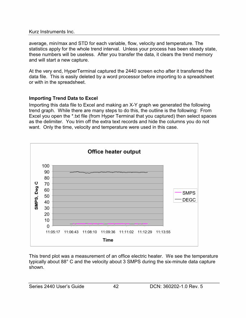
Kurz Instruments Inc.
Series 2440 User’s Guide 42 DCN: 360202-1.0 Rev. 5
average, min/max and STD for each variable, flow, velocity and temperature. Thestatistics apply for the whole trend interval. Unless your process has been steady state,these numbers will be useless. After you transfer the data, it clears the trend memoryand will start a new capture.
At the very end, HyperTerminal captured the 2440 screen echo after it transferred thedata file. This is easily deleted by a word processor before importing to a spreadsheetor with in the spreadsheet.
Importing Trend Data to ExcelImporting this data file to Excel and making an X-Y graph we generated the followingtrend graph. While there are many steps to do this, the outline is the following: FromExcel you open the *.txt file (from Hyper Terminal that you captured) then select spacesas the delimiter. You trim off the extra text records and hide the columns you do notwant. Only the time, velocity and temperature were used in this case.
This trend plot was a measurement of an office electric heater. We see the temperaturetypically about 88° C and the velocity about 3 SMPS during the six-minute data captureshown.
Office heater output
0102030405060708090
100
11:05:17 11:06:43 11:08:10 11:09:36 11:11:02 11:12:29 11:13:55
Time
SMPSDEGC
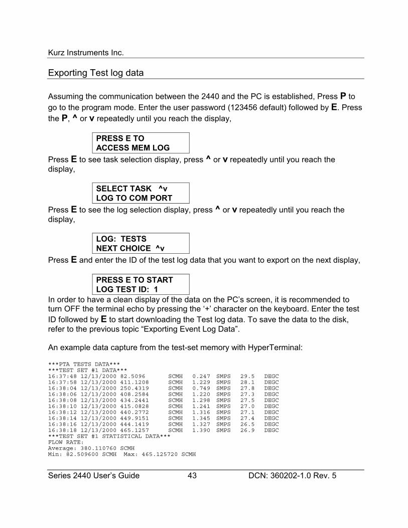
Kurz Instruments Inc.
Series 2440 User’s Guide 43 DCN: 360202-1.0 Rev. 5
Exporting Test log data
Assuming the communication between the 2440 and the PC is established, Press P togo to the program mode. Enter the user password (123456 default) followed by E. Pressthe P, ^ or v repeatedly until you reach the display,
PRESS E TOACCESS MEM LOG
Press E to see task selection display, press ^ or v repeatedly until you reach thedisplay,
SELECT TASK ^vLOG TO COM PORT
Press E to see the log selection display, press ^ or v repeatedly until you reach thedisplay,
LOG: TESTSNEXT CHOICE ^v
Press E and enter the ID of the test log data that you want to export on the next display,
PRESS E TO STARTLOG TEST ID: 1
In order to have a clean display of the data on the PC’s screen, it is recommended toturn OFF the terminal echo by pressing the ‘+’ character on the keyboard. Enter the testID followed by E to start downloading the Test log data. To save the data to the disk,refer to the previous topic “Exporting Event Log Data”.
An example data capture from the test-set memory with HyperTerminal:
***PTA TESTS DATA******TEST SET #1 DATA***16:37:48 12/13/2000 82.5096 SCMH 0.247 SMPS 29.5 DEGC16:37:58 12/13/2000 411.1208 SCMH 1.229 SMPS 28.1 DEGC16:38:04 12/13/2000 250.4319 SCMH 0.749 SMPS 27.8 DEGC16:38:06 12/13/2000 408.2584 SCMH 1.220 SMPS 27.3 DEGC16:38:08 12/13/2000 434.2441 SCMH 1.298 SMPS 27.5 DEGC16:38:10 12/13/2000 415.0828 SCMH 1.241 SMPS 27.0 DEGC16:38:12 12/13/2000 440.2772 SCMH 1.316 SMPS 27.1 DEGC16:38:14 12/13/2000 449.9151 SCMH 1.345 SMPS 27.4 DEGC16:38:16 12/13/2000 444.1419 SCMH 1.327 SMPS 26.5 DEGC16:38:18 12/13/2000 465.1257 SCMH 1.390 SMPS 26.9 DEGC***TEST SET #1 STATISTICAL DATA***FLOW RATE:Average: 380.110760 SCMHMin: 82.509600 SCMH Max: 465.125720 SCMH
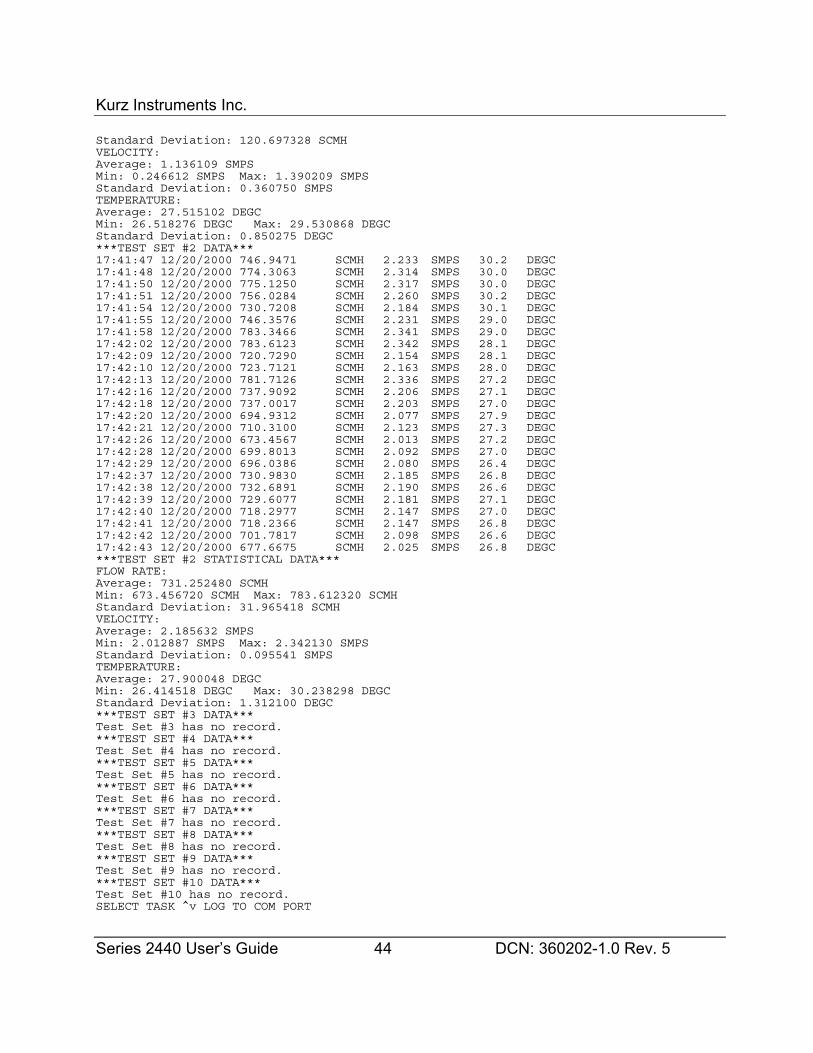
Kurz Instruments Inc.
Series 2440 User’s Guide 44 DCN: 360202-1.0 Rev. 5
Standard Deviation: 120.697328 SCMHVELOCITY:Average: 1.136109 SMPSMin: 0.246612 SMPS Max: 1.390209 SMPSStandard Deviation: 0.360750 SMPSTEMPERATURE:Average: 27.515102 DEGCMin: 26.518276 DEGC Max: 29.530868 DEGCStandard Deviation: 0.850275 DEGC***TEST SET #2 DATA***17:41:47 12/20/2000 746.9471 SCMH 2.233 SMPS 30.2 DEGC17:41:48 12/20/2000 774.3063 SCMH 2.314 SMPS 30.0 DEGC17:41:50 12/20/2000 775.1250 SCMH 2.317 SMPS 30.0 DEGC17:41:51 12/20/2000 756.0284 SCMH 2.260 SMPS 30.2 DEGC17:41:54 12/20/2000 730.7208 SCMH 2.184 SMPS 30.1 DEGC17:41:55 12/20/2000 746.3576 SCMH 2.231 SMPS 29.0 DEGC17:41:58 12/20/2000 783.3466 SCMH 2.341 SMPS 29.0 DEGC17:42:02 12/20/2000 783.6123 SCMH 2.342 SMPS 28.1 DEGC17:42:09 12/20/2000 720.7290 SCMH 2.154 SMPS 28.1 DEGC17:42:10 12/20/2000 723.7121 SCMH 2.163 SMPS 28.0 DEGC17:42:13 12/20/2000 781.7126 SCMH 2.336 SMPS 27.2 DEGC17:42:16 12/20/2000 737.9092 SCMH 2.206 SMPS 27.1 DEGC17:42:18 12/20/2000 737.0017 SCMH 2.203 SMPS 27.0 DEGC17:42:20 12/20/2000 694.9312 SCMH 2.077 SMPS 27.9 DEGC17:42:21 12/20/2000 710.3100 SCMH 2.123 SMPS 27.3 DEGC17:42:26 12/20/2000 673.4567 SCMH 2.013 SMPS 27.2 DEGC17:42:28 12/20/2000 699.8013 SCMH 2.092 SMPS 27.0 DEGC17:42:29 12/20/2000 696.0386 SCMH 2.080 SMPS 26.4 DEGC17:42:37 12/20/2000 730.9830 SCMH 2.185 SMPS 26.8 DEGC17:42:38 12/20/2000 732.6891 SCMH 2.190 SMPS 26.6 DEGC17:42:39 12/20/2000 729.6077 SCMH 2.181 SMPS 27.1 DEGC17:42:40 12/20/2000 718.2977 SCMH 2.147 SMPS 27.0 DEGC17:42:41 12/20/2000 718.2366 SCMH 2.147 SMPS 26.8 DEGC17:42:42 12/20/2000 701.7817 SCMH 2.098 SMPS 26.6 DEGC17:42:43 12/20/2000 677.6675 SCMH 2.025 SMPS 26.8 DEGC***TEST SET #2 STATISTICAL DATA***FLOW RATE:Average: 731.252480 SCMHMin: 673.456720 SCMH Max: 783.612320 SCMHStandard Deviation: 31.965418 SCMHVELOCITY:Average: 2.185632 SMPSMin: 2.012887 SMPS Max: 2.342130 SMPSStandard Deviation: 0.095541 SMPSTEMPERATURE:Average: 27.900048 DEGCMin: 26.414518 DEGC Max: 30.238298 DEGCStandard Deviation: 1.312100 DEGC***TEST SET #3 DATA***Test Set #3 has no record.***TEST SET #4 DATA***Test Set #4 has no record.***TEST SET #5 DATA***Test Set #5 has no record.***TEST SET #6 DATA***Test Set #6 has no record.***TEST SET #7 DATA***Test Set #7 has no record.***TEST SET #8 DATA***Test Set #8 has no record.***TEST SET #9 DATA***Test Set #9 has no record.***TEST SET #10 DATA***Test Set #10 has no record.SELECT TASK ^v LOG TO COM PORT
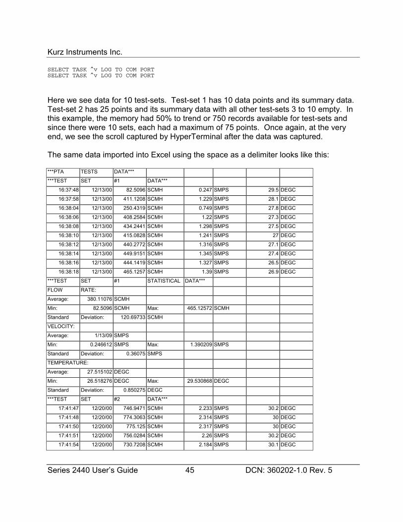
Kurz Instruments Inc.
Series 2440 User’s Guide 45 DCN: 360202-1.0 Rev. 5
SELECT TASK ^v LOG TO COM PORTSELECT TASK ^v LOG TO COM PORT
Here we see data for 10 test-sets. Test-set 1 has 10 data points and its summary data. Test-set 2 has 25 points and its summary data with all other test-sets 3 to 10 empty. Inthis example, the memory had 50% to trend or 750 records available for test-sets andsince there were 10 sets, each had a maximum of 75 points. Once again, at the veryend, we see the scroll captured by HyperTerminal after the data was captured.
The same data imported into Excel using the space as a delimiter looks like this:
***PTA TESTS DATA***
***TEST SET #1 DATA***
16:37:48 12/13/00 82.5096 SCMH 0.247 SMPS 29.5 DEGC
16:37:58 12/13/00 411.1208 SCMH 1.229 SMPS 28.1 DEGC
16:38:04 12/13/00 250.4319 SCMH 0.749 SMPS 27.8 DEGC
16:38:06 12/13/00 408.2584 SCMH 1.22 SMPS 27.3 DEGC
16:38:08 12/13/00 434.2441 SCMH 1.298 SMPS 27.5 DEGC
16:38:10 12/13/00 415.0828 SCMH 1.241 SMPS 27 DEGC
16:38:12 12/13/00 440.2772 SCMH 1.316 SMPS 27.1 DEGC
16:38:14 12/13/00 449.9151 SCMH 1.345 SMPS 27.4 DEGC
16:38:16 12/13/00 444.1419 SCMH 1.327 SMPS 26.5 DEGC
16:38:18 12/13/00 465.1257 SCMH 1.39 SMPS 26.9 DEGC
***TEST SET #1 STATISTICAL DATA***
FLOW RATE:
Average: 380.11076 SCMH
Min: 82.5096 SCMH Max: 465.12572 SCMH
Standard Deviation: 120.69733 SCMH
VELOCITY:
Average: 1/13/09 SMPS
Min: 0.246612 SMPS Max: 1.390209 SMPS
Standard Deviation: 0.36075 SMPS
TEMPERATURE:
Average: 27.515102 DEGC
Min: 26.518276 DEGC Max: 29.530868 DEGC
Standard Deviation: 0.850275 DEGC
***TEST SET #2 DATA***
17:41:47 12/20/00 746.9471 SCMH 2.233 SMPS 30.2 DEGC
17:41:48 12/20/00 774.3063 SCMH 2.314 SMPS 30 DEGC
17:41:50 12/20/00 775.125 SCMH 2.317 SMPS 30 DEGC
17:41:51 12/20/00 756.0284 SCMH 2.26 SMPS 30.2 DEGC
17:41:54 12/20/00 730.7208 SCMH 2.184 SMPS 30.1 DEGC
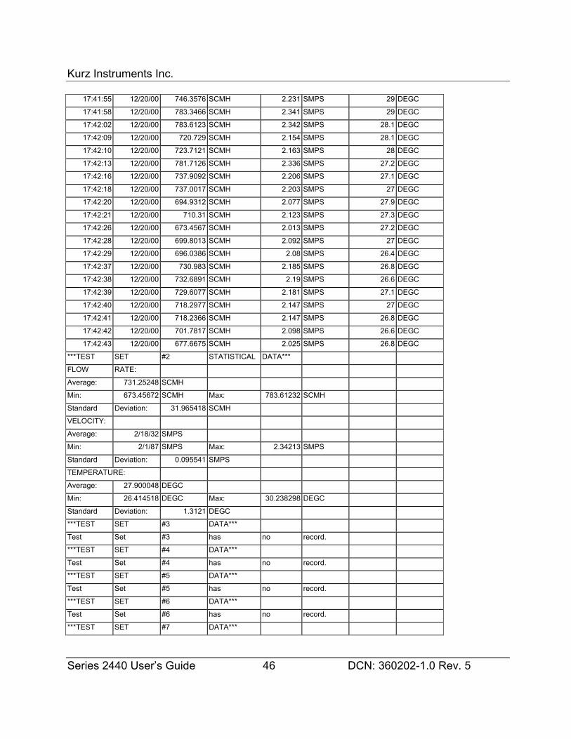
Kurz Instruments Inc.
Series 2440 User’s Guide 46 DCN: 360202-1.0 Rev. 5
17:41:55 12/20/00 746.3576 SCMH 2.231 SMPS 29 DEGC
17:41:58 12/20/00 783.3466 SCMH 2.341 SMPS 29 DEGC
17:42:02 12/20/00 783.6123 SCMH 2.342 SMPS 28.1 DEGC
17:42:09 12/20/00 720.729 SCMH 2.154 SMPS 28.1 DEGC
17:42:10 12/20/00 723.7121 SCMH 2.163 SMPS 28 DEGC
17:42:13 12/20/00 781.7126 SCMH 2.336 SMPS 27.2 DEGC
17:42:16 12/20/00 737.9092 SCMH 2.206 SMPS 27.1 DEGC
17:42:18 12/20/00 737.0017 SCMH 2.203 SMPS 27 DEGC
17:42:20 12/20/00 694.9312 SCMH 2.077 SMPS 27.9 DEGC
17:42:21 12/20/00 710.31 SCMH 2.123 SMPS 27.3 DEGC
17:42:26 12/20/00 673.4567 SCMH 2.013 SMPS 27.2 DEGC
17:42:28 12/20/00 699.8013 SCMH 2.092 SMPS 27 DEGC
17:42:29 12/20/00 696.0386 SCMH 2.08 SMPS 26.4 DEGC
17:42:37 12/20/00 730.983 SCMH 2.185 SMPS 26.8 DEGC
17:42:38 12/20/00 732.6891 SCMH 2.19 SMPS 26.6 DEGC
17:42:39 12/20/00 729.6077 SCMH 2.181 SMPS 27.1 DEGC
17:42:40 12/20/00 718.2977 SCMH 2.147 SMPS 27 DEGC
17:42:41 12/20/00 718.2366 SCMH 2.147 SMPS 26.8 DEGC
17:42:42 12/20/00 701.7817 SCMH 2.098 SMPS 26.6 DEGC
17:42:43 12/20/00 677.6675 SCMH 2.025 SMPS 26.8 DEGC
***TEST SET #2 STATISTICAL DATA***
FLOW RATE:
Average: 731.25248 SCMH
Min: 673.45672 SCMH Max: 783.61232 SCMH
Standard Deviation: 31.965418 SCMH
VELOCITY:
Average: 2/18/32 SMPS
Min: 2/1/87 SMPS Max: 2.34213 SMPS
Standard Deviation: 0.095541 SMPS
TEMPERATURE:
Average: 27.900048 DEGC
Min: 26.414518 DEGC Max: 30.238298 DEGC
Standard Deviation: 1.3121 DEGC
***TEST SET #3 DATA***
Test Set #3 has no record.
***TEST SET #4 DATA***
Test Set #4 has no record.
***TEST SET #5 DATA***
Test Set #5 has no record.
***TEST SET #6 DATA***
Test Set #6 has no record.
***TEST SET #7 DATA***
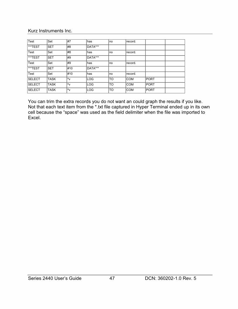
Kurz Instruments Inc.
Series 2440 User’s Guide 47 DCN: 360202-1.0 Rev. 5
Test Set #7 has no record.
***TEST SET #8 DATA***
Test Set #8 has no record.
***TEST SET #9 DATA***
Test Set #9 has no record.
***TEST SET #10 DATA***
Test Set #10 has no record.
SELECT TASK ^v LOG TO COM PORT
SELECT TASK ^v LOG TO COM PORT
SELECT TASK ^v LOG TO COM PORT
You can trim the extra records you do not want an could graph the results if you like. Not that each text item from the *.txt file captured in Hyper Terminal ended up in its owncell because the “space” was used as the field delimiter when the file was imported toExcel.
Kurz Instruments Inc.
Series 2440 User’s Guide 48 DCN: 360202-1.0 Rev. 5
Flow CalibrationCalibration of the 2440
The basic flow element calibration is done at the Factory but can be redone at any flowcalibration lab. This data is standard velocity for insertion flow elements and standardvolumetric flow or mass flow for in-line flow elements.
The 2440 velocity calibration data is stored on an EEPROM but can be user modifiedusing the correction factors under Program mode. You can also change the referenceconditions or units of the displayed data in Program mode.
It is important to know that the unit is sold with non-hazardous gas calibrations only. (Air,O2, N2, Ar, CO2, He). In general, the heat transfer for cooling effect measured with thethermal anemometer scales with the molecular weight of the gas and is strongly affectedby the number of hydrogen atoms hanging off the molecule. While any gas can bemeasured with the device, we do not offer calibrations of the other gases as the safetyapprovals are not possible with the Series 2440 for hazardous gases. The Kurz 490 hasan intrinsically safe approval calibrated for Air and could be used in any gas. See ourwebsite for more info.
Using the 2440 for Field Calibration
Field calibration process permits a system to not only have a repeatable reading butabsolute accuracy. Two popular field calibration procedures at Kurz are:
Velocity Traverse andTracer Gas Dilution
The traverse is a classic method and has been documented by many standardsorganizations and a summary can be found in Appendix H. This summary applies toboth round and rectangular ducts.
The tracer gas method is not as common but has many advantages:
Kurz Instruments Inc.
Series 2440 User’s Guide 49 DCN: 360202-1.0 Rev. 5
� Independent of flow measurement technology to thermal or differentialpressure,
� Insensitive to flow profiles,� Insensitive to process pressure and temperature,� Insensitive to many process fluid mixtures or variations in such.
The only down side for the tracer method is the special equipment needed to perform it. You can find more on the tracer gas method at our website under Technical Paper364011.
A Kurz thermal anemometer system will provide a repeatable reading if properly installedfor the specific application without the field calibration. If accuracy is needed, then thefield calibration is required.
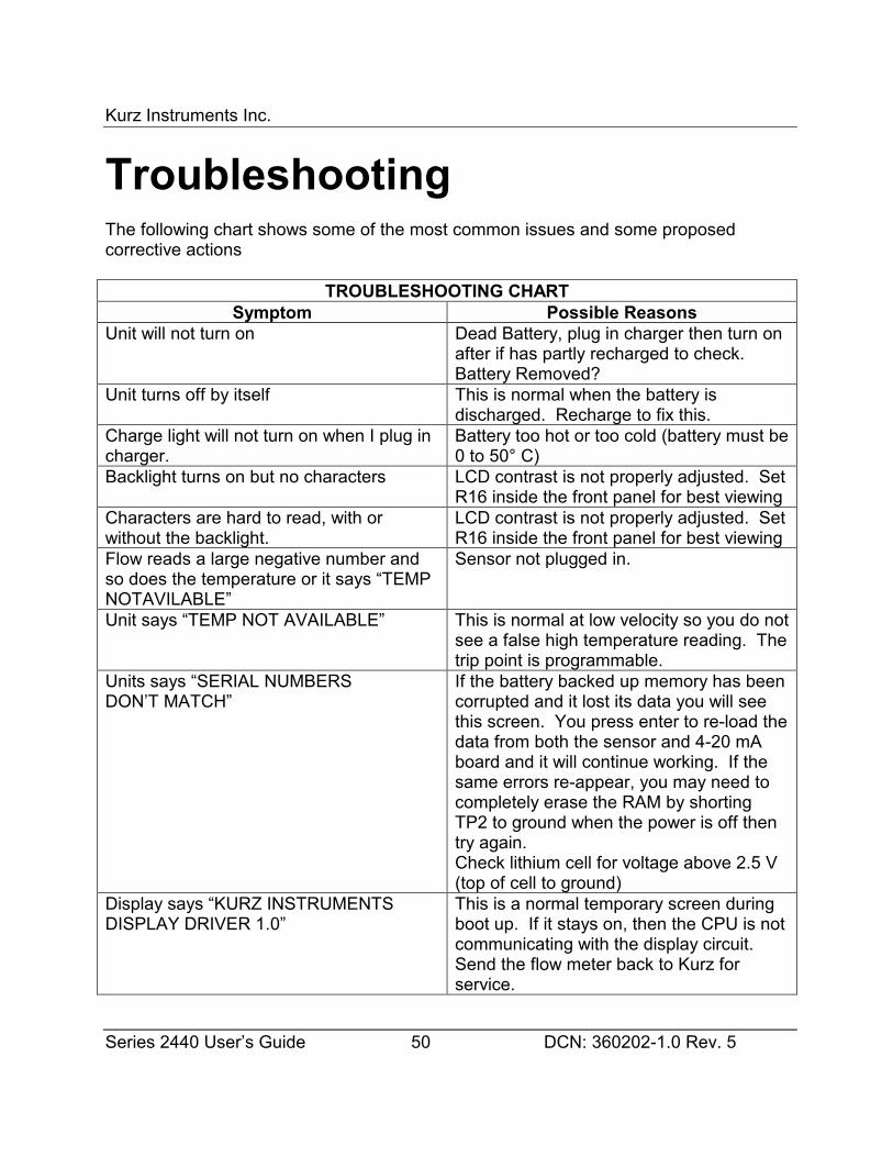
Kurz Instruments Inc.
Series 2440 User’s Guide 50 DCN: 360202-1.0 Rev. 5
TroubleshootingThe following chart shows some of the most common issues and some proposedcorrective actions
TROUBLESHOOTING CHARTSymptom Possible Reasons
Unit will not turn on Dead Battery, plug in charger then turn onafter if has partly recharged to check.Battery Removed?
Unit turns off by itself This is normal when the battery isdischarged. Recharge to fix this.
Charge light will not turn on when I plug incharger.
Battery too hot or too cold (battery must be0 to 50° C)
Backlight turns on but no characters LCD contrast is not properly adjusted. SetR16 inside the front panel for best viewing
Characters are hard to read, with orwithout the backlight.
LCD contrast is not properly adjusted. SetR16 inside the front panel for best viewing
Flow reads a large negative number andso does the temperature or it says “TEMPNOTAVILABLE”
Sensor not plugged in.
Unit says “TEMP NOT AVAILABLE” This is normal at low velocity so you do notsee a false high temperature reading. Thetrip point is programmable.
Units says “SERIAL NUMBERSDON’T MATCH”
If the battery backed up memory has beencorrupted and it lost its data you will seethis screen. You press enter to re-load thedata from both the sensor and 4-20 mAboard and it will continue working. If thesame errors re-appear, you may need tocompletely erase the RAM by shortingTP2 to ground when the power is off thentry again.Check lithium cell for voltage above 2.5 V(top of cell to ground)
Display says “KURZ INSTRUMENTSDISPLAY DRIVER 1.0”
This is a normal temporary screen duringboot up. If it stays on, then the CPU is notcommunicating with the display circuit.Send the flow meter back to Kurz forservice.
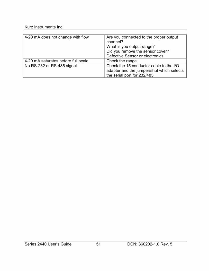
Kurz Instruments Inc.
Series 2440 User’s Guide 51 DCN: 360202-1.0 Rev. 5
4-20 mA does not change with flow Are you connected to the proper outputchannel?What is you output range?Did you remove the sensor cover?Defective Sensor or electronics
4-20 mA saturates before full scale Check the range.No RS-232 or RS-485 signal Check the 15 conductor cable to the I/O
adapter and the jumper/shut which selectsthe serial port for 232/485
Kurz Instruments Inc.
Series 2440 User’s Guide 52 DCN: 360202-1.0 Rev. 5
Return ShipmentRMA (Return Material Authorization) Number
If you believe your unit is not working properly, contact the Kurz Customer ServiceDepartment at: (831) 646-5911 or send E-mail to [email protected] . Please have the following information ready to give to the Kurz Customer ServiceRepresentative :
• Defective unit’s model number and serial number,
• Detailed description of application and type of environment unit is being used in,
• Detailed description of perceived problem,
• Type of gas, Flow range, and standard conditions unit is to be recalibrated at,
• Any special QA requirements (nuclear or military application, oxygen service,special calibration or certification etc),
• Technical contact’s name and phone number,
• Billing contact’s name and phone number,
• Complete shipping address,
• Complete billing address.
You will then be issued an RMA number. Kurz personnel will refuse to accept returnmaterial shipments if an RMA number is not visible on the outside surface of theshipping container.
Cleaning of Material to be Returned
Thoroughly clean all material to be returned to Kurz. Because we serve a diversecustomer base, there is a risk of receiving contaminated returned material from ourcustomers. When uncleaned material is received at Kurz, the customer will becontacted to arrange at their expense for the material to be picked up from Kurz
Kurz Instruments Inc.
Series 2440 User’s Guide 53 DCN: 360202-1.0 Rev. 5
and cleaned before Kurz personnel handle the equipment.
Shipping Material to be Returned
Securely package cleaned material (When uncleaned material is received at Kurz,the customer will be contacted to arrange at their expense for the material to bepicked up from Kurz and cleaned before Kurz personnel handle the equipment)along with a packing slip referencing the RMA number, model number and serial numberin a sturdy container with the return address and RMA number clearly marked on theoutside surface of the container. Kurz personnel will refuse to accept return materialshipments if an RMA number is not visible on the outside surface of the shippingcontainer.
Ship pre-paid to the following address:
KURZ INSTRUMENTS INCCUSTOMER SERVICE DEPT2411 GARDEN RDMONTEREY CA 93940-5394USA
Kurz Instruments Inc.
Series 2440 User’s Guide 54 DCN: 360202-1.0 Rev. 5
GLOSSARYASCII The is the American Standard Character Information Interchange binary code for
characters. It is also a version of the Modbus protocol that uses hex-decimalcharacter representation of the RTU format, for two bytes per one used with theRTU.
CORRECTION FACTOR: For insertion flow transmitters this is a number typicallybetween 0.7 and 1.0 needed to convert a point velocity reading to the true ductaverage. This number is velocity or flow rate dependent. It can also be used totrim an in-line flow transmitter but the numbers are much closer to unity since thevelocity profile information is built into the calibration.
DEGC: Degrees Celsius.
DEGF: Degrees Fahrenheit.
DISPLAY MODE: The set of display menus for viewing the meter readings.
EEPROM: Nonvolatile solid state memory device.
EXECUTIVE MODE: This is the menu-state the flow meter starts in. You branch toDisplay Mode, Program Mode or can view the meter summaries from their scroll.
FLASH MEMORY: Nonvolatile reprogrammable solid state memory device used forprogram memory.
KGH: Kilograms-per-Hour
KGM: Kilograms-per-Minute
L/D: This is the Length to Diameter ratio in a pipe or duct between two locations. Thisnon dimensional parameter is a comparative metric used to measure the distancebetween a flow disturbance and a measurement point. Both upstream, anddownstream values are needed to quantify an installation.
LCD: Liquid Crystal Display. A 2 line by 16 character, back-lit display is used on theSeries 2440 for visibility in dark areas.
MASS FLOW: Mass per unit time (i.e. Kg/s). This is the standard volumetric flowmultiplied by the standard density.
Kurz Instruments Inc.
Series 2440 User’s Guide 55 DCN: 360202-1.0 Rev. 5
MENU CATEGORY: The top level screens within program or display mode are menucategories.
MENU SCREEN: Any screen where data is presented or can be changed. Menuscreens are found within or under the menu categories.
MENU-STATE: A viewing or display screen of the LCD. See drawing in the Appendix fora comprehensive listing of the menu-states.
METER: A virtual single task device which measures an engineering value and maytotalize its rate.
PARSE: This is the text processing algorithm required to separate data values from astring of data.
PLC Programmable Logic Controller. These dedicated computers are configured to doa task and can read/write data to digital and analog devices.
PPH: Pounds-per-Hour.
PPM: Pounds-per-Minute.
PROFILE: See Velocity Profile.
PROGRAM MODE: The set of display menus for programming or configuring the meter.
PSIA: Pounds per Square Inch, Absolute pressure reference.
REBOOT: When a computer restarts there is a delay from the power on until it isoperating normally. During this time it is loading its programs, doing some testingand initializing things. For the Series MFT this takes about seven seconds.
RTU: This is the Remote Terminal Unit Modbus protocol. It is a binary formatted datapacket with address, command data packet size and data. See thehttp://www.modicon.com/ website for the on line version of the specification, PI-MBUS-300
SBCF: Sensor Blockage Correction Factor. This is the geometric projection of thesensor element and probe support area subtracted from the duct area, thisquantity normalized by the duct area.
Kurz Instruments Inc.
Series 2440 User’s Guide 56 DCN: 360202-1.0 Rev. 5
SCFH: Standard Cubic Feet-per-Hour.
SCFM: Standard Cubic Feet-per-Minute.
SCMH: Standard Cubic Meters-per-Hour.
SCMM: Standard Cubic Meters-per-Minute.
SCMS: Standard Cubic Meters-per-Second.
SFPM: Standard Feet-per-Minute.
SMPS: Standard Meters-per-Second.
SPECIFIC HUMIDITY: The absolute ratio of water mass to dry Air mass is the specifichumidity ω. The saturation point of water vapor in Air is temperature dependent. The percentage water vapor compared to the saturation point is known as relativehumidity given in a percentage by the weather forecasters.
STANDARD VELOCITY: is the ρv product normalized to a standard density.Standard Velocity = ρv/ρs with units of velocitywhere ρ=is the actual density, v is the actual velocity and=ρs is the standard gasdensity. For air this is 0.07387 lb/ft3 at 25 °C and 29.92 in Hg.
STANDARD VOLUMETRIC FLOW: is the ρv product multiplied by an area (like a pipecross section), normalized to a standard density.Standard Volumetric Flow = Area x (Standard Velocity)
= Aρv/ρswhere ρ=is the actual density, v is the actual velocity and=ρs is the standard gasdensity and A is the area.
VELOCITY PROFILE: Due to drag and viscous fluid flow, the velocity in a duct tends tobe its highest in the center and goes to zero at the duct walls. This shape isbullet nose at low velocities known as laminar, and flattens out at the higher moreturbulent flow rates. A velocity dependent correction factor is measured based onan in-situ calibration to accurately convert the sensors velocity reading to the trueaverage for computing flow or mass flow.
VTM: Velocity Temperature Mapping. This is a calibration method where data at severaltemperatures are loaded into the flow meter. Flow signal linearization and theninterpolation between the different temperature data sets are performed. This

Kurz Instruments Inc.
Series 2440 User’s Guide 57 DCN: 360202-1.0 Rev. 5
method is a second order correction to the sensors response and provides amore accurate temperature compensated flow measurement.

Kurz Instruments Inc.
Series 2440 User’s Guide 58 DCN: 360202-1.0 Rev. 5
Appendix AThermal AnemometerMeasurementsThe Kurz thermal anemometers use two RTDs, one heated 50 to 100 °C above theambient, the other monitors the ambient. The current required to keep the velocityelement heated is the parameter calibrated in our wind tunnels.
Mass Rate
What does a thermal flow sensor measure? Because of the equations of forcedconvective heat transfer, the output of any thermal anemometer is proportional to thesensor=s Reynolds number (Re). Looking at the Reynolds number we can see how itmeasures mass rate per unit area, NOT volumetric flow rate. Therefore, the thermalanemometer automatically compensates for density.
Because a thermal anemometer measures the unit-area mass flow, it can be said tomeasure mass rate. In other words, it measures the true velocity, weighted by thedensity of the flowing gas. If the mass rate is normalized by a known density, it hasvelocity units, a term known as standard velocity. The next section helps explain wherethese ideas come from.
Mass Flow Equations
Reynolds Number
Lets look at the Reynolds number since it is proportional to the sensor=s power or currentwhen heated X degrees above the ambient:
Re = ρvd/µ
whereρ = actual densityv = actual velocityd = sensor=s diameter
Kurz Instruments Inc.
Series 2440 User’s Guide 59 DCN: 360202-1.0 Rev. 5
µ = gas viscosity
It is the density and velocity (ρv) product that makes the thermal anemometer a massflow meter. Density (ρ) has units of mass/volume and velocity (v) has units oflength/time. So the ρv product has units of (mass/time)/area or mass rate per unit area.
For example:ρ is kg/m3, v is m/s
so ρv is (kg/s)/m2
The sensor is sensitive to the energy that the gas molecules hitting it take away in theform of heat. This energy is proportional to the size and number of molecules that hitthe sensor. It does not know about density and velocity. Small light gas molecules likehydrogen (H2) having a large surface area to mass ratio, are more efficient attransferring the vibrational heat energy of the sensor surface than large heavy moleculeslike Argon (Ar) having a small surface area to mass ratio.
Standard Velocity is the ρv product normalized to a standard density.
Standard Velocity = ρv/ρs
where ρs is the standard gas density. For air this is 0.07387 lb/ft3 at 25 °C and 29.92 inHg.
Note: the density units cancel and you are left with velocity (m/s). Typical units are:Standard Feet Per Minute (SFPM) or Standard Meters Per Second (SMPS). If the gasdensity doubled (you went from 15 PSIA to 30 PSIA) at the same actual velocity, thestandard velocity would double. This also means that if the process gas is at the sametemperature and pressure as the standard condition or the same density, the standardvelocity and actual velocity are identical.
Standard Volumetric Flow is the ρv product multiplied by an area (like a pipe crosssection), normalized to a standard density
Standard Volumetric Flow = Area x (Standard Velocity)= Aρv/ρs
where A is the area:
The units here are volume/time (m3/s)Typical Displayed units are:
SCFM, Standard Cubic Feet-per-MinuteSCMM, Standard Cubic Meters-per-Minute
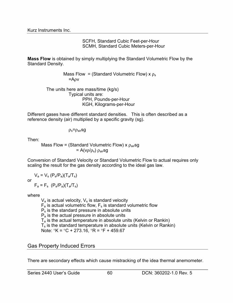
Kurz Instruments Inc.
Series 2440 User’s Guide 60 DCN: 360202-1.0 Rev. 5
SCFH, Standard Cubic Feet-per-HourSCMH, Standard Cubic Meters-per-Hour
Mass Flow is obtained by simply multiplying the Standard Volumetric Flow by theStandard Density.
Mass Flow = (Standard Volumetric Flow) x ρs=Aρv
The units here are mass/time (kg/s)Typical units are:
PPH, Pounds-per-HourKGH, Kilograms-per-Hour
Different gases have different standard densities. This is often described as areference density (air) multiplied by a specific gravity (sg).
ρs=ρairsg
Then:Mass Flow = (Standard Volumetric Flow) x ρairsg
= A(vρ/ρs) ρairsg
Conversion of Standard Velocity or Standard Volumetric Flow to actual requires onlyscaling the result for the gas density according to the ideal gas law.
Va = Vs (Ps/Pa)(Ta/Ts)or
Fa = Fs (Ps/Pa)(Ta/Ts)
whereVa is actual velocity, Vs is standard velocityFa is actual volumetric flow, Fs is standard volumetric flowPs is the standard pressure in absolute unitsPa is the actual pressure in absolute unitsTa is the actual temperature in absolute units (Kelvin or Rankin)Ts is the standard temperature in absolute units (Kelvin or Rankin)Note: °K = °C + 273.16, °R = °F + 459.67
Gas Property Induced Errors
There are secondary effects which cause mistracking of the idea thermal anemometer.
Kurz Instruments Inc.
Series 2440 User’s Guide 61 DCN: 360202-1.0 Rev. 5
• Pressure changes will affect the calibration for some gasses. For example, N2 has alarge 2.5% /100 psi shift in its viscosity which changes its mass flow reading the sameamount. By contrast He has nearly no viscosity change with pressure.
• Temperature changes will affect the gas thermal conductivity and viscosity so thecalibration will drift. This is typically 2.5% /100 °C. The minimum drift occurs near 3000SFPM where the dynamic temperature compensation is performed.
• Temperature profiles in the pipe will produce flow errors. This is caused by usinguninsulated pipe upstream of the sensor where the gas is above or below the ambienttemperature.
• Low flow free convective heat transfer forces compete with forced convective andconductive heat transfer forces for power. This causes measurable errors (dependingon gas type, temperature, pressure, and orientation of sensor to both flow and gravity)starting at about 300 SFPM and becomes significant down at about 100 SFPM.
• Wet vs. Dry Flow Rate: The thermal anemometer responds to all gas moleculeswhich hit it. In the case of water vapor(H20) dissolved in Air, it reads what is know aswet standard volumetric flow or WSCFM. For intake combustion processes you want toknow the dry standard volumetric flow or DSCFM which is 21% O2 so your fuel air ratiocan be properly computed. Knowing the specific humidity ratio ω you can use thefollowing equation up to 5% ω and get results within 1%:
DSCFM = WSCFM x 0.622/(0.622 + ω)
For example. In Monterey California, a typical dew point of 14° C corresponds to 70grains/lb of Air based on the Psychrometric chart. Since there are 7000 grains perpound this is 1% specific humidity (ω = 0.01). Therefore DSCFM = WSCFM x0.622/(0.622 +0.01) = WSCFM x 0.984. In other words, 1.6% if the Air by volume iswater vapor. See the Kurz technical note on our web-site for a derivation of the aboveequation.
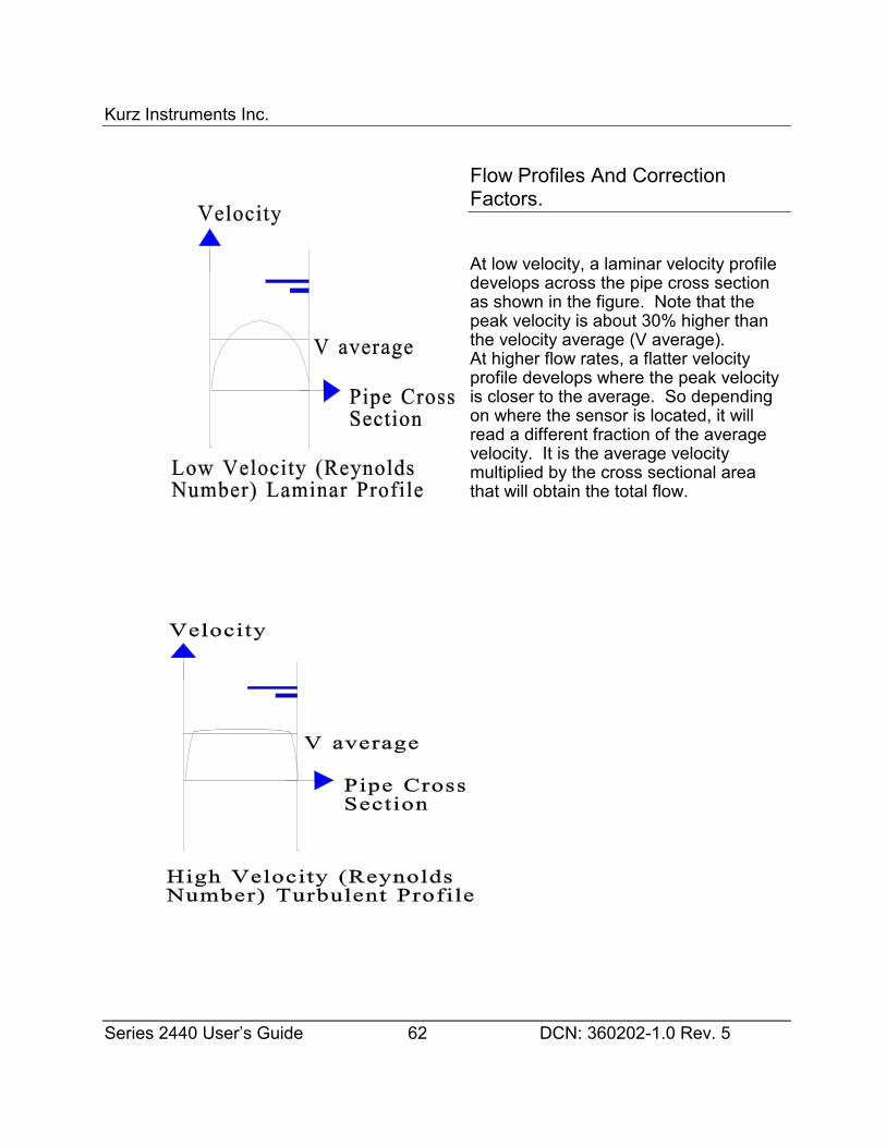
Kurz Instruments Inc.
Series 2440 User’s Guide 62 DCN: 360202-1.0 Rev. 5
Flow Profiles And CorrectionFactors.
At low velocity, a laminar velocity profiledevelops across the pipe cross sectionas shown in the figure. Note that thepeak velocity is about 30% higher thanthe velocity average (V average).At higher flow rates, a flatter velocityprofile develops where the peak velocityis closer to the average. So dependingon where the sensor is located, it willread a different fraction of the averagevelocity. It is the average velocitymultiplied by the cross sectional areathat will obtain the total flow.
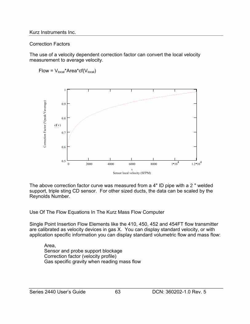
Kurz Instruments Inc.
Series 2440 User’s Guide 63 DCN: 360202-1.0 Rev. 5
Correction Factors
The use of a velocity dependent correction factor can convert the local velocitymeasurement to average velocity.
Flow = Vlocal*Area*cf(Vlocal)
The above correction factor curve was measured from a 4" ID pipe with a 2" weldedsupport, triple sting CD sensor. For other sized ducts, the data can be scaled by theReynolds Number.
Use Of The Flow Equations In The Kurz Mass Flow Computer
Single Point Insertion Flow Elements like the 410, 450, 452 and 454FT flow transmitterare calibrated as velocity devices in gas X. You can display standard velocity, or withapplication specific information you can display standard volumetric flow and mass flow:
Area,Sensor and probe support blockageCorrection factor (velocity profile)Gas specific gravity when reading mass flow
0 2000 4000 6000 8000 1 104 1.2 1040.5
0.6
0.7
0.8
0.9
1
Sensor local velocity (SFPM)
Cor
rect
ion
Fact
or (V
peak
/Vav
erag
e)
cf( )v
v
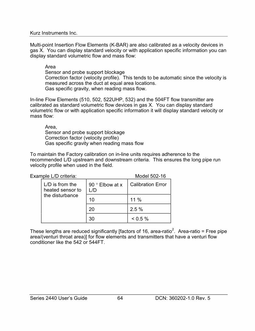
Kurz Instruments Inc.
Series 2440 User’s Guide 64 DCN: 360202-1.0 Rev. 5
Multi-point Insertion Flow Elements (K-BAR) are also calibrated as a velocity devices ingas X. You can display standard velocity or with application specific information you candisplay standard volumetric flow and mass flow:
AreaSensor and probe support blockageCorrection factor (velocity profile). This tends to be automatic since the velocity ismeasured across the duct at equal area locations.Gas specific gravity, when reading mass flow.
In-line Flow Elements (510, 502, 522UHP, 532) and the 504FT flow transmitter arecalibrated as standard volumetric flow devices in gas X. You can display standardvolumetric flow or with application specific information it will display standard velocity ormass flow:
Area,Sensor and probe support blockageCorrection factor (velocity profile)Gas specific gravity when reading mass flow
To maintain the Factory calibration on in-line units requires adherence to therecommended L/D upstream and downstream criteria. This ensures the long pipe runvelocity profile when used in the field.
Example L/D criteria: Model 502-16
90 ° Elbow at xL/D
Calibration Error
10 11 %
20 2.5 %
L/D is from theheated sensor tothe disturbance
30 < 0.5 %
These lengths are reduced significantly [factors of 16, area-ratio2. Area-ratio = Free pipearea/(venturi throat area)] for flow elements and transmitters that have a venturi flowconditioner like the 542 or 544FT.
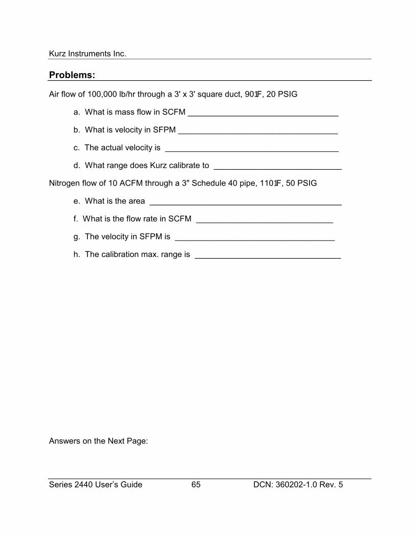
Kurz Instruments Inc.
Series 2440 User’s Guide 65 DCN: 360202-1.0 Rev. 5
Problems:
Air flow of 100,000 lb/hr through a 3' x 3' square duct, 901F, 20 PSIG
a. What is mass flow in SCFM _________________________________
b. What is velocity in SFPM ___________________________________
c. The actual velocity is ______________________________________
d. What range does Kurz calibrate to ____________________________
Nitrogen flow of 10 ACFM through a 3" Schedule 40 pipe, 1101F, 50 PSIG
e. What is the area __________________________________________
f. What is the flow rate in SCFM ______________________________
g. The velocity in SFPM is ___________________________________
h. The calibration max. range is ________________________________
Answers on the Next Page:
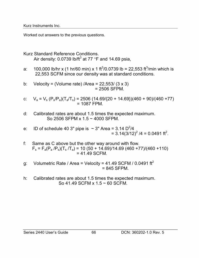
Kurz Instruments Inc.
Series 2440 User’s Guide 66 DCN: 360202-1.0 Rev. 5
Worked out answers to the previous questions.
Kurz Standard Reference Conditions. Air density: 0.0739 lb/ft3 at 77 °F and 14.69 psia,
a: 100,000 lb/hr x (1 hr/60 min) x 1 ft3/0.0739 lb = 22,553 ft3/min which is22,553 SCFM since our density was at standard conditions.
b: Velocity = (Volume rate) /Area = 22,553/ (3 x 3) = 2506 SFPM.
c: Va = Vs (Ps/Pa)(Ta/Ts) = 2506 (14.69/{20 + 14.69})(460 + 90)/(460 +77) = 1087 FPM.
d: Calibrated rates are about 1.5 times the expected maximum. So 2506 SFPM x 1.5 ~ 4000 SFPM.
e: ID of schedule 40 3" pipe is ~ 3" Area = 3.14 D2/4 = 3.14(3/12)2 /4 = 0.0491 ft2.
f: Same as C above but the other way around with flow.Fs = Fa(Pa /Ps)(Ts /Ta) = 10 (50 + 14.69)/14.69 (460 +77)/(460 +110)
= 41.49 SCFM.
g: Volumetric Rate / Area = Velocity = 41.49 SCFM / 0.0491 ft2 = 845 SFPM.
h: Calibrated rates are about 1.5 times the expected maximum.So 41.49 SCFM x 1.5 ~ 60 SCFM.

Kurz Instruments Inc.
Series 2440 User’s Guide 67 DCN: 360202-1.0 Rev. 5
Appendix BProduct Approvals
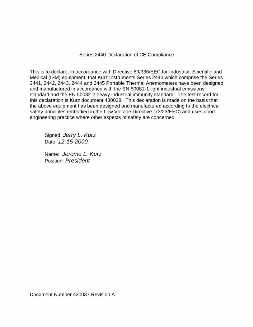
Document Number 430037 Revision A
Series 2440 Declaration of CE Compliance
This is to declare, in accordance with Directive 89/336/EEC for Industrial, Scientific andMedical (ISM) equipment; that Kurz Instruments Series 2440 which comprise the Series2441, 2442, 2443, 2444 and 2445 Portable Thermal Anemometers have been designedand manufactured in accordance with the EN 50081-1 light industrial emissionsstandard and the EN 50082-2 heavy industrial immunity standard. The test record forthis declaration is Kurz document 430038. This declaration is made on the basis thatthe above equipment has been designed and manufactured according to the electricalsafety principles embodied in the Low Voltage Directive (73/23/EEC) and uses goodengineering practice where other aspects of safety are concerned.
Signed: Jerry L. Kurz Date: 12-15-2000
Name: Jerome L. KurzPosition: President

Kurz Instruments Inc.
Series 2440 User’s Guide 68 DCN: 360202-1.0 Rev. 5
Appendix CMFTCOMMC Installation andOperation
451017 MFTCOMMC Installation and Operation Guide

Kurz Instruments Inc.
MFTCOMMC Version 1.41
Installation and Operation
Kurz Instruments Inc.
MFTCOMMC VERSION 1.41 Guide 2 DCN: 451017-1.41.PDF
Introduction
MFTCOMMC is a Series MFT and PTA configuration upload/download program forWindows with text translators to make printable files. MFTCOMMC version 1.41 willmake printable files of MFT 1.0x, 1.1x, 1.2x and 1.3x and PTA 1.0x configuration files.
Installation
System Requirements: An RS-232 port and Windows NT,98 or 95 operating systems.
With each MFT and PTA unit is a 3 ½ “ floppy disk that contains the program filesfor MFTCOMMC and the original factory configuration of the unit.
To install this program you simply execute the 451017-1.41.exe self extractinginstallation program. You will be prompted with a message telling you what version isbeing installed. Next you get a WinZip dialog box to choose a destination directory forthe installation. The default is C:\Kurz\MFTCOMMC. Once you have selected thedestination directory, chose the Unzip button. It will say “X files unzippedsuccessfully”. Then you Close the WinZip utility. Lastly, make a Desktop shortcut orStart menu shortcut to the program MFTCOMMC.exe in the new folder. Now yourready to go.
Menus
The first time you run MFTCOMMC it must be configured for the serial port and baudrate you will use for communicating to the MFT and PTA unit. This is typically theCOM1 serial port and 9600 baud. You click on the menu Communication Port thenselect the port and baud rate followed by ok.
Note: None of the Help buttons are implemented in this version of the program. TheFile menu items New, Open, Save and Save As are also not implemented.
The main menus are:
File Update Communication Port Help
Kurz Instruments Inc.
MFTCOMM VERSION 1.41 Guide 3 DCN: 451017-1.41.PDF
The File menu is used to select:
Upload (Transfer a file from a MFT or PTA unit to the PC)Download (Transfer a configuration file from the PC to the MFT
or PTA unit.)Create Printable File (convert a configuration file to ASCII text and write it
to the PC disk drive.)View Look at a configuration file on screen. (Launches
Wordpad)Print Prints the last file converted to ASCII to your default
printer.
The Update menu is used at the factory to load flow calibration data to a configurationfile and is not discussed here.
The Communications Port menu is used to select the baud rate and port describedunder installation above.
The Help menu is not implemented yet but does tell you the version of the programunder the About button.
Setup for Upload/Download
1. You first connect a straight through RS-232 cable between the PCs COM port andthe DB-9 RS-232 port on the user I/O board of the Series MFT or PTA unit. 2. The MFT or PTA must be on and in executive mode. You can not be in Display orProgram mode for this to work correctly. 3. Start the MFTCOMMC program and make sure its serial port is correctlyconfigured, see installation above.
Saving an MFT configuration on your PC
1. First setup the hardware and software described above. 2. To save an MFT or PTA configuration you select File then Upload followed by typinga file name in the name field of the Save As file pop-up window.. To see the other filesin the directory you will have to change the Save as type to All Files (*.*). This type hasno impact on the files except what you see in the dialog box. If you want to save theconfiguration file with the name “Greatflowmeter” then you just type this in with orwithout an extension. Select the directory where you want to place the file. Theconfiguration file is only about 1.8 kbytes.
Kurz Instruments Inc.
MFTCOMM VERSION 1.41 Guide 4 DCN: 451017-1.41.PDF
3. During the file transfer, a dialog box which says “Wait.... UPLOADING MFTCONFIGURATION”. If you do not have the MFT or PTA unit plugged into the RS-232serial port of the user I/O board or the power is off, this message will stay on the screen. You may have to terminate the program to correct the error and start over. (Control-Alt-Del then select the task)
Viewing or Printing the Configuration File
Once you have a configuration file you can then:
1. Select the option Create Printable File under the File menu. After a printable file iscreated the menu options for View and Print under File show up. Both the view andprint options use WordPad to view or print the file. You close WordPad when doneviewing. 2. To print you select Print under the File menu. When printing, WordPad will bepulled up then closed automatically after sending to the default system printer.
Figure C1 shows a typical configuration file. The length of this printable file dependson the number of data points, temperature data sets and velocity correction factorsetc.
Downloading a Configuration from the PC to the MFT or PTA Unit
1. Configure the hardware and software as described above. 2. Transferring a configuration from the PC to the MFT or PTA unit is started bychoosing Download under the File menu. 3. You select the file to be transferred with the file Open menu. 4. Chose the file type as All to see your files. 5. Chose the proper directory then click Open after you have selected the file. Thescreen will then pull up a dialog screen which says “Wait... DOWNLOADING THEMFT CONFIGURATION.” This takes less than10 seconds. If it hangs up, check yourcable connections, MFT or PTA power and is it in Executive mode? You must terminatethe program if it gets stuck. (Control-Alt- Del then select the task)
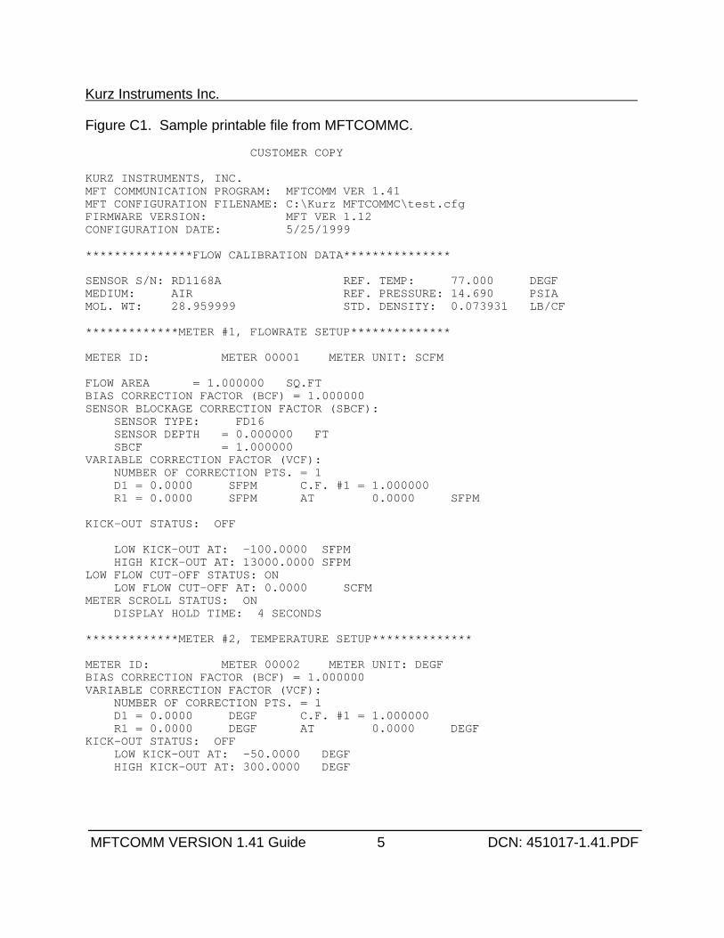
Kurz Instruments Inc.
MFTCOMM VERSION 1.41 Guide 5 DCN: 451017-1.41.PDF
Figure C1. Sample printable file from MFTCOMMC.
CUSTOMER COPY
KURZ INSTRUMENTS, INC.MFT COMMUNICATION PROGRAM: MFTCOMM VER 1.41MFT CONFIGURATION FILENAME: C:\Kurz MFTCOMMC\test.cfgFIRMWARE VERSION: MFT VER 1.12CONFIGURATION DATE: 5/25/1999
***************FLOW CALIBRATION DATA***************
SENSOR S/N: RD1168A REF. TEMP: 77.000 DEGFMEDIUM: AIR REF. PRESSURE: 14.690 PSIAMOL. WT: 28.959999 STD. DENSITY: 0.073931 LB/CF
*************METER #1, FLOWRATE SETUP**************
METER ID: METER 00001 METER UNIT: SCFM
FLOW AREA = 1.000000 SQ.FTBIAS CORRECTION FACTOR (BCF) = 1.000000 SENSOR BLOCKAGE CORRECTION FACTOR (SBCF): SENSOR TYPE: FD16 SENSOR DEPTH = 0.000000 FT SBCF = 1.000000 VARIABLE CORRECTION FACTOR (VCF): NUMBER OF CORRECTION PTS. = 1 D1 = 0.0000 SFPM C.F. #1 = 1.000000 R1 = 0.0000 SFPM AT 0.0000 SFPM
KICK-OUT STATUS: OFF
LOW KICK-OUT AT: -100.0000 SFPM HIGH KICK-OUT AT: 13000.0000 SFPMLOW FLOW CUT-OFF STATUS: ON LOW FLOW CUT-OFF AT: 0.0000 SCFMMETER SCROLL STATUS: ON DISPLAY HOLD TIME: 4 SECONDS *************METER #2, TEMPERATURE SETUP**************
METER ID: METER 00002 METER UNIT: DEGFBIAS CORRECTION FACTOR (BCF) = 1.000000 VARIABLE CORRECTION FACTOR (VCF): NUMBER OF CORRECTION PTS. = 1 D1 = 0.0000 DEGF C.F. #1 = 1.000000 R1 = 0.0000 DEGF AT 0.0000 DEGFKICK-OUT STATUS: OFF LOW KICK-OUT AT: -50.0000 DEGF HIGH KICK-OUT AT: 300.0000 DEGF
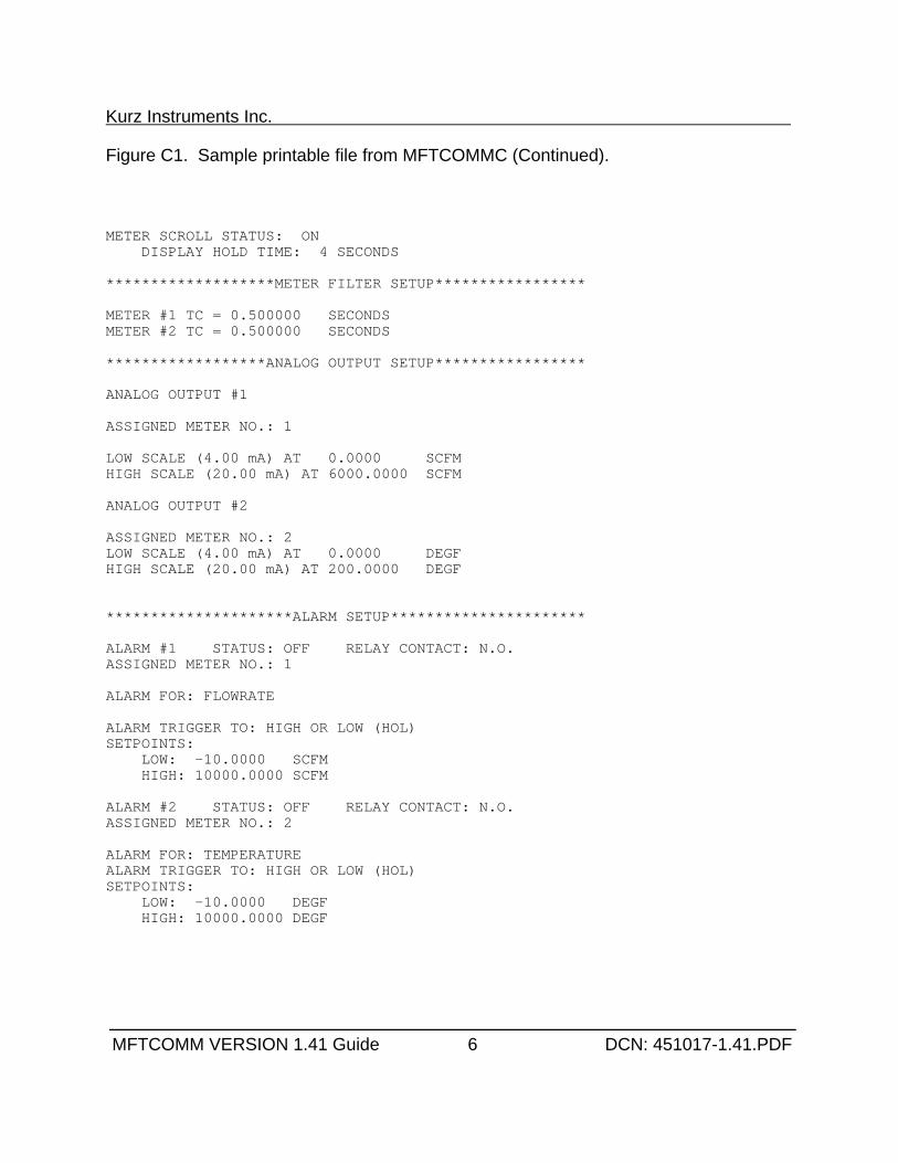
Kurz Instruments Inc.
MFTCOMM VERSION 1.41 Guide 6 DCN: 451017-1.41.PDF
Figure C1. Sample printable file from MFTCOMMC (Continued).
METER SCROLL STATUS: ON DISPLAY HOLD TIME: 4 SECONDS *******************METER FILTER SETUP***************** METER #1 TC = 0.500000 SECONDSMETER #2 TC = 0.500000 SECONDS ******************ANALOG OUTPUT SETUP***************** ANALOG OUTPUT #1
ASSIGNED METER NO.: 1
LOW SCALE (4.00 mA) AT 0.0000 SCFMHIGH SCALE (20.00 mA) AT 6000.0000 SCFM
ANALOG OUTPUT #2
ASSIGNED METER NO.: 2LOW SCALE (4.00 mA) AT 0.0000 DEGFHIGH SCALE (20.00 mA) AT 200.0000 DEGF
*********************ALARM SETUP********************** ALARM #1 STATUS: OFF RELAY CONTACT: N.O.ASSIGNED METER NO.: 1
ALARM FOR: FLOWRATE
ALARM TRIGGER TO: HIGH OR LOW (HOL)SETPOINTS: LOW: -10.0000 SCFM HIGH: 10000.0000 SCFM ALARM #2 STATUS: OFF RELAY CONTACT: N.O.ASSIGNED METER NO.: 2
ALARM FOR: TEMPERATUREALARM TRIGGER TO: HIGH OR LOW (HOL)SETPOINTS: LOW: -10.0000 DEGF HIGH: 10000.0000 DEGF
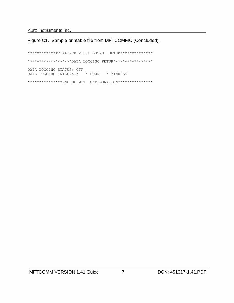
Kurz Instruments Inc.
MFTCOMM VERSION 1.41 Guide 7 DCN: 451017-1.41.PDF
Figure C1. Sample printable file from MFTCOMMC (Concluded).
************TOTALIZER PULSE OUTPUT SETUP**************
*******************DATA LOGGING SETUP*****************
DATA LOGGING STATUS: OFFDATA LOGGING INTERVAL: 5 HOURS 5 MINUTES
***************END OF MFT CONFIGURATION***************
Kurz Instruments Inc.
Series 2440 User’s Guide 69 DCN: 360202-1.0 Rev. 5
Appendix DField Wiring Diagrams
342035 Series 2440 field wiring diagram (4 sheets)
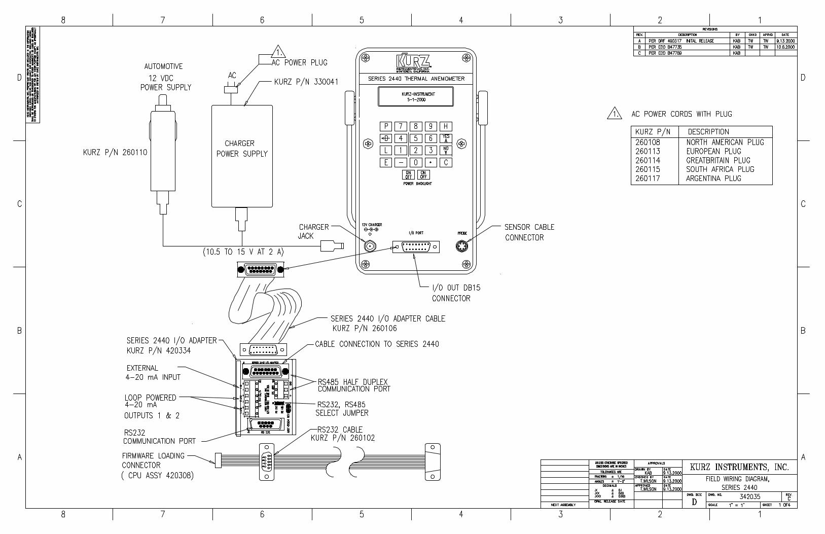
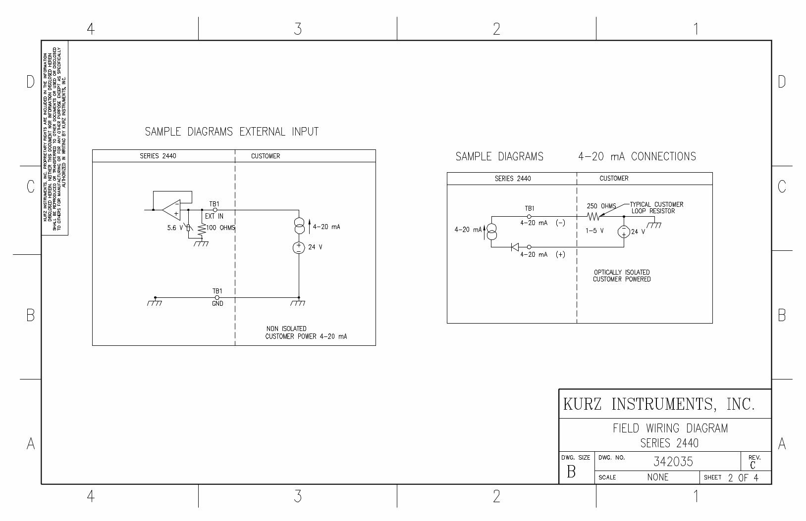
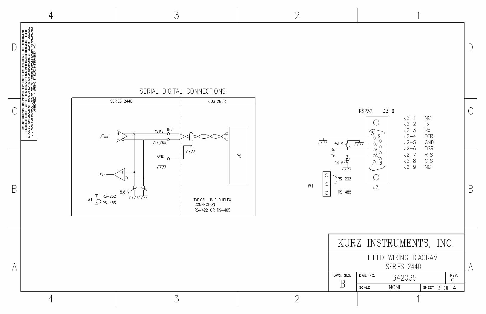
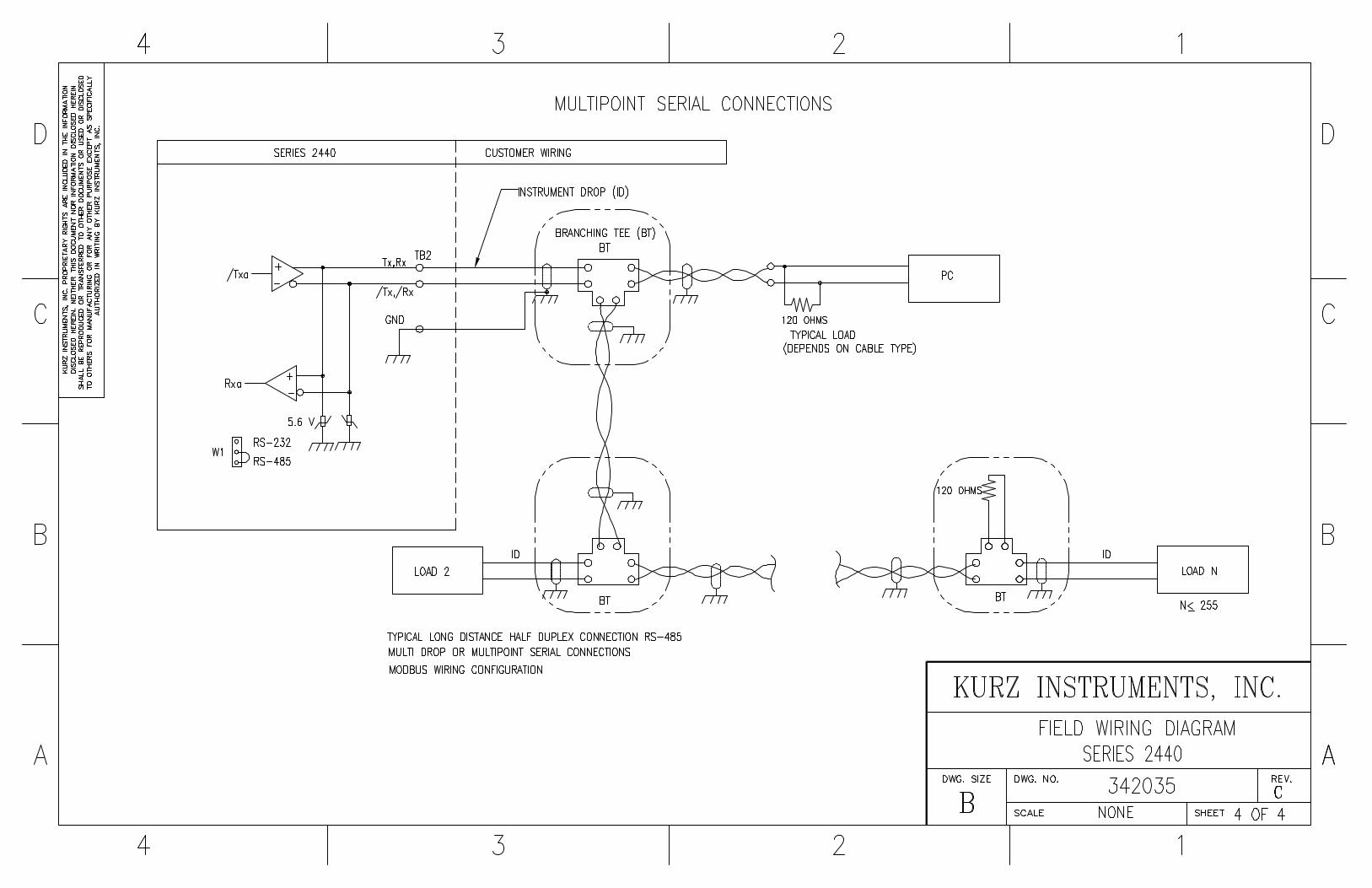

Kurz Instruments Inc.
Series 2440 User’s Guide 70 DCN: 360202-1.0 Rev. 5
Appendix EMenu State Diagrams
342034 PTA menu state diagram (12 sheets)
Pages 9, 10 and 11 have been removed which are for the Factory access code.
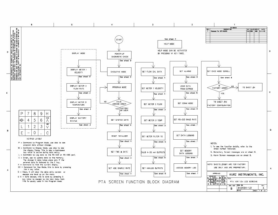
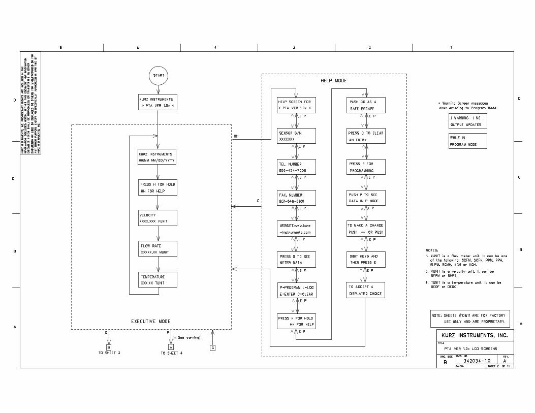
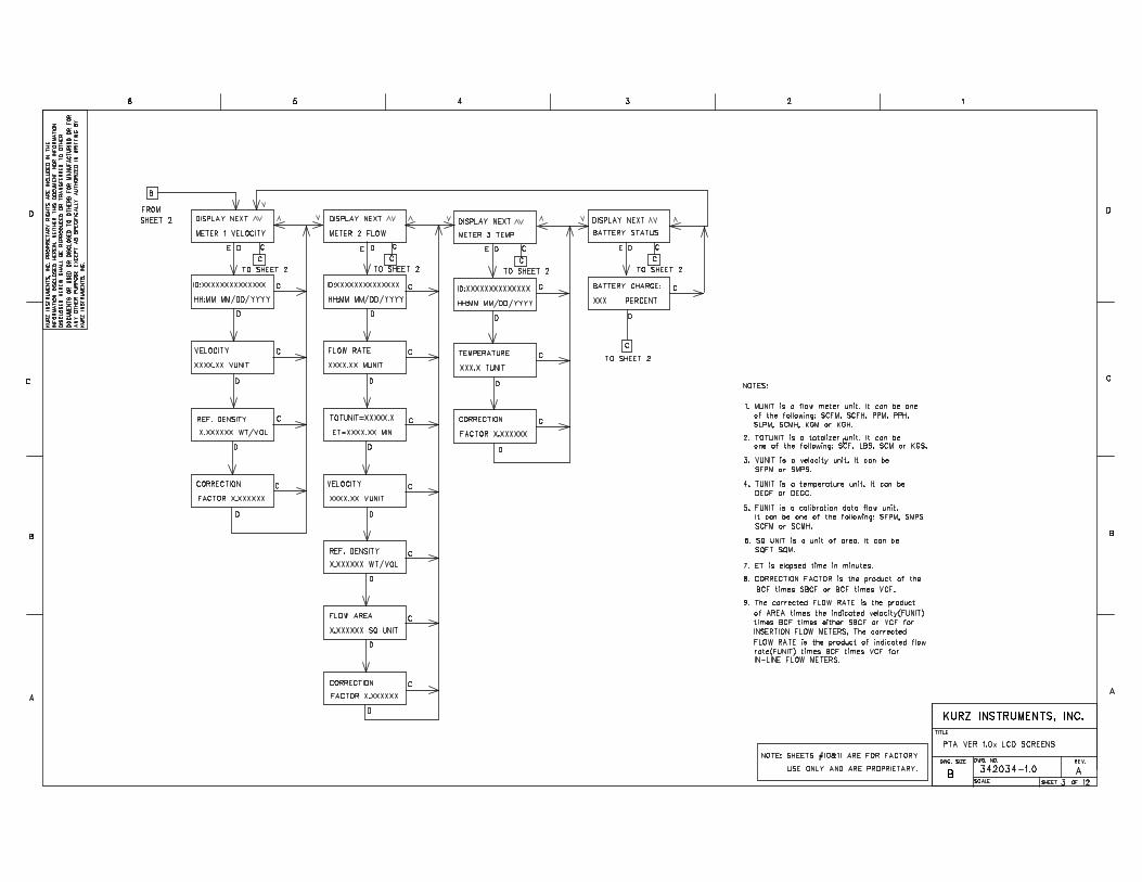
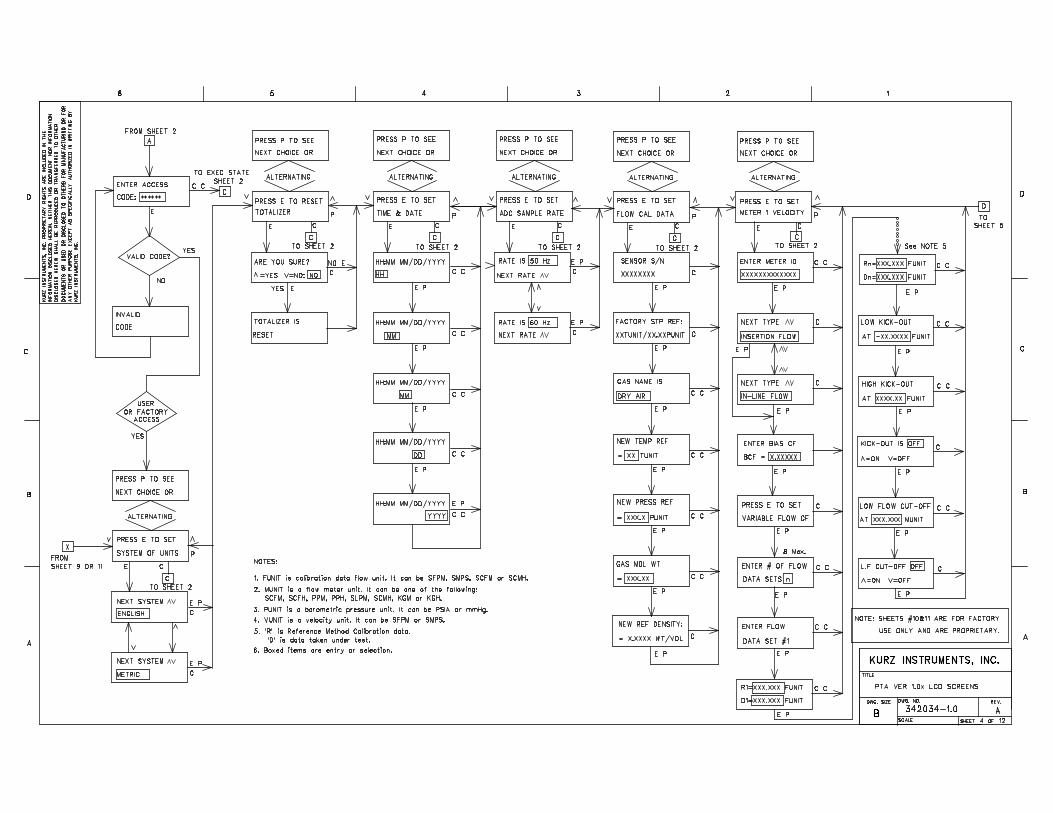
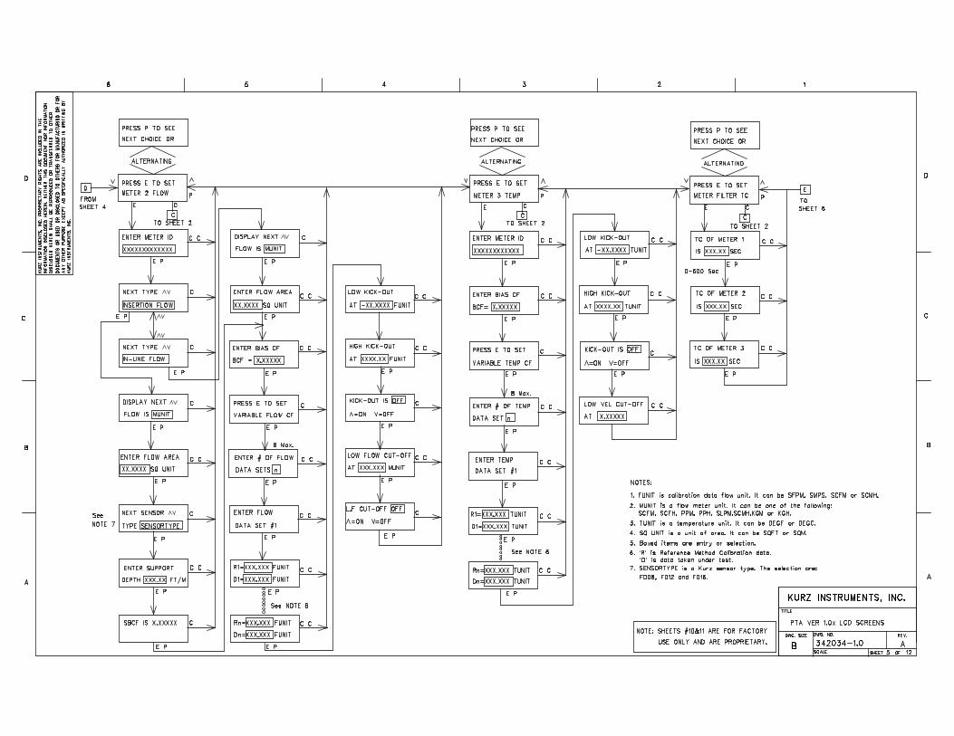
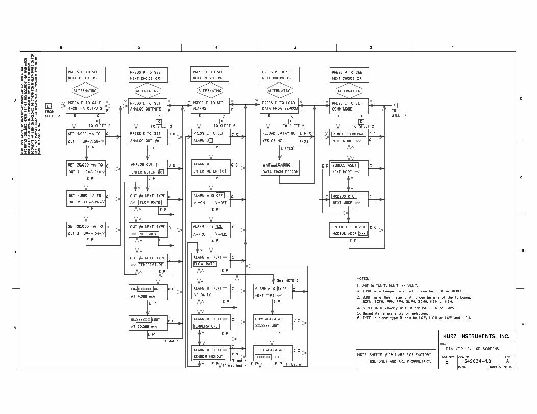
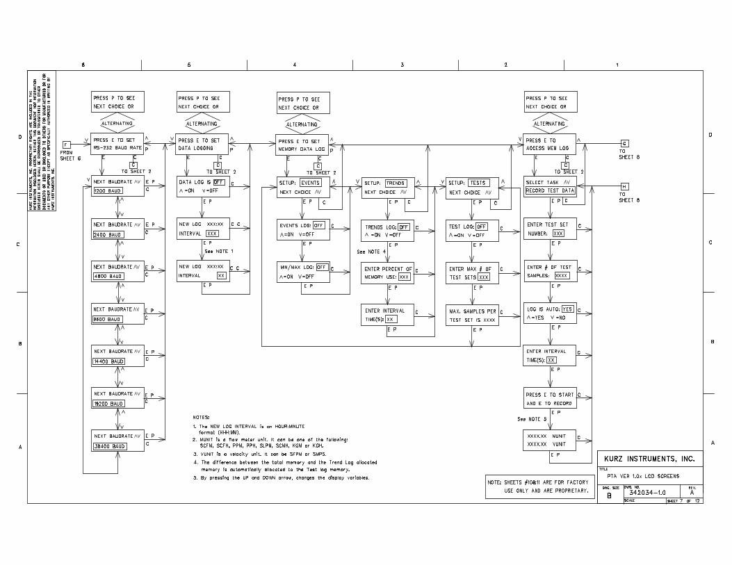
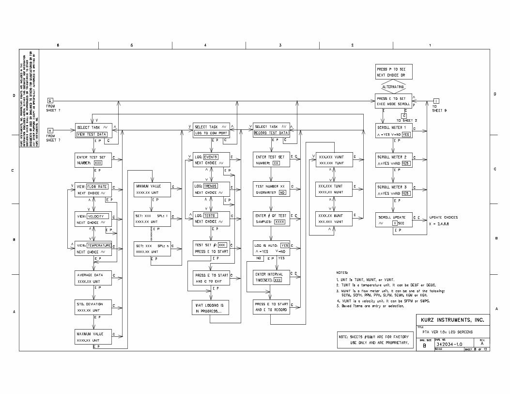
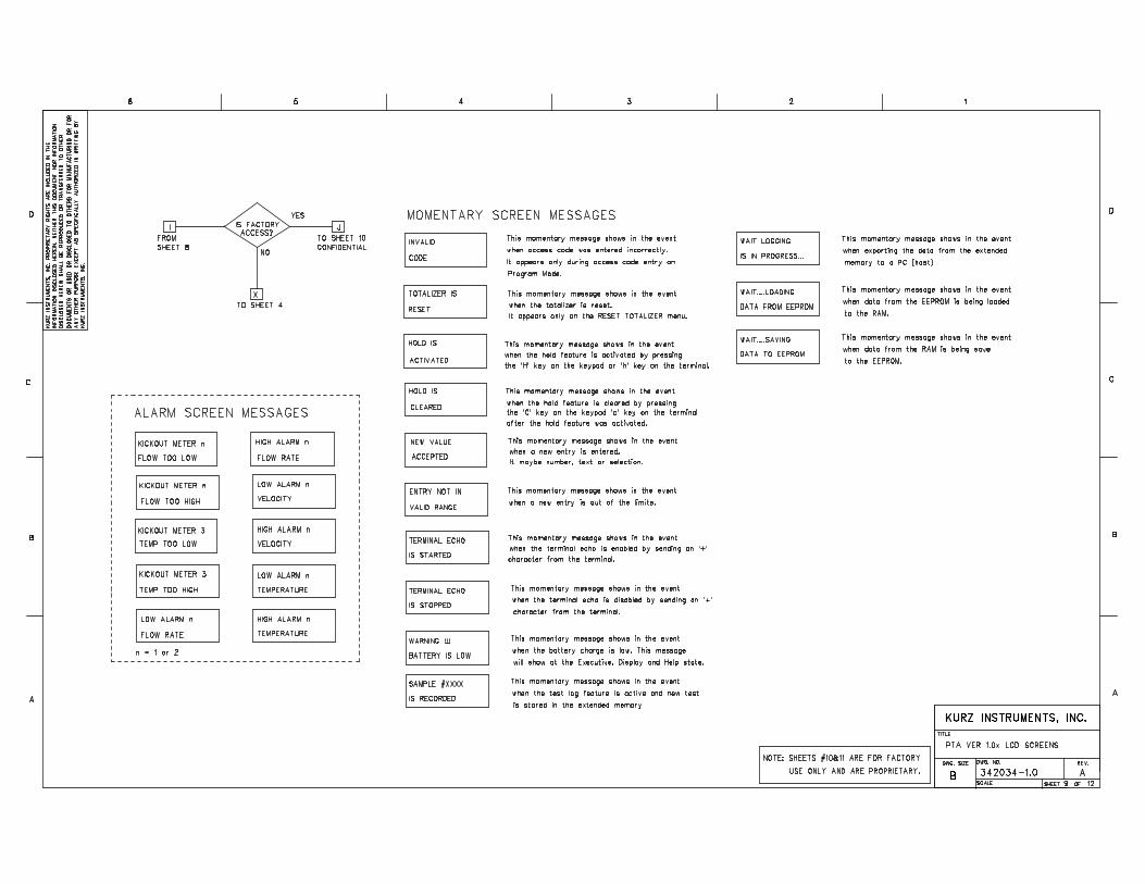
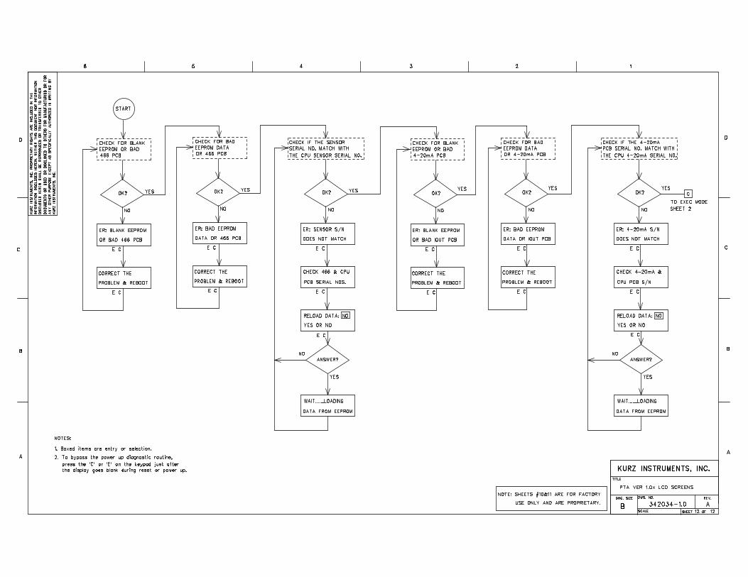
Kurz Instruments Inc.
Series 2440 User’s Guide 71 DCN: 360202-1.0 Rev. 5
Appendix FSignal Flow Diagram
342036 Series 2440 signal flow diagram
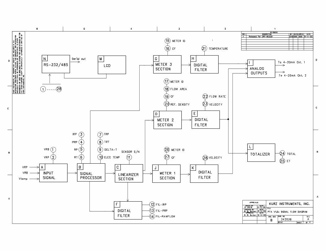
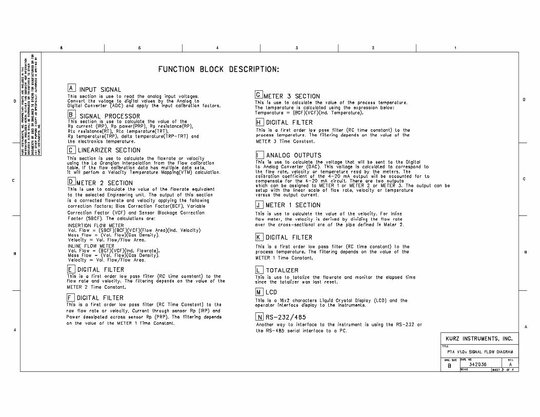
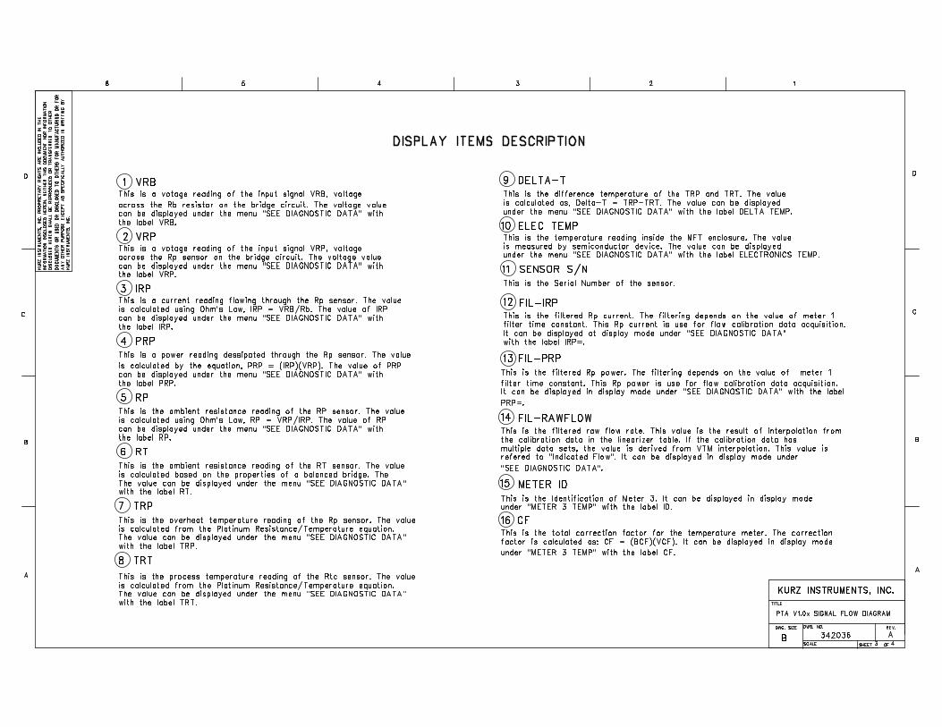
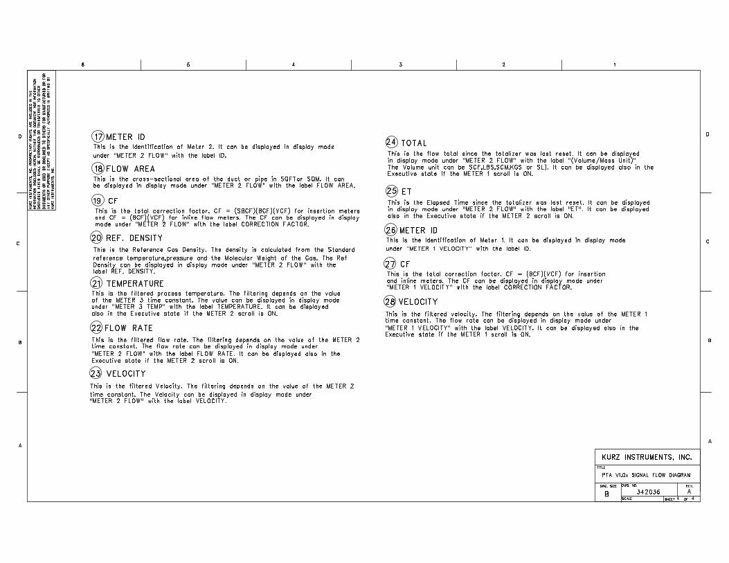
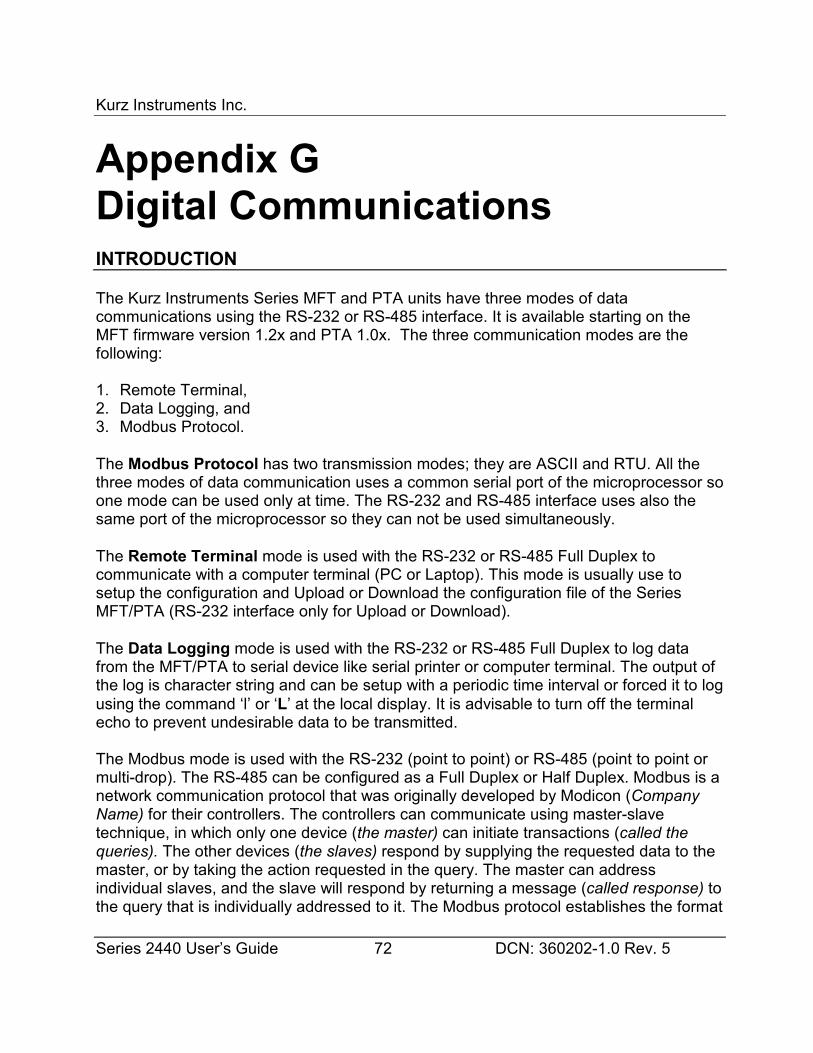
Kurz Instruments Inc.
Series 2440 User’s Guide 72 DCN: 360202-1.0 Rev. 5
Appendix GDigital CommunicationsINTRODUCTION
The Kurz Instruments Series MFT and PTA units have three modes of datacommunications using the RS-232 or RS-485 interface. It is available starting on theMFT firmware version 1.2x and PTA 1.0x. The three communication modes are thefollowing:
1. Remote Terminal,2. Data Logging, and3. Modbus Protocol.
The Modbus Protocol has two transmission modes; they are ASCII and RTU. All thethree modes of data communication uses a common serial port of the microprocessor soone mode can be used only at time. The RS-232 and RS-485 interface uses also thesame port of the microprocessor so they can not be used simultaneously.
The Remote Terminal mode is used with the RS-232 or RS-485 Full Duplex tocommunicate with a computer terminal (PC or Laptop). This mode is usually use tosetup the configuration and Upload or Download the configuration file of the SeriesMFT/PTA (RS-232 interface only for Upload or Download).
The Data Logging mode is used with the RS-232 or RS-485 Full Duplex to log datafrom the MFT/PTA to serial device like serial printer or computer terminal. The output ofthe log is character string and can be setup with a periodic time interval or forced it to logusing the command ‘l’ or ‘L’ at the local display. It is advisable to turn off the terminalecho to prevent undesirable data to be transmitted.
The Modbus mode is used with the RS-232 (point to point) or RS-485 (point to point ormulti-drop). The RS-485 can be configured as a Full Duplex or Half Duplex. Modbus is anetwork communication protocol that was originally developed by Modicon (CompanyName) for their controllers. The controllers can communicate using master-slavetechnique, in which only one device (the master) can initiate transactions (called thequeries). The other devices (the slaves) respond by supplying the requested data to themaster, or by taking the action requested in the query. The master can addressindividual slaves, and the slave will respond by returning a message (called response) tothe query that is individually addressed to it. The Modbus protocol establishes the format
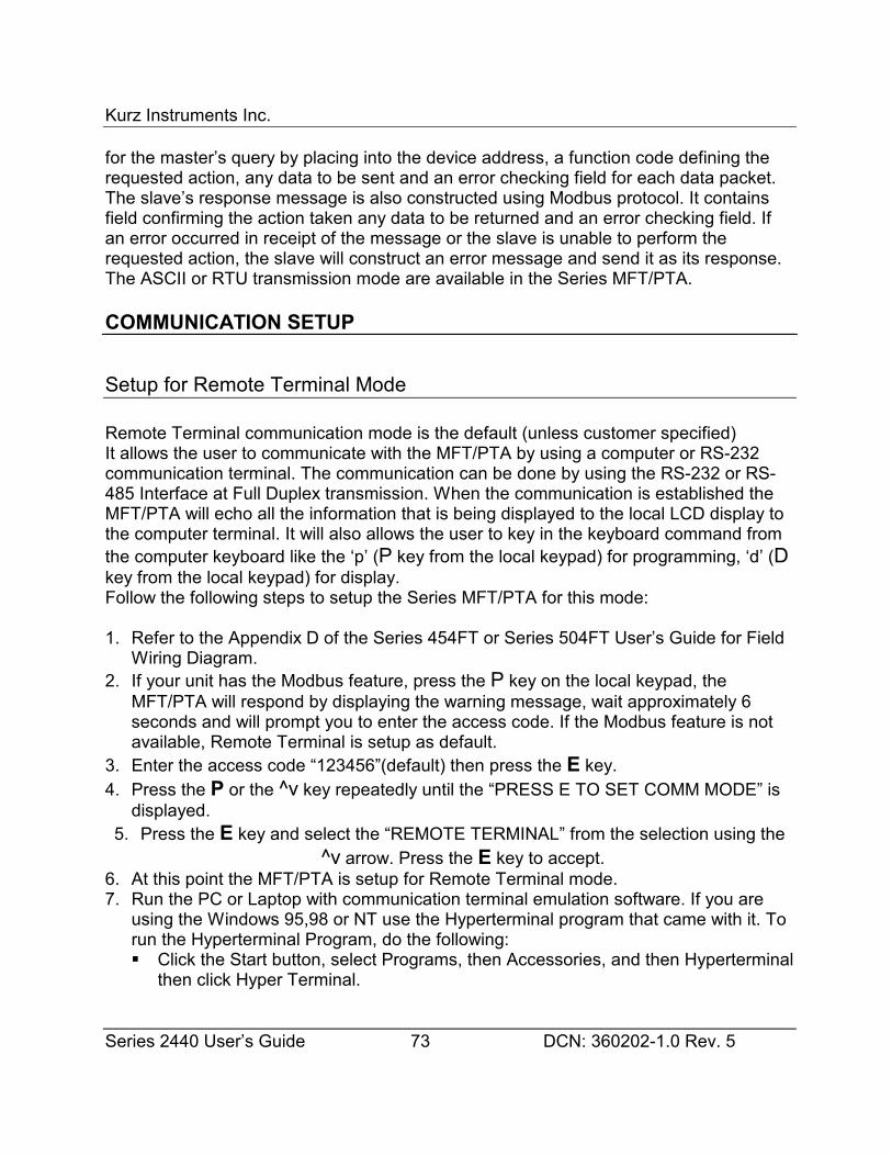
Kurz Instruments Inc.
Series 2440 User’s Guide 73 DCN: 360202-1.0 Rev. 5
for the master’s query by placing into the device address, a function code defining therequested action, any data to be sent and an error checking field for each data packet.The slave’s response message is also constructed using Modbus protocol. It containsfield confirming the action taken any data to be returned and an error checking field. Ifan error occurred in receipt of the message or the slave is unable to perform therequested action, the slave will construct an error message and send it as its response.The ASCII or RTU transmission mode are available in the Series MFT/PTA.
COMMUNICATION SETUP
Setup for Remote Terminal Mode
Remote Terminal communication mode is the default (unless customer specified)It allows the user to communicate with the MFT/PTA by using a computer or RS-232communication terminal. The communication can be done by using the RS-232 or RS-485 Interface at Full Duplex transmission. When the communication is established theMFT/PTA will echo all the information that is being displayed to the local LCD display tothe computer terminal. It will also allows the user to key in the keyboard command fromthe computer keyboard like the ‘p’ (P key from the local keypad) for programming, ‘d’ (Dkey from the local keypad) for display.Follow the following steps to setup the Series MFT/PTA for this mode:
1. Refer to the Appendix D of the Series 454FT or Series 504FT User’s Guide for FieldWiring Diagram.
2. If your unit has the Modbus feature, press the P key on the local keypad, theMFT/PTA will respond by displaying the warning message, wait approximately 6seconds and will prompt you to enter the access code. If the Modbus feature is notavailable, Remote Terminal is setup as default.
3. Enter the access code “123456”(default) then press the E key.4. Press the P or the ^v key repeatedly until the “PRESS E TO SET COMM MODE” is
displayed.5. Press the E key and select the “REMOTE TERMINAL” from the selection using the
^v arrow. Press the E key to accept.6. At this point the MFT/PTA is setup for Remote Terminal mode.7. Run the PC or Laptop with communication terminal emulation software. If you are
using the Windows 95,98 or NT use the Hyperterminal program that came with it. Torun the Hyperterminal Program, do the following:� Click the Start button, select Programs, then Accessories, and then Hyperterminal
then click Hyper Terminal.
Kurz Instruments Inc.
Series 2440 User’s Guide 74 DCN: 360202-1.0 Rev. 5
� The program will run and pop up a window called “Connection Description”.� Enter a name (filename) and select an icon and click the OK button.� Another window will pop up called “Connect To”. Since the RS-232 port will be
used, select the box labeled “Connect using” and select COM1 or COM2 orCOM3 depending what communication port you are using then click the OKbutton.
� Another window will pop up called “Port Setting”. This is where you configure theRS-232 communication parameters.
� At the box labeled “Bits per second” select the proper baud rate configured in theSeries MFT/PTA, the default Series MFT/PTA baud rate is 9600 baud. If theMFT/PTA unit baud rate set at 9600 baud, select the 9600 baud in this box. Atthe “Data bits” box select 8, the “Parity” box select None, “Stop bits” box select 1and the “Flow control” box to None. Click the OK button when everything wasselected. At this point you should see a data on the program window receivedfrom the Series MFT/PTA.
� If no data is being received, press the ‘+’ key on the keyboard to command theSeries MFT/PTA to start echoing data. Save the connections for future use byclicking the File menu then Save.
Setup for Data Logging Mode
The Data logging mode is an extension feature of the Remote Terminal mode. Whenthis feature is available, the Series MFT/PTA allows the user to setup a periodic loginterval for the Series MFT/PTA to log data to a serial device like computer terminal orserial printer. In addition, the Series MFT/PTA can be force to log the MFT/PTA data byusing the ‘l’ (‘L’ key from the local keypad) command. The format of the data is a textstring consists of three lines terminated with the RETURN character (ASCII 13). The firstline is the time and date when the data was logged. The second line is Flow Meter(Meter #1) data consist of the following:
• The Meter Number.• The Meter Identification (Meter ID).• The flow rate and the engineering unit.• The Total flow and the unit.
The third line is the Temperature Meter (Meter #2) data consist of the following:• The Meter Number.• The Meter Identification (Meter ID).• The Temperature and the engineering unit.
Example data from the Series MFT/PTA log function or the ‘l’ command:
Kurz Instruments Inc.
Series 2440 User’s Guide 75 DCN: 360202-1.0 Rev. 5
Host issues lMFT/PTA reply 13:58:23 2/09/99
#1 FT456 0.23459 SCFM 1.238999e3 SCF#2 TT456 125.71 DEGF
Follow the following steps to setup the Series MFT/PTA for this mode:
1. Follow the setup for the Remote Terminal Mode (See section “Setup forRemote Terminal Mode). The Serial communication must be establishedbefore the data logging will work.
2. Send the ‘l’ character from the computer terminal or the L from the localkeypad. If the communication is working properly, the Series MFT/PTA shouldreply a text string like the example above. In order to have a clean unclutteredreply on the computer terminal display or serial printer, turn off the terminalecho. Sending the ‘+’ command will toggle the status of the terminal echo.
3. The periodic log interval can be setup in the program mode. Press P on thelocal keypad or send ‘p’ if you are using the computer terminal. The SeriesMFT/PTA will respond by displaying the warning message. Afterapproximately 6 seconds, the Series MFT/PTA will ask for the access code,enter the access code “123456”(factory default). Press the ^v arrowrepeatedly until you reach the menu “SET DATA LOGGING”. Press E on thelocal keypad or the return from the computer terminal.
4. Turn ON the data log and enter the data log time interval, enter the minutesthen the seconds.
5. Press C to exit to the executive mode.
Setup for Modbus Mode
The Series MFT/PTA can be configured for Modbus protocol communications.The Modbus mode of transmission can be selected either Modbus ASCII or ModbusRTU. The Series MFT/PTA must be used only as slave devices and they will work only ifthey are used with a master device. RS-232 or RS-485 Interface can be used tocommunicate with the Series MFT/PTA. The RS-232 can be use only as a Full Duplexfor point to point communication (Master and Slave). The RS-485 can be use either FullDuplex or Half Duplex and can be point to point or multi-drop (1 Master and 1 or moreSlaves) operation. Each slave devices must have its unique device address within thenetwork. The individual slave device address can be assigned in the range of 1-247.
Kurz Instruments Inc.
Series 2440 User’s Guide 76 DCN: 360202-1.0 Rev. 5
WARNING
Do not connect the Series MFT/PTA to the Modbus Network until it is properlyconfigured.
The MFT/PTA Series may be setup for Modbus communications if the option isavailable. Follow the following instructions to setup for Modbus operation:
1. Press the P key on the local keypad, the MFT/PTA will respond bydisplaying the warning message, wait approximately 6 seconds and will prompt you to enter the access code.
2. Enter the access code “123456”(default) then press the E key on the local keypad.
3. Press the P or the ^v key repeatedly until the “PRESS E TO SET COMM MODE” isdisplayed.
4. Press the E key and select the “MODBUS ASCII” or “MODBUS RTU” from theselection. Press the E key to accept. The communication parameters for the ModbusASCII are the following:
7 DatabitsNo Parity2 Stop bits
The baud rate may be selected under the menu “SET RS-232 BAUD RATE”. Thefactory default is 9600 baud.
The communication parameters for the Modbus RTU are the following:
8 DatabitsNo Parity1 Stop bit
The baud rate may be selected under the menu “SET RS-232 BAUD RATE”. Thefactory default is 9600 baud.
Kurz Instruments Inc.
Series 2440 User’s Guide 77 DCN: 360202-1.0 Rev. 5
1. The next display is used to assign the slave address of the Series MFT/PTA. Enterthe slave address (valid range 1-247) and press the E key. If the Series MFT/PTAwill be used in a multi-drop network, make sure that you assigned an address uniqueto all of the devices connected to the network. The default address set in the factoryis 1.
2. Press the C key to return to the executive mode.3. Refer to Appendix D of the Series 2440 field wiring diagrams.
SERIES MFT/PTA MODBUS COMMAND AND REGISTERS
The Modbus function codes are expressed in byte length (8 bits), example functioncode:
01 = Read Coil Status02 = Read Input Status03 = Read Holding Registers
The Series MFT/PTA only support the function code 03, Read the Holding register of theSeries MFT/PTA. A register is defined as a 16-bit storage of data. This means that aninteger number will occupy one register, floating point number will occupy two registersand two ASCII characters in one register.
These registers are mapped to the internal variables of the Series MFT/PTA and areavailable to access by specifying the equivalent Modbus register. The table belowdefined the Modbus register of the Series MFT/PA and description of the internalvariables:
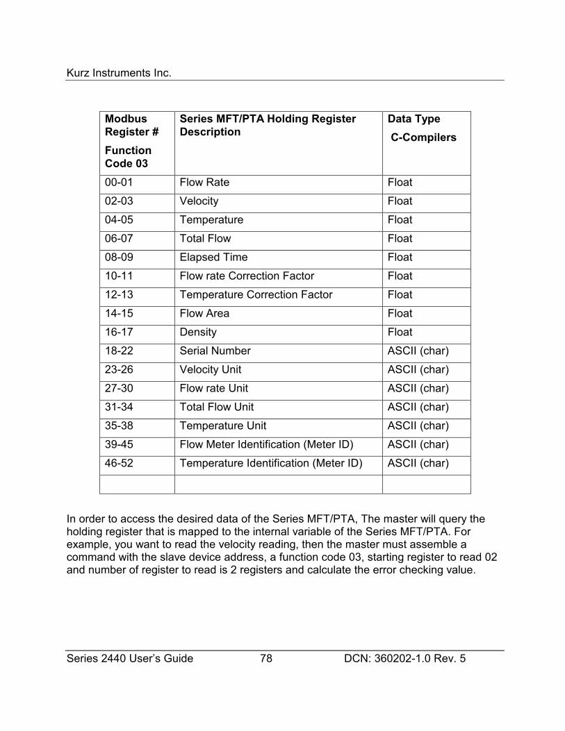
Kurz Instruments Inc.
Series 2440 User’s Guide 78 DCN: 360202-1.0 Rev. 5
ModbusRegister #FunctionCode 03
Series MFT/PTA Holding RegisterDescription
Data Type C-Compilers
00-01 Flow Rate Float02-03 Velocity Float04-05 Temperature Float06-07 Total Flow Float08-09 Elapsed Time Float10-11 Flow rate Correction Factor Float12-13 Temperature Correction Factor Float14-15 Flow Area Float16-17 Density Float18-22 Serial Number ASCII (char)23-26 Velocity Unit ASCII (char)27-30 Flow rate Unit ASCII (char)31-34 Total Flow Unit ASCII (char)35-38 Temperature Unit ASCII (char)39-45 Flow Meter Identification (Meter ID) ASCII (char)46-52 Temperature Identification (Meter ID) ASCII (char)
In order to access the desired data of the Series MFT/PTA, The master will query theholding register that is mapped to the internal variable of the Series MFT/PTA. Forexample, you want to read the velocity reading, then the master must assemble acommand with the slave device address, a function code 03, starting register to read 02and number of register to read is 2 registers and calculate the error checking value.
Kurz Instruments Inc.
Series 2440 User’s Guide 79 DCN: 360202-1.0 Rev. 5
Appendix HVelocity Traverse FieldCalibrationsLD-3802 In-Situ Field Calibration (11 sheets)
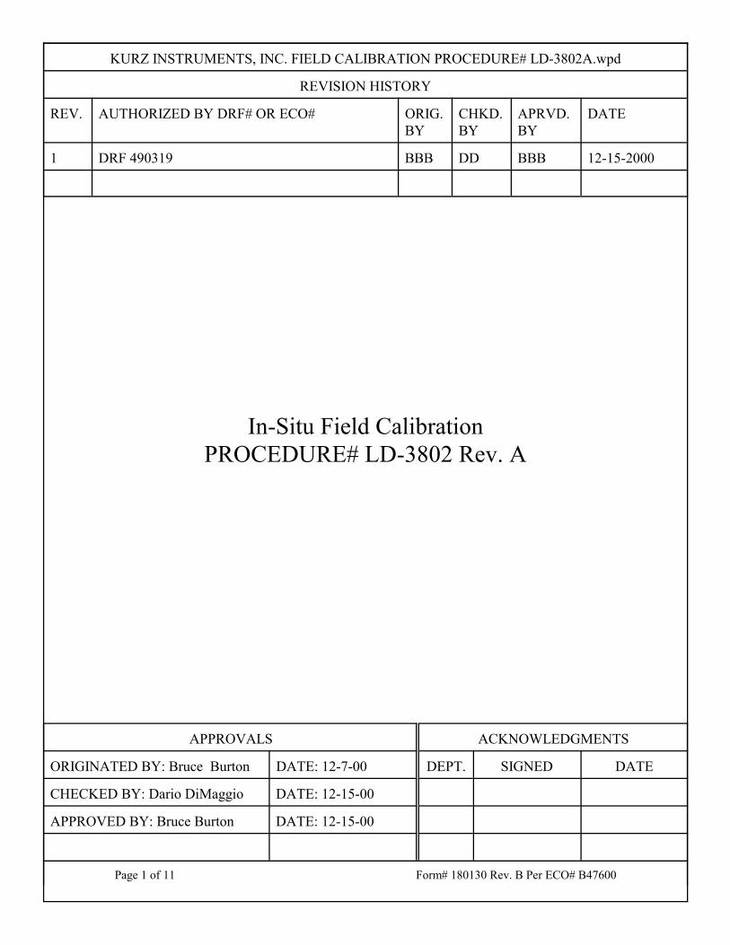
KURZ INSTRUMENTS, INC. FIELD CALIBRATION PROCEDURE# LD-3802A.wpd
REVISION HISTORY
REV. AUTHORIZED BY DRF# OR ECO# ORIG.BY
CHKD.BY
APRVD.BY
DATE
1 DRF 490319 BBB DD BBB 12-15-2000
APPROVALS ACKNOWLEDGMENTS
ORIGINATED BY: Bruce Burton DATE: 12-7-00 DEPT. SIGNED DATE
CHECKED BY: Dario DiMaggio DATE: 12-15-00
APPROVED BY: Bruce Burton DATE: 12-15-00
Page 1 of 11 Form# 180130 Rev. B Per ECO# B47600
In-Situ Field CalibrationPROCEDURE# LD-3802 Rev. A
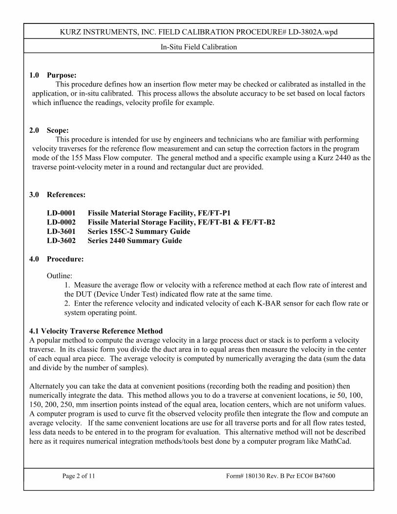
KURZ INSTRUMENTS, INC. FIELD CALIBRATION PROCEDURE# LD-3802A.wpd
In-Situ Field Calibration
Page 2 of 11 Form# 180130 Rev. B Per ECO# B47600
1.0 Purpose:This procedure defines how an insertion flow meter may be checked or calibrated as installed in the
application, or in-situ calibrated. This process allows the absolute accuracy to be set based on local factorswhich influence the readings, velocity profile for example.
2.0 Scope:This procedure is intended for use by engineers and technicians who are familiar with performing
velocity traverses for the reference flow measurement and can setup the correction factors in the programmode of the 155 Mass Flow computer. The general method and a specific example using a Kurz 2440 as thetraverse point-velocity meter in a round and rectangular duct are provided.
3.0 References:
LD-0001 Fissile Material Storage Facility, FE/FT-P1LD-0002 Fissile Material Storage Facility, FE/FT-B1 & FE/FT-B2LD-3601 Series 155C-2 Summary GuideLD-3602 Series 2440 Summary Guide
4.0 Procedure:
Outline: 1. Measure the average flow or velocity with a reference method at each flow rate of interest andthe DUT (Device Under Test) indicated flow rate at the same time.2. Enter the reference velocity and indicated velocity of each K-BAR sensor for each flow rate orsystem operating point.
4.1 Velocity Traverse Reference MethodA popular method to compute the average velocity in a large process duct or stack is to perform a velocitytraverse. In its classic form you divide the duct area in to equal areas then measure the velocity in the centerof each equal area piece. The average velocity is computed by numerically averaging the data (sum the dataand divide by the number of samples).
Alternately you can take the data at convenient positions (recording both the reading and position) thennumerically integrate the data. This method allows you to do a traverse at convenient locations, ie 50, 100,150, 200, 250, mm insertion points instead of the equal area, location centers, which are not uniform values. A computer program is used to curve fit the observed velocity profile then integrate the flow and compute anaverage velocity. If the same convenient locations are use for all traverse ports and for all flow rates tested,less data needs to be entered in to the program for evaluation. This alternative method will not be describedhere as it requires numerical integration methods/tools best done by a computer program like MathCad.
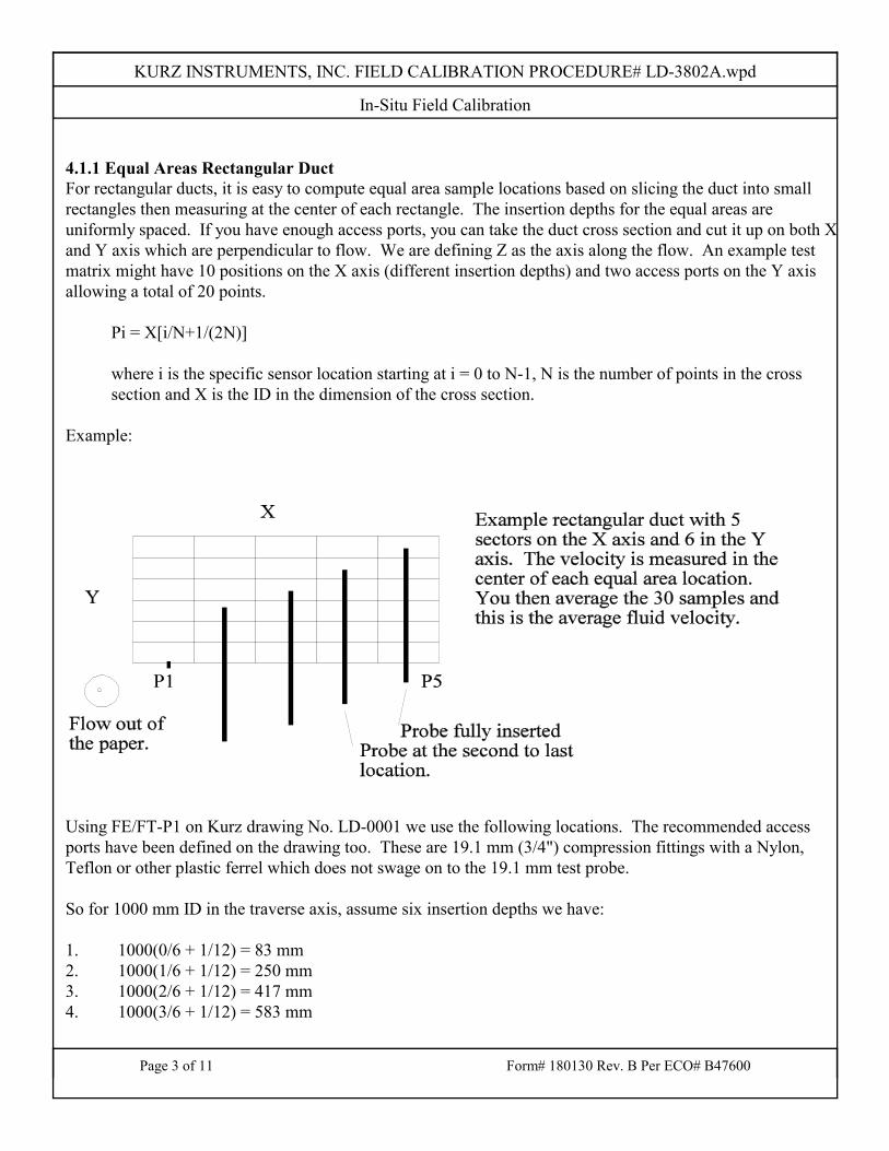
KURZ INSTRUMENTS, INC. FIELD CALIBRATION PROCEDURE# LD-3802A.wpd
In-Situ Field Calibration
Page 3 of 11 Form# 180130 Rev. B Per ECO# B47600
4.1.1 Equal Areas Rectangular DuctFor rectangular ducts, it is easy to compute equal area sample locations based on slicing the duct into smallrectangles then measuring at the center of each rectangle. The insertion depths for the equal areas areuniformly spaced. If you have enough access ports, you can take the duct cross section and cut it up on both Xand Y axis which are perpendicular to flow. We are defining Z as the axis along the flow. An example testmatrix might have 10 positions on the X axis (different insertion depths) and two access ports on the Y axisallowing a total of 20 points.
Pi = X[i/N+1/(2N)]
where i is the specific sensor location starting at i = 0 to N-1, N is the number of points in the crosssection and X is the ID in the dimension of the cross section.
Example:
Using FE/FT-P1 on Kurz drawing No. LD-0001 we use the following locations. The recommended accessports have been defined on the drawing too. These are 19.1 mm (3/4") compression fittings with a Nylon,Teflon or other plastic ferrel which does not swage on to the 19.1 mm test probe.
So for 1000 mm ID in the traverse axis, assume six insertion depths we have:
1. 1000(0/6 + 1/12) = 83 mm2. 1000(1/6 + 1/12) = 250 mm3. 1000(2/6 + 1/12) = 417 mm4. 1000(3/6 + 1/12) = 583 mm
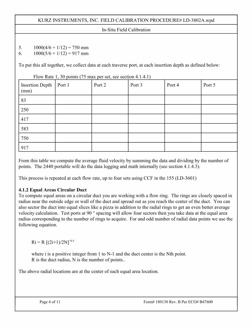
KURZ INSTRUMENTS, INC. FIELD CALIBRATION PROCEDURE# LD-3802A.wpd
In-Situ Field Calibration
Page 4 of 11 Form# 180130 Rev. B Per ECO# B47600
5. 1000(4/6 + 1/12) = 750 mm6. 1000(5/6 + 1/12) = 917 mm
To put this all together, we collect data at each traverse port, at each insertion depth as defined below:
Flow Rate 1, 30 points (75 max per set, see section 4.1.4.1)
Insertion Depth(mm)
Port 1 Port 2 Port 3 Port 4 Port 5
83
250
417
583
750
917
From this table we compute the average fluid velocity by summing the data and dividing by the number ofpoints. The 2440 portable will do the data logging and math internally (see section 4.1.4.3).
This process is repeated at each flow rate, up to four sets using CCF in the 155 (LD-3601)
4.1.2 Equal Areas Circular DuctTo compute equal areas on a circular duct you are working with a flow ring. The rings are closely spaced inradius near the outside edge or wall of the duct and spread out as you reach the center of the duct. You canalso sector the duct into equal slices like a pizza in addition to the radial rings to get an even better averagevelocity calculation. Test ports at 90 ° spacing will allow four sectors then you take data at the equal arearadius corresponding to the number of rings to acquire. For and odd number of radial data points we use thefollowing equation.
Ri = R [(2i+1)/2N]^0.5
where i is a positive integer from 1 to N-1 and the duct center is the Nth point.R is the duct radius, N is the number of points..
The above radial locations are at the center of each equal area location.
KURZ INSTRUMENTS, INC. FIELD CALIBRATION PROCEDURE# LD-3802A.wpd
In-Situ Field Calibration
Page 5 of 11 Form# 180130 Rev. B Per ECO# B47600
Example: For a 1400 mm ID duct (FE/FT-B1 and FE/FE-B2, on Kurz drawing No. LD-0002) we wouldmeasure at the following locations. Using five equal area locations on each of four sectors or traverse portsmakes 20 total measurement points. The following radial locations are needed for equal area points.
1. Duct Center, 0 mm radius1. 700[(2+1)/10]^0.5 = 383 mm2. 700[(4+1)/10]^0.5 = 495 mm3. 700[(6+1)/10]^0.5 = 586 mm4. 700[(8+1)/10]^0.5 = 664 mm
The corresponding traverse insertion depth is then the duct radius less the radial location or:
Insertion depth = R-Ri
1. 700 - 0 = 700 mm insertion depth2. 700 - 383 = 317 mm insertion depth3. 700 - 495 = 205 mm insertion depth4. 700 - 586 = 114 mm insertion depth5. 700 - 664 = 36 mm insertion depth
KURZ INSTRUMENTS, INC. FIELD CALIBRATION PROCEDURE# LD-3802A.wpd
In-Situ Field Calibration
Page 6 of 11 Form# 180130 Rev. B Per ECO# B47600
A data chart like defined for the rectangular duct (4.1.1) can be made and used. Again, you would repeat thewhole process for each flow rate or system operating point up to a maximum of four flow rates.
4.1.3 Velocity Traverse Data AcquisitionOnce the number and location of the equal area center points are known they will be used to position the probeat the center of each area.
During the traverse procedure, the process flow rate must be at equilibrium so the computed average from thetravers is for the same flow rates on all test ports. The traverse average velocity is obtained using either therectangular duct or circular duct methods described above. The indicated average velocity on the device beingcalibrated (the 155C-2) is recorded by logging each sensor’s velocity while the traverse is performed. See LD-3601 on the 155 which describes how to setup the log interval and record it on a computer or printer.
4.1.3.1 Traverse Probe Blockage: For small ducts, the sensor and probe support blockage must be accounted for. As the probe is inserted deeperin the duct, it blocks off more of the flow causing an increase in local velocity due to the smaller duct area.. Acorrection factor can be defined to convert the observed reading to that which an ideal (no blockage sensor)reading would have been. To first order, a sensor blockage correction factor (SBCF) can be defined asfollows.
SBCF (d) =(Area -d*w) / Area
where Area is based on the ID, d is the insertion depth and w is the probe diameter.
True velocity = Indicated * SBCF (d)
Example: For a circular duct whose diameter is 1000 mm, and a 19.05 mm (3/4") diameter probeinserted half way, this CF = (π x 5002 - 19.05 x 500 )/ π x 5002 = 98.79 % or 1.2 % error if ignored. Since this only represents a small part of the total number of samples which have even less blockage,this factor can be ignored for this example, the estimated error is less than 0.25%. The increase inaccuracy is not worth the extra computational trouble.
4.1.4 Velocity Probe type, Series 2440A thermal anemometer which reads standard velocity corrected to reference conditions used at Kurz is veryconvenient (0 °C, 760 mmHg). The readings are logged, then directly averaged using the equal area method.
To use the insertion depth information in the above example you must note the center of the velocity probesensing element. The center of the sensing location on the sensor is 20 mm from the probe end. This startpoint is Y mm beyond the compression fitting’s outside edge (site specific depends on duct wall thickness and
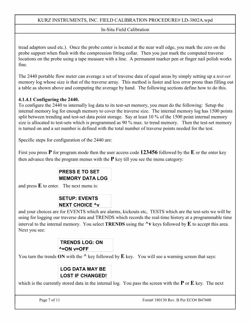
KURZ INSTRUMENTS, INC. FIELD CALIBRATION PROCEDURE# LD-3802A.wpd
In-Situ Field Calibration
Page 7 of 11 Form# 180130 Rev. B Per ECO# B47600
tread adaptors used etc.). Once the probe center is located at the near wall edge, you mark the zero on theprobe support when flush with the compression fitting collar. Then you just mark the computed traverselocations on the probe using a tape measure with a line. A permanent marker pen or finger nail polish worksfine.
The 2440 portable flow meter can average a set of traverse data of equal areas by simply setting up a test-setmemory log whose size is that of the traverse array. This method is faster and less error prone than filling outa table as shown above and computing the average by hand. The following sections define how to do this.
4.1.4.1 Configuring the 2440.To configure the 2440 to internally log data to its test-set memory, you must do the following: Setup theinternal memory log for enough memory to cover the traverse size. The internal memory log has 1500 pointssplit between trending and test-set data point storage. Say at least 10 % of the 1500 point internal memorysize is allocated to test-sets which is programmed as 90 % max. to trend memory. Then the test-set memoryis turned on and a set number is defined with the total number of traverse points needed for the test.
Specific steps for configuration of the 2440 are:
First you press P for program mode then the user access code 123456 followed by the E or the enter keythen advance thru the program menus with the P key till you see the menu category:
PRESS E TO SETMEMORY DATA LOG
and press E to enter. The next menu is:
SETUP: EVENTS NEXT CHOICE ^v
and your choices are for EVENTS which are alarms, kickouts etc, TESTS which are the test-sets we will beusing for logging our traverse data and TRENDS which records the real-time history at a programmable timeinterval to the internal memory. You select TRENDS using the ^v keys followed by E to accept this area. Next you see:
TRENDS LOG: ON^=ON v=OFF
You turn the trends ON with the ^ key followed by E key. You will see a warning screen that says:
LOG DATA MAY BE LOST IF CHANGED!
which is the currently stored data in the internal log. You pass the screen with the P or E key. The next
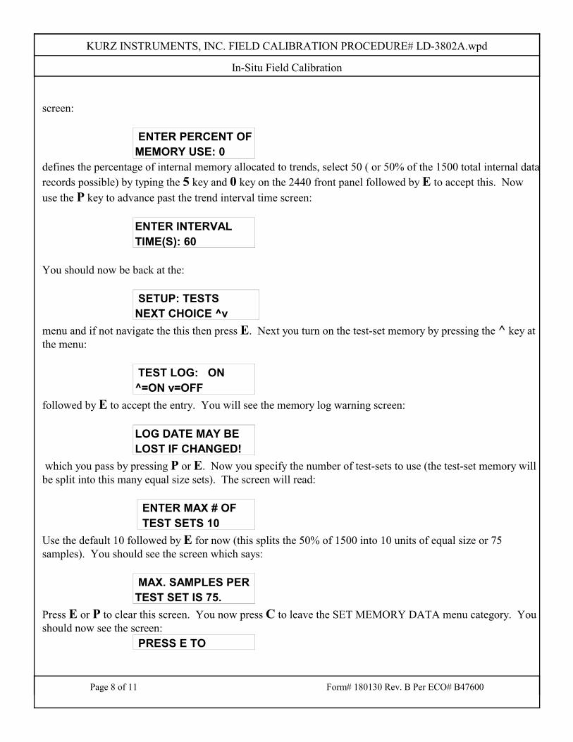
KURZ INSTRUMENTS, INC. FIELD CALIBRATION PROCEDURE# LD-3802A.wpd
In-Situ Field Calibration
Page 8 of 11 Form# 180130 Rev. B Per ECO# B47600
screen:
ENTER PERCENT OFMEMORY USE: 0
defines the percentage of internal memory allocated to trends, select 50 ( or 50% of the 1500 total internal datarecords possible) by typing the 5 key and 0 key on the 2440 front panel followed by E to accept this. Nowuse the P key to advance past the trend interval time screen:
ENTER INTERVALTIME(S): 60
You should now be back at the:
SETUP: TESTSNEXT CHOICE ^v
menu and if not navigate the this then press E. Next you turn on the test-set memory by pressing the ^ key atthe menu:
TEST LOG: ON ^=ON v=OFF
followed by E to accept the entry. You will see the memory log warning screen:
LOG DATE MAY BELOST IF CHANGED!
which you pass by pressing P or E. Now you specify the number of test-sets to use (the test-set memory willbe split into this many equal size sets). The screen will read:
ENTER MAX # OF TEST SETS 10
Use the default 10 followed by E for now (this splits the 50% of 1500 into 10 units of equal size or 75samples). You should see the screen which says:
MAX. SAMPLES PERTEST SET IS 75.
Press E or P to clear this screen. You now press C to leave the SET MEMORY DATA menu category. Youshould now see the screen:
PRESS E TO
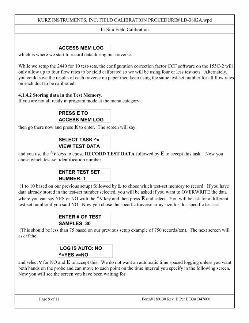
KURZ INSTRUMENTS, INC. FIELD CALIBRATION PROCEDURE# LD-3802A.wpd
In-Situ Field Calibration
Page 9 of 11 Form# 180130 Rev. B Per ECO# B47600
ACCESS MEM LOG which is where we start to record data during our traverse.
While we setup the 2440 for 10 test-sets, the configuration correction factor CCF software on the 155C-2 willonly allow up to four flow rates to be field calibrated so we will be using four or less test-sets. Alternately,you could save the results of each traverse on paper then keep using the same test-set number for all flow rateson each duct to be calibrated.
4.1.4.2 Storing data in the Test Memory.If you are not all ready in program mode at the menu category:
PRESS E TO ACCESS MEM LOG
then go there now and press E to enter. The screen will say:
SELECT TASK ^vVIEW TEST DATA
and you use the ^v keys to chose RECORD TEST DATA followed by E to accept this task. Now youchose which test-set identification number
ENTER TEST SETNUMBER: 1
(1 to 10 based on our previous setup) followed by E to chose which test-set memory to record. If you havedata already stored in the test-set number selected, you will be asked if you want to OVERWRITE the datawhere you can say YES or NO with the ^v key and then press E and select. You will be ask for a differenttest-set number if you said NO. Now you chose the specific traverse array size for this specific test-set
ENTER # OF TESTSAMPLES: 30
(This should be less than 75 based on our previous setup example of 750 records/ten). The next screen willask if the:
LOG IS AUTO: NO^=YES v=NO
and select v for NO and E to accept this. We do not want an automatic time spaced logging unless you wantboth hands on the probe and can move to each point on the time interval you specify in the following screen. Now you will see the screen you have been waiting for:
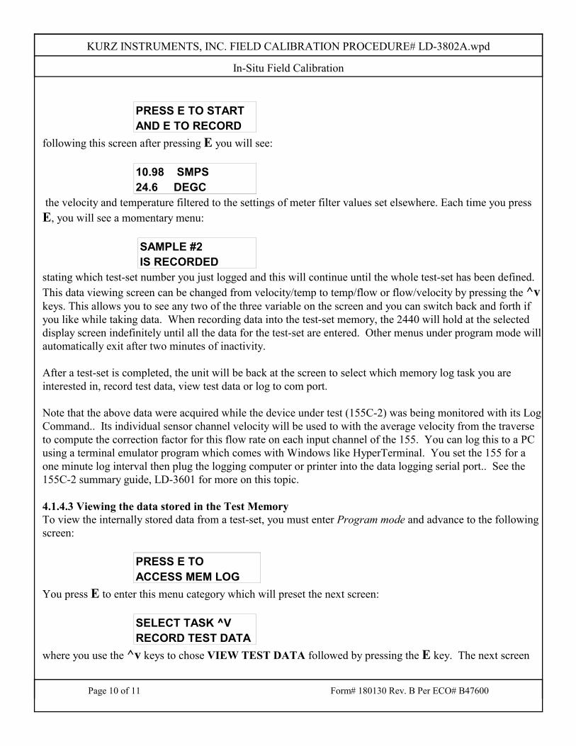
KURZ INSTRUMENTS, INC. FIELD CALIBRATION PROCEDURE# LD-3802A.wpd
In-Situ Field Calibration
Page 10 of 11 Form# 180130 Rev. B Per ECO# B47600
PRESS E TO STARTAND E TO RECORD
following this screen after pressing E you will see:
10.98 SMPS24.6 DEGC
the velocity and temperature filtered to the settings of meter filter values set elsewhere. Each time you pressE, you will see a momentary menu:
SAMPLE #2IS RECORDED
stating which test-set number you just logged and this will continue until the whole test-set has been defined.This data viewing screen can be changed from velocity/temp to temp/flow or flow/velocity by pressing the ^vkeys. This allows you to see any two of the three variable on the screen and you can switch back and forth ifyou like while taking data. When recording data into the test-set memory, the 2440 will hold at the selecteddisplay screen indefinitely until all the data for the test-set are entered. Other menus under program mode willautomatically exit after two minutes of inactivity.
After a test-set is completed, the unit will be back at the screen to select which memory log task you areinterested in, record test data, view test data or log to com port.
Note that the above data were acquired while the device under test (155C-2) was being monitored with its LogCommand.. Its individual sensor channel velocity will be used to with the average velocity from the traverseto compute the correction factor for this flow rate on each input channel of the 155. You can log this to a PCusing a terminal emulator program which comes with Windows like HyperTerminal. You set the 155 for aone minute log interval then plug the logging computer or printer into the data logging serial port.. See the155C-2 summary guide, LD-3601 for more on this topic.
4.1.4.3 Viewing the data stored in the Test MemoryTo view the internally stored data from a test-set, you must enter Program mode and advance to the followingscreen:
PRESS E TO ACCESS MEM LOG
You press E to enter this menu category which will preset the next screen:
SELECT TASK ^VRECORD TEST DATA
where you use the ^v keys to chose VIEW TEST DATA followed by pressing the E key. The next screen
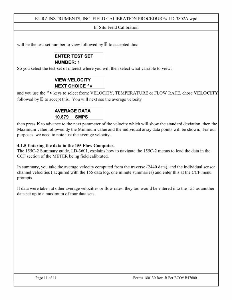
KURZ INSTRUMENTS, INC. FIELD CALIBRATION PROCEDURE# LD-3802A.wpd
In-Situ Field Calibration
Page 11 of 11 Form# 180130 Rev. B Per ECO# B47600
will be the test-set number to view followed by E to accepted this:
ENTER TEST SETNUMBER: 1
So you select the test-set of interest where you will then select what variable to view:
VIEW:VELOCITYNEXT CHOICE ^v
and you use the ^v keys to select from: VELOCITY, TEMPERATURE or FLOW RATE, chose VELOCITYfollowed by E to accept this. You will next see the average velocity
AVERAGE DATA10.879 SMPS
then press E to advance to the next parameter of the velocity which will show the standard deviation, then theMaximum value followed dy the Minimum value and the individual array data points will be shown. For ourpurposes, we need to note just the average velocity.
4.1.5 Entering the data in the 155 Flow Computer.The 155C-2 Summary guide, LD-3601, explains how to navigate the 155C-2 menus to load the data in theCCF section of the METER being field calibrated.
In summary, you take the average velocity computed from the traverse (2440 data), and the individual sensorchannel velocities ( acquired with the 155 data log, one minute summaries) and enter this at the CCF menuprompts.
If data were taken at other average velocities or flow rates, they too would be entered into the 155 as anotherdata set up to a maximum of four data sets.