kwim series - klimaireklimaire.com/media/support/kwim/kwim-series-service-manual.pdf · kwim series...
TRANSCRIPT
P
Multi zone Indoor
I N D O O
Model Numbers:
KWIM09-H2KWIM12-H2KWIM18-H2
WARNING
Installation MUST conform with local building codes or, in the absence of local codes, with the National Electrical Code
NFPA70/ANSI C1-1993 or current edition and Canadian Electrical Code Part1 CSA C.22.1.
The information contained in the manual is intended for use by a qualified service technician familiar with safety
procedures and equipped with the proper tools and test instruments
Installation or repairs made by unqualified persons can result in hazards to you and others.
Failure to carefully read and follow all instructions in this manual can result in equipment malfunction, property damage,
personal injury and/or death.
Table of Contents
1. Precaution
2. Product Description And Label
3. Dimension of indoor unit
4. Operation Characteristics
5. Electronic function
6. Wiring Diagrams
7. Trouble Shooting
8. Disassembly instructions
9. Exploded view
KWIM Series Service Manual

CONTENTS
1. Precaution ........................................................................................................................................... 2
1.1 Safety Precaution ........................................................................................................................ 2
1.2 Warning ...................................................................................................................................... 2
2. Product Description And Label ............................................................................................................. 6
3. Dimension of indoor unit ..................................................................................................................... 7
4. Operation Characteristics ..................................................................................................................... 8
5. Electronic Function .............................................................................................................................. 8
5.1 Abbreviation ...................................................................................................................................... 8
5.2Main Protection .................................................................................................................................. 8
5.3 Operation Modes and Functions ........................................................................................................ 8
6. Wiring Diagrams..................................................................................................................................13
7. Troubleshooting ..................................................................................................................................14
7.1 Display Function ................................................................................................................................14
7.2Indoor Unit Error Display ....................................................................................................................15
7.3 Outdoor Unit Error Display ................................................................................................................16
7.4 Diagnosis and Solution ......................................................................................................................18
7.5 Trouble Criterion Of Main Parts. ........................................................................................................89
8. Disassembly Instructions ...................................................................................................................100
9. Exploded View ..................................................................................................................................105

2
1. Precaution
1.1 Safety Precaution
To prevent injury to the user or
other people and property damage,
the following instructions must be
followed.
Incorrect operation due to ignoring
instruction will cause harm or
damage.
Before service unit, be sure to read
this service manual at first.
1.2 Warning
Installation
Do not use a defective or
underrated circuit breaker. Use this
appliance on a dedicated circuit.
There is risk of fire or electric
shock.
For electrical work, contact the
dealer, seller, a qualified electrician,
or an Authorized service center.
Do not disassemble or repair the
product, there is risk of fire or
electric shock.
Always ground the product.
Install the panel and the cover of
control box securely.
Always install a dedicated circuit
and breaker.
Improper wiring or installation may
cause fore or electric shock.
Use the correctly rated breaker of
fuse.
Do not modify or extend the power
cable.
The unit should be installed,
removed, or reinstalled by a
certified HVAC professional who is
locally licensed to handle this
product.
Be cautious when unpacking and
installing the product, sharp edges
could cause injury, be especially
careful of the edges of the
cabinet and the fins on the
condenser and evaporator.
For installation, always contact the
dealer or an authorized service
center.
Do not install the product on a
defective installation stand as this
may cause and accident, injury, or
damage to the product.
Be sure the installation area does
not deteriorate with age. If the
base collapses, the air conditioner
could fall with it, causing property
damage, product failure and
personal injury.
3
Take care to ensure that the power
cable could not be disconnected or
damaged during operation.
Do not place anything on the
power cable.
Do not unplug the power supply
plug during operation.
Do not touch (operation) the
product with wet hands.
Do not place a heater or other
appliance near the power cable.
Do not allow water to run into
electric parts. It may cause fire,
failure of the product, or electric
shock.
Do not store or use flammable gas
or combustible near the product.
Ensure that the condensing unit
has proper ventilation. Do not use
the product in a tightly closed
space for a long time.
If smoke is detected during the
operation of the unit, discontinue
use immediately. Turn the breaker
off or disconnect the power supply
cable.
Do not open the inlet grill of the
product during operation. (Do not
touch the electrostatic filter, if the
unit is so equipped.)
When the product is soaked
(flooded or submerged),
discontinue use immediately,
disconnect the power supply and
contact an authorized repair
technician or installer.
Turn the main power off when
cleaning or maintaining the product.
When the product is not be used
for a long time, disconnect the
power supply or turn off the
breaker.
CAUTION
Always check for gas (refrigerant)
leakage after installation or repair
of product.
Low refrigerant levels may cause
failure of product.
Install the drain hose to ensure
that water is drained away properly.
A bad connection may cause water
leakage.
Keep the product level during
installation
Use two or more people to lift and
transport the product.
Do not install the product where it
will be exposed to sea wind (salt
spray) directly as this may cause
corrosion on the condenser and
evaporator fins. Corrosion could

4
cause product malfunction or
inefficient operation.
Operational
Do not expose the skin directly to
cool air for long periods of time.
(Do not sit in the draft).
This could harm to your health.
Do not use the product for special
purposes, such as preserving
foods, works of art, etc. It is a
consumer air conditioner, not a
precision refrigerant system.
There is risk of damage or loss of
property.
Do not block the inlet or outlet of
air flow.
It may cause product failure.
Use a soft cloth to clean. Do not
use harsh detergents, solvents, etc.
There is risk of fire, electric shock,
or damage to the plastic parts of
the product.
Do not touch the metal parts of the
product when removing the air filter.
They are very sharp.
There is risk of personal injury.
Do not step on or put anything on
the product. (outdoor units)
There is risk of personal injury and
failure of product.
Always insert the filter securely.
Clean the filter every two weeks or
more often if necessary.
A dirty filter reduces the efficiency
of the air conditioner and could
cause product malfunction or
damage.
Do not insert hands or other object
through air inlet or outlet while the
product is operated.
There are sharp and moving parts
that could cause personal injury.
Do not drink the water drained
from the product.
It is not sanitary could cause
serious health issues.
Use a firm stool or ladder when
cleaning or maintaining the product.
Be careful and avoid personal
injury.
Replace the all batteries in the
remote control with new ones of
the same type. Do not mix old and
mew batteries or different types of
batteries.
There is risk of fire or explosion.
Do not recharge or disassemble
the batteries. Do not dispose of
batteries in a fire.
They may burn of explode.
5
If the liquid from the batteries gets
onto your skin or clothes, wash it
well with clean water. Do not use
the remote of the batteries have
leaked.
The chemical in batteries could
cause burns or other health
hazards

6
2. Product Description And Label
7
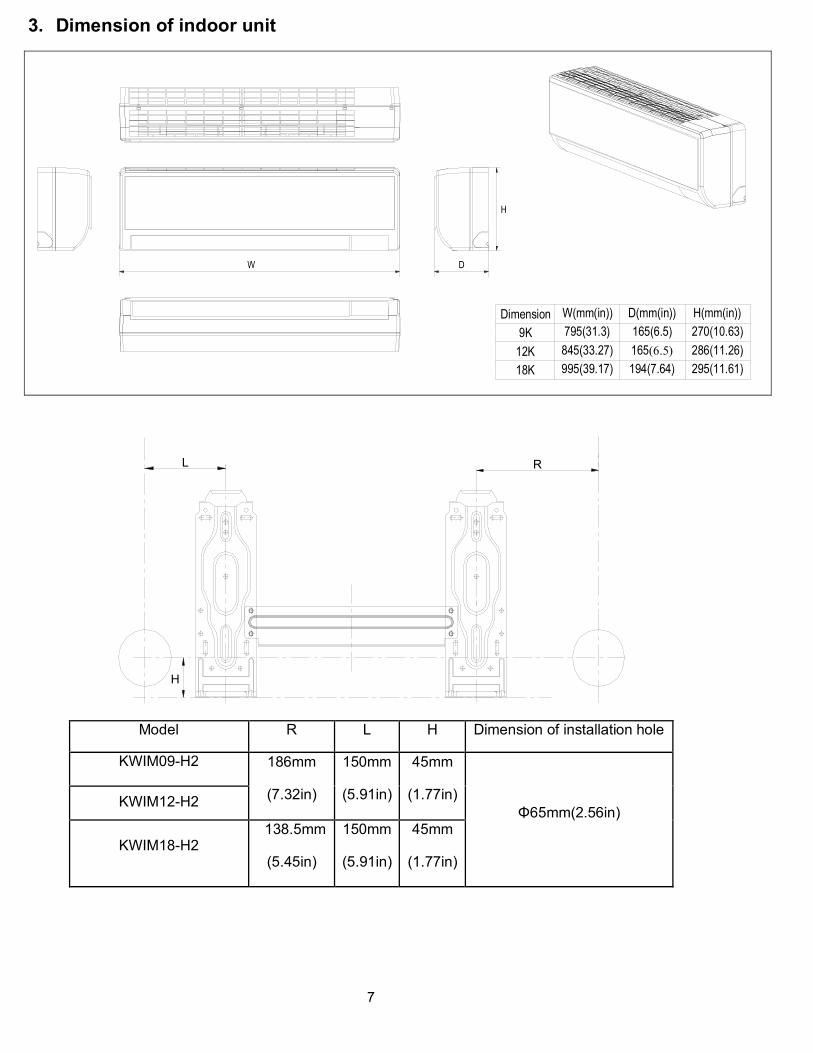
3. Dimension of indoor unit
W(mm(in)) D(mm(in)) H(mm(in))
9K 795(31.3) 165(6.5) 270(10.63)
12K 845(33.27) 165(6.5) 286(11.26)
18K 995(39.17) 194(7.64) 295(11.61)
Dimension
W D
H
L R
H
Model R L H Dimension of installation hole
KWIM09-H2 186mm
(7.32in)
150mm
(5.91in)
45mm
(1.77in) Φ65mm(2.56in)
KWIM12-H2
KWIM18-H2138.5mm
(5.45in)
150mm
(5.91in)
45mm
(1.77in)
8
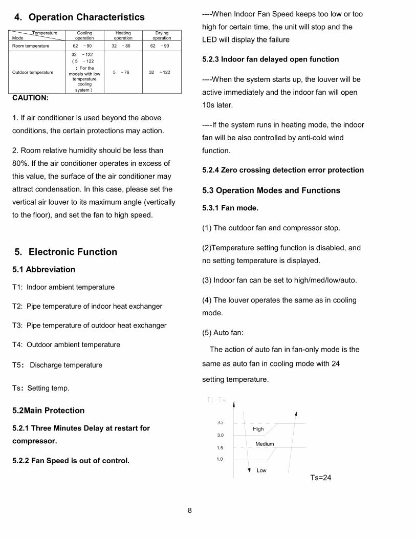
4. Operation Characteristics
Temperature Mode
Cooling operation
Heating operation
Drying operation
Room temperature 62~90 32~86 62~90
Outdoor temperature
32~122
(5~122
:For the
models with low temperature
cooling
system)
5~76 32~122
CAUTION:
1. If air conditioner is used beyond the above
conditions, the certain protections may action.
2. Room relative humidity should be less than
80%. If the air conditioner operates in excess of
this value, the surface of the air conditioner may
attract condensation. In this case, please set the
vertical air louver to its maximum angle (vertically
to the floor), and set the fan to high speed.
5. Electronic Function
5.1 Abbreviation
T1: Indoor ambient temperature
T2: Pipe temperature of indoor heat exchanger
T3: Pipe temperature of outdoor heat exchanger
T4: Outdoor ambient temperature
T5: Discharge temperature
Ts:Setting temp.
5.2Main Protection
5.2.1 Three Minutes Delay at restart for
compressor.
5.2.2 Fan Speed is out of control.
----When Indoor Fan Speed keeps too low or too
high for certain time, the unit will stop and the
LED will display the failure
5.2.3 Indoor fan delayed open function
----When the system starts up, the louver will be
active immediately and the indoor fan will open
10s later.
----If the system runs in heating mode, the indoor
fan will be also controlled by anti-cold wind
function.
5.2.4 Zero crossing detection error protection
5.3 Operation Modes and Functions
5.3.1 Fan mode.
(1) The outdoor fan and compressor stop.
(2)Temperature setting function is disabled, and
no setting temperature is displayed.
(3) Indoor fan can be set to high/med/low/auto.
(4) The louver operates the same as in cooling
mode.
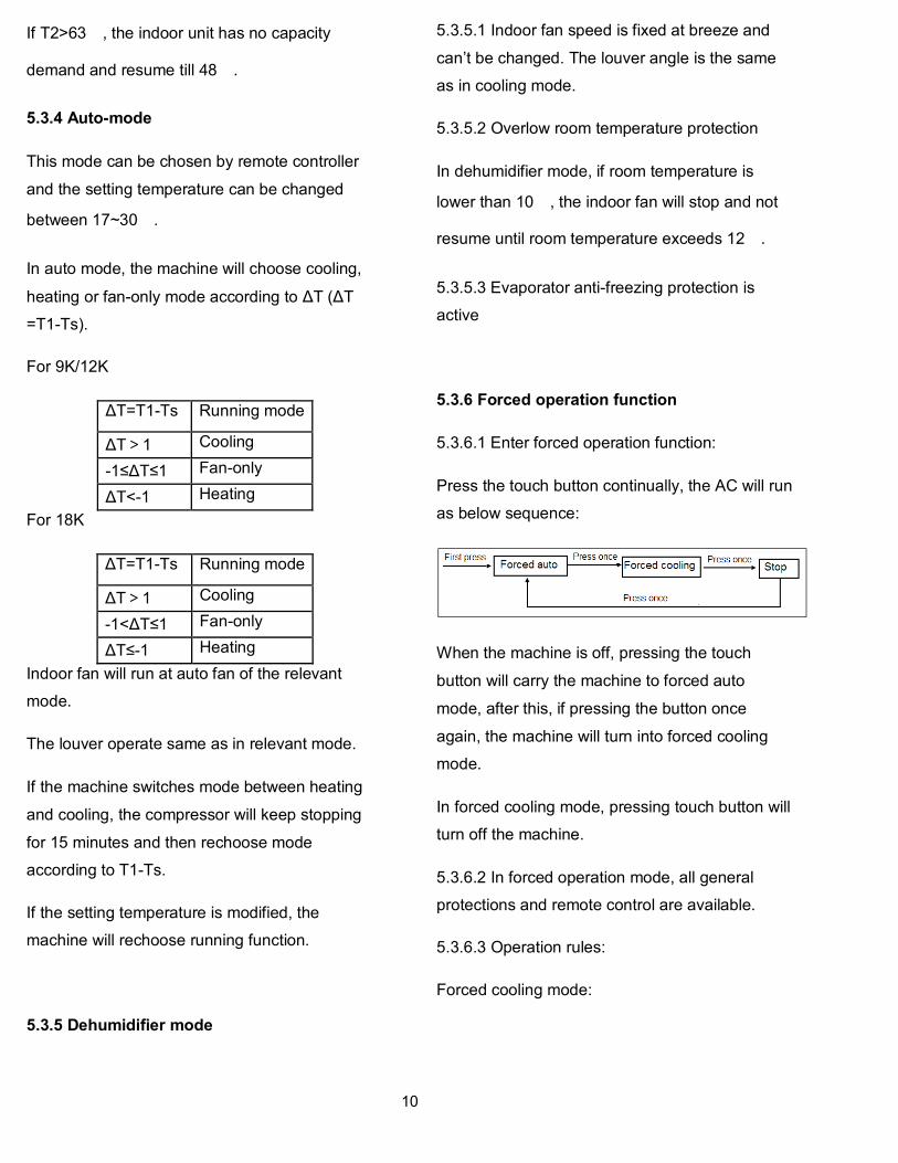
(5) Auto fan:
The action of auto fan in fan-only mode is the
same as auto fan in cooling mode with 24
setting temperature.
3.5
3.0
High
Low
1.0
Medium1.5
Ts=24

9
5.3.2 Cooling Mode
5.3.2.1 Indoor fan running rules
In cooling mode, indoor fan runs all the time and
the speed can be selected as high, medium, low
and auto.
Auto fan in cooling mode acts as follow:
3.5
3.0
High
Low
1.0
Medium1.5
5.3.2.4 Evaporator low temperature T2
protection.
When T2<4, the indoor has no capacity
demand and resume till T2>8.
5.3.3 Heating Mode
5.3.3.1 Indoor fan running rules:
Indoor fan speed can be set as high, medium, low
and auto fan and the anti-cold-wind function is
preferential.
For 9K/12K
44
3837
34
T2
33
Setting
Low
Breeze
OffTEL0
Super
Breeze
TEL1
For 18K
39
3635
T2
32
Setting
Low
Breeze
OffTEL0
Super
Breeze
TEL1
44
Medium
Auto fan action in heating mode.
2.5
2
High
Low
1
Medium
1.5
5.3.3.2 High evaporator coil temp.T2
protection:
10
If T2>63, the indoor unit has no capacity
demand and resume till 48.
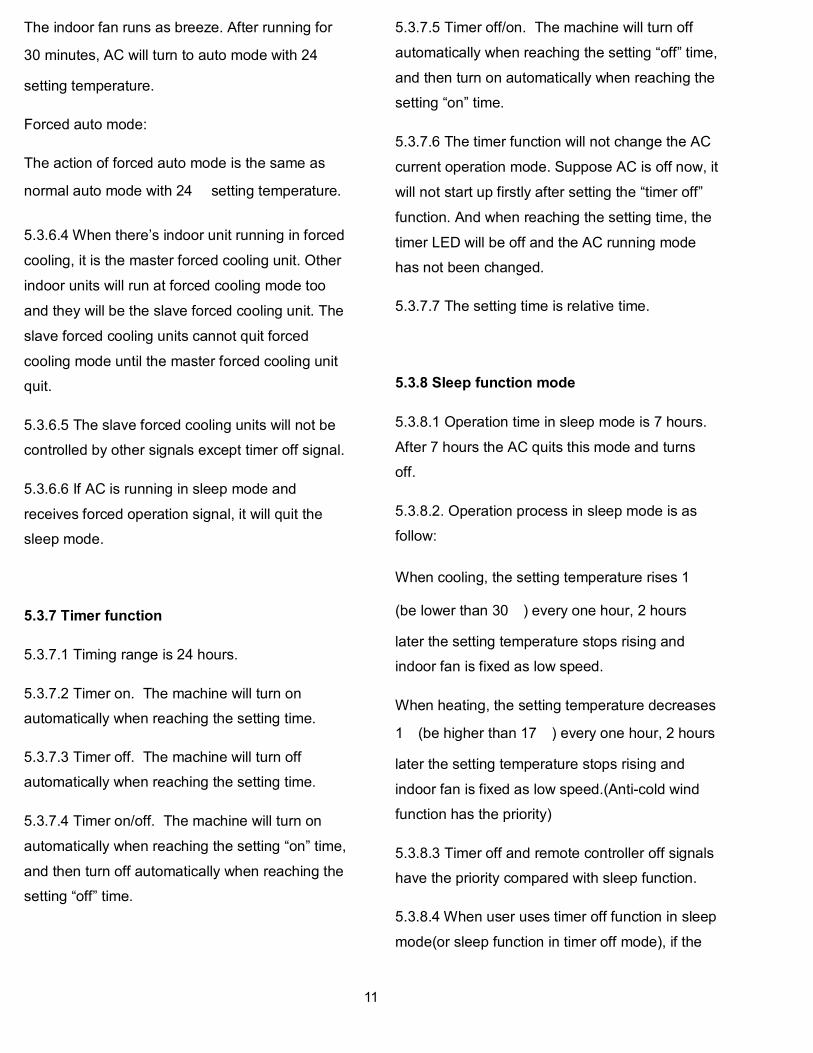
5.3.4 Auto-mode
This mode can be chosen by remote controller
and the setting temperature can be changed
between 17~30.
In auto mode, the machine will choose cooling,
heating or fan-only mode according to ΔT (ΔT
=T1-Ts).
For 9K/12K
ΔT=T1-Ts Running mode
ΔT>1 Cooling
-1≤ΔT≤1 Fan-only
ΔT<-1 Heating
For 18K
ΔT=T1-Ts Running mode
ΔT>1 Cooling
-1<ΔT≤1 Fan-only
ΔT≤-1 Heating
Indoor fan will run at auto fan of the relevant
mode.
The louver operate same as in relevant mode.
If the machine switches mode between heating
and cooling, the compressor will keep stopping
for 15 minutes and then rechoose mode
according to T1-Ts.
If the setting temperature is modified, the
machine will rechoose running function.
5.3.5 Dehumidifier mode
5.3.5.1 Indoor fan speed is fixed at breeze and
can’t be changed. The louver angle is the same
as in cooling mode.
5.3.5.2 Overlow room temperature protection
In dehumidifier mode, if room temperature is
lower than 10, the indoor fan will stop and not
resume until room temperature exceeds 12.
5.3.5.3 Evaporator anti-freezing protection is
active
5.3.6 Forced operation function
5.3.6.1 Enter forced operation function:
Press the touch button continually, the AC will run
as below sequence:
When the machine is off, pressing the touch
button will carry the machine to forced auto
mode, after this, if pressing the button once
again, the machine will turn into forced cooling
mode.
In forced cooling mode, pressing touch button will
turn off the machine.
5.3.6.2 In forced operation mode, all general
protections and remote control are available.
5.3.6.3 Operation rules:
Forced cooling mode:
11
The indoor fan runs as breeze. After running for
30 minutes, AC will turn to auto mode with 24
setting temperature.
Forced auto mode:
The action of forced auto mode is the same as
normal auto mode with 24 setting temperature.
5.3.6.4 When there’s indoor unit running in forced
cooling, it is the master forced cooling unit. Other
indoor units will run at forced cooling mode too
and they will be the slave forced cooling unit. The
slave forced cooling units cannot quit forced
cooling mode until the master forced cooling unit
quit.
5.3.6.5 The slave forced cooling units will not be
controlled by other signals except timer off signal.
5.3.6.6 If AC is running in sleep mode and
receives forced operation signal, it will quit the
sleep mode.
5.3.7 Timer function
5.3.7.1 Timing range is 24 hours.
5.3.7.2 Timer on. The machine will turn on
automatically when reaching the setting time.
5.3.7.3 Timer off. The machine will turn off
automatically when reaching the setting time.
5.3.7.4 Timer on/off. The machine will turn on
automatically when reaching the setting “on” time,
and then turn off automatically when reaching the
setting “off” time.
5.3.7.5 Timer off/on. The machine will turn off
automatically when reaching the setting “off” time,
and then turn on automatically when reaching the
setting “on” time.
5.3.7.6 The timer function will not change the AC
current operation mode. Suppose AC is off now, it
will not start up firstly after setting the “timer off”
function. And when reaching the setting time, the
timer LED will be off and the AC running mode
has not been changed.
5.3.7.7 The setting time is relative time.
5.3.8 Sleep function mode
5.3.8.1 Operation time in sleep mode is 7 hours.
After 7 hours the AC quits this mode and turns
off.
5.3.8.2. Operation process in sleep mode is as
follow:
When cooling, the setting temperature rises 1
(be lower than 30) every one hour, 2 hours
later the setting temperature stops rising and
indoor fan is fixed as low speed.
When heating, the setting temperature decreases
1(be higher than 17) every one hour, 2 hours
later the setting temperature stops rising and
indoor fan is fixed as low speed.(Anti-cold wind
function has the priority)
5.3.8.3 Timer off and remote controller off signals
have the priority compared with sleep function.
5.3.8.4 When user uses timer off function in sleep
mode(or sleep function in timer off mode), if the

12
timing is less than 7 hours, sleep function will be
cancelled when reaching the setting time. If the
timing is more than 7 hours, the machine will not
stop until reaches the setting time in sleep mode.
5.3.9 Auto-Restart function
The indoor unit is equipped with auto-restart
function, which is carried out through an auto-
restart module. In case of a sudden power failure,
the module memorizes the setting conditions
before the power failure. The unit will resume the
previous operation setting (not including Swing
function) automatically after 3 minutes when
power returns.
If the memorization condition is forced cooling
mode, the unit will run in cooling mode for 30
minutes and turn to auto mode as 24 setting
temp.
5.3.10 Ionizer
The indoor unit is equipped with Ionizer, which is
controlled by the CLEAN AIR button on the
remote controller. When the unit is turned on,
press the CLEAN AIR button to activate the
function. Press it again to stop the function.
During the time when Ionizer is controlled by
remote controller, Ionizer will be turned off
automatically if indoor fan stops running due to
malfunctions or anti-cold-wind. When indoor fan
restarts after malfunctions being eliminated and
anti-cold-wind being released, Ionizer will be
available again.

13
6. Wiring Diagrams
KWIM09-H2, KWIM12-H2, KWIM18-H2

14
7. Troubleshooting
7.1 Display Function
TIMER display
Illuminated during Timer operation.
CLEAN AIR display(optional)
Illuminated when Ionizer is activated.
TURBO operation display
Illuminated when select TURBO function in cooling operation or in
heating operation.
DIGITAL DISPLAY
Displayed the current setting temperature or malfunction code when
the air conditioner is in operation. When SELF CLEAN feature is
activated, it displays . “SC”
FAN SPEED display
Displayed the selected fan speed: LOW( ), MED( ) and
HIGH( ).
Operation Frequency display
This display is separated into five zones. The zones illuminate based on
the compressor current frequency. For example, higher frequency will
Illuminate more zones.

15
7.2Indoor Unit Error Display
Display Failure
E0 Indoor EEPROM malfunction
E1 Indoor/ outdoor units communication error
E2 Zero-crossing signal error
E3 Indoor fan speed has been out of control
E5 Open circuit or short circuit of outdoor temperature sensor or outdoor EEPROM
malfunction
E6 Open circuit or short circuit of T1 or T2 temperature sensor
P0 IPM module protection or IGBT over-strong current protection
P1 Voltage protection
P2 Temperature protection of compressor top
P3 Outdoor temperature is lower than -15°C (optional function)
P4 Inverter compressor drive protection
P5 Mode conflict
Note
P3: If the outdoor temperature <= -15 °C for 1 hour, then the machine stops running, the indoor display
shows the error code "P3“. The unit can still receive remote control signals.
If the outdoor >= -12 °C for 10 minutes, the compressor stops running more than one hour,
Or the outdoor temperature>= 5 for 10 minutes, then AC will recover to the last mode and fan
speed.
E4 : Reserved function.

16
7.3 Outdoor Unit Error Display
For KSIM20912-H216 - 2G, KSIM30912-H216 - 1G, KSIM330-H219, KSIM40912-H216 - 2G
Display LED STATUS
IDU
Error
(KWIL / KWIM)
IDU
Error
(KDIM
E0 Outdoor EEPROM malfunction E5 E6
E2 Indoor / outdoor units communication error E1 E2
E3 Communication malfunction between IPM board and outdoor main board —— ——
E4 Open or short circuit of outdoor temperature sensor(T3、T4、T5、T2B) E5 E6
E5 Voltage protection P1 P0
E6 PFC module protection(Only for KSIM40912-H216 - 2G) —— ——
E8 Outdoor fan speed has been out of control(Only for DC fan motor models) —— ——
F1 No A Indoor unit coil outlet temp. sensor or connector of sensor is defective —— ——
F2 No B Indoor unit coil outlet temp. sensor or connector of sensor is defective —— ——
F3 No C Indoor unit coil outlet temp. sensor or connector of sensor is defective —— ——
F4 No D Indoor unit coil outlet temp. sensor or connector of sensor is defective —— ——
P0 Temperature protection of compressor top (Only for KSIM30912-H216 - 1G) P2 P3
P1 High pressure protection (Only for KSIM40912-H216 - 2G) —— ——
P2 Low pressure protection(Only for KSIM40912-H216 - 2G) —— ——
P3 Current protection of compressor —— ——
P4 Temperature protection of compressor discharge —— ——
P5 High temperature protection of condenser —— ——
P6 IPM module protection P0 E5

17
For M2OC-18HRDN1-M, M3OC-27HRDN1-M, KSIM40912-H216 - 1G
Display digital tube
LED STATUS IDU
Error (KWIL / KWIM)
IDU Error
KDIM
E0 Outdoor EEPROM malfunction E5 E6
E1 No A Indoor unit coil outlet temp. sensor or connector of sensor is defective —— ——
E2 No B Indoor unit coil outlet temp. sensor or connector of sensor is defective —— ——
E3 No C Indoor unit coil outlet temp. sensor or connector of sensor is defective —— ——
E6 No D Indoor unit coil outlet temp. sensor or connector of sensor is defective —— ——
E4 Open or short circuit of outdoor temperature sensor(T4) E5 E6
E5 Voltage protection P1 P0
E7 Communication malfunction between IPM board and outdoor main board —— ——
P0 Temperature protection of compressor discharge (Temperature protection of compressor top(only for KSIM20912-H216 - 1G & KSIM30912-H216 - 2G) )
P2 P3
P1 High pressure protection (Only for KSIM40912-H216 - 1G) —— ——
P2 Low pressure protection(Only for KSIM40912-H216 - 1G) —— ——
P3 Current protection of compressor —— ——
P4 IPM module protection P0 E5
P6 High temperature protection of condenser —— ——
P7 Inverter compressor drive protection P4 P4
PF PFC module protection(Only for KSIM40912-H216 - 1G) —— ——

18
7.4 Diagnosis and Solution
7.4.1 Indoor unit trouble shooting
7.4.1.1 E0(Indoor EEPROM malfunction) error diagnosis and solution
Error Code E0
Malfunction decision conditions
PCB main chip does not receive feedback from EEPROM chip
Supposed causes Installation mistake
PCB faulty
Trouble shooting:
EEPROM: a read-only memory whose contents can be erased and reprogrammed using a pulsed voltage.
For the location of EEPROM chip, please refer to the below photos.
19
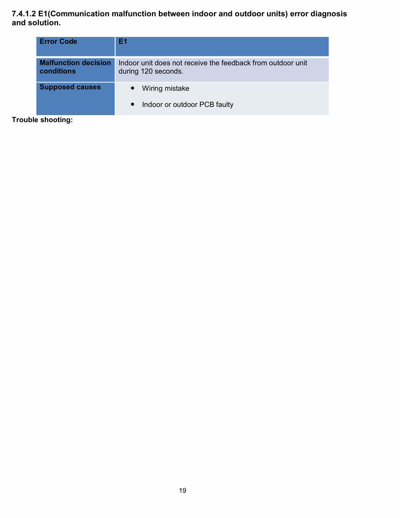
7.4.1.2 E1(Communication malfunction between indoor and outdoor units) error diagnosis and solution.
Error Code E1
Malfunction decision conditions
Indoor unit does not receive the feedback from outdoor unit during 120 seconds.
Supposed causes Wiring mistake
Indoor or outdoor PCB faulty
Trouble shooting:

20
21
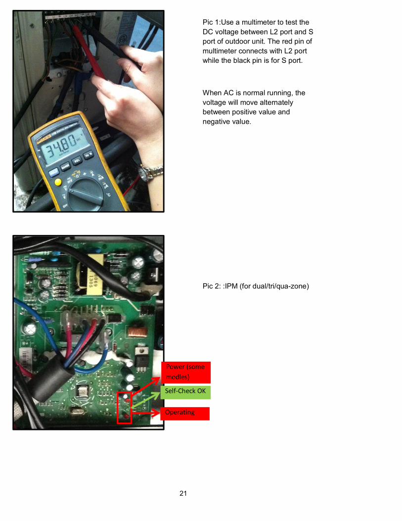
Pic 1:Use a multimeter to test the
DC voltage between L2 port and S
port of outdoor unit. The red pin of
multimeter connects with L2 port
while the black pin is for S port.
When AC is normal running, the
voltage will move alternately
between positive value and
negative value.
Pic 2: :IPM (for dual/tri/qua-zone)
Self-Check OK
Power (some
modles)
Operating

22
PIC 4: Check point button, press 1 time for check
how many indoor units are connected.(for
KSIM20912-H216 - 2G,KSIM30912-H216 - 1G,KSIM330-H219,KSIM40912-H216 - 2G)
Check point button, press 18 times for check how
many indoor units are connected.(for KSIM20912-H216 - 1G, KSIM30912-H216 - 1G, KSIM40912-H216 - 1G)
PIC3 :Main board LED when power on and unit
standby.

23
7.4.1.3 E2(zero-crossing signal error) diagnosis and solution.
Error Code E2
Malfunction decision conditions
When PCB does not receive zero crossing signal feedback for 4 minutes or the zero crossing signal time interval is abnormal.
Supposed causes Connection mistake
PCB faulty
Trouble shooting:
24
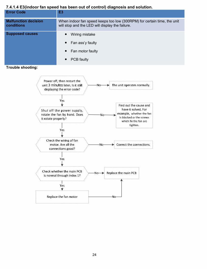
7.4.1.4 E3(indoor fan speed has been out of control) diagnosis and solution.
Error Code E3
Malfunction decision conditions
When indoor fan speed keeps too low (300RPM) for certain time, the unit will stop and the LED will display the failure.
Supposed causes Wiring mistake
Fan ass’y faulty
Fan motor faulty
PCB faulty
Trouble shooting:

25
Index 1:
1: Indoor AC fan motor
Power on and set the unit running in fan mode at high fan speed. After running for 15 seconds, measure
the voltage of pin1 and pin2. If the value of the voltage is less than 100V(208~240V power supply)or
50V(115V power supply), the PCB must have problems and need to be replaced.
26
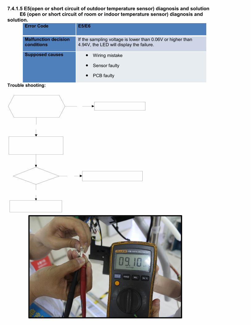
7.4.1.5 E5(open or short circuit of outdoor temperature sensor) diagnosis and solution E6 (open or short circuit of room or indoor temperature sensor) diagnosis and
solution.
Error Code E5/E6
Malfunction decision conditions
If the sampling voltage is lower than 0.06V or higher than 4.94V, the LED will display the failure.
Supposed causes Wiring mistake
Sensor faulty
PCB faulty
Trouble shooting:

27
7.4.1.6 P0(IPM module or IGBT over-strong current protection) diagnosis and solution.
Error Code P6
Malfunction decision conditions
When the voltage signal that IPM send to compressor drive chip is abnormal, the display LED will show “P6” and AC will turn off.
Supposed causes Wiring mistake
IPM malfunction
Outdoor fan ass’y faulty
Compressor malfunction
Outdoor PCB faultyTrouble shooting:

28
29
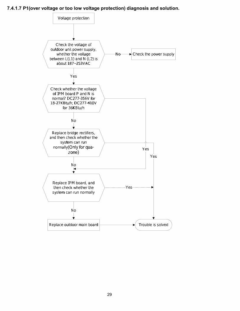
7.4.1.7 P1(over voltage or too low voltage protection) diagnosis and solution.

30
7.4.1.8 P2( temperature protection of compressor top) diagnosis and solution.
Error Code P2
Malfunction decision conditions
If the sampling voltage is not 5V, the LED will display the failure.
Supposed causes Wiring mistake
Over load protector faulty
System block
Outdoor PCB faulty
7.4.1.9 P4 Inverter compressor drive error diagnosis and solution
The trouble shooting is same with one of IPM module protection(P0).
31
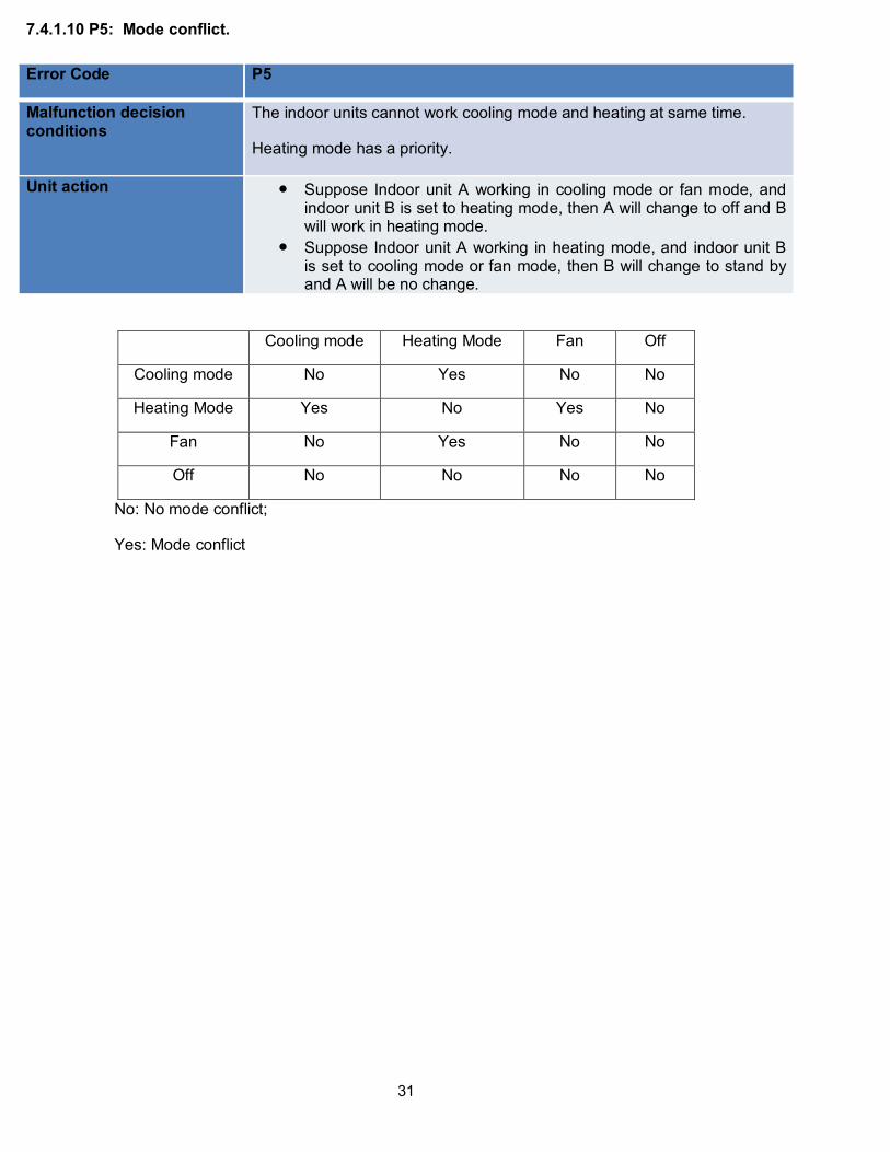
7.4.1.10 P5: Mode conflict.
Error Code P5
Malfunction decision conditions
The indoor units cannot work cooling mode and heating at same time.
Heating mode has a priority.
Unit action Suppose Indoor unit A working in cooling mode or fan mode, andindoor unit B is set to heating mode, then A will change to off and Bwill work in heating mode.
Suppose Indoor unit A working in heating mode, and indoor unit Bis set to cooling mode or fan mode, then B will change to stand byand A will be no change.
Cooling mode Heating Mode Fan Off
Cooling mode No Yes No No
Heating Mode Yes No Yes No
Fan No Yes No No
Off No No No No
No: No mode conflict;
Yes: Mode conflict

32
7.4.2 Outdoor unit trouble shooting (For KSIM20912-H216 - 2G, KSIM218-H221,KSIM30912-H216 - 1G, KSIM330-H219, KSIM40912-H216 - 2G)7.4.2.1 E0(Outdoor EEPROM malfunction) error diagnosis and solution
Error Code E0
Malfunction decision conditions
PCB main chip does not receive feedback from EEPROM chip
Supposed causes Installation mistake
PCB faulty
Trouble shooting:
EEPROM: a read-only memory whose contents can be erased and reprogrammed using a pulsed voltage.
For the location of EEPROM chip, please refer to the below photos.
Outdoor PCB(KSIM330-H219)

33
7.4.2.2 E2(Communication malfunction between indoor and outdoor units) error diagnosis and solution.
Error Code E2
Malfunction decision conditions
Indoor unit does not receive the feedback from outdoor unit during 120 seconds or outdoor unit does not receive the feedback from any one indoor unit during 180 seconds.
Supposed causes Wiring mistake
Indoor or outdoor PCB faulty
Trouble shooting:

34

35
Pic 1:Use a multimeter to test the
DC voltage between L2 port and S
port of outdoor unit. The red pin of
multimeter connects with L2 port
while the black pin is for S port.
When AC is normal running, the
voltage will move alternately
between positive value and
negative value.
Pic 2: :IPM (For dual/tri-zone)
Self-Check
Operating

36
PIC 4: Check point button, press 1 time for check
how many indoor units are connected.
Self-Check
Power,
Operating
PIC3 :Main board LED when power on and unit
standby.
Pic 2: :IPM (For qua-zone)

37
7.4.2.3 E3(Communication malfunction between IPM board and outdoor main board) error diagnosis and
.
Error Code E3
Malfunction decision conditions
PCB main chip does not receive feedback from IPM module during 60 seconds.
Supposed causes Wiring mistake
PCB faulty
Trouble shooting:

38
Remark:
Use a multimeter to test the DC
voltage between black pin and
white pin of signal wire The normal
value should be around 5V.
Use a multimeter to test the DC
voltage between black pin and red
pin of signal wire. The normal value
should be around 12V.
39
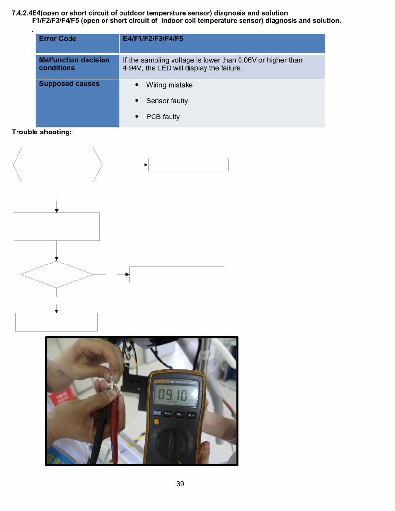
7.4.2.4E4(open or short circuit of outdoor temperature sensor) diagnosis and solution F1/F2/F3/F4/F5 (open or short circuit of indoor coil temperature sensor) diagnosis and solution.
.
Error Code E4/F1/F2/F3/F4/F5
Malfunction decision conditions
If the sampling voltage is lower than 0.06V or higher than 4.94V, the LED will display the failure.
Supposed causes Wiring mistake
Sensor faulty
PCB faulty
Trouble shooting:

40
7.4.2.5 E5(Voltage protection) error diagnosis and solution.
Error Code E5
Malfunction decision conditions
An abnormal voltage rise or drop is detected by checking the specified voltage detection circuit.
Supposed causes Power supply problems.
System leakage or block
PCB faulty
Trouble shooting:
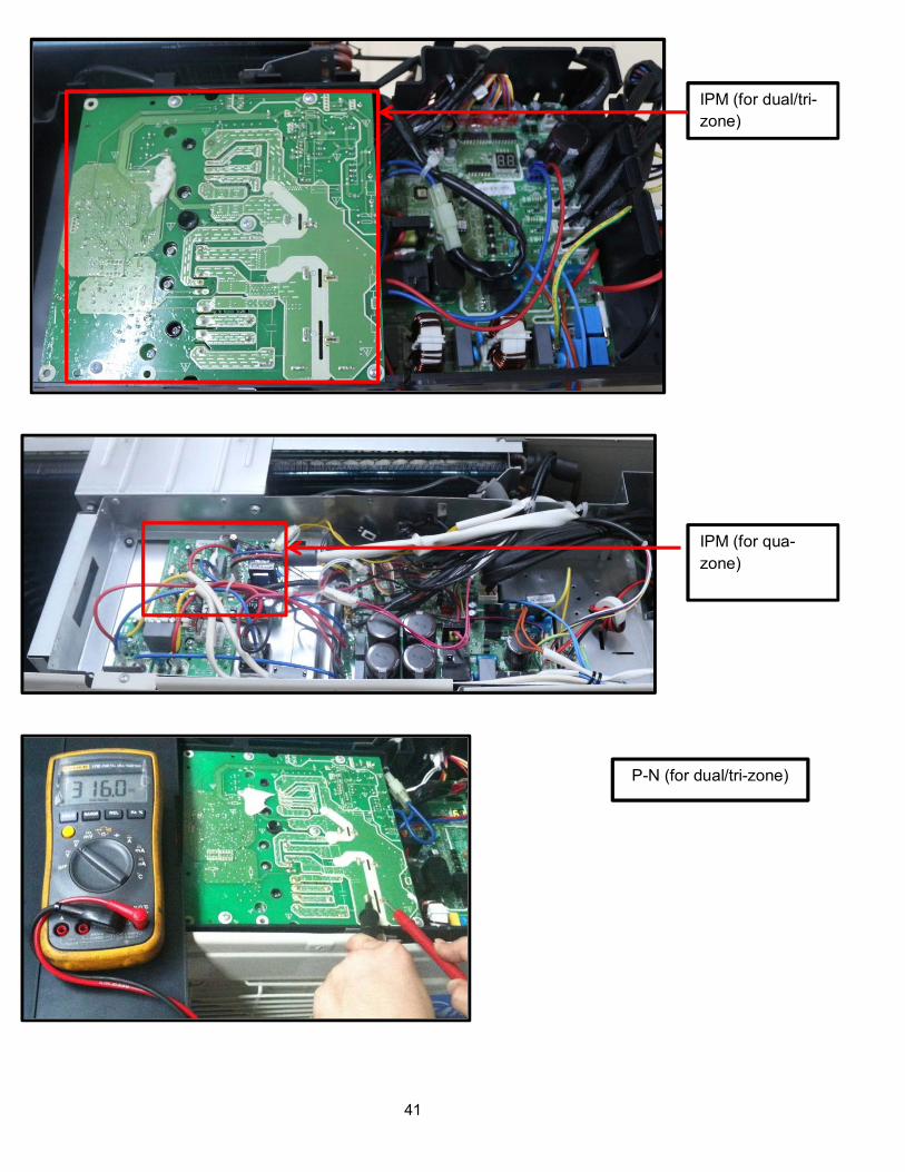
41
IPM (for dual/tri-
zone)
IPM (for qua-
zone)
P-N (for dual/tri-zone)

42
P-N (for qua-zone)

43
bridge rectifier
(for dual/tri-zone)
bridge rectifier
(for qua-zone)
44
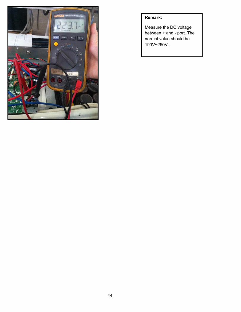
Remark:
Measure the DC voltage
between + and - port. The
normal value should be
190V~250V.

45
7.4.2.6 E6(PFC module protection) error diagnosis and solution. (Only for KSIM40912-H216 - 2G)
Error Code E6
Malfunction decision conditions
When the voltage signal that PFC sends to main control board is abnormal, the display LED will show “E6” and AC will turn off.
Supposed causes Wiring mistake
Outdoor PCB faulty
Inductance of PFC module faulty
PFC module malfunctionTrouble shooting:

46
Two ports of the inductance
Inductance

47

48
7.4.2.7 E8(Outdoor fan speed has been out of control) diagnosis and solution(Only for DC fan motor models).
Error Code E8
Malfunction decision conditions
When outdoor fan speed keeps too low (300RPM) or too high(2400RPM) for certain time, the unit will stop and the LED will display the failure.
Supposed causes Wiring mistake
Fan ass’y faulty
Fan motor faulty
PCB faultyTrouble shooting:

49
Index 1:
1. DC fan motor(control chip is inside fan motor)
Power on and when the unit is in standby, measure the voltage of pin1-pin3, pin4-pin3 in fan motor
connector. If the value of the voltage is not in the range showing in below table, the PCB must have
problems and need to be replaced.
DC motor voltage input and output
NO. Color Signal Voltage
1 Red Vs/Vm 200~380V
2 --- --- ---
3 Black GND 0V
4 White Vcc 13.5~16.5V
5 Yellow Vsp 0~6.5V
6 Blue FG 13.5~16.5V
Vs Vcc

50
Vsp FG

51
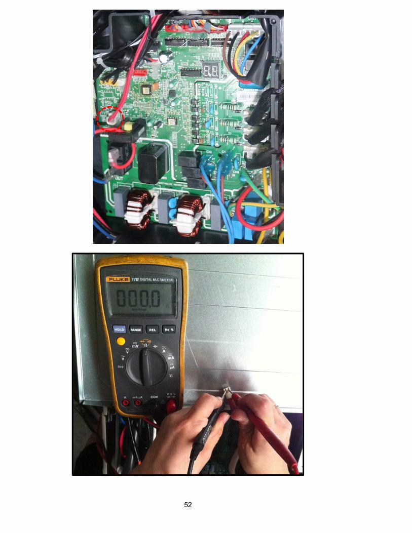
7.4.2.8 P0(Temperature protection of compressor top) error diagnosis and solution. (Only for
KSIM30912-H216 - 1G)
Error Code P0
Malfunction decision
conditions
If the sampling voltage is not 5V, the LED will display the failure.
Supposed causes Wiring mistake
Over load protector faulty
System block
Outdoor PCB faulty
Trouble shooting:
52

53
7.4.2.9 P1(High pressure protection) error diagnosis and solution. (Only for KSIM40912-H216 - 2G)
Error Code P1
Malfunction decision conditions
If the sampling voltage is not 5V, the LED will display the failure.
Supposed causes Wiring mistake
Over load protector faulty
System block
Outdoor PCB faultyTrouble shooting:

54

55
56
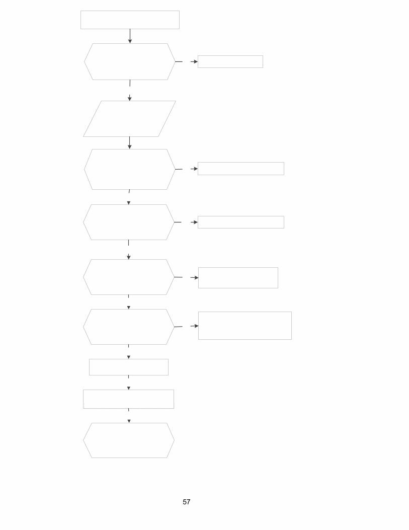
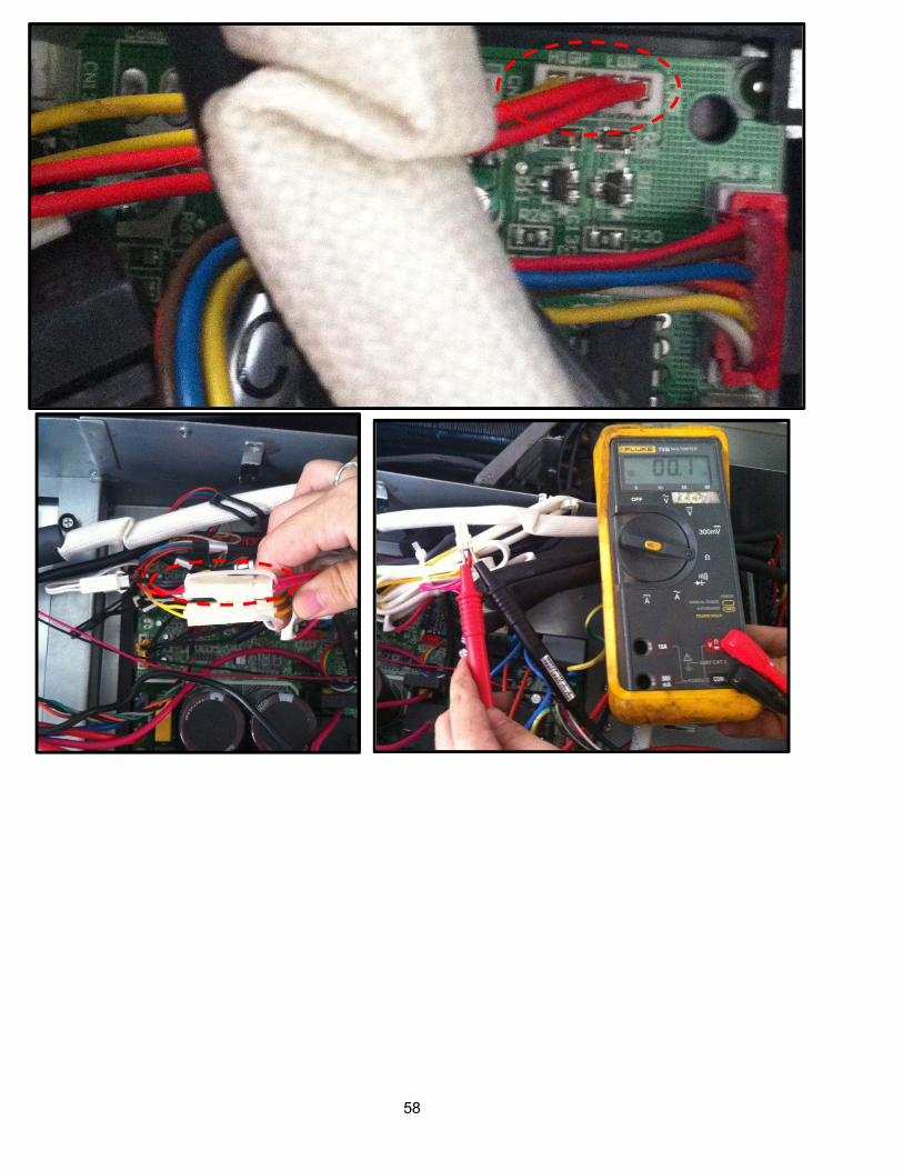
7.4.2.10 P2(Low pressure protection) error diagnosis and solution. (Only for KSIM40912-H216 - 2G)
Error Code P2
Malfunction decision conditions
If the sampling voltage is not 5V, the LED will display the failure.
Supposed causes Wiring mistake
Over load protector faulty
System block
Outdoor PCB faultyTrouble shooting:
57
#
58

59
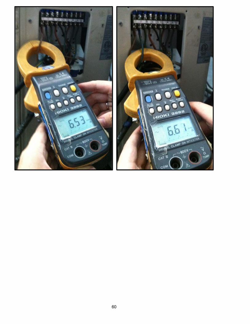
7.4.2.11 P3(Current protection of compressor) error diagnosis and solution.
Error Code P3
Malfunction decision conditions
If the outdoor current exceeds the current limit value, the LED will display the failure.
Supposed causes Wiring mistake
Over load protector faulty
System block
Outdoor PCB faultyTrouble shooting:
60
61
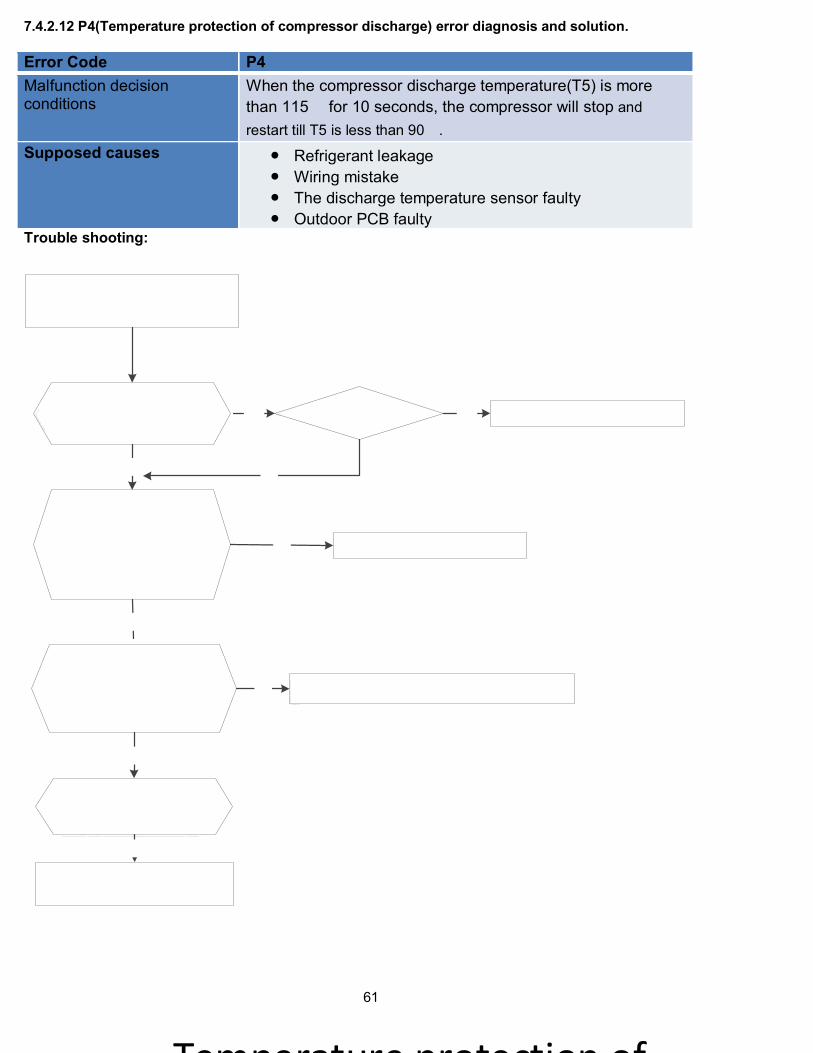
7.4.2.12 P4(Temperature protection of compressor discharge) error diagnosis and solution.
Error Code P4
Malfunction decision conditions
When the compressor discharge temperature(T5) is more
than 115 for 10 seconds, the compressor will stop and
restart till T5 is less than 90.
Supposed causes Refrigerant leakage
Wiring mistake
The discharge temperature sensor faulty
Outdoor PCB faultyTrouble shooting:
2

62
7.4.2.13 P5(High temperature protection of condenser) error diagnosis and solution.
Error Code P5
Malfunction decision conditions
When outdoor pipe temperature is more than 65°C, the unit will stop, and unit runs again when outdoor pipe temperature is less than 52°C
Supposed causes The condenser temperature sensor faulty
Heat exchanger dirty
System blockTrouble shooting:

63
7.4.2.14 P6(IPM module protection) error diagnosis and solution.
Error Code P6
Malfunction decision conditions
When the voltage signal that IPM send to compressor drive chip is abnormal, the display LED will show “P6” and AC will turn off.
Supposed causes Wiring mistake
IPM malfunction
Outdoor fan ass’y faulty
Compressor malfunction
Outdoor PCB faultyTrouble shooting:

64

65
7.4.3 Outdoor unit trouble shooting (For KSIM20912-H216 - 1G, KSIM30912-H216 - 1G, KSIM40912-
H216 - 1G 7.4.3.1 E0(Outdoor EEPROM malfunction) error diagnosis and solution
Error Code E0
Malfunction decision conditions
PCB main chip does not receive feedback from EEPROM chip
Supposed causes Installation mistake
PCB faulty
Trouble shooting:
EEPROM: a read-only memory whose contents can be erased and reprogrammed using a pulsed voltage.
For the location of EEPROM chip, please refer to the below photos.
Outdoor PCB(KSIM20912-H216 - 1G)
66
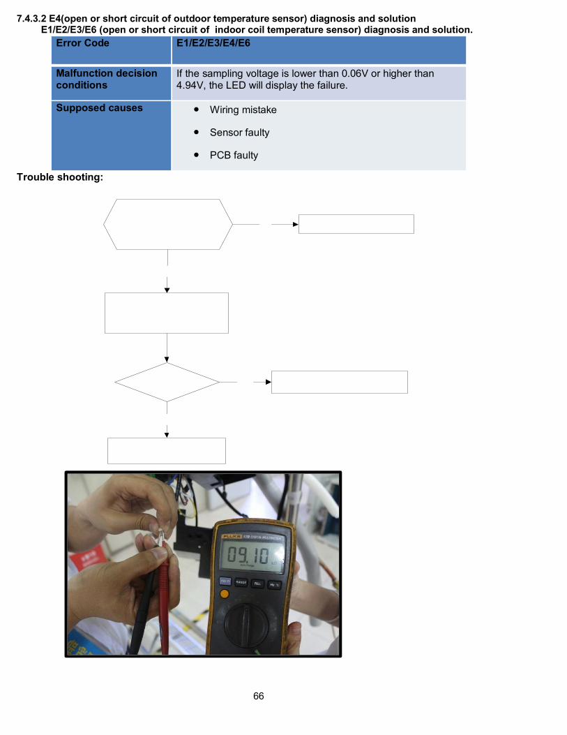
7.4.3.2 E4(open or short circuit of outdoor temperature sensor) diagnosis and solution E1/E2/E3/E6 (open or short circuit of indoor coil temperature sensor) diagnosis and solution.
Error Code E1/E2/E3/E4/E6
Malfunction decision conditions
If the sampling voltage is lower than 0.06V or higher than 4.94V, the LED will display the failure.
Supposed causes Wiring mistake
Sensor faulty
PCB faulty
Trouble shooting:
67
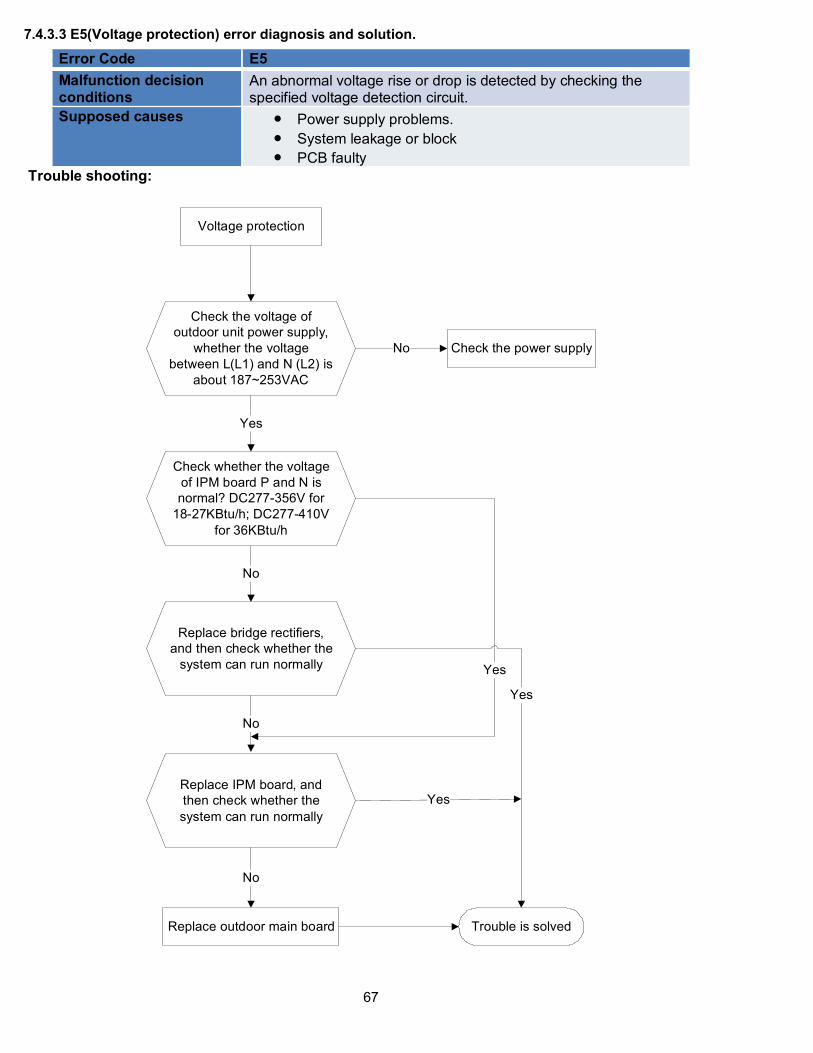
7.4.3.3 E5(Voltage protection) error diagnosis and solution.
Error Code E5
Malfunction decision conditions
An abnormal voltage rise or drop is detected by checking the specified voltage detection circuit.
Supposed causes Power supply problems.
System leakage or block
PCB faulty
Trouble shooting:
Voltage protection
Check the voltage of
outdoor unit power supply,
whether the voltage
between L(L1) and N (L2) is
about 187~253VAC
Check the power supply
Check whether the voltage
of IPM board P and N is
normal? DC277-356V for
18-27KBtu/h; DC277-410V
for 36KBtu/h
Replace bridge rectifiers,
and then check whether the
system can run normally
Replace IPM board, and
then check whether the
system can run normally
Replace outdoor main board
Yes
No
No
No
No
Yes
Trouble is solved
Yes
Yes
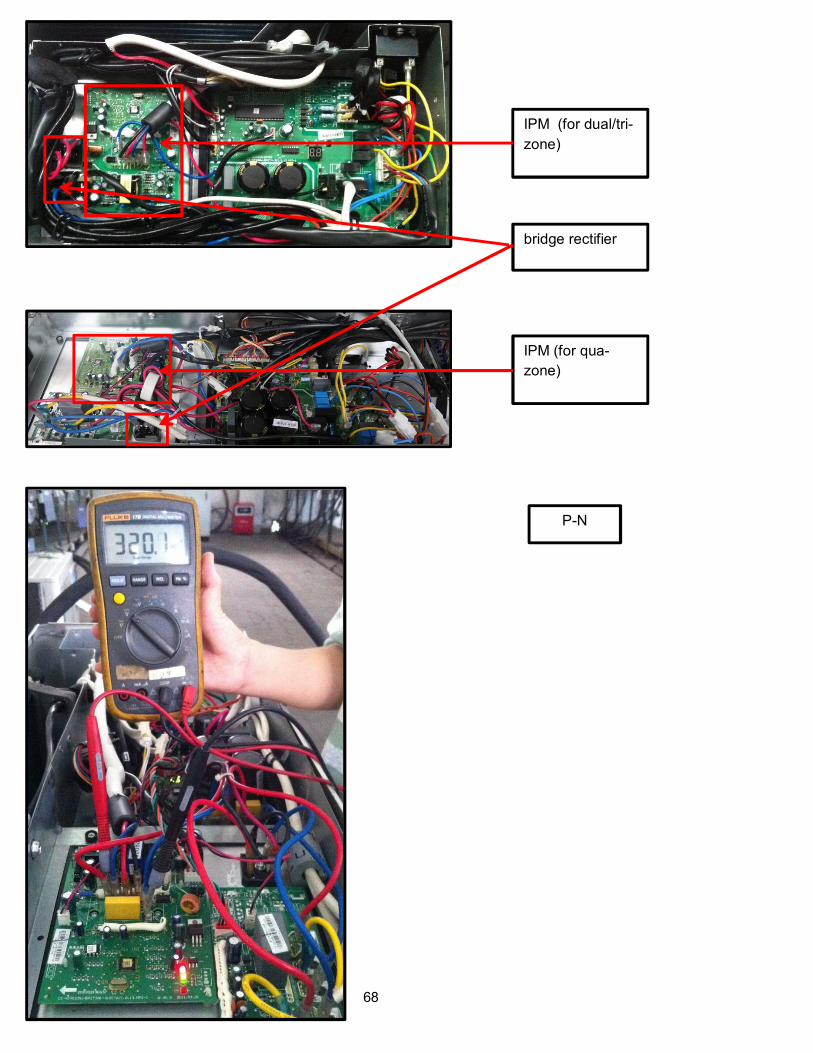
68
IPM (for dual/tri-
zone)
IPM (for qua-
zone)
bridge rectifier
P-N

69
Remark:
Measure the DC voltage
between + and - port. The
normal value should be
190V~250V.

70
7.4.3.4 E7(Communication malfunction between IPM board and outdoor main board) error diagnosis and
.
Error Code E7
Malfunction decision conditions
PCB main chip does not receive feedback from IPM module during 60 seconds.
Supposed causes Wiring mistake
PCB faulty
Trouble shooting:
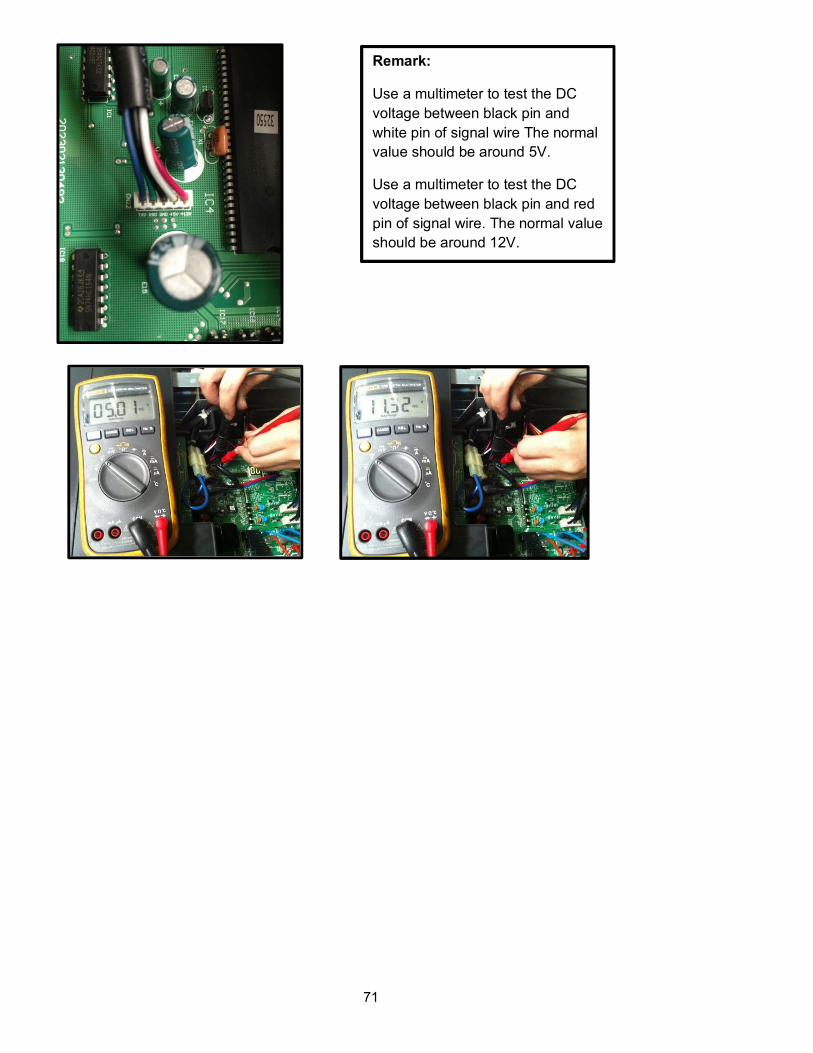
71
Remark:
Use a multimeter to test the DC
voltage between black pin and
white pin of signal wire The normal
value should be around 5V.
Use a multimeter to test the DC
voltage between black pin and red
pin of signal wire. The normal value
should be around 12V.
72
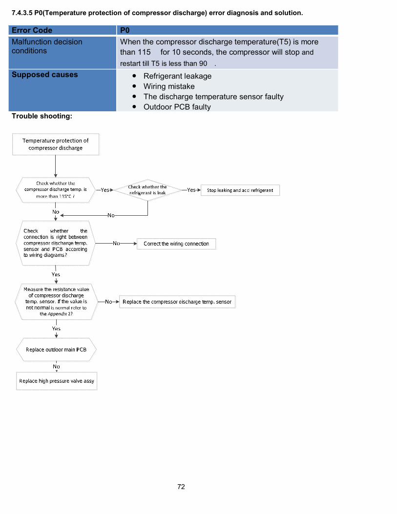
7.4.3.5 P0(Temperature protection of compressor discharge) error diagnosis and solution.
Error Code P0
Malfunction decision conditions
When the compressor discharge temperature(T5) is more
than 115 for 10 seconds, the compressor will stop and
restart till T5 is less than 90.
Supposed causes Refrigerant leakage
Wiring mistake
The discharge temperature sensor faulty
Outdoor PCB faultyTrouble shooting:
73
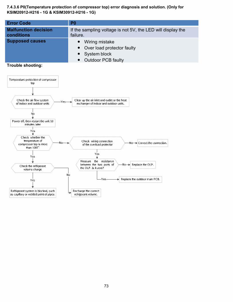
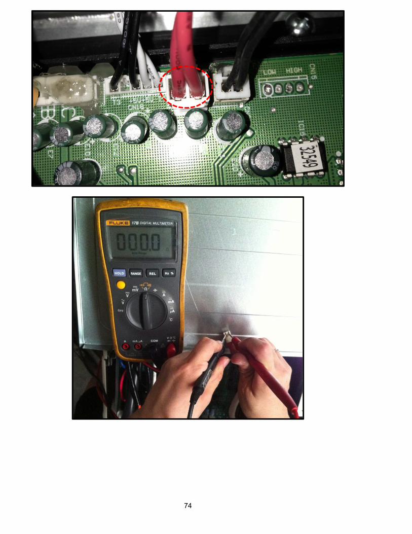
7.4.3.6 P0(Temperature protection of compressor top) error diagnosis and solution. (Only for
KSIM20912-H216 - 1G & KSIM30912-H216 - 1G)
Error Code P0
Malfunction decision conditions
If the sampling voltage is not 5V, the LED will display the failure.
Supposed causes Wiring mistake
Over load protector faulty
System block
Outdoor PCB faultyTrouble shooting:
74

75
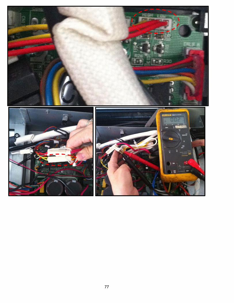
7.4.3.7 P1(High pressure protection) error diagnosis and solution. (Only for KSIM40912-H216 - 1G)
Error Code P1
Malfunction decision conditions
If the sampling voltage is not 5V, the LED will display the failure.
Supposed causes Wiring mistake
Over load protector faulty
System block
Outdoor PCB faultyTrouble shooting:

76
77

78
7.4.3.8 P2(Low pressure protection) error diagnosis and solution. (Only for KSIM40912-H216 - 1G)
Error Code P2
Malfunction decision conditions
If the sampling voltage is not 5V, the LED will display the failure.
Supposed causes Wiring mistake
Over load protector faulty
System block
Outdoor PCB faultyTrouble shooting:

79
#

80

81
7.4.3.9 P3(Current protection of compressor) error diagnosis and solution.
Error Code P3
Malfunction decision conditions
If the outdoor current exceeds the current limit value, the LED will display the failure.
Supposed causes Wiring mistake
Over load protector faulty
System block
Outdoor PCB faultyTrouble shooting:

82

83
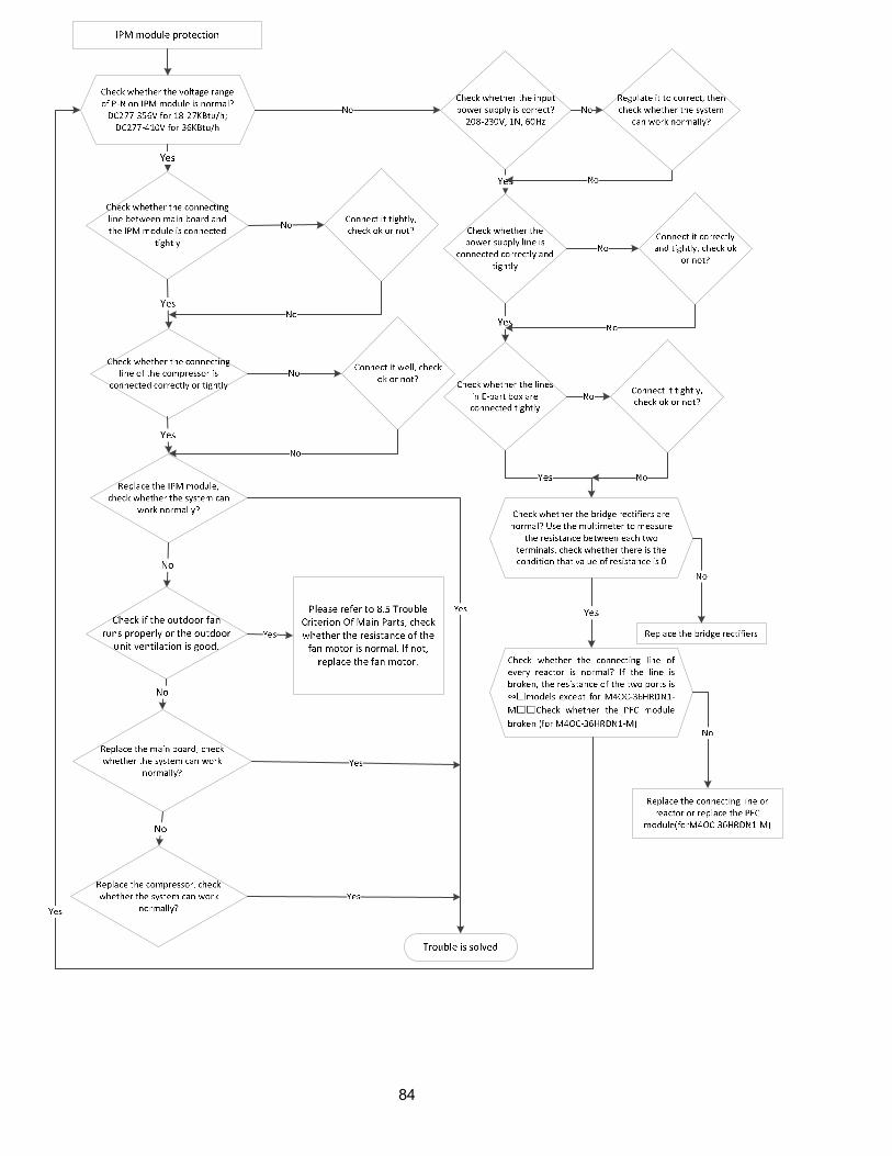
7.4.3.10 P4(IPM module protection) error diagnosis and solution.
Error Code P4
Malfunction decision conditions
When the voltage signal that IPM send to compressor drive chip is abnormal, the display LED will show “P4” and AC will turn off.
Supposed causes Wiring mistake
IPM malfunction
Outdoor fan ass’y faulty
Compressor malfunction
Outdoor PCB faultyTrouble shooting:
84
85
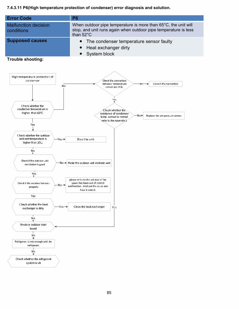
7.4.3.11 P6(High temperature protection of condenser) error diagnosis and solution.
Error Code P6
Malfunction decision conditions
When outdoor pipe temperature is more than 65°C, the unit will stop, and unit runs again when outdoor pipe temperature is less than 52°C
Supposed causes The condenser temperature sensor faulty
Heat exchanger dirty
System blockTrouble shooting:
86
7.4.3.12 P7(Inverter compressor drive protection) error diagnosis and solution.
The same as P4(IPM module protection)
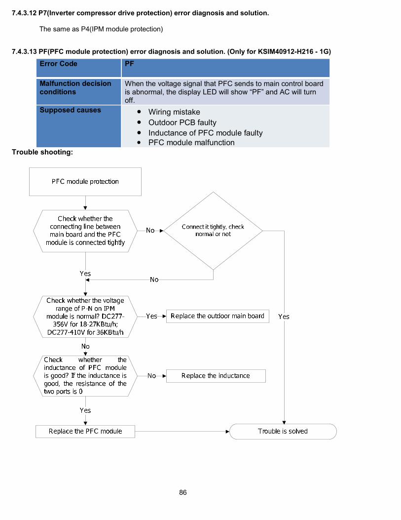
7.4.3.13 PF(PFC module protection) error diagnosis and solution. (Only for KSIM40912-H216 - 1G)
Error Code PF
Malfunction decision conditions
When the voltage signal that PFC sends to main control board is abnormal, the display LED will show “PF” and AC will turn off.
Supposed causes Wiring mistake
Outdoor PCB faulty
Inductance of PFC module faulty
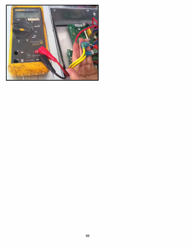
PFC module malfunctionTrouble shooting:

87
Two ports of the inductance
Inductance
88
89
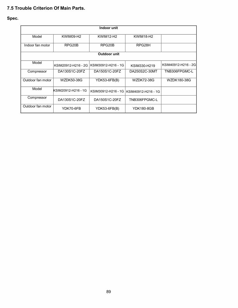
7.5 Trouble Criterion Of Main Parts.
Spec.
Indoor unit
Model KWIM09-H2 KWIM12-H2 KWIM18-H2
Indoor fan motor RPG20B RPG20B RPG28H
Outdoor unit
Model KSIM30912-H216 - 1G KSIM40912-H216 - 2G
Compressor DA130S1C-20FZ DA150S1C-20FZ DA250S2C-30MT TNB306FPGMC-L
Outdoor fan motor WZDK50-38G YDK53-6FB(B) WZDK72-38G WZDK180-38G
Model KSIM20912-H216 - 1G KSIM30912-H216 - 1G
Compressor DA130S1C-20FZ DA150S1C-20FZ TNB306FPGMC-L
Outdoor fan motor YDK70-6FB YDK53-6FB(B) YDK180-8GB
KSIM20912-H216 - 2G KSIM330-H219
KSIM40912-H216 - 1G
90
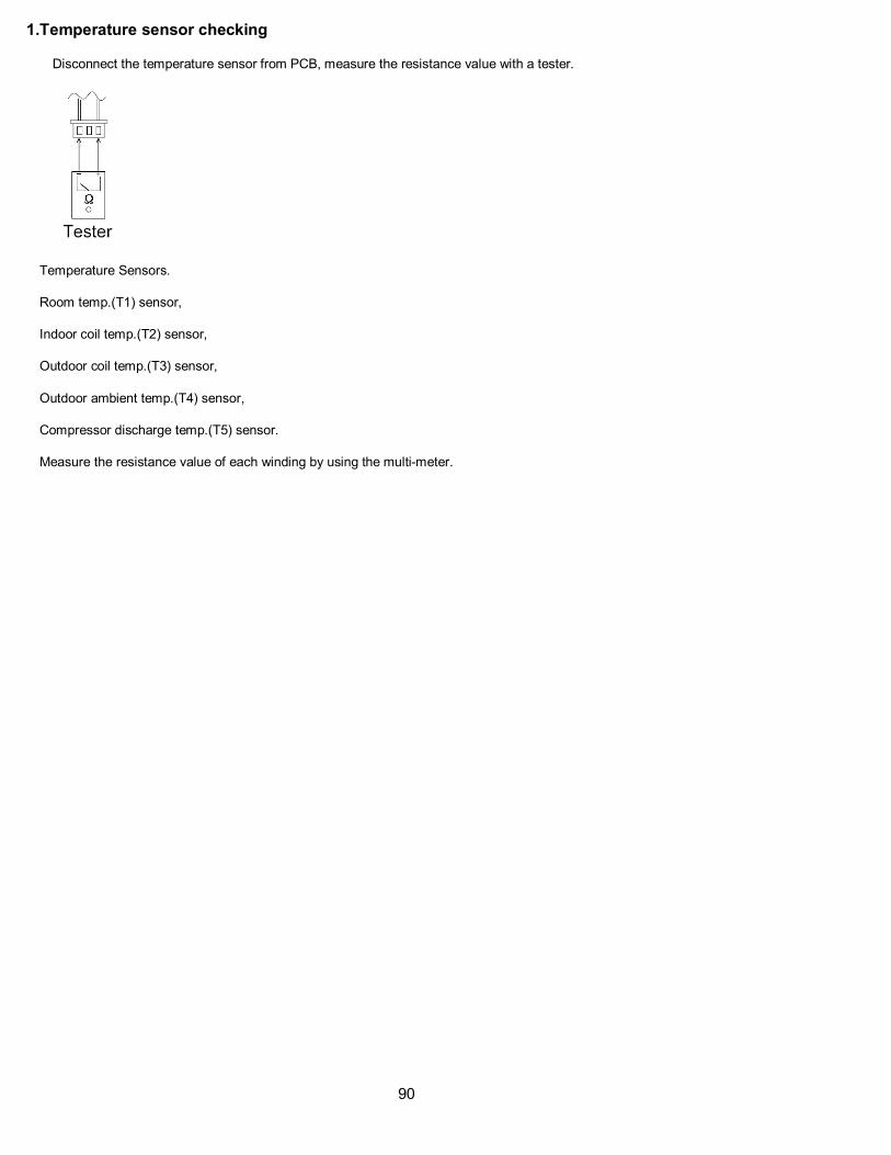
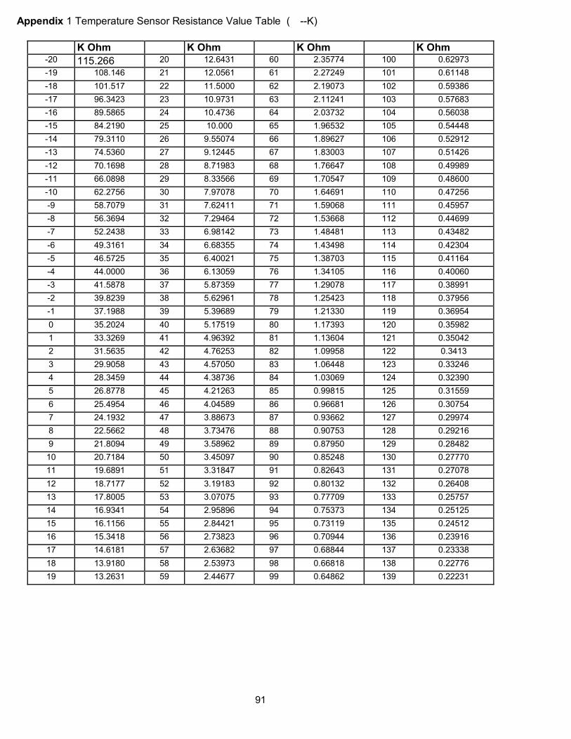
1.Temperature sensor checking
Disconnect the temperature sensor from PCB, measure the resistance value with a tester.
Temperature Sensors.
Room temp.(T1) sensor,
Indoor coil temp.(T2) sensor,
Outdoor coil temp.(T3) sensor,
Outdoor ambient temp.(T4) sensor,
Compressor discharge temp.(T5) sensor.
Measure the resistance value of each winding by using the multi-meter.
91
Appendix 1 Temperature Sensor Resistance Value Table (--K)
K Ohm K Ohm K Ohm K Ohm -20 115.266 20 12.6431 60 2.35774 100 0.62973
-19 108.146 21 12.0561 61 2.27249 101 0.61148
-18 101.517 22 11.5000 62 2.19073 102 0.59386
-17 96.3423 23 10.9731 63 2.11241 103 0.57683
-16 89.5865 24 10.4736 64 2.03732 104 0.56038
-15 84.2190 25 10.000 65 1.96532 105 0.54448
-14 79.3110 26 9.55074 66 1.89627 106 0.52912
-13 74.5360 27 9.12445 67 1.83003 107 0.51426
-12 70.1698 28 8.71983 68 1.76647 108 0.49989
-11 66.0898 29 8.33566 69 1.70547 109 0.48600
-10 62.2756 30 7.97078 70 1.64691 110 0.47256
-9 58.7079 31 7.62411 71 1.59068 111 0.45957
-8 56.3694 32 7.29464 72 1.53668 112 0.44699
-7 52.2438 33 6.98142 73 1.48481 113 0.43482
-6 49.3161 34 6.68355 74 1.43498 114 0.42304
-5 46.5725 35 6.40021 75 1.38703 115 0.41164
-4 44.0000 36 6.13059 76 1.34105 116 0.40060
-3 41.5878 37 5.87359 77 1.29078 117 0.38991
-2 39.8239 38 5.62961 78 1.25423 118 0.37956
-1 37.1988 39 5.39689 79 1.21330 119 0.36954
0 35.2024 40 5.17519 80 1.17393 120 0.35982
1 33.3269 41 4.96392 81 1.13604 121 0.35042
2 31.5635 42 4.76253 82 1.09958 122 0.3413
3 29.9058 43 4.57050 83 1.06448 123 0.33246
4 28.3459 44 4.38736 84 1.03069 124 0.32390
5 26.8778 45 4.21263 85 0.99815 125 0.31559
6 25.4954 46 4.04589 86 0.96681 126 0.30754
7 24.1932 47 3.88673 87 0.93662 127 0.29974
8 22.5662 48 3.73476 88 0.90753 128 0.29216
9 21.8094 49 3.58962 89 0.87950 129 0.28482
10 20.7184 50 3.45097 90 0.85248 130 0.27770
11 19.6891 51 3.31847 91 0.82643 131 0.27078
12 18.7177 52 3.19183 92 0.80132 132 0.26408
13 17.8005 53 3.07075 93 0.77709 133 0.25757
14 16.9341 54 2.95896 94 0.75373 134 0.25125
15 16.1156 55 2.84421 95 0.73119 135 0.24512
16 15.3418 56 2.73823 96 0.70944 136 0.23916
17 14.6181 57 2.63682 97 0.68844 137 0.23338
18 13.9180 58 2.53973 98 0.66818 138 0.22776
19 13.2631 59 2.44677 99 0.64862 139 0.22231

92
Appendix 2
Unit: ---K Discharge temp. sensor table
-20 542.7 20 68.66 60 13.59 100 3.702
-19 511.9 21 65.62 61 13.11 101 3.595
-18 483 22 62.73 62 12.65 102 3.492
-17 455.9 23 59.98 63 12.21 103 3.392
-16 430.5 24 57.37 64 11.79 104 3.296
-15 406.7 25 54.89 65 11.38 105 3.203
-14 384.3 26 52.53 66 10.99 106 3.113
-13 363.3 27 50.28 67 10.61 107 3.025
-12 343.6 28 48.14 68 10.25 108 2.941
-11 325.1 29 46.11 69 9.902 109 2.86
-10 307.7 30 44.17 70 9.569 110 2.781
-9 291.3 31 42.33 71 9.248 111 2.704
-8 275.9 32 40.57 72 8.94 112 2.63
-7 261.4 33 38.89 73 8.643 113 2.559
-6 247.8 34 37.3 74 8.358 114 2.489
-5 234.9 35 35.78 75 8.084 115 2.422
-4 222.8 36 34.32 76 7.82 116 2.357
-3 211.4 37 32.94 77 7.566 117 2.294
-2 200.7 38 31.62 78 7.321 118 2.233
-1 190.5 39 30.36 79 7.086 119 2.174
0 180.9 40 29.15 80 6.859 120 2.117
1 171.9 41 28 81 6.641 121 2.061
2 163.3 42 26.9 82 6.43 122 2.007
3 155.2 43 25.86 83 6.228 123 1.955
4 147.6 44 24.85 84 6.033 124 1.905
5 140.4 45 23.89 85 5.844 125 1.856
6 133.5 46 22.89 86 5.663 126 1.808
7 127.1 47 22.1 87 5.488 127 1.762
8 121 48 21.26 88 5.32 128 1.717
9 115.2 49 20.46 89 5.157 129 1.674
10 109.8 50 19.69 90 5 130 1.632
11 104.6 51 18.96 91 4.849
12 99.69 52 18.26 92 4.703
13 95.05 53 17.58 93 4.562
14 90.66 54 16.94 94 4.426
15 86.49 55 16.32 95 4.294 B(25/50)=3950K
16 82.54 56 15.73 96 4.167
17 78.79 57 15.16 97 4.045 R(90)=5KΩ±3%
18 75.24 58 14.62 98 3.927
19 71.86 59 14.09 99 3.812

93
Appendix 3:
10 11 12 13 14 15 16 17 18 19 20 21 22
48 50 52 54 56 58 60 62 64 66 68 70 72
23 24 25 26 27 28 29 30 31 32 33 34 35
74 76 78 80 82 84 86 88 90 92 94 96 98
2. Compressor check
Measure the resistance value of each winding by using the tester.
Position Resistance Value
DA130S1C-20FZ DA150S1C-20FZ DA250S2C-30MT TNB306FPGMC-L
Blue - Red 0.95Ω(20) 0.95Ω(20) 0.55Ω(20) 0.53Ω(20)

94
3.IPM continuity check
Turn off the power, let the large capacity electrolytic capacitors discharge completely, and dismount the
IPM. Use a digital tester to measure the resistance between P and UVWN; UVW and N.
Digital tester Normal resistance
value Digital tester
Normal
resistance
value
(+)Red (-)Black
∞ (Several MΩ)
(+)Red (-)Black
∞ (Several MΩ)P
N U
N U V
V W
W (+)Red
4. AC Fan Motor.
Measure the resistance value of each winding by using the tester.
Position Resistance Value
RPG20B RPG28H
Black - Red 381Ω±8% (20)
(Brand: Weiling)
342Ω±8% (20)
(Brand: Dayang)
183.6Ω±8% (20)
(Brand: Weiling)
180Ω±8% (20)
(Brand: Wolong)
White - Black 267Ω±8% (20)
(Brand: Weiling)
253Ω±8% (20)
(Brand: Dayang)
206Ω±8% (20)
(Brand: Weiling)
190Ω±8% (20)
(Brand: Wolong)
Measure the resistance value of each winding by using the tester.

95
Position Resistance Value
YDK70-6FB YDK180-
8GB YSK27-4G YSK68-4B YDK45-6B YSK25-6L
YDK53-
6FB(B)
Black - Red 56Ω±8%
(20)
24.5Ω±8%
(20)
317Ω±8%
(20)
145Ω±8%
(20)
345Ω±8%
(20)
627Ω±8%
(20)
88.5Ω±8%
(20)
Red -
Yellow
76Ω±8%
(20)
19Ω±8% (20
)
252Ω±8%
(20)
88Ω±8%
(20)
150Ω±8%
(20)
374.3Ω±8%
(20)
138Ω±8% (20
)
Yellow -
Blue
76Ω±8%
(20)
19Ω±8% (20
)
252Ω±8%
(20)
88Ω±8%
(20)
150Ω±8%
(20)
374.3Ω±8%
(20)
138Ω±8% (20
)
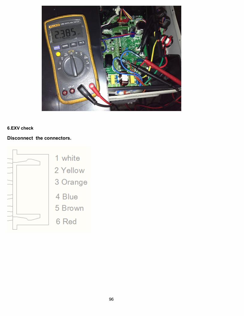
5.4-way valve
1. Power on, use a digital tester to measure the voltage, when the unit operates in cooling, it is 0V. When the
unit operates in heating, it is about 230VAC.
If the value of the voltage is not in the range, the PCB must have problems and need to be replaced.
2 Turn off the power, use a digital tester to measure the resistance. The value should be 1.8~2.5 KΩ.
96
6.EXV check
Disconnect the connectors.

97
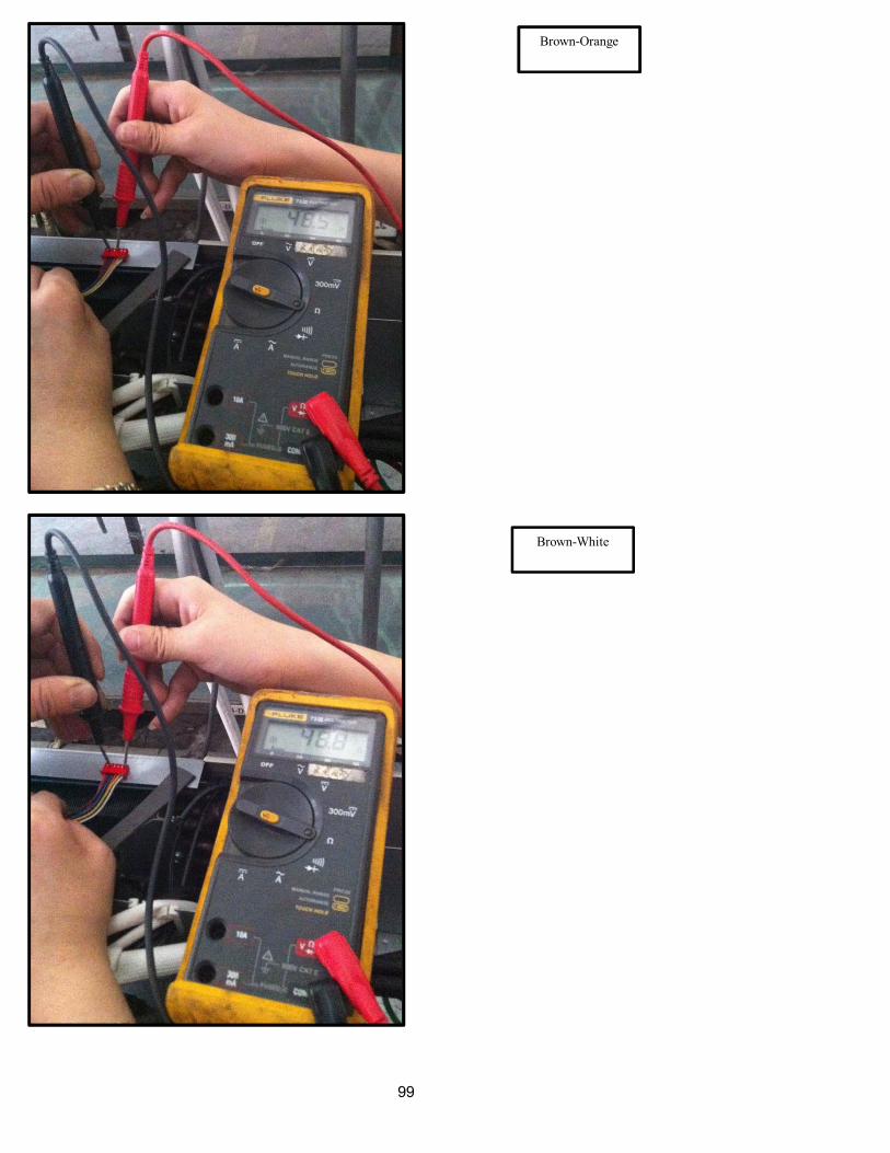
Resistance to EXV coil
Color of lead wire Normal Value
Red- Blue
About 50Ω
Red - Yellow
Brown-Orange
Brown-White

98
Red- Blue
Red - Yellow
99
Brown-Orange
Brown-White
100
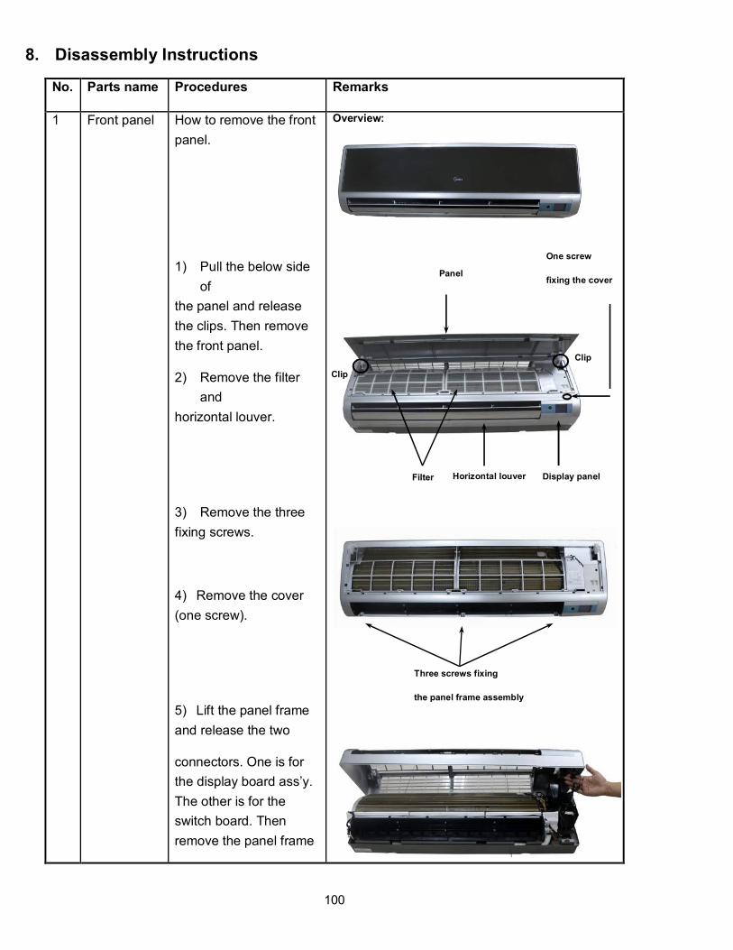
8. Disassembly Instructions
No. Parts name Procedures Remarks
1 Front panel How to remove the front
panel.
1) Pull the below side
of
the panel and release
the clips. Then remove
the front panel.
2) Remove the filter
and
horizontal louver.
3) Remove the three
fixing screws.
4) Remove the cover
(one screw).
5) Lift the panel frame
and release the two
connectors. One is for
the display board ass’y.
The other is for the
switch board. Then
remove the panel frame
Overview:
Three screws fixing
the panel frame assembly
Clip
One screw
fixing the cover
Clip
Panel
Filter Display panel Horizontal louver

101
assembly.
2 Electrical
parts
How to remove the
electrical parts.
1) After remove the
front panel from
procedure 1, pull out the
room temp. sensor and
evaporator coil sensor.
Remove the grounding
screws.
2) Remove the fixing
screw and open the
electrical box cover.
.
3) Pull out the
connectors of the swing
motor, ionizer, fan motor
and the capacitor .
Swing motors
From right to left, it is the fan motor connector,
ionizer connector, the swing motor connector
Connector of fan capacitor
Electrical box cover fixing by one screw
Grounding
screws
Evaporator coil
temp. sensor
Room temp.
sensor
102
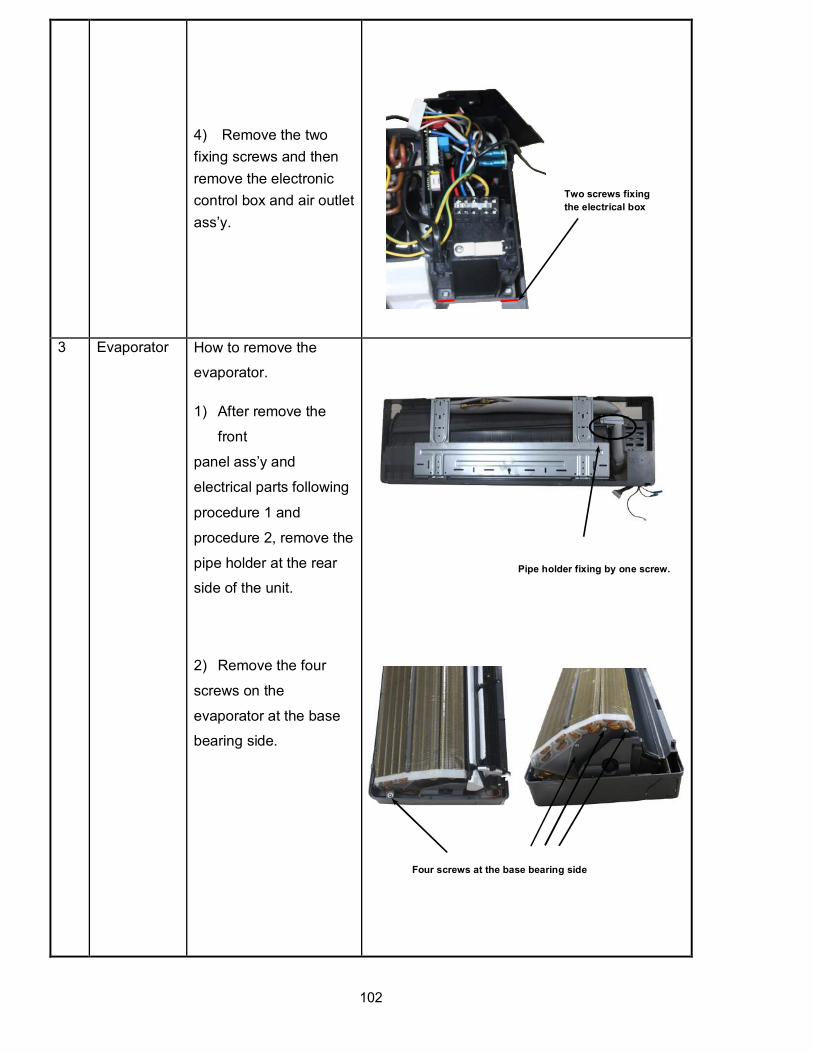
4) Remove the two
fixing screws and then
remove the electronic
control box and air outlet
ass’y.
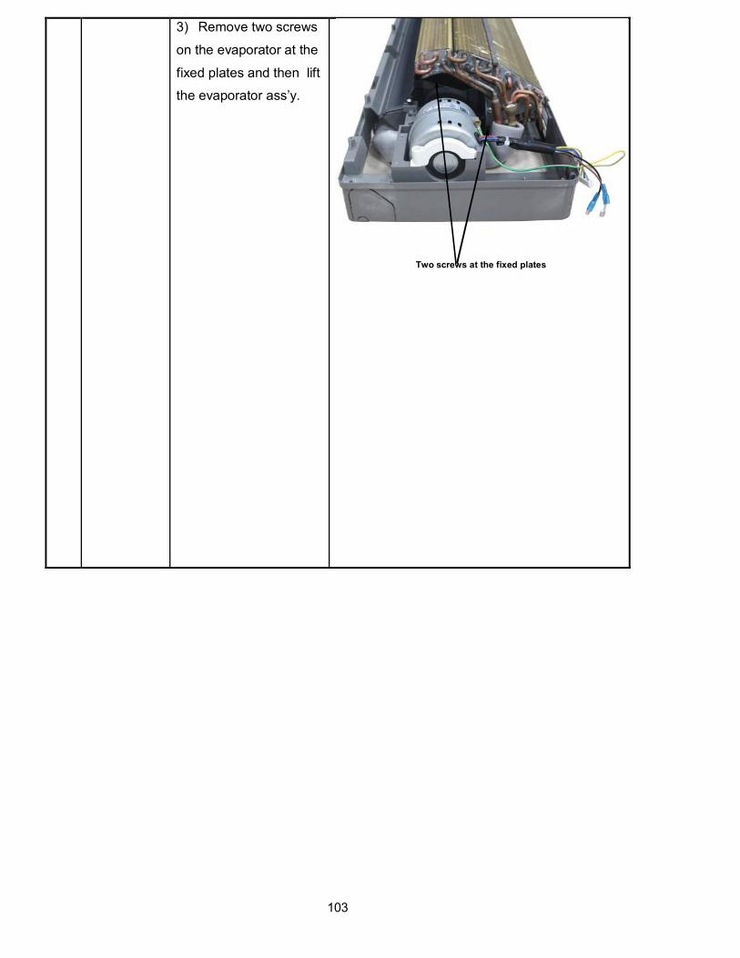
3 Evaporator How to remove the
evaporator.
1) After remove the
front
panel ass’y and
electrical parts following
procedure 1 and
procedure 2, remove the
pipe holder at the rear
side of the unit.
2) Remove the four
screws on the
evaporator at the base
bearing side.
Four screws at the base bearing side
Pipe holder fixing by one screw.
Two screws fixing
the electrical box
103
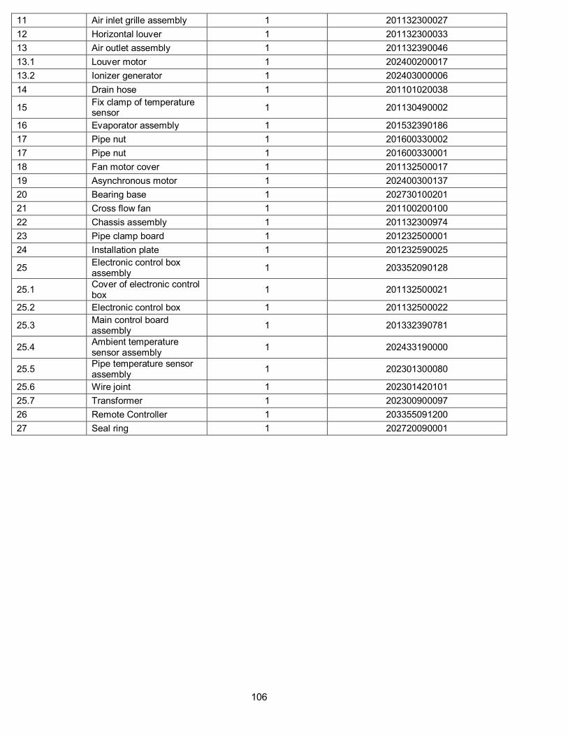
3) Remove two screws
on the evaporator at the
fixed plates and then lift
the evaporator ass’y.
Two screws at the fixed plates

104
4 Fan and
motor
How to remove the fan
and motor.
1) After remove the
evaporator ass’y
following procedure 1,
procedure 2 and
procedure 3, remove the
five screws.
2) Then separate the fan
and motor.
Five screws

105
9. Exploded View
KWIM09-H2
No. Part Name Quantity BOM code
1 Panel assembly 1 201132390011
2 Hinge Slide groove 2 201132300005
3 Air cleaner 1 201131410703
4 Bracket of air filter 1 201132200713
5 Air filter(left) 1 201132300002
6 Air filter(right) 1 201132300001
7 Display box assembly 1 203332590183
7.1 Display board assembly 1 201332590136
8 Cover of indoor electronic control box
1 201132500012
9 Screw cap 3 201132300037
10 Panel frame assembly 1 201132300895
10.1 Panel frame assembly 1 201132300026
10.1.1 Louver motor 1 202400200105
106
11 Air inlet grille assembly 1 201132300027
12 Horizontal louver 1 201132300033
13 Air outlet assembly 1 201132390046
13.1 Louver motor 1 202400200017
13.2 Ionizer generator 1 202403000006
14 Drain hose 1 201101020038
15 Fix clamp of temperature sensor
1 201130490002
16 Evaporator assembly 1 201532390186
17 Pipe nut 1 201600330002
17 Pipe nut 1 201600330001
18 Fan motor cover 1 201132500017
19 Asynchronous motor 1 202400300137
20 Bearing base 1 202730100201
21 Cross flow fan 1 201100200100
22 Chassis assembly 1 201132300974
23 Pipe clamp board 1 201232500001
24 Installation plate 1 201232590025
25 Electronic control box assembly
1 203352090128
25.1 Cover of electronic control box
1 201132500021
25.2 Electronic control box 1 201132500022
25.3 Main control board assembly
1 201332390781
25.4 Ambient temperature sensor assembly
1 202433190000
25.5 Pipe temperature sensor assembly
1 202301300080
25.6 Wire joint 1 202301420101
25.7 Transformer 1 202300900097
26 Remote Controller 1 203355091200
27 Seal ring 1 202720090001

107
KWIM12-H2
No. Part Name Quantity BOM code
1 Panel assembly 1 201132590008
2 Hinge Slide groove 2 201132500010
3 Air cleaner 1 201131410703
4 Bracket of air filter 1 201132200713
5 Air filter(left) 1 201132500013
6 Air filter(right) 1 201132500011
7 Display box assembly 1 203332590183
7.1 Display board assembly 1 201332590136
8 Cover of indoor electronic control box
1 201132500012
9 Screw cap 3 201132500055
10 Panel frame assembly 1 201132501024
10.1 Panel frame assembly 1 201132501131
10.1.1 Louver motor 1 202400200105
11 Air inlet grille assembly 1 201132500054
13 Air outlet assembly 1 201132590969
13.1 Louver motor 1 202400200017
13.2 Ionizer generator 1 202403000006
13.3 Horizontal louver 1 201132500060
14 Drain hose 1 201101020038

108
15 Fix clamp of temperature sensor
1 201130490002
16 Evaporator assembly 1 201532590004
17 Pipe nut 1 201600330003
17 Pipe nut 1 201600330001
18 Fan motor cover 1 201132500017
19 Asynchronous motor 1 202400300137
20 Bearing base 1 202730100201
21 Cross flow fan 1 201100200106
22 Chassis assembly 1 201132500007
23 Pipe clamp board 1 201232500001
24 Installation plate 1 201232590025
25 Electronic control box assembly
1 203352090129
25.1 Cover of electronic control box
1 201132500021
25.2 Electronic control box 1 201132500022
25.3 Main control board assembly
1 201332590505
25.4 Ambient temperature sensor assembly
1 202433190000
25.5 Pipe temperature sensor assembly
1 202301300080
25.6 Wire joint 1 202301420101
25.7 Transformer 1 202300900097
26 Remote Controller 1 203355091200

109
KWIM18-H2
No. Part Name Quantity BOM code
1 Panel assembly 1 201132890054
2 Hinge Slide groove 2 201132890023
3 Air cleaner 1 201131410703
4 Bracket of air filter 1 201132200713
5 Air filter(left) 1 201132890025
6 Air filter(right) 1 201132890024
7 Display box assembly 1 203332890007
7.1 Display board assembly 1 201332890026
8 Cover of indoor electronic control box
1 201132490008
9 Screw cap 3 201132890026
10 Panel frame assembly 1 201132890584
10.1 Panel frame assembly 1 201132890019
10.1.1 Louver motor 1 202400200042
12 Horizontal louver 1 201132890060
13 Air outlet assembly 1 201132890678
13.1 Louver motor 1 202400200040
13.2 Ionizer generator 1 202403000003
14 Drain hose 1 201101020038
15 Fix clamp of temperature sensor
1 201102000305
16 Evaporator assembly 1 201532890109

110
17 Pipe nut 1 201600330003
17 Pipe nut 1 201600330001
18 Fan motor cover 1 201132890021
19 Asynchronous motor 1 202400300419
20 Bearing base 1 202730100201
21 Cross flow fan 1 201100200107
22 Chassis assembly 1 201132890048
23 Pipe clamp board 1 201130100204
24 Installation plate 1 201232790012
25 Electronic control box assembly
1 203352090182
25.1 Cover of electronic control box
1 201132890015
25.2 Electronic control box 1 201132890014
25.3 Main control board assembly
1 201352090268
25.4 Ambient temperature sensor assembly
1 202433190000
25.5 Pipe temperature sensor assembly
1 202301300080
25.6 Wire joint 1 202301420101
25.7 Transformer 1 202300900116
26 Remote Controller 1 203355091200
The Klimaire logo is a registered Trademark of Klimaire Products inc.
Copyright 2016 Klimaire Products Inc.
2190 NW 89 Place, Doral, FL 33172 - USA
Tel: (305) 593-8358 Fax (305) 499-4378 www.klimaire.com [email protected]
The design and specifications are subject to change without prior notice for product improvement. Consult with the sales agency or manufacturer for details.