kyoungseok han, eunjae lee, and seibum choiacl.kaist.ac.kr/thesis/2016acc_hks.pdf · ÝÙ å l>...
TRANSCRIPT

Abstract— This paper presents a method for estimating the
maximum lateral tire-road friction coefficient and wheel side
slip angle based on the pneumatic trail information that exhibits
unique characteristics according to the road surface conditions.
The high sensitivity of the pneumatic trail for the wheel side slip
angle enables the proposed observer to detect the peak tire-road
friction coefficient in low slip regions. The conventional method
that is highly dependent on the tire model has drawbacks due to
model uncertainty. In order to overcome these shortcomings, the
proposed method minimizes the use of existing tire models. In
addition, traction force is also considered in this paper using a
correction factor. The estimation results are obtained
recursively under the persistent excitation condition. A
simulation is conducted first in order to verify the performance
of the proposed method using a combination of the Carsim and
Matlab & Simulink. Then, vehicle experiments are conducted on
a proving ground in order to verify the feasibility of the proposed
method. The verification results reveal that the early detection
of the maximum tire-road friction coefficient is possible with less
excitation signals than the conventional methods.
I. INTRODUCTION
The demands for vehicle active safety control systems have increased recently and the mandatory installation of safety systems for newly released vehicles is becoming more common in automotive manufacturing. Some notable systems among these include anti-lock braking (ABS) and electronic stability control (ESC) systems. The former system is the most well-known longitudinal vehicle safety system and the latter is concerned with vehicle lateral dynamic stabilization, which is the focus of this paper.
In order to realize the abovementioned systems, accurate vehicle state information such as the side slip angle and tire-road friction coefficient are required in real time. Thus far, numerous approaches have been developed [1-3], but they have drawbacks for immediate use in real-time control areas. Among the proposed methods, this paper is motivated by the previous literature [4-6] that uses self-aligning torque as a basis of estimation. It is well known that the self-aligning torque increases as the slip angle increases, which results in a drop off as the lateral tire force begins to saturate [7]. In electronic power steering (EPS) systems, self-aligning torque is a readily measurable signal from the assist motor torque sensor. Providing that accurate self-aligning torque is extracted or estimated from the steering mechanism, a pneumatic trail is calculated through dividing the aligning torque by the lateral tire force. The pneumatic trail exhibits unique characteristics according to the road surface conditions, and previously published papers [4, 8] have revealed that early
KyoungseokHan([email protected]),EunjaeLee( [email protected]),
Seibum Choi([email protected]) are with the Korea Advanced Institute of
Science and technology(KAIST), Daejeon, Republic of Korea
detection of the lateral tire-road friction coefficient and side slip angle is possible using this hallmark. However, the previous studies depended on a model-based estimation approach that is vulnerable to model uncertainty, including parametric error. Furthermore, the key element of the algorithm, i.e. the pneumatic trail, was too small to be accurately modeled in passenger vehicles. Although the literature has analytically demonstrated how the pneumatic trail responds to a parabolic pressure distribution, it is not sufficiently accurate for practical use [7].
In order to overcome this shortcoming, this paper minimizes the use of conventional tire models such as the magic formula, brushed model, and Dugoff model [7]. Instead of the analytical pneumatic trail model, the simple linear representation that is proposed in [4] is selected for use in this study. The stiffness of the pneumatic trail corresponding to the side slip angle is estimated using the recursive least square algorithm with forgetting factors [9]. The specific tire model, except the linearized pneumatic trail, is not used; however, the six degree-of-freedom (6DoF) acceleration measurements are used instead to identify the individual tire forces. Another contribution that distinguishes this paper from others is that it allows some longitudinal dynamics coupled with lateral dynamics. Previous works have primarily concentrated on lateral dynamics [4, 6], which has resulted in the longitudinal dynamic being ignored. However, the experimental data demonstrates that the longitudinal tire acceleration or force due to tire longitudinal slip partly contributes to the formation of tire-road friction. The ratio of longitudinal acceleration to lateral acceleration at the center of gravity of a vehicle is calculated in order to reflect the effects of longitudinal dynamics. The remainder of this paper is organized as follows. Section 2 describes the overall system model with a focus on the linearized pneumatic trail model. Section 3 introduces the estimation strategy based on the pneumatic trail stiffness characteristics. In Section 4, the simulation and experiment results are provided under a specific test scenario, and then the paper is concluded in Section 5.
II. SYSTEM DESCRIPTIONS
A. Vehicle Model for Lateral Dynamics
The following kinematic condition [10] can be developed. Using a small angle approximation, the tire side slip angles for each axle can be represented as follows.
𝛼𝑓 = β +𝑙𝑓
𝑣𝑥𝑟 − 𝛿𝑓 (1)
Early Detection of Tire-Road Friction Coefficient based on
Pneumatic Trail Stiffness
Kyoungseok Han, Eunjae Lee, and Seibum Choi
2016 American Control Conference (ACC)Boston Marriott Copley PlaceJuly 6-8, 2016. Boston, MA, USA
978-1-4673-8680-7/$31.00 ©2016 AACC 6326
𝛼𝑟 = β −𝑙𝑟
𝑣𝑥𝑟 (2)
where 𝛼𝑓 and 𝛼𝑟 are the front and rear tire side slip angle,
respectively, β is the body side slip angle, 𝑟 is the yaw rate, 𝛿𝑓
is the front wheel steering angle, 𝑣𝑥 is the body longitudinal
velocity, and 𝑙𝑓 and 𝑙𝑟 are the distance from the vehicle center
of gravity to front and rear axles, respectively.
Equation (3) can be derived using the time derivative of Eq. (1) as follows,
2
1 1 1
1 1
f f
f f f
x x x
f
yf yr x yf f yr r f
x x z
f f r
yf yr f
x z x x z x
l lyr r
v v v
lF F rv F l F l
v m v I
l l lF F r
mv I v mv I v
Then, the derived formula in Eq. (3) assumes that the longitudinal force is negligible. That is, the vehicle travels at a constant speed without longitudinal tire slip. In the real world, however, longitudinal forces are always present. The longitudinal force is considered in the latter half of this paper.
�̇�𝑓 = (1
𝑚𝑣𝑥+
𝑙𝑓2
𝐼𝑧𝑣𝑥) 𝐹𝑦𝑓 + (
1
𝑚𝑣𝑥−
𝑙𝑓𝑙𝑟
𝐼𝑧𝑣𝑥) 𝐹𝑦𝑟 − 𝑟 − �̇�𝑓 (3)
where 𝑚 is the vehicle mass, 𝐼𝑧 is the yaw moment of inertia, and 𝐹𝑦𝑓 and 𝐹𝑦𝑟 are the lateral tire force at the
front/rear axle, respectively.
In Eq. (3), the available measurements are the vehicle yaw rate, front wheel steering angle and its time-derivative. The values to be estimated are the lateral forces and vehicle side slip angle.
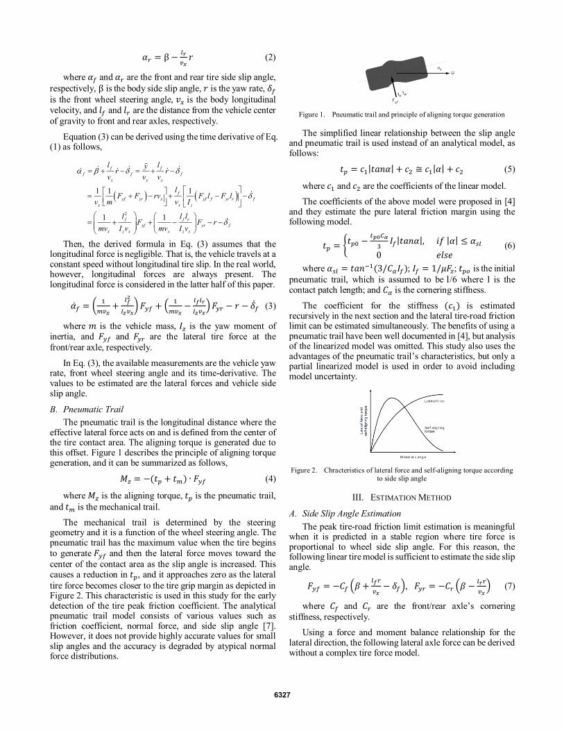
B. Pneumatic Trail
The pneumatic trail is the longitudinal distance where the effective lateral force acts on and is defined from the center of the tire contact area. The aligning torque is generated due to this offset. Figure 1 describes the principle of aligning torque generation, and it can be summarized as follows,
𝑀𝑧 = −(𝑡𝑝 + 𝑡𝑚) ∙ 𝐹𝑦𝑓 (4)
where 𝑀𝑧 is the aligning torque, 𝑡𝑝 is the pneumatic trail,
and 𝑡𝑚 is the mechanical trail.
The mechanical trail is determined by the steering geometry and it is a function of the wheel steering angle. The pneumatic trail has the maximum value when the tire begins
to generate 𝐹𝑦𝑓 and then the lateral force moves toward the
center of the contact area as the slip angle is increased. This causes a reduction in 𝑡𝑝, and it approaches zero as the lateral
tire force becomes closer to the tire grip margin as depicted in Figure 2. This characteristic is used in this study for the early detection of the tire peak friction coefficient. The analytical pneumatic trail model consists of various values such as friction coefficient, normal force, and side slip angle [7]. However, it does not provide highly accurate values for small slip angles and the accuracy is degraded by atypical normal force distributions.
Figure 1. Pneumatic trail and principle of aligning torque generation
The simplified linear relationship between the slip angle and pneumatic trail is used instead of an analytical model, as follows:
𝑡𝑝 = 𝑐1|𝑡𝑎𝑛𝛼| + 𝑐2 ≅ 𝑐1|𝛼| + 𝑐2 (5)
where 𝑐1 and 𝑐2 are the coefficients of the linear model.
The coefficients of the above model were proposed in [4] and they estimate the pure lateral friction margin using the following model.
𝑡𝑝 = {𝑡𝑝0 −𝑡𝑝0𝐶𝛼
3𝐼𝑓|𝑡𝑎𝑛𝛼|, 𝑖𝑓 |𝛼| ≤ 𝛼𝑠𝑙
0 𝑒𝑙𝑠𝑒 (6)
where 𝛼𝑠𝑙 = 𝑡𝑎𝑛−1(3/𝐶𝛼𝐼𝑓); 𝐼𝑓 = 1/𝜇𝐹𝑧; 𝑡𝑝𝑜 is the initial
pneumatic trail, which is assumed to be l/6 where l is the contact patch length; and 𝐶𝛼 is the cornering stiffness.
The coefficient for the stiffness (𝑐1) is estimated recursively in the next section and the lateral tire-road friction limit can be estimated simultaneously. The benefits of using a pneumatic trail have been well documented in [4], but analysis of the linearized model was omitted. This study also uses the advantages of the pneumatic trail’s characteristics, but only a partial linearized model is used in order to avoid including model uncertainty.
Figure 2. Chracteristics of lateral force and self-aligning torque according to side slip angle
III. ESTIMATION METHOD
A. Side Slip Angle Estimation
The peak tire-road friction limit estimation is meaningful when it is predicted in a stable region where tire force is proportional to wheel side slip angle. For this reason, the following linear tire model is sufficient to estimate the side slip angle.
𝐹𝑦𝑓 = −𝐶𝑓 (𝛽 +𝑙𝑓𝑟
𝑣𝑥− 𝛿𝑓), 𝐹𝑦𝑟 = −𝐶𝑟 (𝛽 −
𝑙𝑟𝑟
𝑣𝑥) (7)
where 𝐶𝑓 and 𝐶𝑟 are the front/rear axle’s cornering
stiffness, respectively.
Using a force and moment balance relationship for the lateral direction, the following lateral axle force can be derived without a complex tire force model.
6327

�̂�𝑦𝑓 =𝑚𝑙𝑟𝑎𝑦+𝐼𝑧�̇�
𝑙𝑓+𝑙𝑟, �̂�𝑦𝑟 =
𝑚𝑙𝑓𝑎𝑦−𝐼𝑧�̇�
𝑙𝑓+𝑙𝑟 (8)
where 𝑎𝑦 is the lateral acceleration and �̇� is the yaw
acceleration, which comes from the yaw rate sensor.
Substituting Eq. (8) into Eq. (3), the following open-loop observer can be designed.
�̇̂�𝑓 = (1
𝑚𝑣𝑥+
𝑙𝑓2
𝐼𝑧𝑣𝑥) �̂�𝑦𝑓 + (
1
𝑚𝑣𝑥−
𝑙𝑓𝑙𝑟
𝐼𝑧𝑣𝑥) �̂�𝑦𝑟 − 𝑟 − �̇�𝑓 (9)
The estimated 𝛼𝑟 can also be represented as follows with an estimate of the above �̂�𝑓.
�̂�𝑟 = �̂�𝑓 −𝑙𝑓+𝑙𝑟
𝑣𝑥𝑟 + 𝛿𝑓 (10)
The ultimate goal of the tire-road friction coefficient estimation is to provide an accurate potential friction limit to the vehicle controller unit (VCU). That is, when the current vehicle state is about to move beyond the stable area in a mu-slip curve, the active safety control systems such as the ESC are activated in order to recover the vehicle to its original position. Early detection of the maximum tire-road friction limit is important in determining whether the control system of the vehicle activates or not; therefore, the linear region is significantly more important than remainder of the mu-slip
curve in Figure 2. Thus, the open-loop observer for 𝛼𝑓 only
considers the stable area that is sufficient to achieve the goal of this study. Cornering stiffness is a function of normal tire force, in the following equation [11]. The area that exhibits nonlinear characteristics is not in the scope of this paper, so the cornering stiffness adaptation [12] is not be performed.
𝐶𝛼 = a𝐹𝑧 − 𝑏𝐹𝑧2 (11)
where a and b are the constant coefficients.
B. Tire-Road Friction Coefficient Estimation Method
The primary assumption made in this section is that the vehicle travels at a constant speed, i.e. a pure side slip condition, and thus there is no longitudinal tire slip. Figure 3 describes how the proposed normalized and linearized pneumatic trail model in Eq. (6) is changed according to the wheel side slip angle with a constant 𝐶𝛼 and 𝐹𝑧 (𝐶𝛼 = 90,000 N/rad, 𝐹𝑧 = 10,000 N/rad). The pneumatic trail has a distinguishable stiffness according to the different road surface conditions.
Figure 3. Plot of linearized pneumatic trail model.
Unlike previous works [4, 13], a partial linearized pneumatic trail model is used in this study in order to avoid
including model uncertainty. Dividing both sides by 𝑡𝑝0 in Eq.
(6), the stiffness in Figure 3 can be written as follows.
m̂ = −𝐶𝛼𝐼𝑓
3= −
𝐶𝛼
3𝜇𝐹𝑧 (12)
The nominal stiffness for each road surface was –3 (mu = 1.0), –4.28 (mu = 0.7), –6 (mu = 0.5), and –10 (mu = 0.2).
The recursive least squares (RLS) algorithm is used to estimate the stiffness iteratively through minimizing the weighted linear least squares cost function. The algebraic manipulation of Eq. (6) is performed in order to apply the RLS algorithm as follows.
𝑡𝑝
𝑡𝑝0− 1 = −
𝐶𝛼
3𝜇𝐹𝑧|𝑡𝑎𝑛𝛼| ≈ −�̂�𝛼 (13)
The available values are 𝑡𝑝/𝑡𝑝0 and 𝛼 from the previous
estimation results. 𝐶𝛼 is assumed to have a constant value because the tire stays in the stable region where it exhibits a linear property. 𝐹𝑧 can be easily estimated without considering the road slope angle as follows.
𝐹𝑧𝑓 =𝑚𝑔𝑙𝑟−𝑚𝑎𝑥ℎ
𝑙𝑓+𝑙𝑟 , 𝐹𝑧𝑟 =
𝑚𝑔𝑙𝑓+𝑚𝑎𝑥ℎ
𝑙𝑓+𝑙𝑟 (14)
where ℎ is the vehicle’s height of center of gravity, 𝐹𝑧𝑓
and 𝐹𝑧𝑟 are the front/rear axle’s normal forces, respectively, and 𝑎𝑥 is the longitudinal acceleration.
Equation (13) can be rewritten into a standard RLS algorithm format as follows.
y(k) = ∅𝑇(𝑘)𝜃(𝑘) + 𝑒(𝑘) (15)
where y(k) =(𝑡𝑝/𝑡𝑝0 − 1) is the system output, θ(k) =�̂� is the unknown parameter, ∅𝑇(𝑘) = 𝛼 is the measured regression vector, and 𝑒(𝑘) is the identification error.
The specific procedures for the RLS algorithm at each time step k are as follows:
1. Calculate the identification error:
e(k) = y(k) − ∅𝑇(𝑘)𝜃(𝑘) (16)
2. Calculate the updated gain vector:
K(k) =𝑃(𝑘−1)∅(𝑘)∅𝑇(𝑘)𝑃(𝑘−1)
𝜆+∅𝑇(𝑘)𝑃(𝑘−1)∅(𝑘) (17)
3. Calculate the covariance matrix:
P(k) =1
𝜆[𝑃(𝑘 − 1) −
𝑃(𝑘−1)∅(𝑘)∅𝑇(𝑘)𝑃(𝑘−1)
𝜆+∅𝑇(𝑘)𝑃(𝑘−1)∅(𝑘)] (18)
4. Update the parameter estimate vector:
θ̂(k) = θ̂(k − 1) + 𝐾(𝑘)𝑒(𝑘) (19)
where 𝜆 is the forgetting factor that is used to reduce the influence of the old data and it typically has a value in [0.9,1].
In this way, the maximum tire-road friction limit can be derived using the stiffness estimated in Eq. (12). This paper only uses the stiffness as a source of estimation and use of the full pneumatic trail model is discouraged because the analysis of the full model is insufficient for atypical road surfaces. The various parameters such as normal force, slip angle, and longitudinal force can affect the form of the pneumatic trail due to the tire’s strong nonlinear characteristics as in Eq. (20).
𝑡𝑝 = 𝑓(𝛼, 𝐹𝑧 , 𝐹𝑥 … … ) (20)
6328

The practical pneumatic trail is difficult to model accurately, but it has a different reduced speed according to the road surface, which can be seen from the experimental data. This is why only the stiffness according to the road surface is used in the linearized model in Eq. (6). In addition, incorrect estimates of lateral force and side slip angle can adversely affect the estimation of the tire-road friction limits when the entire model is accepted without modification.
C. Correction Factor based on Accelerations
The proposed algorithm that assumes pure side slip becomes invalid when an excessive longitudinal force is included. Because the pneumatic trail is easily affected by the longitudinal force and its stiffness demonstrates that different aspect in Figure 3. Therefore, the primary assumption that a vehicle travels at a constant speed is identical to the previous works, but the correction factor that can allow some longitudinal dynamics coupled with lateral dynamics is introduced in this section.
In the real world, the longitudinal force generation in the tire is inevitable even though the vehicle travels at almost a constant speed. If the longitudinal force is added to the proposed algorithm as depicted in Figure 4, the estimation result might be underestimated due to the coupling effect between the longitudinal force and lateral force. That is, the proposed algorithm assumes that the peak tire road friction is dominated by the lateral tire force, but only partial longitudinal force contributes the formation of the friction coefficient.
Figure 4. Coupling effect of longitudinal force and lateral force
The following heuristic rule is created in order to allow some longitudinal force in the estimation result.
where 𝑘 is the correction factor, μ̂ is the estimated friction coefficient from the previous section, 𝜇 is the corrected friction coefficient, 𝑎𝑥 and 𝑎𝑦 are the longitudinal/lateral
acceleration at the center of gravity of vehicle, respectively, and α is the arbitrary constant value that is proportional to 𝑎𝑥/𝑎𝑦, which can be determined from the trial and error.
If the ratio of the longitudinal acceleration to the lateral acceleration is less than 5%, then the longitudinal intervention level can be neglected; thus, the correction factor is assumed to be zero. However, provided that 𝑎𝑥/𝑎𝑦 is in the range of
[0.05, 0.2], the correction factor should be determined in order
to allow some longitudinal dynamics. The heuristic correction factor is determined using a constant value ( α ) that is proportional to 𝑎𝑥/𝑎𝑦. The proposed algorithm does not have
an effect with a relatively large 𝑎𝑥/𝑎𝑦 of more than 20%. The
pneumatic trail model should be modified in this excessive longitudinal dynamics through including the longitudinal tire slip.
IV. SIMULATION AND EXPERIMENT RESULTS
A. Simulations
In order to illustrate the performance of the developed algorithm, a simulation using Carsim was conducted. The vehicle used in the simulation was a D-class sedan stored in Carsim and the tire was modeled using a magic formula. A slalom maneuver was performed in order to give an excitation signal to the proposed algorithm, as depicted in Figure 5; the vehicle speed was assumed to be constant at approximately 90 km/h. In order to evaluate the convergence rate at the transient area, the mu-transition occurred twice after the homogenous road surface.
In the linear region of the mu-slip curve, the open-loop observer for the wheel side slip angle tracked the actual values well as illustrated in Figure 5, even though abrupt mu-transitions occurred at 20 s and 40 s. From this, it is determined that the axle lateral forces are not affected by the road surface conditions. The estimation result presented in Figure 6 demonstrates that the pneumatic trail stiffness based estimation algorithm can identify the peak tire-road friction coefficient in the early stages. Moreover, the current mu (induced from the coulomb friction) is insufficient to predict the potential friction coefficient that is a crucial factor in the vehicle control system. As depicted in Figure 6, the current mu from the Carsim signal was significantly lower than the actual value, but the estimated friction coefficient from the proposed algorithm could track the true value in most areas. The current mu had a similar value on different road surfaces because there was no significant curve shape change in the low slip region. That is, it was difficult distinguish between the different road surfaces for the small wheel side slip angle that necessitates the usage of the pneumatic trail’s benefits.
Figure 5. Plot of simulation maneuver and wheel side slip angle eistmation
result.
ˆ
0 , 0.05
/ , 0.05 0.2
undefined (combinedslip) , 0.2
x
y
xx y
y
x
y
k
where
ak
a
ak a a
a
ak
a
6329

In contrast, the model-based methods from previous studies can lose effectiveness due to rapid steering maneuvers. That is, the estimation results cannot converge to a constant value because the model-based estimation depends on the linearized pneumatic trail model, which reacts sensitively to excitation signals. This shortcoming necessitates the use of the forgetting factor in order to provide more weight to the recent data than old data. The primary role of the forgetting factor is to prevent the divergence of the estimation results, but a time delay exists. Traditionally, there is a trade-off between the convergence rate performance and sensitivity. For example, if a relatively large forgetting factor (λ = 1) is used, then the estimation result cannot converge to a constant value because all data is given the same weight. Therefore, λ = 0.995 is used in this simulation in order to prevent this divergence.
Figure 6. Plot of tire force and friction coefficient estimation results (mu-transition)
B. Experiments
In order to demonstrate the possibility of implementing the proposed algorithm in a commercial vehicle, an experiment was conducted on a proving ground. The test vehicle traveled on a proving ground paved with dry asphalt and the excitation signal was a sine sweep maneuver as depicted in Figure 8. The wheel force transducer sensor that can measure the individual tire forces and moments was used to measure the aligning torque. Accurate estimation of the aligning torque is beyond the scope of this paper; therefore, direct measurement from the sensor was used instead of the assist motor torque in the EPS. The disturbance observer used to estimate the self-aligning torque was proposed previously and it has been well documented in [8].
Figure 7 describes the configuration of the test vehicle equipped with the wheel force transducer. The other necessary signals, e.g. accelerations, gyroscope measurements and wheel steering angles, were obtained using the Can Bus signal in real-time. The test vehicle was driven at an almost constant speed of approximately 80 km/h, but the longitudinal force appeared to be significantly larger than that of the simulation. This resulted from the engine throttle control occurring constantly
when the driver pressed the pedal shift. Therefore, the presence of the longitudinal slip cannot be avoided in actual driving. In addition, a perfectly constant velocity such as in the Carsim simulation cannot be achieved by a human driver. Considering the practical usage of the proposed algorithm, the inclusion of longitudinal force is necessary in order to present a more reasonable estimation result. Although the combined slip, which refers to the relatively large longitudinal slip being included, is not considered in this paper, the intervention level of the longitudinal force due to the acceleration or deceleration is considered using a correction factor.
Figure 7. Test vehicle : full size SUV equipped with wheel force transducer
Figure 8 presents the experiment maneuver and wheel side slip angle estimation results. In general, a sine sweep was used to evaluate the vehicle’s handling performance in various frequency domains, and it also generated the pneumatic trail in this experimental validation. As in the simulation, the tire remained in the linear region in the mu-slip curve; thus, the estimation of the wheel side slip angles matched well with the actual values in all areas as depicted in Figure 8.
Figure 8. Plot of experimental maneuver and wheel side slip angle eistmation result.
The lumped lateral force in both the front and rear axle was also well estimated as seen in Figure 9. However, the aligning torque measurement from the wheel force transducer was not robust to sensor noise, and therefore signal filtering was performed in order to suppress the divergent measurements.
6330

The selected filter was the rate limiter that limited the slope of the raw data without phase lag.
As depicted in Figure 9, the model-based estimation result cannot provide a meaningful value due to its highly sensitive responsiveness to the excitation signal. The use of the forgetting factor enabled it to converge in [0.8, 0.9]. The currently used friction coefficient remained in [0.2, 0.3], but the estimated value was significantly higher. This means that early detection of the maximum friction limit was enabled using the pneumatic trail stiffness characteristics. As in the simulation results, the convergence rate performance was degraded using the forgetting factor; thus, the estimation results converged to the true value after 5 s. If a relatively large forgetting factor was used, then the estimation result might exhibit oscillation as in the model-based method.
Figure 9. Plot of tire force and friction coefficient estimation results
A key feature of this experiment is that highly accurate extraction of aligning torque is essential in this algorithm. Because the pneumatic trail is defined as in Eq. (4), it can be easily affected by estimation errors in the aligning torque.
The wheel force transducer used in this study provided an error rate of less than 1%, but when it was converted to a physical value, the possible error was in the range of [–45 N, +45 N], which cannot be neglected when computing the accurate pneumatic trail. For this reason, a more accurate method to measure or estimate the aligning torque is required in order to maintain the algorithm’s robustness against signal noise. However, this is not within the scope of the paper, so future work should include a method for estimating the aligning torque from the assist motor torque in the EPS. In addition, more analytic linearized pneumatic trail models should be proposed through considering the physical aspects. Because the practical linearized model suggested in [8] is not fully verified for various road surface conditions, future work should also consider the design of a pneumatic trail model that includes the primary parameters such as 𝐶𝛼, 𝐹𝑧, and α.
V. CONCLUSION
This paper presented a method that estimates the tire-road
friction limit based on the pneumatic trail stiffness. In order to
avoid model uncertainty, part of the linearized pneumatic trail
model was used. The simulation and experiment results
revealed that the pneumatic trail stiffness could be used to
identify the friction limit in the linear region and it is more
robust to model uncertainty than the conventional method.
Unlike previous works, the intervention level of the
longitudinal force was also reflected using the accelerations at
the vehicle’s center of gravity. The feasibility of the proposed
method is increased when considering actual human driver
characteristics. However, highly accurate estimations of
aligning the torque are required in order to maintain the
proposed method’s robustness against signal noise. Therefore,
future work should include a method of accurately estimating
the aligning torque and more tests are required in order to
evaluate the robustness of the algorithm against various road
surfaces.
ACKNOWLEDGMENT
This research was supported by the MSIP (Ministry of
Science, ICT and Future Planning), Korea, under the C-ITRC
(Convergence Information Technology Research Center)
(IITP-2015-H8601-15-1005) supervised by the IITP (Institute
for Information & Communications Technology Promotion)
and this work was supported by the National Research
Foundation of Korea (NRF) grant funded by the Korea
government (2010-0028680).
REFERENCES
[1] M. Choi, J. J. Oh, and S. B. Choi, "Linearized recursive least squares
methods for real-time identification of tire–road friction coefficient,"
Vehicular Technology, IEEE Transactions on, vol. 62, pp. 2906-2918,
2013.
[2] J. J. Oh and S. B. Choi, "Vehicle velocity observer design using 6-d imu
and multiple-observer approach," Intelligent Transportation Systems,
IEEE Transactions on, vol. 13, pp. 1865-1879, 2012.
[3] R. Rajamani, G. Phanomchoeng, D. Piyabongkarn, and J. Y. Lew,
"Algorithms for real-time estimation of individual wheel tire-road friction
coefficients," Mechatronics, IEEE/ASME Transactions on, vol. 17, pp.
1183-1195, 2012.
[4] Y.-H. J. Hsu, S. M. Laws, and J. C. Gerdes, "Estimation of tire slip angle
and friction limits using steering torque," Control Systems Technology,
IEEE Transactions on, vol. 18, pp. 896-907, 2010.
[5] K. Nakajima, M. Kurishige, M. Endo, and T. Kifuku, "A vehicle state
detection method based on estimated aligning torque using EPS," SAE
Technical Paper 0148-7191, 2005.
[6] C. Ahn, H. Peng, and H. E. Tseng, "Robust estimation of road frictional
coefficient," Control Systems Technology, IEEE Transactions on, vol. 21,
pp. 1-13, 2013.
[7] H. Pacejka, Tire and vehicle dynamics: Elsevier, 2005.
[8] Y.-H. J. Hsu, Estimation and control of lateral tire forces using steering
torque: ProQuest, 2009.
[9] D. Simon, Optimal state estimation: Kalman, H infinity, and nonlinear
approaches: John Wiley & Sons, 2006.
[10] R. Rajamani, Vehicle dynamics and control: Springer Science &
Business Media, 2011.
[11] M. Doumiati, A. C. Victorino, A. Charara, and D. Lechner, "Onboard
real-time estimation of vehicle lateral tire–road forces and sideslip
angle," Mechatronics, IEEE/ASME Transactions on, vol. 16, pp. 601-614,
2011.
[12] C. Sierra, E. Tseng, A. Jain, and H. Peng, "Cornering stiffness estimation
based on vehicle lateral dynamics," Vehicle System Dynamics, vol. 44,
pp. 24-38, 2006.
[13] S. Song, M. C. K. Chun, J. Huissoon, and S. L. Waslander, "Pneumatic
trail based slip angle observer with Dugoff tire model," in Intelligent
Vehicles Symposium Proceedings, 2014 IEEE, 2014, pp. 1127-1132.
6331