l 95 bike (std-7607) 95 bike use and...-safety of lifted vehicles the company is not liable for...
TRANSCRIPT

LIFTING PLATFORM
USE AND MAINTENANCE MANUAL UK
L 95 BIKE (STD-7607)


REV. 01 2012 2 / 29
PRINTING CHARACTERS AND SYMBOLS
Throughout this manual, the following symbols and printing characters are used to facilitate reading:
Indicates the operations which need proper care
Indicates prohibition
Indicates a possibility of danger for the operators
Indicates the direction of access for motor vehicles to the lift
BOLD TYPE Important information
WARNING: before operating the lift and carrying out any adjustment, read carefully chapter 7 “installation” where all proper operations for a better functioning of the lift are shown.

REV. 01 2012 3 / 29
CONTENTS
1 GENERAL INFORMATION 4
2 PRODUCT IDENTIFICATION 6
3 PACKING, TRANSPORT AND STORAGE 7
4 PRODUCT DESCRIPTION 9
5 TECHNICAL SPECIFICATION 11
6 SAFETY 17
7 INSTALLATION 20
8 OPERATION AND USE 25
9 MAINTENANCE 28
10 TROUBLESHOOTING 29

REV. 01 2012 4 / 29
CHAPTER 1 – GENERAL INFORMATION
This chapter contains warning instructions to operate the lift properly and prevent injury to operators or objects. This manual has been written to be used by shop technicians in charge of the lift (operator) and routine maintenance technician (maintenance operator). The operating instructions are considered to be an integral part of the machine and must remain with it for its whole useful life. Read every section of this manual carefully before operating the lift and unpacking it since it gives helpful information about: - SAFETY OF PEOPLE - SAFETY OF THE LIFT - SAFETY OF LIFTED VEHICLES The company is not liable for possible problems, damage, accidents, etc. resulting from failure to follow the instructions contained in this manual.
Only skilled technicians of AUTHORISED DEALERS or SERVICE CENTRES AUTHORISED by the manufacturer shall be allowed to carry out lifting, transport, assembling, installation, adjustment, calibration, settings, extraordinary maintenance, repairs, overhauling and dismantling of the lift. THE MANUFACTURER IS NOT RESPONSIBLE FOR POSSIBLE DAMAGE TO PEOPLE, VEHICLES OROBJECTS IF SAID OPERATIONS ARE CARRIED OUT BY UNAUTHORIZED PERSONNEL OR THE LIFT IS IMPROPERLY USED. Any use of the machine made by operators who are not familiar with the instructions and procedures contained herein shall be forbidden.
1.1 MANUAL KEEPING
For a proper use of this manual, the following is recommended: • keep the manual near the lift, in an easily accessible place• keep the manual in an area protected from the damp• use this manual properly without damaging it.• Any use of the machine made by operators who are not familiar with the instructions and
procedures contained herein shall be forbidden.
This manual is an integral part of the lift: it shall be given to the new owner if and when the lift is resold
1.2 OBLIGATION IN CASE OF MALFUNCTION
In case of machine malfunction, follow the instructions contained in the following chapters.
1.3 CAUTIONS FOR THE SAFETY OF THE OPERATOR
Operators must not be under the influence of sedatives, drugs or alcohol when operating the machine.

REV. 01 2012 5 / 29
Before operating the lift, operators must be familiar with the position and function of all controls, as well as with the machine features shown in the chapter “Operation and use”
1.4 WARNINGS
Unauthorized changes and/or modifications to the machine relieve the manufacturer of any liability for possible damages to objects or people. Do not remove or make inoperative the safety devices, this would cause a violation of safety at work laws and regulations.
Any other use which differs from that provided for by the manufacturer of the machine is strictly forbidden.
The use of non genuine parts may cause damage to people or objects
DECLARATION OF WARRANTY AND LIMITATION OF LIABILITY
The manufacturer has paid proper attention to the preparation of this manual. However, nothing contained herein modifies or alters, in any way, the terms and conditions of manufacturer agreement by which this lift was acquired, nor increase, in any way, manufacturer’s liability to the customer.
TO THE READER
Every effort has been made to ensure that the information contained in this manual is correct, complete and up-to date. The manufacturer is not liable for any mistakes made when drawing up this manual and reserves the right to make any changes due the development of the product, at any time.
REV. 01 2012 6 / 29
CHAPTER 2 – PRODUCT IDENTIFICATION
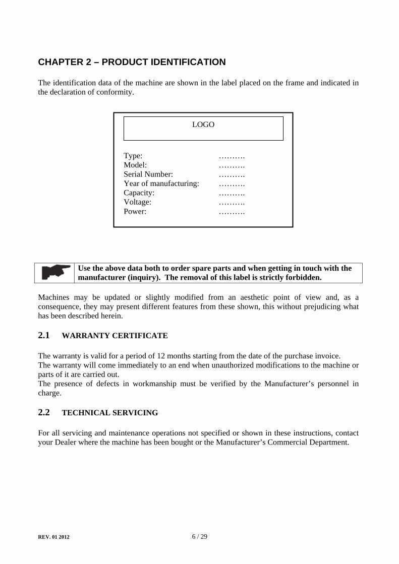
The identification data of the machine are shown in the label placed on the frame and indicated in the declaration of conformity.
Use the above data both to order spare parts and when getting in touch with the manufacturer (inquiry). The removal of this label is strictly forbidden.
Machines may be updated or slightly modified from an aesthetic point of view and, as a consequence, they may present different features from these shown, this without prejudicing what has been described herein.
2.1 WARRANTY CERTIFICATE
The warranty is valid for a period of 12 months starting from the date of the purchase invoice. The warranty will come immediately to an end when unauthorized modifications to the machine or parts of it are carried out. The presence of defects in workmanship must be verified by the Manufacturer’s personnel in charge.
2.2 TECHNICAL SERVICING
For all servicing and maintenance operations not specified or shown in these instructions, contact your Dealer where the machine has been bought or the Manufacturer’s Commercial Department.
LOGO
Type: ………. Model: ………. Serial Number: ………. Year of manufacturing: ………. Capacity: ………. Voltage: ………. Power: ……….

REV. 01 2012 7 / 29
CHAPTER 3 - PACKING, TRANSPORT AND STORAGE
Only skilled personnel who are familiar with the lift and this manual shall be allowed to carry out packing, lifting, handling, transport and unpacking operations.
3.1 PACKING
The lift is delivered in many components that appears sub-assembled. The lay-out is referred to the model. In ground model
• No. 1 base units with a platform and hydraulic cylinders• No. 1 pneumatic pedal pump
If requested, optional accessories are available to satisfy each customer’s requirements (Ref. accessories manual and price lists) The lift is packed in a single box on a wooden bed, wrapped up in non-scratch waterproof material and sealed with 2 straps. The average weight of the package is 200 kg
3.2 LIFTING AND HANDLING
When loading/unloading or transporting the equipment to the site, be sure to use suitable loading (e.g. cranes, trucks) and hoisting means. Be sure also to hoist and transport the components securely so that they cannot drop, taking into consideration the package’s size, weight and centre of gravity and it’s fragile parts.
Figure 1 – PACKAGE AND HANDLING
Hoist and handle only one package at a time
3.3 STORAGE AND STACKING OF PACKAGES
Packages must be stored in a covered place, out of direct sunlight and in low humidity, at a temperature between -10°C and +40°C. Stacking is not recommended: the package’s narrow base, as well as its considerable weight and size make it difficult and hazardous.

REV. 01 2012 8 / 29
3.4 DELIVERY AND CHECK OF PACKAGES
When the lift is delivered, check for possible damages due to transport and storage; verify that what is specified in the manufacturer’s confirmation of order is included. In case of damage in transit, the customer must immediately inform the carrier of the problem. Packages must be opened paying attention not to cause damage to people (keep a safe distance when opening straps) and parts of the lift (be careful the objects do not drop from the package when opening).
REV. 01 2012 9 / 29
CHAPTER 4 - PRODUCT DESCRIPTION
4.1 LIFT (rif. figure 2)
The lift has been designed to lift motorcycles and make them stand at any level between the minimum and maximum height.. The maximum lifting weight, including any additional load on the vehicle, is as specified on the serial plate All mechanical frames, such as platforms, extensions, base frames and arms have been built in steel plate to make the frame stiff and strong while keeping a low weight The operation is described in detail in chapter 8.
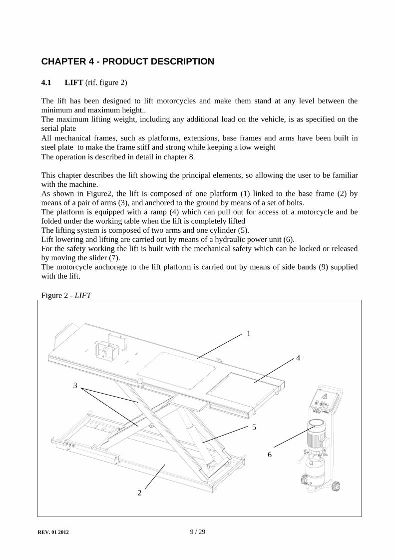
This chapter describes the lift showing the principal elements, so allowing the user to be familiar with the machine. As shown in Figure2, the lift is composed of one platform (1) linked to the base frame (2) by means of a pair of arms (3), and anchored to the ground by means of a set of bolts. The platform is equipped with a ramp (4) which can pull out for access of a motorcycle and be folded under the working table when the lift is completely liftedThe lifting system is composed of two arms and one cylinder (5). Lift lowering and lifting are carried out by means of a hydraulic power unit (6). For the safety working the lift is built with the mechanical safety which can be locked or released by moving the slider (7). The motorcycle anchorage to the lift platform is carried out by means of side bands (9) supplied with the lift.
Figure 2 - LIFT
1
2
4
3
6
5

REV. 01 2012 10 / 29
4.2 OPERATION
Before carrying out any operation, secure the motorcycle to the platform by means of the specially provided clamping straps The motorcycle lifting with the straps not properly secured or without straps at all is strictly forbidden
Platform lifting is carried out by the air-hydraulic pump which acts upon the cylinder. The hydraulic system is protected by a max. pressure control valve in the air-hydraulic pump preventing the pressure from exceeding the maximum fixed safety limit Lifting/lowering motion of the lift is controlled by the panel placed on the air-hydraulic pump. The mechanical safety prevents the runway from accidental or uncontrolled lowering in case of hydraulic system malfunction or leakage in the hydraulic circuit hose. Lowering is carried out by the weight of both the platform and the load lifted.
7
REV. 01 2012 11 / 29
CHAPTER 5 - TECHNICAL SPECIFICATION
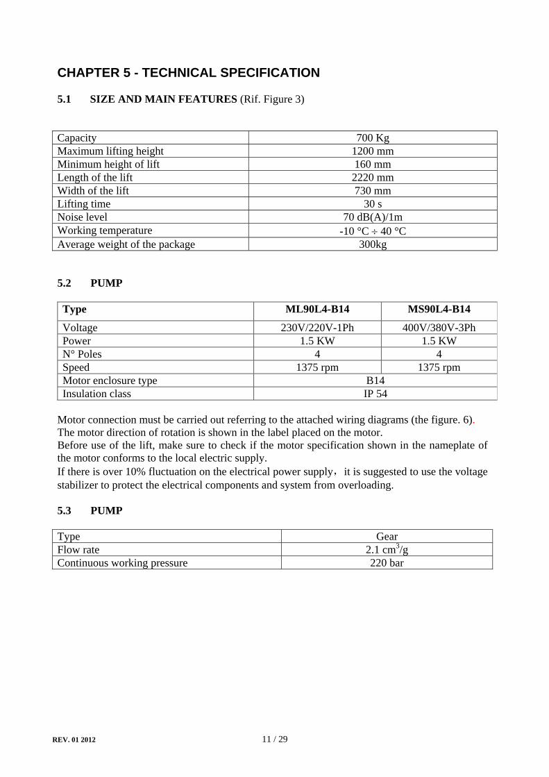
5.1 SIZE AND MAIN FEATURES (Rif. Figure 3)
Capacity 700 KgMaximum lifting height 1200 mm Minimum height of lift 160 mm Length of the lift 2220 mm Width of the lift 730 mm Lifting time 30 s Noise level 70 dB(A)/1m Working temperature -10 °C ÷ 40 °C Average weight of the package 300kg
5.2 PUMP
Type ML90L4-B14 MS90L4-B14
Voltage 230V/220V-1Ph 400V/380V-3Ph Power 1.5 KW 1.5 KW N° Poles 4 4 Speed 1375 rpm 1375 rpm Motor enclosure type B14 Insulation class IP 54
Motor connection must be carried out referring to the attached wiring diagrams (the figure. 6). The motor direction of rotation is shown in the label placed on the motor. Before use of the lift, make sure to check if the motor specification shown in the nameplate of the motor conforms to the local electric supply. If there is over 10% fluctuation on the electrical power supply,it is suggested to use the voltage stabilizer to protect the electrical components and system from overloading.
5.3 PUMP
Type Gear Flow rate 2.1 cm3/g Continuous working pressure 220 bar

REV. 01 2012 12 / 29
Figure 3 – LAYOUT

REV. 01 2012 13 / 29
5.4 HYDRAULIC POWER UNIT
The power unit is equipped with
Figure 4 – HYDRAULIC POWER UNIT
5.5 OIL
Use wear proof oil for hydraulic drive, in conformity with ISO 6743/4 rules (HM class). The oil with features similar to those shown in the table is recommended.
TEST STANDARDS FEATURES VALUE ASTM D 1298 Density 20°C 0.8 kg/l ASTM D 445 Viscosity 40°C 32 cSt ASTM D 445 Viscosity 100°C 5.43 cSt ASTM D 2270 Viscosity index 104 N° ASTM D 97 Pour point ∼ 30 °CASTM D 92 Flash point 215 °C ASTM D 644 Neutralization number 0.5 mg KOH/g
CHANGE HYDRAULIC OIL AT 1 YEAR INTERVALS
Motor
Maximum pressure valve
Lowering valve
Lowering handle
Oil level plug Oil tank

REV. 01 2012 14 / 29
Figure 5 - HYDRAULIC PLAN
1 Hydraulic cylinder 5 Gear pump 2 Safety valve (flow restrictor) 6 Oil filter 3 Non return valve 7 Motor 4 Maximum pressure valve 8 Manual lowering valve

REV. 01 2012 15 / 29
Figure 6a – ELECTRICAL DIAGRAM (380V/400V - 3PH)
FU1-3
3 x black1 x green/yellow
W
3
red
black
3 x black1 x green/yellow
QF Power switch T Transformer 63VA KM Contactor AC SB Lifting pushbutton ST Thermal relay M Motor 1.5KW 3PH
REV. 01 2012 16 / 29
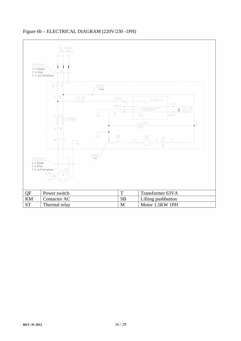
Figure 6b – ELECTRICAL DIAGRAM (220V/230 -1PH)
1 x black1 x blue1 x yellow/green
3
red
black
1 x black1 x blue
1 x yellow/green
QF Power switch T Transformer 63VA KM Contactor AC SB Lifting pushbutton ST Thermal relay M Motor 1.5KW 1PH

REV. 01 2012 17 / 29
CHAPTER 6 - SAFETY
Read this chapter carefully and completely because it contains important information for the safety of the operator and the person in charge of maintenance
The lift has been designed and built for lifting vehicles and making them stand above level in a closed area. any other use is forbidden. the manufacturer is not liable for possible damages to people, vehicles or objects resulting from an improper or unauthorized use of the lift.
For operator and people safety, the safety area shown in Figure 5 must be vacated during lifting and lowering. The lift must be operated only from the operator’s control site, as shown. Operator’s presence under the vehicle, during working, is only admitted when the vehicle is lifted and platforms are not running
Ever use the lift when safety devices are off-line. people, the lift and the vehicles lifted can be seriously damaged if these instructions are not followed.
Figure 7 - SAFETY AREA
SAFETY AREA (min. 1 meter)
6.1 GENERAL WARNINGS
The operator and the person in charge of maintenance must follow accident-prevention laws and rules in force in the country where the lift is installed They also must carry out the following:
• neither remove nor disconnect hydraulic, electric or other safety devices;• carefully follow the safety indications applied on the machine and included in the manual;• observe the safety area during lifting;• be sure the motor of the vehicle is off, the gear engaged and the parking brake put on;

REV. 01 2012 18 / 29
• be sure only authorized vehicles are lifted without exceeding the maximum lifting capacity;• verify that no one is on the platforms during lifting or standing.
6.2 RISKS DURING VEHICLE LIFTING
To avoid overloading and possible breaking, the following safety devices have been used: • a maximum pressure valve placed inside the hydraulic unit to prevent excessive weight.• a special design of the hydraulic system, in case of pipeline failure, to prevent sudden lift
lowering.
6.3 RISKS FOR PEOPLE
All risks the personnel could run, due to an improper use of the lift, are described in this section.
6.4 PERSONNEL CRUSHING RISKS
During lowering of runways and vehicles, personnel must not be within the area covered by the lowering trajectory. The operator must be sure no one is in danger before operating the lift.
6.5 BUMPING RISK
When the lift is stopped at relatively low height for working, the risk of bumping against projecting parts occurs.
6.6 RISK OF THE VEHICLE FALLING FROM THE LIFT
Vehicle falling from the lift can be caused when the vehicle is improperly placed on platforms, and when its dimensions are incompatible with the lift or by excessive movement of the vehicle. In this case, keep immediately away from the working area.

REV. 01 2012 19 / 29
6.7 SLIPPING RISKS
The risk of slipping can be caused by oil or dirt on the floor near the lift.
keep the area under and around the lift clean. Remove all oil spills
6.8 ELECTROCUTION RISKS
Avoid use of water, steam, solvent, varnish jets in the lift area where electric cables are placed and, in particular, next to the electric panel.
6.9 RISKS RESULTING FROM IMPROPER LIGHTING
Make sure all areas next to the lift are well and uniformly lit, according to local regulations.
6.10 RISKS OF BREAKING COMPONENT DURING OPERATION
Materials and procedures, suitable for the designed parameters of the lift, have been used by the manufacturer to build a safe and reliable product. Operate the lift only for the use it has been designed for and follow the maintenance schedule shown in the chapter “Maintenance”.
6.11 RISKS FOR UNAUTHORIZED USES
The presence of unauthorized persons next to the lift and on the platforms is strictly forbidden during lifting as well as when the vehicle has been already lifted
Any use of the lift other than that herein specified can cause serious accidents to people in close proximity of the machine.

REV. 01 2012 20 / 29
CHAPTER 7 - INSTALLATION
Only skilled technicians, appointed by the manufacturer, or by authorized dealers, must be allowed to carry out installation. serious damage to people and to the lift can be caused if installations are made by unskilled personnel.
Before carrying out any operations, remember to insert the safety piece of wood (1) between the lower booms and the base frame.
Figure 14 - SAFETY BLOCK
PRELIMINARY OPERATIONS 7.1 CHECKING FOR ROOM SUITABILITY The lift has been designed to be used in covered and sheltered places. The place of installation must not be next to washing areas, painting workbenches, solvent or varnish deposits. The installation near to rooms, where a dangerous situation of explosion can occur, is strictly forbidden. The relevant standards of the local Health and Safety at Work regulations, for instance, with respect to minimum distance to wall or other equipment, escapes and the like, must be observed. 7.2 LIGHTING Lighting must be carried out according to the effective regulations of the place of installation. All areas next to the lift must be well and uniformly lit. 7.3 INSTALLATION SURFACE The lift must be placed on level floor and sufficiently resistant. The surface and foundation must be suitable for bearing maximum stress values, also in unfavorable working conditions. .

REV. 01 2012 21 / 29
7.4 RUNWAY ASSEMBLY AND CONTROL DESK POSITIONING
Unauthorized persons are not allowed to enter the installation area during assembly.
• Transport platforms to the installation site by using hoisting means with load capacity of
500 kg at least • To prevent the platform from dropping during transport, it should be lifted according to its
centre of gravity.• Always raise platforms by holding them on the underside of the base frames • Position the base frames on the foundation according to the drive-on direction of the lift• Lift platforms with auxiliary equipment by using strong ropes, bands and chains and insert
the safety blocks supplied with the lift.
7.5 HYDRAULIC SYSTEM CONNECTION
• connect hydraulic hoses referring to the figure 15. • tighten fittings thoroughly.
When routing the hydraulic hose, make sure that the hose is clear of any moving part. Make sure to keep the hoses clean from dust.
Figure 15 - HYDRAULIC PIPES CONNECTION
Hydraulic cylinder
Safety valve
Hydraulic power unit
REV. 01 2012 22 / 29
7.6 MAKE THE ELECTRICAL HOOKUP TO POWER UNIT
The hookup work must be carried out by a qualified electrician.
Make sure that the power supply is right.
Make sure the connection of the phases is right. Improper electrical hook-up can damage motor and will not be covered under warranty.
The power unit must be kept dry.
• Make the electric hookup to the hydraulic unit referring to the wiring diagram figure 6 using included electric cable.
• Make sure the connection of the phases is right and the lift is grounded.
If no special request, black wires are for phases, the blue is for neutral (for single phase circuit), the yellow/green is for grounding.
7.7 STARTING
During START UP procedure, observe all operating components and check for proper installation and adjustment. DO NOT attempt to raise vehicle until a thorough operation check has been completed.
• Make sure the electrical system feeding voltage is equal to that specified in the nameplate on the motor
• Make the lift is connected to the ground • Make sure the working area is free from people and objects • Grease sliding blocks • Verify that the control unit is powered • Pour oil in the tank (about 5 liters more than one
time) • Feed the lift by the power switch • Verify that the motor direction of rotation is that
shown on the label by pushing the UP button. IF MOTOR GETS HOT OR SOUNDS PECULIAR, STOP IMMEDIATELY AND RECHECK THE ELECTRIC CONNECTIONS
• Raising the lift slowly by pressing the UP button until the lift reaches the full height. DO NOT continue pressing button after lift reaches full height. Damage to motor and the lift can occur if continued.
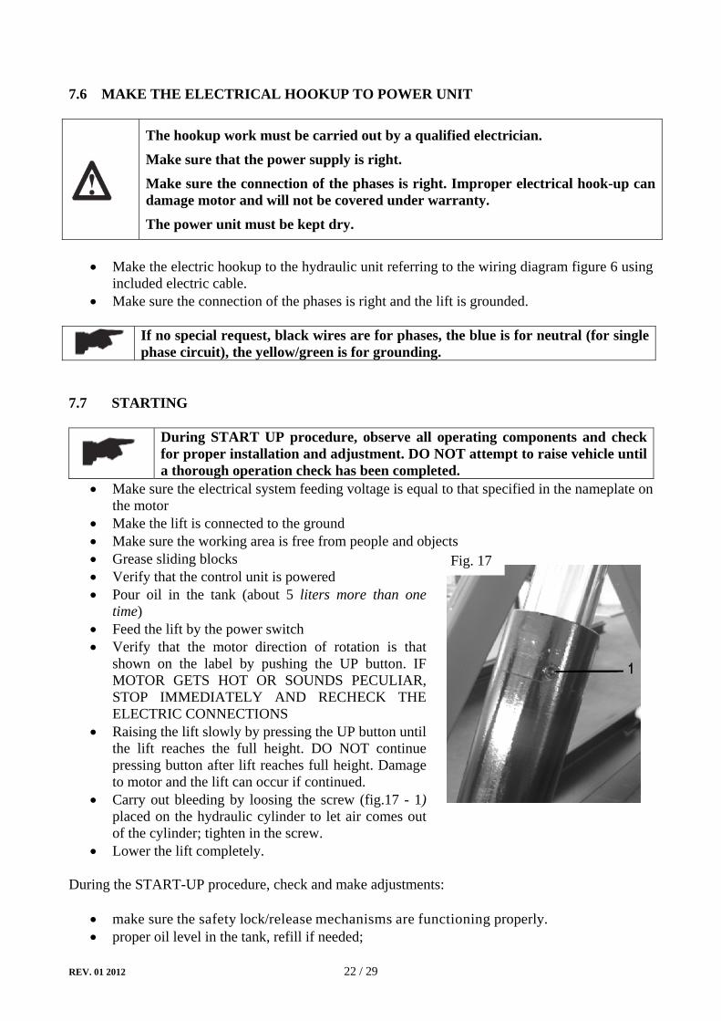
• Carry out bleeding by loosing the screw (fig.17 - 1) placed on the hydraulic cylinder to let air comes out of the cylinder; tighten in the screw.
• Lower the lift completely. During the START-UP procedure, check and make adjustments:
• make sure the safety lock/release mechanisms are functioning properly. • proper oil level in the tank, refill if needed;
Fig. 17

REV. 01 2012 23 / 29
• cylinder operation; • no leakage in hydraulic line; • the lift for reaching its maximum height;
7.7.1 MECHANICAL CHECKS
• Bolts, connectors and connections tightened. • clean all parts of the machine;
7.7.2 HYDRAULIC SYSTEM CHECK
• proper oil level in the tank • no leakage and blow-by • cylinder operation
7.8 SET UP AND ADJUSTMENTS 7.8.1 LOAD LESS CHECK Carry out two or three complete cycles of lowering and lifting and check:
• the lift for reaching its maximum height
WARNING: please follow carefully the instructions in the coming paragraph for avoiding damages on the lift.
7.8.2 CHECK WITH LOAD Carry out two or three complete cycles of lowering and lifting and check:
• the lift for reaching its maximum height • no leakage and blow-by • cylinder operation
7.8.3 BOLTS AND NUTS CHECK After carrying out the checks with load, make a visual inspection of the machine and check bolts and nuts for proper tightening. 7.8.4 MOVABLE PLATFORM ROTATION In order to operate on the motorcycle rear wheel, the drive-on ramp (1) must be inserted into the movable platform (2)
Be sure the ramp folds perfectly into its seat in a way to prevent it from falling.
Without removing the ramp (1), take out the movable platform (2) until it can rotate downwards and be perpendicular to the lift platform, then push it forward

REV. 01 2012 24 / 29
Figure 15 - MOVABLE PLATFORM ROTATION

REV. 01 2012 25 / 29
CHAPTER 8 - OPERATION AND USE
Never operate the lift with any person or equipment below.
Never exceed the rate lifting capacity.
Always ensure that the safeties are engaged before any attempt is made to work on or near the vehicle.
Never leave the lift in an elevated position unless the safeties are engaged.
If an anchor bolt becomes loose or any component of the lift is found to be defective, DO NOT USE THE LIFT until repairs are made.
8.1 CONTROLS Controls for operating the lift are: Figure 20 - CONTROLS
POWER LAMP
POWER SWITCH
POWER SWITCH (FIG. 20 - 1) The switch can be set in two positions:
0 position: the lift electric circuit is not powered; the switch can be padlocked to prevent the use of the lift.
1 position: the main electric circuit is powered LIFTING (UP) BUTTON (FIG. 20 - 2)
When pressed, the electric circuit operates the motor and hydraulic circuit to raise the lift. PLIOT LAMP (FIG. 20 - 3)
It shows that the electric circuit is powered LOWERING LEVER(FIG. 20 - 4)
When pressed, the hydraulic oil will be unloaded from the cylinder: the lift begins to lower under its weight and the load lifted.
Be sure the safety area is free from people and objects during the final travel
1
2
3 4
REV. 01 2012 26 / 29
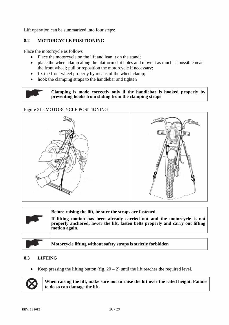
Lift operation can be summarized into four steps: 8.2 MOTORCYCLE POSITIONING Place the motorcycle as follows
• Place the motorcycle on the lift and lean it on the stand; • place the wheel clamp along the platform slot holes and move it as much as possible near
the front wheel; pull or reposition the motorcycle if necessary; • fix the front wheel properly by means of the wheel clamp; • hook the clamping straps to the handlebar and tighten
Clamping is made correctly only if the handlebar is hooked properly by preventing hooks from sliding from the clamping straps
Figure 21 - MOTORCYCLE POSITIONING
Before raising the lift, be sure the straps are fastened. If lifting motion has been already carried out and the motorcycle is not properly anchored, lower the lift, fasten belts properly and carry out lifting motion again.
Motorcycle lifting without safety straps is strictly forbidden
8.3 LIFTING
• Keep pressing the lifting button (fig. 20 – 2) until the lift reaches the required level.
When raising the lift, make sure not to raise the lift over the rated height. Failure to do so can damage the lift.

REV. 01 2012 27 / 29
8.4 STANDING
• When the required position is reached, lower the lift to engage the mechanical safety and let the lift stand.
8.5 LOWERING
• Be sure the safety area is free of people and objects; • Push the lifting button to raise the lift a little bit to clear off the safety; • Turn the safety handle clockwise to release the mechanical safety (ref. fig. 2); • Keep pressing the lowering handle (fig. 20 – 4), the lift will descend under the
motorcycle’s and its own weight; • Lower the lift completely.
REV. 01 2012 28 / 29
CHAPTER 9 – MAINTENANCE
Only trained personnel who knows how the lift works, must be allowed to service the lift.
To service properly the lift, the following has to be carried out: • use only genuine spare parts as well as equipment suitable for the work required; • follow the scheduled maintenance and check periods shown in the manual; • discover the reason for possible failures such as too much noise, overheating, oil blow-by,
etc. • refer to documents supplied by the manufacture or dealer to carry out maintenance.
Before carrying out any maintenance or repair on the lift, disconnect the power supply, padlock the general switch and keep the key in a safe place to prevent unauthorized persons from switching on or operating the lift.
9.1 ORDINARY MAINTENANCE The lift has to be properly cleaned at least once a month using self-cleaning clothes.
The use of water or inflammable liquid is strictly forbidden.
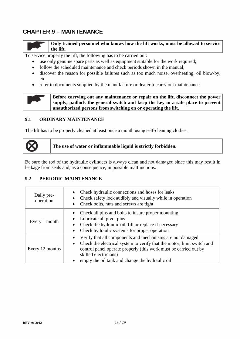
Be sure the rod of the hydraulic cylinders is always clean and not damaged since this may result in leakage from seals and, as a consequence, in possible malfunctions. 9.2 PERIODIC MAINTENANCE
Daily pre-operation
• Check hydraulic connections and hoses for leaks • Check safety lock audibly and visually while in operation • Check bolts, nuts and screws are tight
Every 1 month
• Check all pins and bolts to insure proper mounting • Lubricate all pivot pins • Check the hydraulic oil, fill or replace if necessary • Check hydraulic systems for proper operation
Every 12 months
• Verify that all components and mechanisms are not damaged • Check the electrical system to verify that the motor, limit switch and
control panel operate properly (this work must be carried out by skilled electricians)
• empty the oil tank and change the hydraulic oil

REV. 01 2012 29 / 29
CHAPTER 10 – TROUBLESHOOTING
A list of possible troubles and solutions is given below
TROUBLE: POSSIBLE CAUSE: SOLUTION:
The lift does not work
The power switch is not turned on Turn the switch on
There is no power Check Power on to restore if necessary
The electrical wires are disconnected Reconnect
Fuses are blown Check for correct voltage Replace
The lift does not raise
The lift is overloaded Check the vehicle weight The motor direction of rotation is not correct.
Interchange the two phases on the main switch
The oil in the power unit is not sufficient. Add some hydraulic oil
The UP button is faulty. Check UP button and connection for proper operation. Replace if needed
The maximum pressure valve clogged or leaks
Check and clean if dirty, or replace if faulty
The lowering valve does not close. Check and clean if dirty or replace if faulty
The suction tube or pump filter is dirty. Check and clean if needed.
Presence of air in the hydraulic system Bleed the hydraulic system
The lifting capacity is not sufficient
The pump is faulty Check the pump and replace if needed.
Oil leakages in hydraulic circuit Check the circuit for any leakage
The lift does not lower when the lowering handle is pressed
The lowering valve does not work properly
Check the valve and replace if needed.
The safety lock is not released Release the safety lock.
The lift does not lower smoothly
Presence of air in the hydraulic system Bleed the hydraulic system
Lubrication of sliders is not enough. Grease
Sliders are damaged Replace The motor does not stop when the lift reaches it
maximum height
The maximum height limit switch does not work
Check the limit switch and replace if needed


CORMACH S.r.l. via A. Pignedoli, 2 42015 CORREGGIO (RE) ITALY Tel. +39 0522 631274 - Fax +39 0522 631284 e-mail: [email protected] www.cormachsrl.com