l e v e l d i v i s i o n transparent level gauges gauge... · general instruments consortium...
TRANSCRIPT

Features
Concept and Principle of operation Sealing Gaskets, Cushions and Glasses
L E V E L D I V I S I O N
TDSTLG2010
n Transparent level guage applicable upto 200 kg and upto 400 deg cent
n Cryo applications upto-196 deg centn Toughened glass and borosilicate glassn For applicability in critical, acidic, cryo and high temperature zone n IBR certified device availablen NACE, H2S service compatibility applicable n Non frost extension and high temperature extension
www.general-gauges.com Technical InformationTransparent Level Gauges
Liquid Level Gauge provides direct observation of liquid level in a tank/vessel, rising and falling level of the liquid inside the tank/vessel can be observed through the glass assembled in the gauge. The liquid level is discriminated in the form of different transparency of the two media. The gauge is mainly recommended for color liquids, steam water and interface liquid level.
Transparent Liquid Level Gauges, designed and built for a wide range of high temperature and high pressure applications. Our transparent level gauge is used to make, besides other applications include observation of the level of corrosion-proof and chromatic liquids.
The most advantage of this type is for easy level reading of boiling liquids. When liquids are boiling, their bubbles make the surface level indistinct. The manual adjustment of isolation valve at the input of the media entering the chamber reduces the bubbling. Therefore the level gauge ease to read the level or bubbling liquids. It also provides advantages for highly dense and viscous liquids, as the body is made of forged construction only.
This level gauge is designed and manufactured for easy and accurate reading the liquid level of highly foamy liquids. The gauge has a relatively spacious internal area where foamy liquid is held from forming foams.
Sealing gaskets and cushions for tight sealing at rated pressure and temperature.Tight sealing PTFE with glass inserted, GFT and SS316 impregnated in graphite are the special features of the gaskets General Instruments Consortium provides.
n Heat tracing available n Level 1 radiographed body available n Helium leak test proved design @ 10(-7) mbarlt/secn Viscous media (max upto 380 cst and upto 100 deg cent)
besides other acidic, non acidic, steam water median CE applicability n Applicable for refinery, petrochemical, chemical, power,
radioactive, fertilizer, food, pharma, metal industry applications
Transparent Level Gauges
8

Special Application
Special Application
Special Application Special Application
L E V E L D I V I S I O N
TDSTLG2010
www.general-gauges.com Technical InformationTransparent Level Gauges
If a conventional level gauge is used for extreme low temperature applications, it becomes difficult to observe the level of liquid as the gauge front tends to freeze. To get rid of this problem, an acrylic non-frosting plate is mounted in front of the gauge. So the observation of the liquid level is much easier this way.
Our Non-Frosting Transparent Level Gauges are classified depending on the process temperature, the height of the non-frosting plate window may be selected from 80 to 250 mm.
Transparent
For a jacket type requirement application. This gauge is used to read the level of high congealable or ebullient liquids. The principle is to inflow a steam for congealable liquids and a cold water for enbullient liquids through the inside of the jacket to ensure accurate and reliable level observation.
This type is used for observing the fluid by changing it into state of liquid after heating or cooling it through jacket according to fluid's features. Our standard is that the inlet of the jacket for steam or cold water is ½” NPT(M) and or 15 NB flange. Others are available on request.
More severe demands may often be required on liquid level gauges in terms of resistance to corrosion, and this is accomplished by lining or coating all wetted parts. The most important aspect of this process is the preparation of the metal substrate.
Transparent level gauges with illuminator are useful for observing the fluid level in a dim place or at night by using an explosion-proof and weather-proof. The illuminator can be mounted on all types of transparent level gauges.
Transparent Level Gauges
9

L E V E L D I V I S I O N
10
High tensile nuts and bolts to handle high pressure upto 200kg working pressure and high temperature upto 320 deg cent application
Needle, ball and globe valves upto 1500# at various applicable material suitable to pressure and temperature and media all in forged construction and IBR approved
transparent level gauge at 150# rating at 125 deg cent and FF end connection with auto ball check valve and vent and drain valves in Polypropylene material
Type TransparentLiquid Chamber In forged construction: Carbon steel, SS 304, SS304L, SS316, SS316L, Monel,
Titanium, Inconnel 600, Hastealloy C, PolyPropylene, others on request, subject to Pressure and temperature condition
Cover plate In forged construction: Carbon steel, SS 304, SS304L, SS316, SS316L, Monel, Titanium, Inconnel 600, Hastealloy C, PolyPropylene
Cushion CAF, PTFE, Grafoil, Graphite Gasket CAF, PTFE, Grafoil, Graphite Fastners SS, ASTM A 193 Gr B7/A194Gr 2 H Scale Alluminium anticorossion powder coated and SS engraved in mm Glass Klinger/Illmadur applicable till 320 deg cent as per DIN 7080/7081, BS 3463,
JIS B 8211, Toughened Borosilicate glassProtection shield for temperature upto 550 deg cent Mica shield of 0.2/0.35/0.5mm
Technical Specifications: Table-1 Material of Construction
www.general-gauges.com Technical InformationTransparent Level Gauges
Transparent Level GaugesTDSTLG2010

L E V E L D I V I S I O N Transparent Level Gauges
11www.general-gauges.com Technical InformationTransparent Level Gauges
Borosilicate glass Upto 400 deg cent and higher applicability on special protectionToughened glass Upto 150 deg centGlass thickness 17 mmGlass width 30 mmGlass dimensions type 250 mm and 340 mm Operating pressure applicable as input 100 kg, higher depending on temp Shell test applicable, pressure 200 kg at 20 deg centShell test applicable, temperature Max 400 deg cent depending on selected MOC Cryo applicability applicable (non frost at the glass) Max upto 200 kg and upto -196 deg centCushion and gasket thickness 1.5 mm applicable for -194 deg cent to upto 400 deg cent against suitable MOC Centre to centre distance Max upto 3000 mm applicable with desired accuracy and visibilityVent /drain ½” plugged / ½” needle valve / ½” ball valve /1/2” globe valve Process connection 15 to 50 mm flanged / upto 25mm screwed / socket weld and others on request
Technical Specifications: Table-2 Technical data
Temperature °C 0…-20 -21…-45 -46…-100 -101…-160 -161…-200 Recommended Materials LTCS LTCS 304SS 316SS 316LSS Acrylic Height mm 80 100 150 200 250
Technical Specifications: Table-3 Temp rating and dimensions of non-frosting plates
1 230 1 0 1
2 320 0 1 1
3 495 2 0 1
4 585 1 1 1
5 675 0 2 1
6 760 3 0 2
7 850 2 1 2
8 940 1 2 2
9 1030 0 3 2
10 1115 3 1 2
11 1205 2 2 2
12 1295 1 3 2
13 1385 0 4 2
14 1470 3 2 3
15 1560 2 3 3
16 1650 1 4 3
17 1740 0 5 3
18 1825 3 3 3
19 1915 2 4 3
20 2005 1 5 3
21 2095 0 6 3
22 2180 3 4 4
23 2270 2 5 4
24 2355 5 3 4
25 2445 4 4 4
26 2535 3 5 4
27 2625 2 6 4
28 2715 1 7 4
29 2805 0 8 4
30 2890 3 6 5
31 2980 2 7 5
Technical Specifications: Table-4 Visible Length According to Sections
Sr. No. Visible Length (of level gauge) in mm (glass length = 250 mm) (glass length = 340 mm) (on special request) if applicable
No. of Sections VI No. of Sections IX No of Illuminator
TDSTLG2010

L E V E L D I V I S I O N Transparent Level Gauges
12
TDSTLG2010
www.general-gauges.com Technical InformationTransparent Level Gauges
Rating Upto 15 W / 25W GLS Lamp or 15W LED Lamp with or without Flashing 240 VAC Construction In cast alloy LM6Gas Group IIA, IIB , IIC as per IS 2148 / 2004Deg of protection IP66 as per IS : 12063 /1987CCE Certificate A/P/HQ/MH/104/1817Earthing 2Nos. External & 1 No. InternalEnclosure Anticorrosion Powder Coated Light Grey / Blue shade 631 of IS:5Cable Entry 2 Nos. ¾” ET With cable glands Mounting Transparent acrylic sheet with mounting bracket
Technical Specifications: Table-5 Illuminator Specifications
Technical Specifications: Table-6 Indicative weights in kgs
320 17 25 45 1 0.5 5 2585 30 45 80 2 1 5 2
1030 60 90 162 3 1.5 10 21915 110 165 On request 5 2.5 15 22980 160 On request On request 9 4.5 25 2
Transparent With isolation With isolation With isolation Add on Add on Add on Add onlevel guage valve (upto 1” RF valve (upto 1” RF valve (upto 1” for for for for ball
visible length flange) and with flange) and with input) and with heating frost illuminator valve in mm handle with drain handle with drain handle with drain jacket extension applicable replacing
and vent plug and vent plug and vent plug for the the drain(upto 300# body) (600# body) (900# & 1500# body) visible length & vent plug
Construction and dimensional cross sectional overview
The gauge consists of a body having machined to have a liquid Where high temperature and corrosions are liable to occur, it can be furnished with a mica shield to prevent it from being corroded. There types are preferably used for reservoir tanks that require a relatively long visible length by constructing the supporter.
The transparent level gauge is assembled firmly with gasket, transparent glass, cushion gasket and gauge cover on the body by stud-bolts. The most advantage of this type is that it has no invisible sections (dead band). Our standard overlapped section is 10 mm as minimum and the gauge is so designed that supporting brackets can be equipped to protect a long multiple connected gauge from distortion of fall down. The scale plate to mount alongside the gauge
Construction (sectional View)
Transparent
Orientation of Process Connection
Top/BottomSide/Side (Back)Side/Side (Right)Side/Side (Left)
may be available on request by customers to observe the liquid level more accurately.
The gauge is used with a special reflex type gauge glass which has wider V-shaped refractive grove and red coating on the outside of the glass. It provides a clear observation of liquid level because of made refracting red colour on th V-groove for steam or beyond portion of the level and it's colour of fluid itself for liquid portions.
Process Orientation

Process Orientation
Isolation Valve
L E V E L D I V I S I O N
13
TDSTLG2010
www.general-gauges.com Technical InformationTransparent Level Gauges
Transparent Gauges manufactured by GIC will provide at ease the orientation as per your convenience to have the maximum visibility with respect to process changes i.e. level, isolation valve settings, whether any kind of leakages, leakages through plugs for vent and drain, settings for needle/ball valves.
All orientations at your process suitability with optimum results
Transparent Level Gauges
1 PROCESS FLANGE 2 NECK 3 BALL 4 ORIFICE 5 NEEDLE 6 BALL STOPPER 7 CAPSULE
Isolation Valve
Bolted Bonnet Screwed Bonnet
Bolted and screwed bonnet offset construction to attain device durability, high stability, low hysteresis, high leakage class, bolted bonnet construction for high temperature and pressure, all construction in forged only with the best level 1 radiographed and attain high leakage class of 10(-5) mbar lt/sec.
Screwed connection for low temperature and pressure with full forged construction and with best of level 1 radiography and attain high leakage sealing class of 10(-4) mbar lt/sec.
Ordering information
We require for a complete level solution the following data:
n The pressuren The temperaturen The densityn The viscosity
1 Liquid Chamber 2 Cover Plate 3 Isolation Valve 4 Inlet Process
Flange 5 Outlet Process
Flange 6 Tail Piece 7 Vent Plug 8 Drain Valve 9 Nipple10 Fastener11 Transparent
Glass12 Gasket13 Cushion
Basic GA drawing indicating the top bottom design with CCD interface with visible length. The distance between cover plate and bolted bonnet offset construction is 70mm and that of screwed bonnet is 80 mm. The glass edge is approx 8mm more in each case against the isolation valve in top bottom design.
n The level that you need to measuren The media namen The media colour in normal eye
Rest leave it us for an engineering sizing and selection to provide a optimum level gauge.
Principle of transparent level glass
Liquid
Transparent glass
Auto Ball check arrangement for suitability on level optimization/leakage
Transparent
L E V E L D I V I S I O N Transparent Level Gauges
14
TDSTLG2010
www.general-gauges.com Technical InformationTransparent Level Gauges
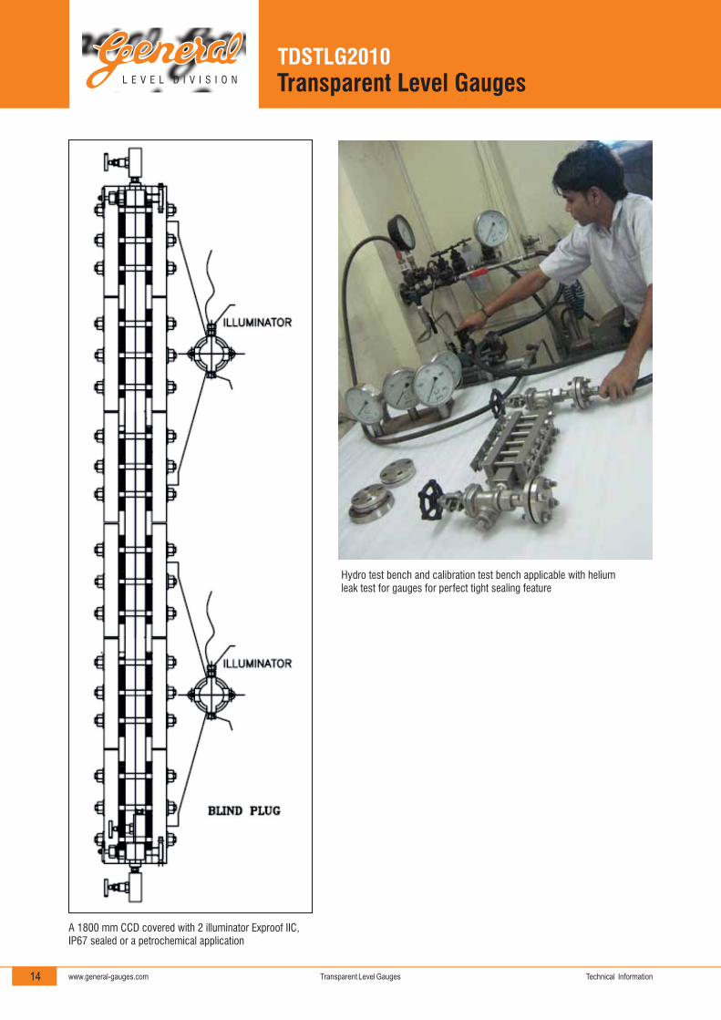
Hydro test bench and calibration test bench applicable with helium leak test for gauges for perfect tight sealing feature
A 1800 mm CCD covered with 2 illuminator Exproof IIC, IP67 sealed or a petrochemical application

L E V E L D I V I S I O N
15
TDSTLG2010
www.general-gauges.com Technical InformationTransparent Level Gauges
Transparent Level Gauges
TLG-TBV-1000-25F150-CCC-LCC-SPP-AL-NA-Z
MS
Special Features
Non – Frost Extension
Mica Shield (For TLG only)
NF
IW5
IFA
IFC
IC
NA
IW7
Heating Jacket
Illuminator-Weatherproof IP - 65
Illuminator-Weatherproof IP - 67
Illuminator-Flameproof Gr. IIA/IIB
Illuminator-Flameproof Gr. IIC
IBR Certification
Not Applicable
HJ
Calibrated Scale
AluminiumAL
SSSS
Drain
½” NPT F, ¾” NPT FP
½” Needle ValveN
½” Ball ValveB
Vent
½” NPT F, ¾” NPT FP
½” Needle ValveN
½” Ball ValveB
Isolation Valves
Screwed Bonnet Offset ConstructionS
Bolted Bonnet Offset ConstructionB
Without Isolation ValvesN
Gasket
C.A.F.C
P.T.F.E.P
GraphoilG
Cushion
C.A.F.C
P.T.F.E.P
GraphoilG
Toughened Borosilicate Glass
Klinger / Illmadur make or equivalent
IndigenousL
F
Fasteners
SS
ASTM A 193 Gr. B7 / ASTM A 194 Gr. 2HC
S
MOC of Cover Plate
SS 304
CS
SS 304L
SS 316
SS 316L
S4
C
S4L
S6
S6L
Polypropylene
Monel
Titanium
Inconel 600
Hastelloy ‘C’
PP
M
T
I
H
MOC of Liquid Chamber
SS 304
CS
SS 304L
SS 316
SS 316L
S4
C
S4L
S6
S6L
Polypropylene
Monel
Titanium
Inconel 600
Hastelloy ‘C’
PP
M
T
I
H
Flanged Connection
Process Connection
Code
15
20
25
40
50
Size
½”
¾”
1”
1½
2”
Size
150#RF
300#RF
600#RF
900#RF
1500#RF
Code
F
Code
150
300
600
900
1500
Screwed Connection
Code
½”
¾”
1”
1½”
Size
½”
¾”
1”
1½”
Threading Type
NPTM
BSPM
NPTF
BSPF
Code
S
Centre to Centre Distance
Indicate the required Centre to Centre Distance in mm.
1000
Orientation of Process Connection
TBV
SSR
SSL
Top - Bottom Vertical (Partial Visibility)
Side - Side Right (Full Visibility)
Side - Side Left (Full Visibility)
Type of Level Gauge
Transparent Level GaugeTLG
Z
Ordering Information