l m - nasa · · 2013-08-30trade names or manufacturers' names are used in this report for...
TRANSCRIPT

_rH
'1
I''_ °
L_m
0 _1,-,,_.
©
ii
https://ntrs.nasa.gov/search.jsp?R=19900018747 2018-06-18T19:28:53+00:00Z

__ T
r. --v--_k
7_
<i
-£
r
r
L
_ £---- _.T£= _

NASAReferencePublication1240
1990
N/kSANational Aeronautics andSpace Administration
Office of Management
Scientific and TechnicalInformation Division
Liquid Lubrication"Spacein
Erwin V. Zaretsky
Lewis Research Center
Cleveland, Ohio

Trade names or manufacturers' names are used in this report for identification
only. This usage does not constitute an official endorsement, either expressed orimplied, by the National Aeronautics and Space Administration.

Summary
The requirement for long-term, reliable operation of aero-
space mechanisms has, with a few exceptions, pushed the stateof the art in tribology. Space mission life requirements in the
early 1960's were generally 6 months to a year. The proposed
U.S. space station scheduled to be launched in the 1990's mustbe continuously usable for 10 to 20 years. Liquid lubrication
systems are generally used for mission life requirements longerthan a year. Although most spacecraft or satellites have reached
their required lifetimes without a lubrication-related failure,
the application of liquid lubricants in the space environment
presents unique challenges. This report reviews the state ofthe art of liquid lubrication in space as well as the problems
and their solutions.
Introduction
Tribology problems have grown with aerospace advances
made over the past 30 years as shown in figure 1 (from Kannel
and Dufrane, 1986). In the beginning of the space age life
requirements were minutes or hours. In the early 1960's they
were generally 6 months to a year. Early deep-space probeswere notable exceptions, but these probes had relatively few
mechanical assemblies with high cyclic requirements. By the
mid-1960's mission life requirements had increased to 3 to
5 years. By the mid-1970's life requirements of 7 to 10 yearswere common (Ahlborn et al., 1975). The proposed U.S. spacestation scheduled to be launched in the 1990's must be
continuously usable for 10 to 20 years; that is, a 10-year design
life requirement with a 20-year life goal (Dolan and
McMurtrey, 1985). Despite significant advances in lubrication
and mechanical component technology, the demands of these
aerospace systems appear to grow faster than the technology.Lubrication problems in space include
(1) Very low ambient pressure(2) Presence of atomic species other than the normally
encountered molecular species
(3) Thermal radiation(4) Absence of a gravitational field
The absolute pressure outside the Earth's atmosphere (e.g.,above 1609 km (1000 miles) altitude) is approximately 10 - 13
torr; the absolute pressure in interstellar space is approximatelyl0-16 torr. Figure 2 shows pressure as a function of altitude
(Jastrow, 1960). The low-pressure environment contributes to
rapid evaporation of the liquid or semisolid grease lubricants
normally employed. Since lubrication ordinarily takes place
by means of a film entrained between sliding or rolling sur-faces, the loss of this film due to evaporation and mechanical
working can result in failure of the mechanism.
With many metals the lubrication function is strongly
influenced by the presence or absence of oxide films on thesemetals. The surface oxides frequently act as protective films
and, in some cases, contribute to the final surface films througheither chemical reaction or chemisorption. At altitudes greater
than 89 km (55 miles) oxygen and nitrogen do not exist as
the ordinary molecular species but rather in the atomic or ionicstate. The reaction rates between most metals and atomic
oxygen are markedly different from those with molecular
oxygen. At altitudes greater than 1287 km (800 miles) atomic
hydrogen and helium are the principal species present.Mechanisms in a closely sealed satellite are likely to operate
in a water vapor pressure of greater than 10 7 torr during
their first year in orbit. The atmosphere may include trace
quantities of carbon monoxide, heavy hydrocarbons, and lightsilicone polymers with an occasional burst of ammonia from
the decomposition products of the hydrazine motors. Some
components on the exterior of the satellite operate in a muchcleaner environment, the gas pressure generally being less than
10- l0 torr, but with occasional bursts of ammonia (Robbins,
1975). Because of the scarcity of oxygen, oxide films are
formed at a rate inadequate for lubrication.
At extremely low pressure levels (where gas conduction andconvection are absent) the temperature levels will normally
be dictated by thermal radiation. Heat will be absorbed byradiation from any object that the mechanism "sees," and the
mechanism will, in turn, reject heat to outer space by radiation.
Various mechanisms will have different temperature levels
depending upon their relative rates of heat gain and loss.Robbins (1975) reports that the temperature is controlled by
using carefully selected thermal blankets to balance the heatabsorbed from the 6000 K (10 341 °F) radiation of the Sun,
the heat radiated by the satellite at 300 K (81 °F), and the
internal heat generation. He states that in order to provide an
equable temperature for electronic components most satellitemechanisms are designed to operate within a narrow
temperature band, usually in the range 280 to 320 K (45 to117 OF). Lubricant evaporation from surfaces is a function
of temperature. Hence, a mechanism's temperature is
important to the lubrication process and thus to its survivability.

_ro
I.-
1950
Strategic _ .Defense / :_pacec_an
Ini_"" Complexity
sta,c_ Tdbology/ problems
Voyage,,/ / I"Shuttle "_ /
/ /"" lubrication (life) .... - Trlbology
/ _t*_LubricalJon ..-." ....... "" solutions
/ / dls_bu¢lon .... ---" "". . / /C oe .....-.--""
--- I I I I I1960 1970 1980 1990 2000 2010
Year
Figure l.--Growth of tribology requirements with advances in space. Kannel and Dufrane (1986).
10, _
1°°
r
- I0 4o0 800 1200 1600 20O0 2400
Al_tude, krn
I I I I0 400 80O 1200
Altitude, mile,=
Figure 2.--Pressure as a function of altitude. Jastrow (1960).
I1600
I28OO
Perhaps the only advantage of operation in space is the
influence of microgravity. Eliminating the weight of a system
from its bearing supports minimizes component wear and
reduces the probability of rolling-element fatigue. However,the bearings are preloaded to give precise location and to avoid
ball skidding (Robbins, 1975). The resultant bearing load is
usually 1 percent or less of its dynamic load capacity. (Thedynamic load capacity is defined as a theoretical load that,when applied to the bearing, will result in a life of 1 million
inner-race revolutions.)
Spacecraft and satellites are lubricated with dry films,liquids, metallic coatings, greases, or combinations of these
lubricants. Liquid lubrication systems are generally used formission life requirements of over a year, (Ahlborn et al.,
1975). The application of liquid lubricants in the space
environment presents unique challenges. This report reviewsthe state of the art of liquid lubrication in space as well asthe problems and their solutions.
Lubricant Type and Selection
Corridan (1959), Freundlich and Hannan (1961), and Clauss
(1961) conducted early ball bearing tests in vacuum. They usedAISI 440C stainless steel instrument bearings with bore
sizes from 3.18 to 9.53 mm (1/8 to 3/8 in.) and with oil-
impregnated, machined phenolic composition retainers. Theyobtained good performance with a silicone oil (General Electric
Versilube F-50) (Bisson 1964). The operating times of these
bearings were 1000 to 4600 hr, considered adequate for the
early 1960's. Today they would not be acceptable. Young and
Clauss (1966) tested both AIS152100 and AIS1440C bearings
with phenolic cages lubricated with chlorophenyl methylpolysiloxane oil at 10 -7 to 10 -9 torr and 422 K (300 *F).The bearings failed in less than 15 000 hr. Silicone-base fluids
are not considered to give good lubrication for long-term
operation because of their poor boundary lubricating propertiesand their tendency to creep (Roberts et al., 1990).
Young and Clauss (1966) conducted additional tests with
dibasic-acid-ester-base lubricants: MIL-L-6085 (diester-base
oil with corrosion inhibitor) and a dioctyl sebacate. Both
lubricants resulted in failures in less than 3600 hr. Failure in
these bearings and in the silicone-lubricated bearings wereassociated with either thickening or loss of lubricant. These
tests suggest that the ester-base lubricants are less satisfactorythan the silicone-base fluids in vacuum even though the esters
are superior lubricants for rolling-element bearings in air.

YoungandClauss(1966)alsoperformedtestswithnaphthenicandparaffinicmineraloils.Thenaphthenic-oil-lubricatedbearingsfailedin743hrbecauseofacompletelossofoil.Theparaffinic-oil-lubricatedbearingslastedmorethan12000hr withoutfailure.Thesetestssuggestthatin themid-1960'stheparaffinic-baseoil hadthebestpotentialforlong-lifeapplicationsinspace.
Inthe1970'stwolubricantsweredevelopedandsuccessfullygroundtestedintheUnitedKingdom:asuperrefinedmineraloil(BP110)andatriesterfluid(BP135)(Robertsetal.,1990).Theproblemsassociatedwith highvaporpressureandhighoutgassingwereavoidedby usingmolecularseals,antimigrationbarriers,andoil reservoirs(Parker,1987).Hence,thekeytolong-lifereliableapplicationistomaintaina lubricantpresencein thebearingcavity.
Superrefinedmineraloilsbecamethelubricantsof choiceforsuchdevicesasmomentumwheels,reactionwheels,anddespinmechanisms.Themostpopularsuperrefinedmineraloil lubricantsareKG80(Kendal)andApiezonC (Shell).Interestin fluidsof variousviscositiesalsopromptedthedevelopmentofsuperrefinedgyroscope(SRG)lubricants.TheseSR6fluidsrepresentahomologousgroupthatallowstheusertoselectafluidhavingspecificviscositycharacteristicsfora givenapplication(KannelandDufrane,1986).Typicalviscosity-temperaturecharacteristicsof theselubricantsaregiveninfigure3.KannelandDufrane(1986)conductedtorquetestsonanR-6instrumentbearingwiththeseSRGlubricants.Theresultsof thesetests(fig. 4) clearlyshowthetorquepenaltyassociatedwithincreasingtheviscosityofthebearinglubricant.However,therearetimeswhenthepenaltyofhighertorquemustbeoffsetbythebeating'sabilitytodevelopagood
10 -3
10"-4
_EE 10 -5
_SRG
number
160
100
KG 8O
6O
4O
3O
20
10
I I 11E-O
10 -6
0 50 100
Temperature, °C
Figure 3.--Viscosity as a function of temperature for a homologous series
of superrefined mineral oils. Kannel and Dufrane (1986).
2.0x10³
1.5Z
1.0
tn .5
t0 30 60 90 120 150 180X106
Kinematic visCOSity at 38 "C, m2/sec
Figure 4--Measured bearing torque as a function of lubricant viscosity for
various lubricants at 25 °C for an R-6 bearing at 480 rpm. Kannc] and
Dufrane (1986).
elastohydrodynamic (EHD) film thickness between the balls and
the races.
Perfluorinated Polyalkylethers
Roberts et al. (1990) report that in more exposed applica-
tions, or where operation at temperatures as low as 200 K
(-100 °F) is required, or where a high viscosity index is
deemed important, the perfluorinated polyalkylethers (PVPE)
are widely used. Because minimal attenuation of infraredradiation occurs with these fluids, they have been used as
lubricants within infrared scanners on spacecraft.
Table I (from Kannel and Dufrane, 1986) presents measured
evaporation rate data for superrefined mineral oil and PFPElubricants. PFPE lubricants have the lower evaporation rates.
In general, evaporation rates tbr a given type of fluid decreaseas the viscosity is increased. For longer life applications thelower loss rates associated with higher viscosities are desirable.
However, the high-viscosity lubricants have the disadvantage
of higher operating torques.The general conclusion has been that the PFPE lubricants are
the most desirable for spacecraft applications. Three com-
mercial PFPE lubricants have been widely used: Krytox PR
143AC (DuPont), Fomblin Z25 (Montecatini Edison), and
Brayco 815Z (Bray). These fluids generally have the lowcst
TABLE I.--EFFECT OF VISCOSITY ON EVAPORATION RATE OF TWO
LUBRICANTS IN A 0.133-MPa (10-6-torr) VACUUM
[Kannel and Dufrane (1986).]
Fluid
Superrefined paraffinic mineral oil (SRG 30)
Superrefined paraffinic mineral oil (SRG 40)
Perfluoro ether a
Perfluoro ether _
Perfluoro ether _
Published
viscosity
at 40 *C,
m2/sec
14 × 106
27
8
28
357
Evaporation
rate at 40 °C,
mg/cm2-hr
18
13
2.2
,19
.0002
aT_pe and manufacturer not specified tn reference

vapor pressure and highest viscosity index of lubricantsconsidered for space application. Fomblin, which contains an
acetal linkage, has a lower vapor pressure and a higherviscosity index than Krytox. However, as more long-term
experience has been gained with these lubricants, degradationof the lubricant has been observed. This degradation hasresulted in high bearing torque noise and excessive wear(Stevens, 1983).
The work of Baxter and Hall (1985) with Fomblin Z25
suggests that the degradation is caused by the presence ofchemically active surfaces, wear particles combined with
exposed radicals in the fluid, or both. Zehe and Faut (1989)and Carre (1987) suggest that metal oxide surfaces in contact
with acetal-containing PFPE lubricants (i.e., Fomblin Z25) will
inevitably result in acidic breakdown of the ethers. Theyconclude that little can be done to the PFPE chains to block
the acidic attack without compromising the viscosity-temperature qualities of the acetal groups.
Mori and Morales (1989a,b) studied the effects of Krytox16256 and Demnum $200 (Daikin) in addition to Fomblin Z25.
Fomblin Z25, a copolymer of perfluoromethylene andperfluoroethylene oxides, is the only one of three fluids
that contains an acetal linkage. Krytox 16256 is a
poly(perfluoropropylene oxide) with pendent -CF 3 groups.
Demnum $200 is a poly(perfluoropropylene oxide). Theproperties of PFPE fluids are sununarized in table II.
Mori and Morales (1989a) found that PFPE decomposition
and the resulting reaction products are dependent on theparticular molecular structure of the PFPE fluid when irradiated
by x-rays under ultra-high-vacuum conditions. They alsostudied the reaction of the PEPE fluids with AISI 440C stainless
steel during sliding under 10 -m torr at room temperature(Mori and Morales, 1989b). All three fluids reacted with the
AISI 440C material during sliding. Fomblin Z25 decomposed
during sliding and gaseous products, mainly COFe, were
TABLE II.--PROPERTIES OF PFPE FLUIDS
[Mori and Morales (1989a).]
Property Fluid
Average molecular weight
Kinetic viscosity at 20 °C, cS
Viscosity index
Pour point, °C
Density at 20 °C, g/ml
Surface tension at 20 °C, dyne/cm
Vapor pressure, torr:
At 20 °C
At 100 °C
tDemnum
$200
840C
500 + 25
210
-53
l. 894
19
5×10 tt
1 × 10 -7
v lomblin I Krvtox
z25 ] z&5695{)01 11 OR)O
255] 2717
355 i .......
661 - 151.85t 1.92:
251 19 i
2.9x10 t:[ 3x10 t._[xlO-g IxlO-_
formed. There were no gaseous products from the Krytox orDemnum fluids.
Solutions to the problem of thermo-oxidative breakdown
should focus on the surfaces in contact with the liquid. Somesuccess in blocking thermo-oxidative degradation of linear
PEPE'S below 570 K (566 °F) has been achieved with the use
of additives containing nitrogen or phosphorous atoms. The
action of these additives may depend upon their ability to blockacidic sites on the surface (Jones et al., 1983, 1985). Other
approaches may involve surface modification to limit
decomposition, since it is the catalytic action of the resulting
surface that accelerates the breakdown (Zehe and Faut, 1989).Table III (from Roberts et al., 1990) lists factors that both
promote and retard PFPE degradation.
Performance Characteristics
Thomas (1980), in order to provide data for ball bearing
torque calculations, performed sliding tests in air using AISI52100 balls with the more common spacecraft lubricants
TABLE III.--FACTORS INFLUENCING PFPE DEGRADATION
[Roberts et al. (1990).]
Factors promoting degradation Faclors retarding degradation
Starved conditions
(e.g.. grease plating)
Low specific fihn thickness (k < 1)
Fomblin Z type of perfluorinated oil
base (linear structure)
Aluminum/titanium substrates at any'
ambient temperature
AISI 52100 bearing steel
High ambient temperature (> 360 °C)
!Sliding surlaces
Vacuum environment
Fully llooded conditions
High specific film thickness {_x > 4)
Fomblin Y type of perfluorinated oil
base (branched structure); Krytox
rarely used in Europe
Hydrocarbon contamination
AISI 440C bearing steel; ceramic
coatings give further improvement
(e.g., TiC -coated balls)
Low ambient [emperature
Surfaces where rolling motion takes
place
Normal atmospheric conditions

Lubricant
ApiezonC
BP 135 a
BP 1 l(I a
KG 80
Fomblin Z25
TABLE IV.--COMMONLY USED LIQUID LUBRICANTS FOR
SPACE TRIBOLOG1CAL APPLICATIONS
Manufacturer
Shell
British
Petroleum
3ritish
Petroleum
Viscosity
at 20°C,
cS
250
7O
520
520
[Thomas (1980). ]
Kendall
Refining
Company
Montecatini
Edison
Vapor
pressure
at 20°C,
torr
4.0× 10 u
7.9×10 '#
3.7xl0 _
<10 _
240 <5.0x 10 ,2
ainu bnger illarkelCd b,*ralor_ tcslcd hut nc_cr I]ov, n ua spaccclall
Description and comments
Vlineral oil with no additives: used as
a reference oil
Synthetic: triester base; boundarylubricant and antioxidant additives
Mineral oil base; high viscosity;
refined to give low vapor pressure;
boundary lubricant additives .
Petroleum base with boundary lubricant
additive tricresylphosphate: also
contains an antioxidant additive
Synthetic fluorinated oil: high density,
low surface tension; high temperature
and high viscosity index; no boundar'
lubricant additives; high thermal
resistance
TABLE V.--COEFFICIENT OF FRICTION AND WEAR
RATE OF STEEL ON STEEL 1N LIQUID-
LUBRICATED SLIDING CONTACT
lThomas ( 1980).]
l_ubricant
Unlubricated, "failed"
after 100 re,,olutions
Apiezon C
BP 135
BP 110
KG 80
Fomblin Z25
Coulomb
friction
coefficient
a0.46
,20+_ .03
.12 +- .015
.13+.015
.13+.02
.12+-.02
Specific
wear rate after
1000 revolutions,
in'/N-n1
19.1_+0.9× 10¹⁵
.93 ± .05
1.04 +- .05
.41 +_.02
.69 +_.03
.49 + .03
aFriclmn io_c rapidl) I_ Ihi_ _aluc
described in table IV. The results of these tests are presented
in table V. At slow speeds, where there is essentially no
elastohydrodynamic lubrication, and with light loads thelubricating properties of the five oils were similar. Apiezon C,which had no additives, exhibited the highest mean friction
coefficient of 0.20. The other four lubricants had lower friction
coefficients, ranging from 0.12 to 0.13. With the exception of
the Apiezon C, which had no boundary lubricant additives,all of the lubricants performed identically in the sliding tests
in air.Stevens (1983), using the same lubricants as Thomas (1980),
performed lubrication tests to determine the wear and torqueof satellite, 20-ram-bore, angular-contact ball bearings
operating at 10 rpm. That speed corresponds to the boundarylubrication regime. The tests were conducted both in vacuumand in air. The results of these tests are shown in figure 5.
_OxlO '4
1
25J
20
_5Z
.9.0
Lubricant Viscosity,cS
O BP 135 70i'-1 Z 25 240
<> APC 250
A BP110 520_7 KG 80 52O
I I I I I I I J
30x10 -4
_s[ Ibl I 1 t I I 1 I I I0 20 40 60 80 1O0 120 140 160 180
Time, hr
(a) Air.
(b) Vacuum (10 _' torr).
Figure 5,--Ball bearing torque as a function of lubricant viscosity. Bearing
bore, 20 ram; contact angle, 15°; cage, one-piece phenolic (outer-race
riding); number of balls, 10: speed, 10 rpm; thrust load, 40 N. S|evens
(1983).
Figure 5 shows the mean torque, or the average of the torquevariations, as a function of time lbr each lubricant. Although
the torque differences between the five lubricants are notconsidered significant, there appears to be a trend of increasing
torque with increasing lubricant viscosity. This trend correlates

withthetrendshowninfigure4byKannelandDufrane(1986).Theseresultsstronglysuggestthatthemagnitudeanddif-ferencesinbearingtorquearedueto viscouseffects.Thevariationintorqueaboutthemeanvaluewasreportedtobesimilarforthefivelubricants.ThehighesttorquewasobtainedwiththeKG80lubricant,whichhasaviscosityof520cSat20 °C.ThelowesttorquewasobtainedwiththeBP135lubricant,whichhasaviscosityof 70cSat 20°C.Onthebasisof workbyToddandStevens(1978)withacagelessthree-ballbearing,Stevens(1983)predictedthatthetorqueduetospin,hysteresis,andmicroslipwouldbe14x 10.4N-re.IntestsbyStevens(1983)withKG80andApiezonCatspeedsof0.2and1rpmandathrustloadof40N,thetorqueofthesebearingsmeasuredat10rpmrangedfrom15× 104to 17x 104N-re.At 10rpmandahigherloadof 400NthetorquewastesswithKG80(120× 10-4N-m)thanwithApiezonC (200 × 10 4 N-m). These results suggest that at
the higher load the torque is dependent on the sliding friction
coefficients reported in table V by Thomas (1980). Hence,
it may be reasonably concluded that at fractional speeds bearing
torque is related to ball spin, hysteresis, and microslip. At lightloads and extremely low speeds the torque is related to
lubricant viscosity, primarily because of cage friction. At lowspeeds and high loads the torque is related to the Coulomb
friction coefficient (table V). In satellite applications the onlyload the bearing experiences in the space environment is the
applied bearing preload, which is generally low. If the speed
is high enough for a sufficient elastohydrodynamic film toform, the bearing torque will be a function of the lubricant's
viscosity at the operating temperature of the bearing.
In the 1960's Young et al. (1963) and Young and Clauss(1966) performed extensive lubricant research in vacuums
ranging from 2 x 10 7 to 4 x 10⁻⁹ torr. The following typesof liquid lubricant were endurance tested with both AISI 52100and AISI 440 ball bearings:
(1) Paraffinic and naphthenic mineral oils
(2) Chlorophenyl methyl polysiloxanc oils
(3) Mixed isomeric five-ring polyphenyl ethers(4) Diphenyl bis-n-dodecyl silane(5) Dibasic-acid-ester-base oils
These lubricants are listed here in the order of the endurance
lives obtained with the bearings. The best results and the
longest lives were obtained with bearings having a paper-basedphenolic cage lubricated with a paraffinic-base mineral oil
containing additives used for gyroscope bearings. The phenolic
cage is used to retain and supply the oil. Linen-based phenolic
cages with the same lubricant did not provide as good results.The linen phenolic cages tended to dry out and crack. Tests
were run with the chlorophenyl methyl polysiloxane "asreceived" and after the 50 percent most volatile fraction was
removed by distillation. These tests were run to determine
whether removing the most volatile material would lengthen
the operating time in vacuum. The as-received material gaveat least twice the life (Young et al., 1963).
Ftom and Haltner (1968) list early satellite applications usingchlorophenyl methyl silicones. The most common of these
fluids was General Electric Versilube F-50. However, the use
of F-50 for space applications appears to have met disfaw)r
in the 1970's. The fluid polymerizes both in vacuum and in
air because of microasperity interaction. Experience with
chlorophenyl methyl silicones has also shown that, where there
are high sliding velocities, large amounts of wear can occur
in angular-contact ball bearings and sliding surfaces. Meeks
et at. (1971) conclude that the estimated life belbre significant
torque fluctuations (greater than two times average) for
F-50-1ubricated, small bearings run at 55 rpm below 10 8
torr is less than l year. This result is due to thermally induced
chemical changes in the oil. Meeks el al. (1971) predict that the
ultimate failure life of these bearings witl be less than 2 years.Fleischauer and Hilton (1990) discuss the use of
polyalphaolefin (PAO) and polyolester (f,f_) oils us possible
substitutes for linear perfluorinated polyalkylethers. Theysuggest that these oils can be synthesized and blended to
produce in a controlled way viscosities, vapor pressures, pourpoints, and other properties that can meet various spacecraftrequirements. These oils can also be blended with standard
additive packages similar to those in conventional mineral oils.
However, there does not appear to be a definitive data base
that would allow using these oils in a satellite or spacecraft
system at this time with a reasonable degree of confidence.
Elastohydrodynamic and BoundaryLubrication Effects
Lubricant Function
The primary function of a liquid lubricant in space appli-cations is to separate surfaces in relative motion so that the
surfaces do not sustain major damage and to keep the
coefficient of friction between the surfaces relatively low. A
number of lubrication regimes, depending on the type ofintervening film and its thickness, can be identified. These
lubrication regimes can be depicted by the Stribeck-Herseycurve shown in figure 6 (from Jones, 1982). This curve takesthe [brm of the friction coefficient as a lunction of the
parameter ZN/P, where Z is the viscosity o1"the liquid, N isthe velocity, and P is the load.
At high values of ZN/P, which occur at high speeds, low
loads, and high viscosities, the surfaces are completelyscparated by a thick (0.25 #m; 10 --s in.) lubricant film. This
is the hydrodynamic lubrication regime, where friction is
determined by the rheology of the lubricant. For nonconformal
concentrated contacts, where loads are high enough to cause
elastic deformation of the surfaces and pressure-viscosityeffects on the lubricant, another fluid film regime, elasto-
hydrodynamic lubrication, can be identified. In this regimefilm thickness may range from 0.025 to 2.5 _m (10 _' to

104in.).Asthefihnbecomesprogressivelythinner,surfaceinteractionsbegin.Thisregimeof increasingfriction,whichcombinesasperityinteractionsandfluidfihneffects,isreferredtoasthe"mixed-lubricationregime."Finally,atlowvaluesoftheZN/Pparameteristheboundarylubricationregime.Thisregimeis highlycomplex,involvingmetallurgy,surfacetopography,physicalandchemicaladsorption,corrosion,catalysis,andreactionkinetics.Itsmostimportantaspectisthelbrmationof aprotectivesurfacefihntominimizewearandsurfacedamage.Theformationof surfacefilmsisgovernedbythechemistryofthefilm-lbrmingagentaswellasbythesurfaceofthesolidandotherenvim.nm,entalfactors.Theefl'ectivenessof surfacefilmsin mmmltzmgwearisdeterminedbytheirphysicalproperties,whichincludeshearstrength,thickness,surfaceadhesion,fihncohesion,meltingpointordecompositiontemperature,andsolubility.
BesidestheStribeck-Herseycurve(fig.6)alreadydescribed,anidealizedplotofwearrateasafunctionof relativeloadcanalsodelineatethevariouslubricationregimesandsomeweartransitions.RegionO-Aoffigure7(fromBeerbower,1972)encompassesthehydrodynamicandelastohydrodynamiclubricationregimes,thelatteraspointAisapproached.Sincenosurfaceinteractionsoccurin thisregionexceptduringstartupandshutdown,littleor nowearoccurs,exceptthatcausedbyrolling-elementfatigue,whichcanoccurwithoutsurfaceinteractions.RegionA-X is themixed-lubricationregime,wheresurfaceinteractionsbeginto occuratA andbecomemoreprevalentaspointX isapproached.Wearislowbecausefluidfihneffectsstillexist.
h ~ 0.025 to 2.5 pm(lO '6 to 10-4in.)
O. 00_5 p.rn(10 -7in.) I
h~ I _.
.150 --_
O
o .3 \ I/
.ool I I II I II I t
ZN = IViscosit_)(Vel°ca_)-p (Load)
Figure 6 --Coefficient of friction as function of viscosity-velocity-load
parameter (Stribcck-Hersey curve). Jones (1982).
_oE
8
•"r t._
IIIIIIIIt
A X B
Rela_ve load
• _ Seizure0
.--Transition
f4 Z'
/ 1
I"II
I
y Z
Figure 7--Wear rate as a function of relative load, depicting various lubrication
regimes. Beerbower (1972).
Region X-Y is the boundary lubrication regime. The degreeof metal-to-metal contact and the wear rate increase as the load
increases. Wear is mild and tends to be corrosive to the left
of B and adhesive to the right of B. The location of B is quite
variable and depends on the corrosivity of the lubricant
formulation. For a noncorrosive lubricant adhesive wear can
occur at X. On the other hand, a corrosive additive can extend
the boundary regime to Z' before boundary film failure
occurs. Region Y-Z is the severe wear regime, where severeadhesion and scoring occur. Mechanisms cannot operate
successfully in this regime, and therefore the location of this
transition point is quite important. At Z total surface failure
occurs, followed by seizure.In the boundary lubrication regime many properties of the
liquid lubricant become important: shear strength, filmthickness, melting point, and chemical reactivity with the
surface. Operating variables that affect lubricant film perform-ance include load, speed, temperature, and atmosphere, as
already discussed. Additives present in the lubricant to serve
specific functions, such as antiwear, antifoam, and antioxidantadditives and viscosity improvers, also affect behavior
(Jones, 1982).
Elastohydrodynamic Theory
Elastohydrodynamic (END) lubrication theory is well
documented by Dowson and Higginson (1966) and Hamrockand Dowson (1981). The Grubin (1949) EnD fihn thickness
formula is as follows:
H = 1.95 G°73U °73W o(_1
where
H
G
film thickness, h/R,
materials parameter, o_E'

Wo_
E'
speed parameter, uqo/E'R _
load parameter, F/E'R_
pressure-viscosity exponent, GPa
reduced modulus of elasticity.
I (psi -I)
1 1 (l-v_ l-v!'_E'-2,, E, /
It
R,
average surface speed, (uj + u2)/2, m/sec (in./sec)
atmospheric viscosity, N-sec/m 2 (lb-sec/in.2)
equivalent radius in rolling direction, m (in.),
1 1 1- +
R, R,. = R,.2
F normal applied load, N (lb)
El,E2 Young's modulus for body 1 and body 2, GPa (psi)
h film thickness, m (in.)
pt,p: Poisson's ratio for body I and body 2
The variations in EHD theory and the resulting formulas are
beyond the scope of this report. Suffice it so say that the
variations between the EHD film thicknesses calculated by thedifferent formulas are less than the variations between the
various sets of experimental data used to verify the theories
(Coy and Zaretsky, 1981). This is illustrated in figure 8, which
shows the film thicknesses calculated by the theories of
Hamrock and Dowson (1977), Grubin (1949), Cheng (1972),and Chiu (1974). A theoretical model for oil starvation in a
rolling-element bearing was formulated by Chiu (1974).
Figure 8 also compares the results from Chiu's (1974) analysiswith his experimental data and experimental data of Coy andZaretsky (1981). Oil starvation in the Hertzian contacts even
under flooded conditions appears to be the primary cause ofthe deviation of the experimental data from classical EHDtheory (Coy and Zaretsky, 1981).
G = 5000
10-3 _" Hamrock and Oowson (1977} -.--,
-- G=_oo
"_ --" Cheng (1972) --_ /.,,_
Orubin (1949)_ /_"'_ ,,.-,.,.__ O 00 oOQ0
--" _1_-_. oO0 0 e_._--Chiu(1974}
=__ 10 -5
.5 __._oO--,n • Chiu (1974)
O Coy and Zaretsky (198t)Ei5
lO-6 I _lJlJltJ I IlJlJhJ I IlflJll[ I illllhJ
10 -8 10-7 10-6 10-5 10-4
Dimensionless Contact lubricant flow number, GU = _Uho/R z
Figure 8. Theoretical effect of kinematic starvation and inlet shear heating
on fihn thickness and comparison with experiment, Coy and Zarctsky ( 1981 ),
The measure of the effectiveness of the lubricant film is the
X ratio (i.e., the central film thickness divided by thc composite
surface roughness of the rolling-element surfaces h,./o).Usually the root mean square (rms) surface finishes of the
contacting bodies o] and 02 arc used to determine thecomposite surface roughness as follows:
o= aT+o
The )x ratio can be used as an indicator of rolling-clement
performance and life. For h < 1, surface smearing or
deformation, accompanied by wear, will occur on the rolling
surface. For 1 < X < 1.5, surface distress may be
accompanied by superficial surface pitting. This type of pittingwas observed by Stevens (1983) in oil-lubricated satellite ball
bearings. For 1.5 < X < 3, some surface glazing can occurwith eventual roller failure caused by classical subsurface-
originated rolling-element fatigue. At X _> 3, minimal wear
can be expected with extremely long life; failure will eventuallybe by classical subsurface-originated rolling-element fatigue.
The most expedient, although not the least expensive, way ofattaining a high X ratio is to select a high-quality surface finish.
The effect of film thickness is to reduce the magnitude andinstability of the torque, as shown in figure 9.
A good example of an effective lubricant film is providedby the NASA Solar Maximum Mission satellite, known as Solar
Max. The 3-ton spacecraft came crashing into the atmosphereon December 2, 1989, after 9 years in orbit. In 1984, Solar
Max became the first satellite to be captured and repaired in
space. It had been in orbit for 4 years when NASAspace shuttle
astronauts replaced its inertial reference unit and returned the
original unit to Earth. The unit had three gyroscopes, each
with two ball bearings. One of these gyroscopes wasdisassembled and its bearings examined. The AISI 440C
bearings had a 7-mm bore. They had run continuously at
6000 rpm. The cages were made from a phenolic material
impregnated with KG 80 lubricant. The two bearings were
found to be well lubricated, with oil still in the cages. Iron
and chromium debris particles were found in both bearings.
The surfaces of the bearing raceways and balls had superficial
pits and scratch-like deformations. The wear debris, which
was considered small, was attributed to the pits. This
micropitting appeared similar to and confirmed that reported
by Stevens (1983). It was concluded that these bearings would
have lasted for their predicted life of 5 years (Uber, 1985),
and this conclusion was borne out by the additional 5-yearoperation of the Solar Max satellite.
Design Criteria
Ahlborn, et al. (1975) report that they designed theirbearings to operate at X < 1 and maximum Hertz stresses less
than 1.03 x 10 9 N/m 2 (150 000 psi). However, their test
data indicate that failure to meet these criteria does not mean
that long life is precluded. They conducted two separate tests
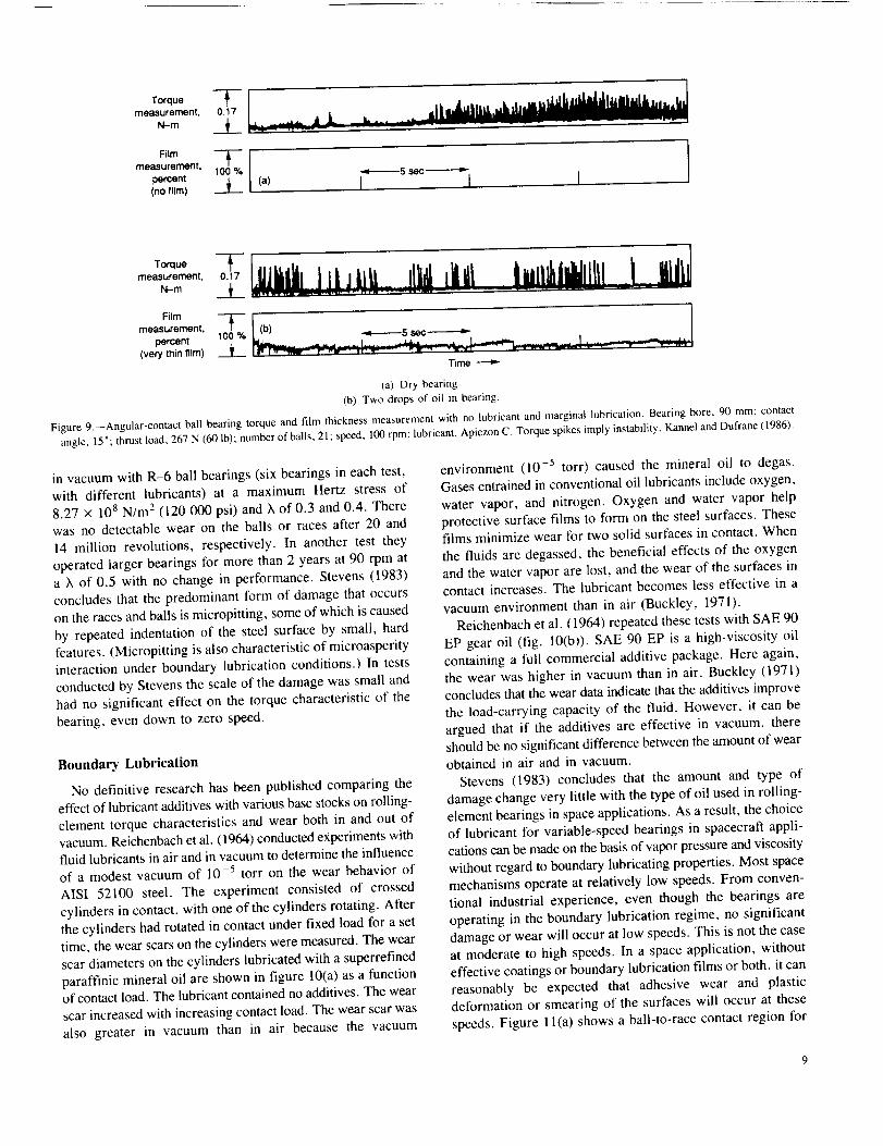
Torque Tmeasurement, 0.17
N-m
measurement. -4-_--5 secpercent(no film) _ (a) I [ I '
To. uemeasurement, 0.17
N-m
measurement,
percent 100 Yo(very thin film) mE
Time
(a) Dry bearing.
(b) Two drops of oil in bearing.
Figure 9.--Angular-contact ball bearing torque and film thickness measurement with no lubricant and marginal lubrication. Bearing bore, 90 mm; contact
angle, 15"; thrust load, 267 N (60 lb); number of balls, 21; speed, 100 rpm; lubricant, Apiezon C. Torque spikes imply instability. Kannel and Dufrane (1986).
in vacuum with R-6 ball bearings (six bearings in each test,
with different lubricants) at a maximum Hertz stress of
8.27 x 10 s N/m 2 (120 000 psi) and X of 0.3 and 0.4. There
was no detectable wear on the balls or races after 20 and
14 million revolutions, respectively. In another test they
operated larger bearings for more than 2 years at 90 rpm ata X of 0.5 with no change in performance. Stevens (1983)
concludes that the predominant form of damage that occurs
on the races and balls is micropitting, some of which is caused
by repeated indentation of the steel surface by small, hardfeatures. (Micropitting is also characteristic of microasperityinteraction under boundary lubrication conditions.) In tests
conducted by Stevens the scale of the damage was small and
had no significant effect on the torque characteristic of the
bearing, even down to zero speed.
Boundary Lubrication
No definitive research has been published comparing the
effect of lubricant additives with various base stocks on rolling-
element torque characteristics and wear both in and out ofvacuum. Reichenbach et al. (1964) conducted experiments with
fluid lubricants in air and in vacuum to determine the influence
of a modest vacuum of 10 -5 torr on the wear behavior of
AISI 52100 steel. The experiment consisted of crossed
cylinders in contact, with one of the cylinders rotating. After
the cylinders had rotated in contact under fixed load for a set
time, the wear scars on the cylinders were measured. The wearscar diameters on the cylinders lubricated with a superrefined
paraffinic mineral oil are shown in figure 10(a) as a functionof contact load. The lubricant contained no additives. The wear
scar increased with increasing contact load. The wear scar was
also greater in vacuum than in air because the vacuum
environment (10 -5 torr) caused the mineral oil to degas.
Gases entrained in conventional oil lubricants include oxygen,
water vapor, and nitrogen. Oxygen and water vapor help
protective surface films to form on the steel surfaces. Thesefilms minimize wear for two solid surfaces in contact. When
the fluids are degassed, the beneficial effects of the oxygen
and the water vapor are lost, and the wear of the surfaces incontact increases. The lubricant becomes less effective in a
vacuum environment than in air (Buckley, 1971).Reichenbach et al. (1964) repeated these tests with SAE 90
EP gear oil (fig. 10(b)). SAE 90 EP is a high-viscosity oil
containing a full commercial additive package. Here again,the wear was higher in vacuum than in air. Buckley (1971)
concludes that the wear data indicate that the additives improve
the load-carrying capacity of the fluid. However, it can be
argued that if the additives are effective in vacuum, thereshould be no significant difference between the amount of wear
obtained in air and in vacuum.
Stevens (1983) concludes that the amount and type of
damage change very little with the type of oil used in rolling-
element bearings in space applications. As a result, the choiceof lubricant for variable-speed bearings in spacecraft appli-
cations can be made on the basis of vapor pressure and viscosity
without regard to boundary lubricating properties. Most space
mechanisms operate at relatively low speeds. From conven-tional industrial experience, even though the bearings are
operating in the boundary lubrication regime, no significant
damage or wear will occur at low speeds. This is not the caseat moderate to high speeds. In a space application, without
effective coatings or boundary lubrication films or both, it can
reasonably be expected that adhesive wear and plastic
deformation or smearing of the surfaces will occur at these
speeds. Figure 1 l(a) shows a ball-to-race contact region for

2.2
1.8
1.4
1.0
EE .6
.
Eell"1o
.2
1.8
1,4
1.0
.6
I
I I I I
O Vacuum (10-5torr)/% Air (760 tort)
.2, I I I I I I0 20 40 60 80 100 120
Contact load, kg (b)
I I I I I I I0 200 400 600 800 1000 1200
Contac! load, N
(a) Superrefined mineral oil.
(b) SAE 90 EP gear oil.
Figure 10--Cross-cylinder load-carrying tests. Material, AISI 52100; diameler,
0.64 cm: cylinder speed, 95 rpm; experiment duration, 1 hr: ambient
temperature, 20 °C (293 K). Reichenbach el al. (1964).
a conventional liquid-lubricated bearing. The surface
roughness is an arbitrary scale. The steel microstructure
corresponds to the indicated magnification and is to scale. The
race surface (R,,(cla)_< 0.01 #m) is approximately threetimes rougher than the ball surface (R,,(cla)= 0.03 #m).
While the bearing operates in the mixed or boundary
lubrication regime, or even when the lubricant film mostlyprevents the balls and the races from coming in contact,collisions of the surface peaks cannot be avoided. Such
collisions lead to microwelds, which instantly rupture and
roughen the surface by material transfer. The resulting heat
leads to lubricant breakdown. The magnitude of this
breakdown depends on the component surface roughness, the
applied load, and the lubricant properties (Boving et al., 1987).
In order to overcome this potential problem, Boving et al.(1981, 1987) coated both balls and races with titanium carbide
440C steel ball
Asperity [-R a (cfa) <:0.011am
440C steel race Martensite -.-' ,,
M23C6 --/ L Ra(cla ) &O.03 urnL ,
(a) 10 .urn
TiC-coated440C steel batr
/,.,'-TIC coating
440C steel race Martensite_ /
M23 C6 --J'
,,--R=(cla)< 0.007
/
Z. Ra(cla ) :.-0.03
10 l.Lm
(a) Uncoated ball.
(b) TiC-coated ball.
Figure l l.--Representation of lubricated ball-race contact with and without
titanium carbide coating on ball. Boring et aI. (1987).
(TIC), using a chemical vapor deposition process. Boving etal. (1981) tested TiC-coated AISI 440C stainless steel, oil-
and-grease-lubricated, 6-mm-bore ABEC 5 ball bearings undera radial load of 1 N and an axial load of 10 N at a speed of
24 000 rpm. Comparisons were made with uncoated bearings
operated under the same conditions. The average pretestvibration level of the coated bearings was between 0.20 and0.25 g, which corresponded to the pretest vibration level of
the uncoated bearings. At 24 000 rpm and after several
thousand revolutions of operation, the TiC-coated bearings
operated more smoothly than the uncoated bearings. Thedeceleration time of the TiC-coated bearings at different
intervals during the experiment, from 100 to 25 000 hr,
remained between 100 and 120 sec. After 3000 br of operationwear tracks could be observed on the races and balls of the
uncoated bearings. The lubricant blackened because of wear
particles caused by adhesive wear and their reaction to the oil
and the grease. However, when the TiC-coated races were
examined after 25 000 hr, no traces of wear were observed.The lubricant remained clear.
I0

Boving et al. (1987) tested both TiC-coated and uncoated
AFBMA grade 3 A1SI 440C balls in uncoated races (fig. 1 l(b)).The race surface was approximately five times rougher than
the ball surface. Gyro spin axis ball bearings with the uncoated
steel balls running uninterrupted at 30 000 rpm for 20 000 hr
underwent a steady lubricant breakdown with increased noise
and vibration levels. McKee (1987) tested TiC-coated balls
under identical conditions; there was practically no lubricant
breakdown and the noise and vibration levels remained low
during the entire operating period.Lammer et al. (1980) tested TiC-coated balls lubricated with
Fomblin Z25 oil (perfluorinated polyether), again with nolubricant deterioration or surface reaction. These tests were
run at low rotationless angle movements under high loads and
motionless modes for extended times. Therefore, we can
conclude that TiC coatings may be able to extend the useful
life of liquid-lubricated bearings in a space environment.
Bearing Torque Instability
Cage Instability and Noise
One type of failure observed in space despin mechanicalassemblies (PMA) is ball bearing cage (separator) instability.
This instability has caused abnormal torque variations and
serious pointing errors in the antenna. An associated proNemis the maintenance of low electrical noise in the interface
betwecn the stationary and rotating elements, such as the slip
ring assemblies shown in figure 12. Typical DMA mission
requirements have been 1 to 5 years. For missions of thesedurations it has been possible to conduct real-time life tests
to generate the desired level of confidence in achieving the
mission goal and to define the operating characteristics of the
system. A number of laboratory life tcsts of these systems havebeen conducted (Parker, 1987; Ward, 1984; Feuerstein and
Forster 1975). In typical r)MA systems the angular-contact ball
bearings are AREC7 specification and have bore sizes rangingfrom 90 to 150 ram. They generally operate at speeds from
30 to 60 rpm and are oil lubricated. The current trend is for
longer missions of 7 to 10 years. Tests have been run for 7
to 10 years with little or no bearing wear and no torque or
torque noisc problems. Generally, power system failures occur
before any lubrication system problems become apparent
(Fleischauer and Hilton, 1990).
The ability to control gross bearing torque and bearing
torque variations (or noise) is essential to achieving long lifeand reliability. Gross bearing torque can be controlled by
properly selecting the lubricant and the lubricant quantity inthe bearing. Bearing torque variations are much more difficult
to control. One major source of torque variations is erratic
motions of the cage separating the balls. Under idea[ conditions
the cage simply rotates with the balls. However, under someconditions the cage incurs rapid secondary motion, which is
known as cage instability. Cage instability generates erratic
Molecular
seal _ : [
Satellite
_nterface _. , ,
Nylon oilreservoir
on shaft
lip
/-- Lockingdevice [orlaunch
o,, !!ireservoir
in housing -, , _1_ _ _-- bAanl?_3'ear_COglwa_t_-. .
"'-. oil-impregnated
Pretoad phenolic cage
diaphragm-__, _.. _ ,
Power slip
Figure 12.--Schematic of medium-s_'ed (despin) mec 'hanism. Hostenkamp (1980).
friction in a bearing, which is observed as erratic torque. The
torque fluctuation measured in figure 9 is an example of a
bearing operating in an unstable mode (Kannel and
Dufrane, 1986).The key to cage stability lies in the tangential stiffness of
the ball-race interfaces and the rate at which energy can be
absorbed at these interfaces. When the cage strikes a ball, the
ball will slip and generate a reactive force against the cage.
If the slip occurs easily, such as when the balls and races are
completely separated by a film of low-viscosity fluid, thereaction force is small. Under such conditions the cage energy
is absorbed by shear losses in the lubricant film. Conversely,
if the balls and races are separated by a highly viscous fluid,
the ball slippage will be small, the shear losses will be much
less, and the cage motion will be undamped. Depending on
the parameters of the particular bearing, cage instability canbe a serious problem (Kannel and Dufrane, 1986).
Cage Stability Criterion
Kannel et al. (1976) developed a cage stability criterion
given by the following equation:

where
DP dampingparameter,dimensionlessC_, ball-race traction parameter, N-sec/m (lb-sec/in.)
M cage mass, N sec2/m (lb-sec2/in.)
C,1 ball-cage spring rate (linearized), N/m (lb/in.)
where
p,,, average contact zone viscosity (- 106 cP [or amineral oil). cP
A contact area, Ill-" (in. 2)
h film thickness, m (in.)
As h gets small or #,, gets large, C, gets large.
The larger the value of DP, the more likely that the cagewill be unstable. An approximate criterion tor cage stability
is given in figure 13. To check stability, values of the ball-
cage friction coefficient)"and a cage restitution factor e, mustbe known, where
An accurate assessment of cage stability requires analyzing
the cage motions with comprehensive computer models.
Cage instabilities reported lot DMA bearings have typicallyoccurred in bearings lubricated with a Vackote lubricant
(basically Apiezon C). At room temperature this lubricant
pr_xtuces a damping parameter DP greater than unity, implyingan instability. The damping parameter can be greatly reduced
by using a lower viscosity lubricant, which hypotheticallyshould produce a stable cage (Kennel et el., 1976). in order
to ewduate this hypothesis, Kannel et al. (1976) conducted
bearing tests with an SAE 10 mineral oil (50 cP), Vackote
(192 cP), and Apiezon C (176 cP). The cage for these tests
1.0
.4 _e url
.8 --
,6 stat}le
Cage stable
_ 20
0 .2 .4 .6 ,8 1 0
Restitution factor, ec
Figure 13. Cage rc_,titution [a,.'tor Ior determining cage stability. Kennel and
Dufrane (1986).
was ball guided. The bearings were completely stable with
the lower viscosity SAE 10 but were continuously unstable
with the other conventional, higher viscosity spacecraft
lubricants. Changing the bearing nominal contact angle from
23 ° to 28 ° did not affect cage stability. Other tests run byKannet el el. (1976) with race-guided cages did not result
in any instability. Varying the cage-race clearances up to
0.018 mm (0.007 in.) did not produce bearing cage instability.
However, cage instability can occur in bearings with race-
guided cages. Changing the bearing contact angle as befi)re
did not affect cage stability. Kannel et al. (1976) also varied
the quantity of lubricant in the bearing. They showed that cage
stability can be achieved by increasing the lubricant supply,
but overall bearing torque is increased. These tests suggest
that bearing torque instability may be controlled by using race-
guided cages, by decreasing lubricant viscosity, or byincreasing the lubricant supply to the hearing.
Blocking
Loewenthal (1988) describes another tbrm of torquevariation experienced in oil-lubricated, oscillating gimbal
bearings such as those used in the Hubble Space Telescopehigh-gain antenna (HGA) drive. The bearings were a 66.7-N
(15-1b) preloaded pair of A541 (27-ram bore) size, duplexangular-contact ball bearings mounted face to Pace. Each
bearing contained 24 balls with a diameter of 3.18 mm
(0.125 in.), an inner and outer ball-race conformity of
51.8 percent, and a one-piece, inner-land-guided, phenolic-
laminated cage. The bearing was lubricated by KG 80 oil.
During testing under repeated cycling the gimbal drag torqueincreased from a nominal 14 N-mm (2 in.-oz) to as high as
127 N-ram (18 in.-oz). This drag approached the stall torque
of the drive motor. The torque trace for these bearings is shown
in figure 14. The bearing oscillated _+96 ° at a cycling rate
of 0.5 deg/sec. The highest torques only occurred at the end-of-travel reverse point shown at the -96 ° location in
figure 14(b).
Loewenthal (1988) reports that this torque anomaly was
observed with six UGA gimbals. The gimbal design was
essentially identical to an earlier gimbal that exhibited no such
torque anomaly. Todd (1981) had reported the same
phenomenon (termed "blocking") in hard-preloaded pairs ofball bearings oscillated over a 90 ° arc. Loewenthal (1988)
discusses the various causes of blocking. Among these are a
ball speed variation caused by bearing misalignment: as the
balls advance or retard from the average speed they squeeze
the cage's ball pockets. In oscillatory bearings the distance
errors between the balls and the resulting cage loading or"windup" increase with rotation, reaching a maximum at the
end of travel and then decreasing as rotation is reversed. A
common approach to reducing this problem is to use alternating
toroid ball separators so that the balls can nlore freely adjust
their spacing. The toroidal material can be Teflon or polymfide
12

20x10 -3
7 iClockwise
o I
MO
_ "Z -20
30x 1 -3o
-u 20 '_- Counterclockwise
0
-1(?
-20 --/" Clockwise
-30 / I I 1 (b>i-1 O0 -50 0 50 1 O0
Rotation, deg
(a) Torque characteristics at startup.
(b) Torque characlcrb4ics at failure.
Figure 14. Startup and failure torque charaderistics for preloaded pair of
27 ran>bore, duplex angular-conlact ball bearings under oscillatory motiolL
C)cling rate, 0.5 deg/sec; bearing nominal preload, 66.'7 N (t5 lb); lubricant,
KG 80. Loe_'enthal (1988).
impregnated with oil. Loewenthal (1988) reports that althoughthe toroidal separators reduced the +'runaway" torque at the
end of travel, drag torque continued to increase over time by
60 percent from startup values.
Todd (1981) suggests that not only misalignment (hence,
ball speed variation) but also transverse creep of the spinningball are necessary ingredients of blocking. "Tight" (51.8
percent) ball-race conformity readily produced blockingbecause of the sensitivity of ball speed to changes in contact
angle. However, under "loose" (57 percent) ball-raceconlbrmity, where the bah speed was less sensitive to contact
angle, blocking was never observed. A disadvantage of using
the loose conformity is that at satellite launching the resultant
Hertz (contact) stress on the bearing raceway can exceed
acceptable limits. However, Loewcnthal (1988) determined
that the confi)rmity for the Hubble Space Telescope riGA
bearings could be increased from a baseline of 51.8 to 54
percent without exceeding allowable Hertz stress limits.Lowenthal (1988) performed a transverse creep analysis,
considering the elastohydrodynamic film in the contact to
behave elastically at low strain rates until the shear stressreached some limiting value. At this limiting value the film
was considered to shear like a plastic material. By integratingthe local traction forces across the contact, he computed the
net traction forces in the direction of rolling as well as in the
transverse direction. Loewenthal (1988) concluded that
increasing the percentage of conformity reduces both spin
torque and drag torque. At the 54-percent confomaity the
predicted spin torque was 45 percent less and the predicted
drag torque was 39 percent less than that with the baseline
bearing having a 51.8-percent conformity.Results of tests run with the baseline bearing and the
54-percent-conformity bearing with and without toroidal
separators are shown in figure 15. The measured torquereduction was greater than had been predicted. From these
data the blocking phenomenon appears to be the primary result
of spin-generated, transverse ball creep, which increases the
balls" tendency to climb the bearing raceway shoulder, rather
than of ball speed variation (Loewenthal, 1988). But according
to M.J. Todd of the European Space Tribology Laboratory,
Risley, England (in a letter to this author dated Jan. 15, 1990),
if all balls crept equally, there would be no blocking. This
would then suggest that both misaligmnent and transverse
creep must be present for blocking to occur.
Raceway Deposits
Phinney et al. (1988) also studied the blocking phenomenon
in oscillating duplex gimbal bearing applications. In addition,
they investigated torque spikes, another common occurrence.
They concluded that torque spikes were caused by debris piling
up just before the ends of the ball paths, under repeatedcycling, at fixed angles too short to overlap the ball tracks.
Debris piles up behind the balls by compaction before a low
wave builds up and carries any particles off to the side and
back into the running track behind the ball. The debris could
only build up when the ball tracks did not overlap. Once the
ball tracks overlapped, the debris was redistributed such that
it could no longer build up when travel was shortened. Phinney
et al. (1988) attribute the source of the debris to particles
generated during assembly by press fits of the hardware andthe tools used for the installation. They report that bearings
are run in a 360 ° rotation in the gimbal to distribute any
assembly debris. This is in addition to the run-in they receive
before assembly (Phinney et al.. 1988).There can also be other causes of torque spike. An example
is the formation of solid friction polymer from the lubricant,
which becomes deposited in the running track and the cage
pockets (Hunter et al., 1987). Meeks et al. (1971) discuss the
oil polymerization of F-50-1ubricated bearings. They suggestan inverse correlation between the theoretical oil-fihn thickness
and the amount of polymer observed. Since the F-50 oil
polymerizes (or crosslinks) at approximately 589 K (601 ° F),
they speculate that this temperature is reached at the
microasperity contact points with very low-viscosity oil
(fig. l l(a)). A polymer deposit will act like solid debris.Additional debris is generated from the ball pockets and the
land-guided faces of the cage. The accumulation of this debriswill cause torque fluctuation and can eventually jam the bearing
(Harris, 1969).
13
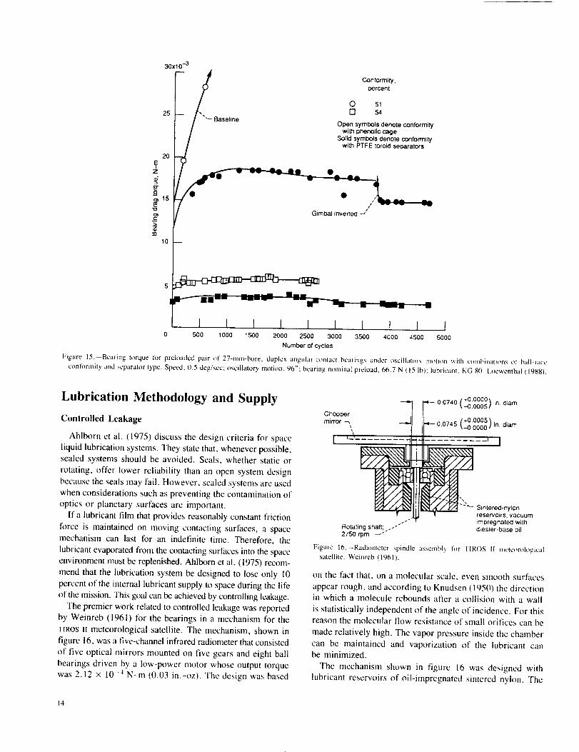
30X10 -3
25
2O
Z
E.o_o= lS
10
"_ Baseline
ConFormity,
percent
O St
[] ._
Open symbols denote conformity
with phenolic cage
Solid symbols denote conformitywith PTFE toroid separators
I
Gimbal Inverted -/
I I I I I I I I I I0 5430 1000 1500 2000 2500 3000 3500 4000 4500 5000
Number of cycles
Figure" 15, Bearing torque for prcloaded pair t)l" 27-ram-bore, duplex angular-comacl hearings under oscillator_, m,fion v, ilh cmnbinati_ms of ball-race
confi)rmity and separator type. Speed, (1.5 deg/sec: oscillatory motion, 960: bearing nominal preload, 66.7 N ( 15 lb): lubricanl, KG 80, I,oewenthal (1988).
Lubrication Methodology and Supply
Controlled Leakage
Ahlborn et al. (1975) discuss the design criteria for space
liquid lubrication systems. They state that, whenever possible,sealed systems should be avoided. Seals, whether static or
rotating, offer lower reliability than an open system design
because the seals may fail. However, sealed systems are usedwhen considerations such as preventing the contamination of
optics or planetary surfaces are important.
If a lubricant film that provides reasonably constant friction
force is maintained on moving contacting surfaces, a spacemechanism can last for an indefinite time. Therefore, the
lubricant evaporated from the contacting surfaces into the spaceenvironment must be replenished. Ahlborn et al. (1975) recom-
mend that the lubrication system be designed to lose only 10
percent of the internal lubricant supply to space during the life
of the mission. This goal can be achieved by controlling leakage.The premier work related to controlled leakage was reported
by Weinreb (1961) lor the bearings in a mechanism for the
TIROS, meteorological satellite. The mechanism, shown infigure 16, was a five-channel infrared radiometer that consisted
of five optical mirrors mounted on five gears and eight ball
bearings driven by a low-power motor whose output torquewas 2.12 × 10 -4 N-m (0.03 in.-oz). The design was based
"_1 7 0.0740 [ +0.0000_ in. diam'_ --0.0005 /
Chopper I_,=- [ +0.0005 '_min'or --, "_l II 0.0745 _---0.0000 ,t in. diam
I '3 ....... -,_ ' I
_i "-_ Sintered-nylon_ reservoirs, vacuum
- impregnated withRotaTing shaft: .-'" diester-base oil2750 rpm _"
Figure 16.--Radi_meter spindle assembly li)r TIROS [l Inete_)rological
satellite. Weinreb (1961L
on the fact that, on a molecular scale, even smooth surfaces
appear rough, and according to Knudsen (1950) the directionin which a molecule rebounds after a collision with a wall
is statistically independent of the angle of incidence. For thisreason the molecular flow resistance of small orifices can be
made relatively high. The vapor pressure inside the chamber
can be maintained and vaporization of the lubricant canbe minimized.
The mechanism shown in figure 16 was designed withlubricant reservoirs of oil-impregnated sintered nylon. The
14

lubricant was a MIL-L-6085A diester oil with a vapor
pressure of approximately 10 .4 torr. When the outside
pressure was below 10-2 torr, a molecular flow occurredaround the shaft through the small clearance. The clearance
was a nominal 0.0127 mm (0.0005 in.). By using the :quation
derived by Knudsen (1950), it was possible to calculate the
rate at which oil escaped from the bearing assembly. Theamount of oil was determined in the reservoirs from the
required life of the satellite and the escape rate of the lubricant.A problem with this type of lubricating system is the potential
of condensing oil vapor on the optical mirrors.Silversher (1970) reports a simplified equation, based on
a modification of kinematic gas theory, that accounts for the
escaping oil vapor loss through an aperture:
M I/2 "a"
w = 0.0583 7rP(_)(];)A
where
w weight loss through aperture, g/see
P vapor pressure of gas, torr
M molecular weight of oil vapor
T temperature of oil vapor, K
a gap width of aperture, cm
f channel length; or escape path, cm
A area of aperture, cm 2
This equation is valid if the ratio f/a is 16 or greater.Several examples of escape paths are shown in figure 17.
Controlled-leakage sealing was augmented by using liquid
lubricants with low vapor pressure. Silversher (1970) reports
that it is sometimes difficult to correlate a high-average-
molecular-weight product with a uniform low vapor pressure.
Many liquid lubricants contain a wide range of molecular
weights. The low-molecular-weight fractions generallyvolatilize first, so that the rate of fluid loss will not necessarily
be constant. This is illustrated in the data of figure 18 (from
Ahlborn et al., 1975). The rate of evaporation is greater from
the porous nylon reservoirs than from the bearing surfaces or
the phenolic cage. As a result Ahlborn et al. (1975) assumethat only 30 percent of the total oil in the reservoirs is availableto lubricate the bearings or other contacting surfaces.
The most extensively documented use of evaporation as a
method for space lubrication was with a medium-speed despinmechanism manufactured by Dornier System GmbH in 1973
(Hostenkamp, 1980). A schematic of the bearing and
lubrication system is shown in figure 12. The launch loads
bypassed the bearings through an off-load device. The
lubrication system for the bearings was a combination of BP
21 I0 grease with BP I l0 base oil (table IV) thinly applied toboth balls and races and the BP 1 l0 base oil impregnated in
porous phenolic cages and nylon reserwfirs. There was
approximately 0.25 g of oil per cage (an effective porosity
of approximately 2.3 percent). Each reservoir contained
t
I
(a)
i 5_a
' T
-J-- Ia
(b)
-f-i(c)
T ag
I
(a) Straight escape padl.
(b) Elbow escape path.
(c) T-shaped escape path.
Figure 17.--Measurahlc escape paths. Silversher {1970).
10-8
10 -@
I0 -I( I
100
0_1 on
beating Oil in nylonreservoirs
Oil in
3henolic cage
I I 190 80
Oil remaining, wt %
70
Figure 18,--Oil evalx_ration rate variations in vacuum at 40 °C. Ahlborn et al.
(1975)
approximately 3.3 g (an effective porosity of approximately
25 percent). The reservoirs (two for each bearing) were placedclose to each bearing, one on the shaft and one on the housing,
to ensure that at least one reservoir was always at a higher
temperature than the bearing. Narrow clearance relative to the
moving counterpart was provided for the aluminum-backedreservoirs to limit oil loss from the immediate bearing vicinity.
Barrier films (Tillan M-2, derived from FX706) were applied
to the clearances to aid in this purpose.A thermal vacuum real-life test of 7 years was successfully
conducted by the European Space Tribology Laboratory
(Parker, 1987). During the 7-year test period the thermalconditions were changed at 4-week intervals to simulate flightconditions; the mechanism speed was 60 rpm. Earth eclipses
were simulated at 6-month intervals. The testing was success-
15

fully continuedfi_ran eighth year but at normal ambienttemperature.
The vacutnn pressure took several years to stabilize because
of continuous outgassing from the mechanism. This outgassingresulted in the pressure substantially increasing during the
wanner test cycles. Residual gas analysis by, mass spectrometrysuggested that a gradual increase m the relative pressure of
hydrocarbons was due to small amounts of oil being released
into the test environment from the mechanism (Parker. 1987).During testing the current demanded by the motor to enable
the speed control system to maintain a constant speed graduallyincreased. This was not, however, attributed to an increase
in friction torque within the mechanism but to aging of themotor rotor's permanent magnets. The thermal distribution
within the mechanism remained substantially constant exceptduring eclipse simulations. Toward the end of these simulations
a small increase in motor power dissipation was detected.
Changes of thermal gradient across the bearings in the various
test modes did not result in any detectable change in mechanism
performance. A one-per-revolution ticking noise was presentduring the early part of the life test. This was attributed to
relaxation of the flexible diaphragm used to preload thebearings (Parker, 1987).
Post-test examination of the dismantled mechanism revealed
its components to be in excellent condition. The oil-lubricated
bearings were virtually like new without any measurable wear.
The oil and grease lubrication was highly satislactory althoughsome oil was lost from the bearings because of the inadequate
application of barrier films. The oil had marginally contam-
inated the power brush and slip ring components without anyadverse effect (Duvall, 1985). In a letter to this author dated
Nov. 1, 1989, H.M. Briscoe, Consultant in Space Mechanisms
and Tribology, Tykes Barn, Great Britain, suggested that theoil film on the slip rings was beneficial because the brush wear
was less than expected. He speculated that oil leakage from
the bearing chamber may be a reasonable means of lubricatingslip rings.
Lubricant-Impregnated Cages
Fleischauer and Hilton (1990) state that the phenolic-based
cage materials commonly used in satellite bearings have
irrepmducible, time-dependent oil absorption properties(fig. 19). These data were obtained from samples that had beenvacuum impregnated with oil and then allowed to soak in the
oil for the times indicated. From the data it appears that the
cage material continuously absorbs oil. This would suggest thatthe phenolic material acts more like an oil sink than a source.
Tyler et al. (1976) suggest that it is possible for lubricant
feed to occur from the phenolic cage to the balls but not from
the phenolic cage to the bearing race lands. Layers of cotton
material in the phenolic are parallel to the bearing race lands.Lubricant teed, they conclude, cannot occur in a direction
perpendicular to these layers. As a result, the lubrication of
the interface must depend on the initial oil coating on the two
Initial sarnpte
.14 _ weight,g
.12
I [] 4.20380
_.10 i-- 0 4.19905
II 0 4.20595II r Vacuummoregna_on
/1--/ w,tn KG 80 o,I.08 _
_- 04
.02 _'" _ extrac[lon in Freon TF
j j f i J0 40 80 120 160 200 400
Soaking lime, days
{a) Vacut, m bake al - 100 °C tbr 24 hr.
(b) Soxhlet exlracti{m in Frcon TF.
{c) VacuUlll imprcgnati{m with KG NO oil.
Figure 19.- Absorption of oil by phenolic rclainers as a function of lilnc.
Fleischauer and Hiltnn (1990L
surfaces. Hence, it may be concluded that long-term effectivelubrication using phenolic cages as lubricant reservoirs can
best be achieved if the cage is ball guided rather than race
guided. However, as previously discussed, ball-guided cagesare more likely to be unstable (Kanncl et al., 1976).
From late 1984 into early 1985 the scanners of the U.S.
Earth Radiation Budget Experiment (ErBE) and NOAA-9
satellites, after several months in orbit, began experiencingproblems (Watson et al., 1985). A motor torque increase was
detected on several of the units. This suggested an impedimentto the tree rotation of the instruments, which were mounted
on a ball bearing assembly. The motor drove the instruments
back and forth at I rps. The scan angle was 176 °. On one
occasion the rotation of an instrument stopped completely. The
torque increase was attributed to the ball bearing assembly.
The operating conditions of the ball bearing assembly wereduplicated in a laboratory bearing endurance test at I0 ; torr.
The bearing was an AISI 440C, 40-ram-bore, angular-contact
ball bearing with 34 balls and a nominal contact angle of 20 °
to 25 °. The preload was 89 N (20 lb). The bearings porous
phenolic cage, which was inner-land guided, was saturated
with Brayco 815Z, a perfluoroalkylether. The phenolic cage
was the only source of liquid lubricant tbr the bearing. Boththe races and the balls were passivated and chemically treatedwith tricresylphosphate (TCP). The test duration was 8.5 million
cycles. The results of these tests revealed ineffective transfer
of lubricant from the phenolic cage to the contacting surfaces.Also, the use of Tee to chemically treat the ball and race
surfaces resulted in the inability of the PFPE to wet the bearingsurfaces (Morales et al., 1986).
Barrier Films
In order to minimize lubricant loss or migration, both from
the bearing and the satellite, creep barrier coating films are
t6

being used on noncontacting bearing surfaces and on thesurfaces of molecular seals. However. normal procedure is
to avoid the application of barrier films within the bearing and
apply them only to escape gaps. The U.S. Naval ResearchLaboratory developed a barrier film for ihstrument bearings.The film, a fluorinated methacrylate, acts as a low-energy
barrier across which most lubricants cannot creep. It is stable
in air to 423 K (302 °F) and in vacuum to 373 K (212 °F).
It outgasses at 373 K (212 °F) at a rate less than 2 × l0 _
g-cm2/sec. Ahlborn et al. (1975) observe that because thereare differences between the various commercial barrier films.
they should be evaluated tbr a specific application before being
used. They observe that some lubricant tbrmations appear to
"poison" the surlilce of the coatings and render themineffective. They state that the mechanical and chemical
stability of these fihns is improved by high-temperature
vacuum baking.
Positive Feed Systems
Large spacecraft, starting with Skylab (fig. 1), have brought
a new set of tribological problems. Smaller spacecraft could
be stabilized by spinning the spacecrali or by using control
jets. Large, extended-mission spacecraft require large controlmoment gyroscopes (CMG's) that are capable of handling the
large slew loads resulting from astronauts moving around the
craft and from changing the orientation. The large CMG'S can
be heavily loaded and operate at high speeds. Small bearings
using lubricant-impregnated cages may no longer suffice fi)rthese units, and positive lubrication of large bearings may be
required. The lubrication system has to be highly reliable but
extremely compact to meet weight and space requirements
(Kannel and Dufrane, 1986).A major tribological challenge is ensuring that the lubricant
gets into the bearing to lubricate the ball-race interfaces.Devices such as centrifugal oilers attached to the rotating shaft
have been successfully used in some applications. Another
method (Glassow, 1976) uses a single-stroke pump immersed
in a vented oil reservoir to pump the lubricant to the bearing.
James (1977) propose; the entirely different approach shown
in figure 20. In this system, a positive commandablelubricator, the reservoir is sealed to prevent lubricant contami-
nation. The degassed lubricant supply is stored in a flexiblemetal bellows. Pressure is maintained by an external spring
pack. Opening the release valve permits oil to inflate an
adjustable-stroke metering bellows. Subsequent closing of therelease valve and opening of the metering valve starts the l]ow
to the applicator. Metering pressure is sufficient to overcomethe characteristic backpressure of the applicator and to providethe desired flow rate. A metering orifice provides flow rate
adjustment capability. The applicator is supported rigidly, in
the space between the outer race and the inner-race-guidedretainer. In a 110-ram-bore bearing with 12.7-mm (0.5-in.)
diameter balls the space is approximately 3.81 ,rim (0.15 in.)
wide. A standoff distance, typically five times the expectedlaunch-induced axial ball movement, separates the applicator
tip from the ball path. A combination of toroida[ tip shape andTeflon coating enables the applicator to support an oil droplet
that spans the standoff distance. In the operating bearing the
passing balls wipe off a portion of the distended hemispherical
droplet. In this manner oil is slowly and unilbrmly transferredfrom the balls to the retainer ball pockets and to both races.
The droplet is continuously replenished by' flow from the
metering system during the 2- to 4-rain relubrication cycle.
The positive commandable lubricator is designed for high-surface-energy oils such as Apiezon C. The high surface
energy of hydrocarbon oils provides the stabilizing force li)rthe lubricant droplet on the applicator tip. The system is best
suited for large bearings, where there is sufficient space
between the retainer dynamic envelope and the race to accept
the applicator (James, 1977).NASa research (Loewentbal et al., 1985) with a terrestrial
experimental 46-cm (19-in.) diameter, 58-kg (128-1b) flywheelshowed the feasibility of using a wick lubrication system ina vacuum environment to lubricate moderate-speed bearings.
The flywheel with its lubrication system is shown in figure 21.In this system a lightly spring-loaded wick saturated with oilcontacts a conical sleeve adjacent to the bearing inner race.
Frictional contact against the sleeve causes a small amount
of oil to be deposited. This oil migrates along the sleeve to
Metering bellows'-m
IAdjustable stop --.,
, jRelease vane-.. "., _
I
_,,,.-_....... H.._'A Delivery tube --/
'.- Lubricantreservoir
L_ Spring pack
m Metering valve
Applicator --,,
LStandoff "*_''_
,-- Rotating
,/ inner race
inner-race-,"/- guided
retainer
Stationary
outer race
Figure 20.--Positive commandable lubricator for satellite bearing application. James (1977).
17

//-- Vacuum line
i oo matic1 piston and.J rotor
!t release
J
Carbon lace seat
Midspansland
bearing -_
\
,- Drive/
// spindle
//
,- Release/
/ coupling
//
//
//
/
/- Spring
// preload/ washers -- /
Elaslomer
bearing
///
I/
iII
II
I1
I
iIII
L Upperrotor
bearing
/ ")-- OilOil reservoir ,( /
" / wick\\ 1 feed
bearing
Lower rotor bearing _'
_L Rotor
Figure 21.--Schematic of NASA flywheel rotor module. Loewcnthal et al. (1985)
CD 90 46861
its large end and into the bearing under the centrifugal forcefield. The wick absorbs oil from the reservoir; the oil travels
through the wick by capillary action to replenish the oil
entering the bearing. In a terrestrial system, because of gravity,
the oil droplets leaving the bearing and the oil vapor that
coalesces against the cooler housing walls eventually returnto the reservoir, thus closing the cycle. Whether condensation
and reuse of the oil can be accomplished in a space systemis an open issue.
The rotor system was operated at speeds from 10 000 to20 000 rpm at absolute housing pressures from 195 down to
45 millitorr. The peak rated power of the flywheel, 120 kW
at 20 000 rpm, corresponds to a maximum discharge torque
of 57 N-m (504 in.-lb). The bearing outer-race temperatureprofiles are shown in figure 22. These data show that the
bearings will operate at lower temperatures when the housingpressure is low: the aerodynamic heating of the rotor is less
at lower pressure. The data confirm that the wick feed systemprovides adequate cooling, particularly at the lower vacuumlevels (Loewenthal et al., 1985).
6O
oo-- I ..C],,. I
Absolute
housing
pressure,millitorr
40-50
85-1 O5
I_O-2oo ,6.-'--'-_/"
=
50 --
® £3- _" O" "_" t31 I I I I30
0 4 8 12 16 20x103
Rotor speed, rpm
Figure 22.--Flywheel lower support bearing temperature characteristics with
speed and housing pressure. Bearing type. 20-ram-bore, deep-groove ball
bearing; thrust load, 712 N (160 Ib). Locwenthal et al. 11985).
18

Concluding Remarks
A search of the literature revealed that spacecraft lubrication
systems have, for the most part, performed adequately over
the past three decades. That is, spacecraft and satellites havereached their required lifetimes without a lubrication-relatedfailure. However, this success was achieved because the life
of satellite systems is generally limited by their batteries,
electronics, and thermal and optical systems. However, as
these technologies are improved, spacecraft systems will
probably become limited by the lubrication system.Problems related to spin-stabilized satellites involve the
despin mechanical assemblies and the slip ring assemblies,which are required to operate with low torque ripple and lowelectrical noise. Tests have verified current designs, and in
many satellites power system failures have occurred beforelubrication failures have surfaced. However, the ability to
control gross bearing torque and noise is essential to achieving
high reliability and long life.
Spin bearings for control moment gyros, operating at speeds
up to 12 000 rpm, have been lubricated successfully for current
design lives with oil-impregnated phenolic cages. Future
systems will require much longer lives as well as higher load
capabilities.Gimbal bearings, which operate in an oscillatory mode and
rarely make a full revolution, are a major concern becauseof the blocking phenomenon and debris buildup discussedherein. Careful consideration must be given to the design and
use of these bearings in order to achieve long lifetimes.
Boundary lubrication with antiwear and extreme-pressureadditives in the lubricant in a satellite (vacuum) environment
is not well defined. There is an issue as to whether these
additives are at all effective in the absence of oxygen. The
role of additives needs to be defined for these applications.
The long-term effects of atomic oxygen and other spaceradiation on lubricant behavior and stability remain unknown.
The effects can be important for space missions longer than
10 years.Alternative cage materials with lower wear rates need to
be considered as replacements for phenolic-base materials,
especially in oscillating bearings, in order to inhibit the buildupof wear debris and the potential jamming of the bearing.
Alternative lubrication systems providing for positive lubri-
cant feed to the contacting surfaces may need to be considered
for future space missions. In addition, alternative lubricants
need to be seriously examined as replacements for the
perfluorinated polyalkylethers (PFP_:) for long-term space
missions.In the fourth decade of the space age tribologists and
aerospace design engineers face continuing challenges to
achieve longer lifetimes with liquid lubrication in space.
Lewis Research CenterNational Aeronautics and Space Administration
Cleveland, Ohio 44135, February 16, 1990
19

References
Ahlborn, G.H.: Hinricks. J.T.; and Perrin, B.J. (1975) Long Life Lubrication
S)stems Paper presented at European Space Tribology Symposium,
Frascati. Ital,,. Apr. 9-11. IAvail. NTIS. 75N22762.)
Baxter, B.H.: and Hall. B.P. (1985) The Use of Perlluoroether Lubricants
in Unprotected Space Environments. Nineteenth Aerospace Mechanisms
Symposium, NASA CP-2371, pp. 179 207.
Beerbov, er, A. (19721 Boundary Lubrication. Scientific and Technical
Application b}_recasts, Dept. of Army. DAHC-19 69-C.
Bisson, E.E (1964) Friction and Bearing Problems in the Vacuum and
Radiation Environrnent of Space. Advanced Bearing Technology, NASA
SP-38, E.E. Bisson and W.J. Anderson. eds., pp. 259-287.
Boring. H.J.; Hintermann, HE.; and Steh[e, G., (1981) TiC-Coated Ball
Bearings lot Spin-Axis Gyro Application. Lubrication Engineering. vol. 37,
no. 9, pp. 534-537.
Boring, H.; Hintermann, H,E.: and Hanni, W., (1987) Ball Bearings with
C VD-TiC Coated Components. Proceedings _(the 3rd European Space
Mcclla_u._m,_ and Triholog 3 Symposium, ESA-SP 279. J. Hunt, ed..
European Space Agency, Paris, France, pp. 155-159.
Buckle',, I) H [1971)Friction. Wear. and Lubrication in Vacuum. NASA
SP 277. pp. t54 158. Buckle v, D,H. (1985)
Carre. D.J ( 1987} The Perlbrmance of Perfluoropo[yalkylether Oils Under
Bt_undary Lubrication Conditions, STLE Paper 87--TC ID-I.
Cheng_ H.S. (1972) Isothermal Elaslohydrodynamic Theory for the Full Range
of Pressure Viscosity Coefficients. Journal of Lubrication Technology,
w_l. 94. no. I, pp. 35 43.
Chiu, Y.P. (1974) An Analysis and Prediction of Lubricant Film Starvation
in Rolling Contact Systems, ASLE Transactions, vol. 17, no. 1. pp. 22-35.
Chmss, F.J. (1961) l,ubricants and Self-Lubricating Materials lot Spacecraft
Mechanisms. Lockheed Aircraft Corp., LMSD-894812. (Avail. NTIS,
AI)-266954.)
Corridan, RE. (1959) Summary Re_rt: Bearing and Lubricant Study.
Advanced Technical Laboratory Division, American Standard Corp.
Coy. J.J.: and Zaretsky, E V. (1981) Some Limitations in Applying Classical
EHD Film Thickness Formulas to a High-Speed Bearing, Journal of
Lubrication Technology, vol. 103, no. 2, pp. 295-304.
Dolan, F.J. ; and McMurtrey, E.L. (1985) Long Term Evaluation of Grease
Type Lubricants in Selected Environments, Man's Permanent Presence in
Space, AIAA, New York.
Dowson. D.; and Higginson, GR. (1966) Elasto-H_'dro_/_'namic Lubrication,
Pergamon Press. London.
Duvalt, J.A. (1985) Report on the Dismantling and Examinatic.n of Dormier
System GmbH Medium Speed Mechanism on Completion of a Seven YearReal Life Test. ESA-ESTL-65.
Feuerstein. S.; and Forster, A.S (1975) A Concept of Despin Mechanical
Assembly Life Testing Involving Total CharactefiTation. SAMSO-TR-75-203.
Fleischauer, P.D.: and Hilton, M.R. (1990) Assessment of the Tribological
Requirements of Advanced Spacecraft Mechanisms. Assessnwnt of the State
_¢ the Art atut Triboh_gy of Advanced Spacecraft Mectumisms, WRDC-
TM-qO 138, 1990.
Flora, D.G., and Haltner, A.J. (1968) Lubricants for the Space Environment,
AIChE Paper 18D. Paper presented at AIChE Symposium on Materials lor
Reentry and Spacecraft Systems--Spacecraft Materials. Part II--Materials
Conference. Philadelphia, PA.
Freundlich, M.M.; and Hannan, C.H. (1%1) Problems of Lubrication in Space,
Lubrication Engineering, vol. 17, no. 2, pp. 72-77.
Glasgow, F.A. (1976) Assurance of Lubricant Supply in Wet-Lubricated Space
Bearing. Proc. lOth Aeros!_we Mechani._tL_ Symposium, NASA CR-148515,
pp. 90 103.
Grubin, A.N. (1949) Fundamentals of the Aertxlynamic Theory, of Lubrication
of Heavily Loaded Cylindrical Surfaces, Chapter 2, Investigation of the Contact
of Machine Counts, Translation of Russian Book No. 30, Central Scientific
Institute for Technology and Mechanical Engineering, Mo._ow, ed., Ketova,
Kh.F. (Available from Department of Scientific and Industrial Research, Great
Britain, Trans., CTS-235 and Special Libraries Asstx:iation, Trans. R 3554.)
Hamrock, B.J.; and Dowson, D. (1977) Isothermal Elastohydrodynamic
Lubrication of Point Contacts. Part Ill--Fully Flooded Results, Journal of
Lubrication Technology, Vol. 99, No. 2, pp. 264 276.
Hamrock, B.J.; and Dowson, D. (1981) Ball Bearing Lz_bricathm: The
Elastohydrodynami(:_ of Elliptical Cantacts, Wiley, NY.
Harris, C.L. (1%9) Vacuum Evaluation of Lubricants and Techniques for Space-
Ext'_)sed Components, ASME Paper 69-LUB 30.
Hostenkamp, R.G. (1980) Design Features of the Dornier Medium Speed
Mechanism. Proceedings of the Secorul Spate Tribology Workshop, ESA
SP-158, G. Levy, ed., European Space Agency, Paris, France, pp. 29-33.
Hunter, S.D.; Kingsbury, E.; and Prahl, J.M. (1987) Oil Film Thickness
Measurement and Analysis for an Angular Contact Ball Bearing Operating in
Parched Elastohydredynamic Lubrication. Svng_._4um on Thin FluM Fibrt_, M.J.
Brown, S. Carmi, and RL. Mullen, eds., ASME, New York, pp. 43-46.
James. G.E. (1977) Positive Commandable Oiler for Satellite Bearing
Lubrication. NASA TM-79356, pp. 87-95.
Jastrow, R. (1960) Lunar and Terrestrial Atmospheres. Advances in the
Astronautical Sciences, Vol. 5, Plenum Press, New York, pp. 338-345.
Jones, W.R.. Jr. (t982) Boundary Lubrication--Revisited, NASA TM-82858.
Jones, W.R., Jr., et al. (1983) Thermal Oxidative Degradation Reactions of
Linear Perfluoroalkyl Ethers, Ind. Eng. Chem. PrtM. Res. Dev., vol. 22, no.
2, pp. 166-170.
Jones, W.R, Jr., et al. (1985) The Effects of Metals and lnhibitors on Thermal
Oxidative Degradation Reactions of Unbranched Perfluoroaklyl Ethers, Ind.
Eng. Chem. Prtxt. Res. Dev., Vol. 24, No. 3, pp. 417-420.
Kannel, J.W.; Bupara, S.S.; and Pentlicki, C.J. (1976) Investigation of Cage
',rod Bearing Instability in Despun Antenna _Bearings Due to Changes in Lubricant
Properties, AFML TR-75 38-PT-2. (Avail. NTIS, AD-A031096.)
Kannel, J.W.; and Dufrane, K.F. (1986) Rolling Element Bearings in Space.
Twentieth Aeroa_we Mechanisms S3_posium, NASA CP 2423, pp. 121-132.
Knudsen, M. (1950) Kinetic Theor)' r_[" Gases; Some Modern A.wects ,
3rd ed. Wiley, NY.
Lammer, J.; Jochimisen, G.: and Hintermann, H.E. (1980) TiC-Coatings
for Bearings in Spacelab-lnstrument-Pointing System, Paper presented at
ASLE-ASME International Lubrication Conference, San Francisco,
Aug. 18-21, 1980.
20

Loewenthal,SH.(1988)TwoGimbalBearingCaseStudies;SomeLessonsLearned.Twenty-Second Aero.wace Mechanisms Symposium, NASA
CP-2506, pp. 253-269.
Loewenthal, S.H.:, Scibbe, H.W.; Parker, J.J.; and Zaretsky, E.V. (1985)
Operating Characteristics of a 0.87 kW-hr Flywheel Energy Storage Module.Proc. 20th bztersociety Energy Conversion Engineering Conference
(IECEC), pp. 164-174.
McKee, F.B. (1987) Gyro Spin Axis Bearing Performance Using Titanium
Carbide Coated Balls, Paper presented at 1983 Ball Bearing Symposium,
Orlando, FL, DOD/lnstrument Bearing Working Group, Mar. 9-12, 1987.
Mceks, C.R., Christy, R.I., and Cunningham, A.C. (1971) Accelerated
Vacuum Testing of Long Life Ball Bearings and Sliprings. Fifth Aerospace
Mechanisms Symposium, NASA SP-282, pp. 127-135.
Morales, W.: Jones, W.R., Jr.; and Buckley, D.H. (1986) Analysis of a
Spacecraft Instrument Ball Bearing Assembly Lubricated by a Perfluoro-
alkylether. NASA TM-87260.
Mori, S.; and Morales, W. (1989a) Degradation and Crosslinking of
Perfiuoroalkyl Polyethers Under X-Ray Irradiation in Ultrahigh Vacuum.
NASA TP-2910.
Mori, S.; and Morales, W. (1989b) Tribological Reactions of Perfluoroalkyl
Polyether Oils With Stainless Steel Under Ultrahigh Vacuum Conditions
at Room Temperature, Wear, vol. 132, 1989, pp. 111-121.
Parker, K. (19871 Seven Year Thermal Vacuum Real Life Test of a Medium
Speed (Despin) Mechanism Manufactured by Dornier System, ESA-
ESTL-64. (Avail. NTIS, 88N17038.)
Phinney, D.D.; Pollard, C.L.; and Henricks, J.T. (1988) Experience With
Duplex Bearings in Narrow Angle Oscillating Applications. Twenty-Second
Aero.space Mechanisms Symposium, NASA CP-2506, pp. 211-226.
Reichenbach, G.S. : Shaw, R., Jr.; and Foster, R.G. (1964) Lubricant Behavior
in High Vacuum, ASLE Transactions, vol. 7, no. I, pp. 82-90.
Robbins, E.J. (1975) Tribology Tests for Satellite Application: Simulation
of the Space Environment, Paper presented at European Space Tribology
Symposium, Frascati, Apr. 9-1 I. (Avail. NTIS, 75N22764.)
Roberts, E.W.; Rowntree, R.A.: and Anderson, J.C. (1990) A Review of
European Trends in Space Tribology and Spacecraft Mechanism Tech-
nology. Assessment of the State of the Art and Tribology of Advanced
Spacecraft Mechanisms, WRDC-TM-90-138, 1990.
Silversher, H.I. (1970) Controlled-Leakage Sealing of Bearings for Fluid
Lubrication in a Space Vacuum Environment, Aerospace Mechani._ms,
Part B. Bearings and Suspensions, vol. 1, G.G. Herzl, ed., J.W. Stacey
Inc., San Francisco, CA, pp. 27-33.
Stevens, K.T. (1983) The Performance of Fomblin Z25 Oil in Ball Bearings
Operating in Vacuum, ESA-ESTL-56. (Avail. NTIS, 85N17150.]
Thomas, A. (1980) Boundary Lubrication of Steel by Various Oils of Low
Vapor Pressure. Proceedings of the Second Space Tribology Workshop,
ESA SP-158. G. Levy, ed., European Space Agency, Paris, France, pp. 6366.
Todd, M.J. (1981) Investigation of Torque Anomaly in Oscillating PDM
Bearings, ESA-ESTL-49. (Avail. NTIS, 83N26091.)
Todd, M .J. ; and Stevens, K.T. (1978) Frictional Torque of Angular Contact
Ball Bearings With Different Conformities. ESA-CR(P)- 122 I, European
Space Agency, Paris, France.
Tyler, J.C.; Brown, R.D.: Carper, H.J.; and Ku, P.M. (1976) Analysis of
Film Thickness Effect in Slow-Speed Lightly-l-x_aded Elastohydrodynamic
Contacts. Part ll--Measurement of Film Thicknesses in Vacuum, AFML
TR-74-189-PT-2. (Avail. NTIS, AD-A021512.)
Uber, J.M. (1985) Analysis of DRIRU Bearings and Lubricant From Solar
Max Repair Mission, SMRM Degradation Study Workshop, NASA
TM-89274, pp. 147-169.
Ward, W., (1984) Evaluation of a 90-mm-Bore Bearing Operating in a
Simulated Space Environment, Lubrication Engr., vol. 40, no. 5,
pp. 290-298.
Watson, ND., et al. (1985) Earth Radiation Budget Experiment (ERBE)
Scanner Instrument Anomaly Investigation, NASA TM-87636.
Weinreb, M.D., (1961) Results of T1ROS II Ball Bearing Operation in Space,
NASA TM X-51354.
Young, W.C.; Clauss, F.J.; and Drake, S.P. (1963) Lubrication of Ball
Bearings for Space Applications, ASLE Transactions, vol. 6, no. 3,
pp. 178-191.
Young, W.C.; and Clauss, F.J. (1966) Lubrication for Spacecraft Application,
Lubrication Engineering, vol. 22, no. 6, pp. 219-227.
Zehe, M.J.; and Faut, 0.D. (1989) Acidic Attack of Perfluorinated Alkyl
Ether Lubricant Molecules by Metal Oxide Surfaces. NASA TM-101962.
21

Nahonal Aeronautics andSpace Adm_n_strahon
I. Report No.
NASA RP- 1240
4. Title and Subtitle
Liquid Lubrication in Space
7. Author(s)
Report Documentation Page
2. Government Accession No.
Erwin V. Zaretsky
9. Performing Organization Name and Address
National Aeronautics and Space Administration
Lewis Research Center
Cleveland, Ohio 44135-3191
12. Sponsoring Agency Name and Address
National Aeronautics and Space Administration
Washington, D.C. 20546-0001
15. Supplementary Notes
3. Recipient's Catalog No.
5. Report Date
July 1990
6. Performing Organization Code
8. Performing Organization Report No
E-5094
10. Work Unit No.
505-63-1B
1. Contract or Grant No.
13. Type of Report and Period Covered
Reference Publication
14, Sponsoring Agency Code
16. Abstract
The requirement for long-term, reliable operation of aerospace mechanisms has, with a few exceptions, pushed
the state of the art in tribology. Space mission life requirements in the early 1960's were generally 6 months to a
year. The proposed U.S. space station scheduled to be launched in the 1990's must be continuously usable for 10
to 20 years. Liquid lubrication systems are generally used for mission life requirements longer than a year.
Although most spacecraft or satellites have reached their required lifetimes without a lubrication-related failure,
the application of liquid lubricants in the space environment presents unique challenges. This report reviews the
state of the art of liquid lubrication in space as well as the problems and their solutions.
17. Key Words (Suggested by Author(s))
Tribology; Lubricants; Space lubrication; Bearings;Liquid lubrication
19 Security Classif. (of this report)
Unclassified
18, Distribution Statement
Unclassified - Unlimited
Subject Category 37
20. Security Classif. (of this page)
Unclassified21. No. of pages
23
NASAFORM1626OCT86 *For sale by the National Technical Information Service, Springfield, Virginia 22161
22. Price*
A03
NASA-_y, 1990

i
