l0 mechanical installation 060210 -...
TRANSCRIPT

L0 Silicon Mechanical Installation
Bill Cooper

Bill Cooper Installation PMG - L0 Mechanical - February 10, 2006 2
L0 Status
• L0 continues to perform well electrically.– Leakage currents and noise levels and are good.
• Leakage currents are 0.1 – 0.2 µA.• Ground isolation and filtering have been
effective.• RTPS works.
– 99.85% of channels work. – Tests with spare modules on cosmic rays
give ~29 ADC counts for minimum ionizing particles, consistent with expectations.
• CMM checks show that the maximum L0 radius is below the design radius of 22.02 mm.
• We are ready to add the L0 installation extensions and to dress cables on them.

Bill Cooper Installation PMG - L0 Mechanical - February 10, 2006 3
L0 Installation Status
• People to serve as back-ups during L0 installation have been assigned.– Primary people are:
• W. Cooper (D0)• M. Roman (PPD Tech Centers, SiDet) • D. Butler (PPD Tech Centers, Lab 3) • J. Howell, Y. Orlov (PPD Mechanical)
– Back-up people are:• H. Lubatti, C. Daly, W. Kuykendall (U. Washington)• R. Wyatt (PPD Tech Centers, Alignment & Metrology) • K. Schultz (PPD Mechanical) • H. Gonzalez (PPD Tech Centers, SiDet)
– Correspondences (person replaced is on the right):• H. Lubatti, C. Daly, J. Howell W. Cooper• R. Wyatt M. Roman• W. Kuykendall, K. Schultz, H. Gonzalez D. Butler• Y. Orlov, W. Cooper J. Howell • J. Howell, W. Cooper Y. Orlov

Bill Cooper Installation PMG - L0 Mechanical - February 10, 2006 4
L0 Installation Status
• Correspondences work provided Y. Orlov, J. Howell, and W. Cooperare not all absent at the same time.
• Rails were aligned using the Brunson and L0 mounts were positioned and epoxied to the ends of the dummy L0 support structure January 23-25 and 27. Joe Howell supervised.– At one end, a limited amount of epoxy should allow removal for an
additional practice.– U. Washington people participated in installation of the first mount.
• A practice installation of L0 was conducted January 30 – February 1 with primaries and those back-ups who had not already participated.– I regret to say that practice did not go well.
• Two of four screws were left out at one of the mounts for the long tool.• The remaining two screws were never tightened.
– That led to a large motion of the far end of the long tool with L0 most of the way in and a decision to halt the practice installation.
• We should have held a refresher installation with primary people first.– That would have helped ensure that installation would go smoothly.– It would also have caught a fixturing problem.

Bill Cooper Installation PMG - L0 Mechanical - February 10, 2006 5
L0 Installation Status
• Primary people spent February 2-3 and 6 checking what had gone wrong.– Steps were repeated at a more leisurely pace and with greater care.– The Brunson and targets on carriages were used to align rails during
two earlier practices, apparently successfully. During our more careful examination, we understood that that method does not provide sufficient precision and contributed to inadequate alignment during the Jan. 30 –Feb. 1 practice. Precision of Brunson measurements of carriages for long tools was judged to be ±3 to ±4 mils.
– We have reverted to the method used during the first August installation. Carriage motions were monitored to establish a starting point for rail alignment, but then the end of the long tool was observed with the Brunson. Motion of that tool end is amplified because of the relatively close separation of carriages during some installation steps (~13”) and the long extension of the tool (~80”).
– Not only did we learn that the rails need to be aligned better, but we also learned that the primary rail was not straight enough. That lack of straightness was corrected by adding shims between the side of the rail and its locating plate.

Bill Cooper Installation PMG - L0 Mechanical - February 10, 2006 6
L0 Installation Status– Having corrected rail alignment and straightness problems, we found
that the end of the long tool tracked its desired position well, ±5 mils horizontally and ±10 mils vertically.
• Procedures will be altered to incorporate these changes.• February 6-7, we proceeded and successfully installed the mock L0
without further alignment problems.• We had been aware of and had investigated an additional issue:
relative centering of Run IIa silicon and the EC beam pipe. Surveys showed that EC beam pipe position can vary ±0.5 mm from one opening / closing survey to the next. Given ~0.5 mm initial misalignment of the beam pipe, we anticipate that relative alignments could differ by ~1 mm. We can accommodate ~5 mm.– Procedures now assume that first end of L0 will be held centered as
insertion begins, but the second end will be allowed to be off the desired insertion line until it and its appendages have cleared the end of the EC beam pipe.
– Once L0 has cleared the EC beam pipe, both ends of L0 will be brought onto the desired insertion line.
Bill Cooper Installation PMG - L0 Mechanical - February 10, 2006 7
L0 Installation Status
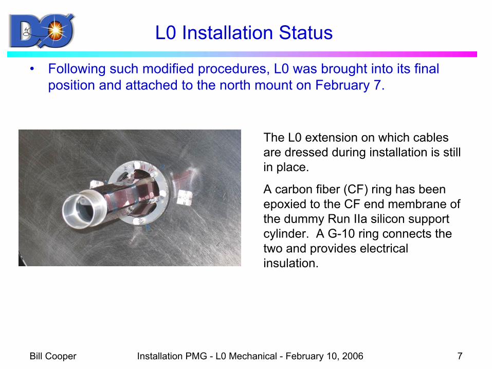
• Following such modified procedures, L0 was brought into its final position and attached to the north mount on February 7.
The L0 extension on which cables are dressed during installation is still in place.
A carbon fiber (CF) ring has been epoxied to the CF end membrane of the dummy Run IIa silicon support cylinder. A G-10 ring connects the two and provides electrical insulation.

Bill Cooper Installation PMG - L0 Mechanical - February 10, 2006 8
L0 Installation Status
• At the south end, we plan to use a G-10 mounting ring which is split into two halves. That accommodates reasonable end-to-end azimuthal misalignment.
• On February 8, a more severe check of azimuthal alignment was made: a full ring was installed on the south end. – That ring went into place without interference.– A subsequent rough check was
made by comparing the changein orientation of a mirror mountedto L0 with the south ball mounts fully tightened and with them loosened. The check indicates an end-to-end azimuthal alignment mismatch of ~0.95 milliradian (~17 µm at the central radius of layer 0b sensors).

Bill Cooper Installation PMG - L0 Mechanical - February 10, 2006 9
L0 Installation Status
• Junction card mounts and the tooling to install them are ready.• Installing the mounts should be quite similar to installing CF end
rings on the Run IIa silicon support structure.• We will verify that
fixturing works, but may wait for all other L0 practices to be completed before epoxyinga mount into place.

Bill Cooper Installation PMG - L0 Mechanical - February 10, 2006 10
L0 Installation Status
• Conclusions from practices:– More practice sessions specific to L0 installation are needed and
planned.• The week of February 13 (primaries)• The week of February 20 (back-ups)
– Work should be careful and methodical.– Distractions should be minimized.– All work should be checked.– To allow verification of steps during L0 insertion, changes should be
made at only one calorimeter end at a time. That was done during earlier trial installations.
– Procedures are being continually updated to take into account what we learn.
– Final procedures should be approved at least a week in advance, reviewed with participants, and then followed.

Bill Cooper Installation PMG - L0 Mechanical - February 10, 2006 11
Removal of Run IIa Beam Pipe
• Removal depends upon many of the same techniques and fixtures as those for the long L0 installation tool.
• The use of rails, carriages, and stages to guide the beam tube was described in past reviews.
• Practice removal of a dummy beam pipe at Lab 3 was started yesterday.
• Methods to connect north and south reference systems are understood.– Cross-hair targets in ends of the beam tube establish a coordinate
system in which openings in outer membranes can be measured.– That allows us to establish an ideal axis through membrane openings.– The Brunson would be used to sight along that axis and to guide motion
of the second end of the beam tube with a target in the end of the tube.• We made the measurements to establish a reference system from
the south end, but ran out of time before repeating them at the north end.

Bill Cooper Installation PMG - L0 Mechanical - February 10, 2006 12
Status of New Beryllium Beam Pipe• Bake-out and leak checks
are being done at PAB by PAB and D0 personnel.
• The stainless steel beam pipe extensions have been baked out at 350o C.
• They have been coupled to the beryllium beam pipe for a final bake-out and leak check at 105o C.
• A helium leak check preliminary to the bake-out showed no detectable leak with a leak detector sensitivity of 4 x 10⁻¹⁰ atm-cc/s.
• The twenty-four hour bake-out was begun yesterday.

Bill Cooper Installation PMG - L0 Mechanical - February 10, 2006 13
Status of Beam Pipe Supports
• Design of beam pipe supports to replace those of the outer H-disks is nearly complete.– Except possibly for Cilran tubing, materials for fabrication are in hand.– Fabrication at Lab 3 should take about a week of uninterrupted effort.– We had hoped that Sasha Leflat would be able to transfer radiation
sensors from outer H-disks to the new beam pipe supports. We have just learned that he cannot come from Russia until later, so we will need to adjust our plans.

Bill Cooper Installation PMG - L0 Mechanical - February 10, 2006 14
Recommendations from the 10/25/05 Director’s Review
• Re-check and measure the gravitational sag of L0.• Response:
– After an incident during which the CMM camera collided with L0, damaging three sensor strips, CMM safety procedures were reviewed jointly by SiDet and D0. New SiDet CMM procedures and L0 measurement procedures were written, reviewed, and adopted.
– A better understanding was developed of the possibility of CMM “run-away” during measurements.
– Software and hardware protections were added to the CMM to address that possibility.
– Implementing those protections delayed the start of measurements and led to a significant increase in the time the measurements took.
– Measurements were completed 1/13/06.– Completion of analysis of the measurements has been delayed to allow
Lab 3 installation tests.

Bill Cooper Installation PMG - L0 Mechanical - February 10, 2006 15
Recommendations from the 10/25/05 Director’s Review
• Quantify and certify, if possible (accelerometers study?), the capabilities of the L0 transportation box to withstand and protect L0 during the transportation. Study and mitigate risks during the human handling of the box in the transportation for SIDET to the D0 Collision Hall.
• Response:– The transport container cannot provide adequate protection if it is
dropped a significant distance. For example, if it were dropped from a height of 30” to the floor, L0 deceleration upon impact would be ~240 g.
– Surrounding the transport container with 12” of foam should decrease that deceleration to ~2 g. That is consistent with the deceleration L0 should be able to tolerate.
– We will provide 12” of padding around the L0 transport container during transport by vehicle and at other times when it is practical.
– Whenever the transport container needs to be carried by hand without padding, two people will carry it, one per carrying handle. Each person will have a neck sling which passes around the transport container and through the appropriate handle.

Bill Cooper Installation PMG - L0 Mechanical - February 10, 2006 16
Recommendations from the 10/25/05 Director’s Review
• Response (continued):– When substantial elevation changes are needed, for example during
final lifting to beam height, a hoist or equivalent will be used. Two people at the upper elevation will hold safety tethers passing around the transport container and through its handles. They will keep the tethers free of excess slack and will be prepared to take the container load. Two additional people will guide the transport container as it is lifted.
Bill Cooper Installation PMG - L0 Mechanical - February 10, 2006 17
Recommendations from the 10/25/05 Director’s Review
• Create a crew of “understudies” through extensive training at the mock-up station to have additional crew(s) available in case some of the major players of the L0 installation (Roman, Butler, etc.) are not available or call in sick for a period during the 14 weeks shutdown. Have major players learn how to supervise the new crew.
• Response:– Back-ups have been assigned.– Training has begun.– More training sessions will be held.

Bill Cooper Installation PMG - L0 Mechanical - February 10, 2006 18
Recommendations from the 10/25/05 Director’s Review
• Installation Procedure (18 pages document) is a super start. Continue its development, adding picture/drawings for explicative purpose, and ensuring that the primary crews and crews-in-training are aware and knowledgeable about all the steps listed.
• Response:– The overall procedures were updated with pictures soon after the
review. That update can be found at: http://d0server1.fnal.gov/projects/run2b/silicon/Layer0/Procedures/L0_insertion/Layer0_Mech_installationProc_11_8.doc
– As we learn from practice sessions, improvements will be incorporated into the procedures.
– Final procedures will be reviewed and approved prior to their use.

Bill Cooper Installation PMG - L0 Mechanical - February 10, 2006 19
Recommendations from the 10/25/05 Director’s Review
• Confirm the time schedule estimates with real-time installation exercises run at the existing L0 mock-up. Run the timing exercises in sequence, performing all the tasks one after the other and understanding the relationship between the end of one task the beginning of the next one. Simulate the D0 installation scenario as much as reasonably possible (i.e. un-installed and un-aligned rails, unglued L0 supports, etc). Feed the results into the main schedule.
• Response:– The full installation scenario, including aligning rails and gluing L0
supports, was tried.• Times for the individual tasks were reasonably consistent with the schedule.• Four days to set up and glue L0 supports (5 days scheduled)• Two days to set up and insert L0 after five days discovering and remedying
problems (5 days scheduled)– We will try to satisfy the recommendation regarding timing with tasks
run one after the other, but may need to defer that until we have ensured that installation procedures are optimized.

Bill Cooper Installation PMG - L0 Mechanical - February 10, 2006 20
Recommendations from the 10/25/05 Director’s Review
• Work with the PPD management and the Directorate to develop a reporting methodology that allows the Lab management to look at the schedule developments at a level deeper than the ~20 official milestones reported during the review.
• Response:– George Ginther or Rich Smith will address this.

Bill Cooper Installation PMG - L0 Mechanical - February 10, 2006 21
Recommendations from the 10/25/05 Director’s Review
• Within reason and limits, explore what-if scenarios that could hinder the L0 installation. Examples:– G10 disks for L0 mounts. Have extra available and ready for machining
if the L0 supports are glued in the wrong position.– Have the present beam pipe stored away and ready for re-installation if
anything happened to the L0 beam-pipe.– Make sure PPD ES&H personnel is on call day #1 of the shutdown for
un-expected contamination issues.• Response:
– We have checked surveys of EC alignment, concluded there could be an issue, and addressed it.
– Extra connecting rings will be available.– We had planned to store and purge the present beam pipe. Its storage
box is at D0.– Discussions have been held with Eric McHugh (PPD ES&H).
• He expects to be available when needed.• Beryllium handling training will be required. • Wipes will be made of the beam pipe at the first opportunity. • Should the wipes be acceptable, no unusual measures would be required.• If they are not, it may be necessary to clean the beam pipe as it is removed.