l03 - applying integrated architecture features to … · improve industrial control system (ics)...
TRANSCRIPT

L03 - Applying Integrated Architecture® Features to Improve Industrial Control System (ICS) Security
For Classroom Use Only!

Important User Information
This documentation, whether, illustrative, printed, “online” or electronic (hereinafter “Documentation”) is intended for use only as a learning aid when using Rockwell Automation approved demonstration hardware, software and firmware. The Documentation should only be used as a learning tool by qualified professionals. The variety of uses for the hardware, software and firmware (hereinafter “Products”) described in this Documentation, mandates that those responsible for the application and use of those Products must satisfy themselves that all necessary steps have been taken to ensure that each application and actual use meets all performance and safety requirements, including any applicable laws, regulations, codes and standards in addition to any applicable technical documents. In no event will Rockwell Automation, Inc., or any of its affiliate or subsidiary companies (hereinafter “Rockwell Automation”) be responsible or liable for any indirect or consequential damages resulting from the use or application of the Products described in this Documentation. Rockwell Automation does not assume responsibility or liability for damages of any kind based on the alleged use of, or reliance on, this Documentation. No patent liability is assumed by Rockwell Automation with respect to use of information, circuits, equipment, or software described in the Documentation.
Except as specifically agreed in writing as part of a maintenance or support contract, equipment users are responsible for:
• properly using, calibrating, operating, monitoring and maintaining all Products consistent with all Rockwell Automation
or third-party provided instructions, warnings, recommendations and documentation;
• ensuring that only properly trained personnel use, operate and maintain the Products at all times;
• staying informed of all Product updates and alerts and implementing all updates and fixes; and • all other factors affecting the Products that are outside of the direct control of Rockwell Automation.
Reproduction of the contents of the Documentation, in whole or in part, without written permission of Rockwell Automation is prohibited. Throughout this manual we use the following notes to make you aware of safety considerations:
Identifies information about practices or circumstances that can cause an explosion in a hazardous environment, which may lead to personal injury or death, property damage, or economic loss.
Identifies information that is critical for successful application and understanding of the product.
Identifies information about practices or circumstances that can lead to personal injury or death, property damage, or economic loss. Attentions help you: • identify a hazard • avoid a hazard • recognize the consequence
Labels may be located on or inside the drive to alert people that dangerous voltage may be present.
Labels may be located on or inside the drive to alert people that surfaces may be dangerous temperatures.
N999 – Your lab title goes here
Presenter: <<Your name>> <<Your business group>>
3 of 130
Applying Integrated Architecture® Features to Improve Industrial Control System (ICS) Security
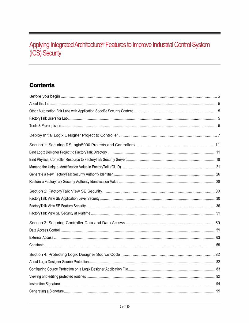
Contents
Before you begin ........................................................................................................................................... 5
About this lab .................................................................................................................................................................................... 5
Other Automation Fair Labs with Application Specific Security Content ........................................................................................... 5
FactoryTalk Users for Lab ................................................................................................................................................................. 5
Tools & Prerequisites ........................................................................................................................................................................ 5
Deploy Initial Logix Designer Project to Controller ....................................................................................... 7
Section 1: Securing RSLogix5000 Projects and Controllers ....................................................................... 11
Bind Logix Designer Project to FactoryTalk Directory .................................................................................................................... 11
Bind Physical Controller Resource to FactoryTalk Security Server ................................................................................................ 18
Manage the Unique Identification Value in FactoryTalk (GUID) ..................................................................................................... 21
Generate a New FactoryTalk Security Authority Identifier .............................................................................................................. 26
Restore a FactoryTalk Security Authority Identification Value ........................................................................................................ 28
Section 2: FactoryTalk View SE Security .................................................................................................... 30
FactoryTalk View SE Application Level Security ............................................................................................................................ 30
FactoryTalk View SE Feature Security ........................................................................................................................................... 36
FactoryTalk View SE Security at Runtime ...................................................................................................................................... 51
Section 3: Securing Controller Data and Data Access ............................................................................... 59
Data Access Control ....................................................................................................................................................................... 59
External Access .............................................................................................................................................................................. 63
Constants ........................................................................................................................................................................................ 69
Section 4: Protecting Logix Designer Source Code .................................................................................... 82
About Logix Designer Source Protection ........................................................................................................................................ 82
Configuring Source Protection on a Logix Designer Application File .............................................................................................. 83
Viewing and editing protected routines ........................................................................................................................................... 92
Instruction Signature ....................................................................................................................................................................... 94
Generating a Signature ................................................................................................................................................................... 95

4 of 130
Modifying a “Signed” AOI ................................................................................................................................................................ 98
Getting Signature Information in Code .......................................................................................................................................... 100
Distributing/Reusing a Protected/Signed AOI ............................................................................................................................... 104
Section 5: Change Management for ControlLogix Programmable Automation Controllers ..................... 110
ControlLogix Change Detection .................................................................................................................................................... 110
FactoryTalk AssetCentre Audit Logging ....................................................................................................................................... 115
FactoryTalk AssetCentre Audit Log Reporting .............................................................................................................................. 116
Automated Controller Change Monitoring with FactoryTalk AssetCentre ..................................................................................... 120

5 of 130
Before you begin
About this lab
Learn how to protect your ControlLogix™ programmable automation controller (PAC) against emerging security threats utilizing
FactoryTalk® Security technology.
This lab will walk you through practical ways to protect the intellectual property contained in your ControlLogix PAC, manage
access control to your control system hardware and software, and improve tamper resistance. This includes the application of
FactoryTalk Security, Logix Designer® Source Protection, Logix Designer Data Access Protection. Additional appendices of this
hands-on lab walk through how to leverage FactoryTalk Security in FactoryTalk View Site Edition® applications and leverage
FactoryTalk AssetCentre® for additional access control to your industrial control system.
This lab takes approximately 90 minutes to complete.
Other Automation Fair Labs with Application Specific Security Content
L06 – FactoryTalk® View Site Edition: Building Applications
L11 – FactoryTalk® View Machine Edition and PanelView™ Plus: Introductory Lab
L18 – Rockwell Software Studio 5000® and Logix Advanced Lab
FactoryTalk Users for Lab
The FactoryTalk Users in this lab can be only be used to login to FactoryTalk, not Windows. There are features within
FactoryTalk Security to link FactoryTalk Users to Local Windows or Microsoft Active Directory accounts and groups. For this lab
we will be using and configuring access for the following FactoryTalk users:
User Name Password Group Membership
Administrator rockwell Administrators
Denied rockwell No Access
Engineer rockwell Engineers
Maintenance rockwell Maintenance
Operator rockwell Operators
Supervisor rockwell Supervisors
Tools & Prerequisites
Software programs required
The following software is required to complete this lab.
VMware Workstation v10
FactoryTalk Services Platform v2.60 (CPR 9 SR 6)
FactoryTalk View Site Edition v7.00 (CPR 9 SR 6)
RSLinx Enterprise v5.60.00 (CPR 9 SR 6)
6 of 130
RSSecurity Emulator 2.60 (CPR 9 SR 6)
(Installed from the FactoryTalk Tools program files folder in the Start Menu)
Logix Designer v20.01 (CPR 9 SR 5)
RSLinx Classic v3.60 (CPR 9 SR 6)
FactoryTalk AssetCentre v5.00 (CPR 9 SR 6)
Microsoft SQL Server 2008 R2
Hardware devices required
The following hardware is required for this lab.
1756-A4 ControlLogix Chassis
1756-EN2T or 1756-ENBT ControlLogix Ethernet Bridge (192.168.1.113) (Slot 0)
1756-L75 ControlLogix PLC (Slot 1) with v23 Firmware
You can use the ENET11, ENET21, CL31, or HART Rockwell Automation Demo Kits for this lab.
Files required
The following files are required to complete this lab.
VMware image files for the Automation Fair 2014 NW17 hands-on lab
IF2_Demo.ACD project file for RSLogix5000
(Stored in FactoryTalk AssetCentre Archive within image under the InstantFizz container)
InstantFizz_HMI project files for FactoryTalk View SE
(Stored in FactoryTalk AssetCentre Archive within image under the InstantFizz container)
7 of 130
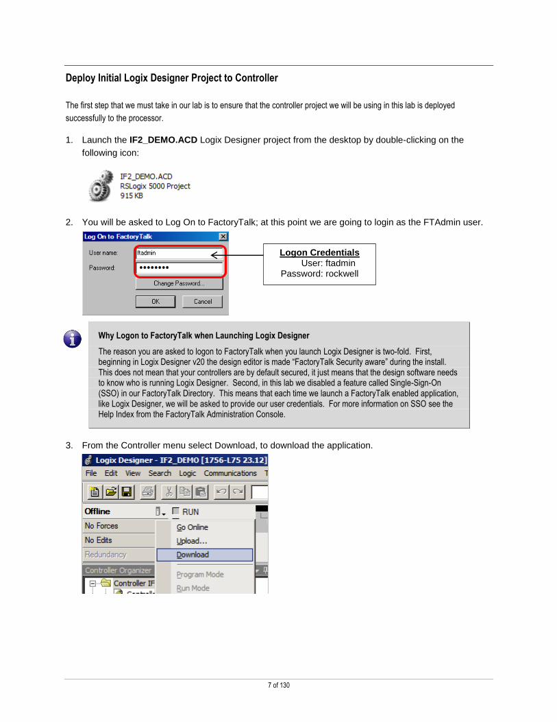
Deploy Initial Logix Designer Project to Controller
The first step that we must take in our lab is to ensure that the controller project we will be using in this lab is deployed
successfully to the processor.
1. Launch the IF2_DEMO.ACD Logix Designer project from the desktop by double-clicking on the
following icon:
2. You will be asked to Log On to FactoryTalk; at this point we are going to login as the FTAdmin user.
Why Logon to FactoryTalk when Launching Logix Designer
The reason you are asked to logon to FactoryTalk when you launch Logix Designer is two-fold. First, beginning in Logix Designer v20 the design editor is made “FactoryTalk Security aware” during the install. This does not mean that your controllers are by default secured, it just means that the design software needs to know who is running Logix Designer. Second, in this lab we disabled a feature called Single-Sign-On (SSO) in our FactoryTalk Directory. This means that each time we launch a FactoryTalk enabled application, like Logix Designer, we will be asked to provide our user credentials. For more information on SSO see the Help Index from the FactoryTalk Administration Console.
3. From the Controller menu select Download, to download the application.
Logon Credentials User: ftadmin
Password: rockwell

8 of 130
4. Click the button that says Download to download this application to the controller
Quick Tip: Take notice that the area boxed in blue. This indicates to us that the controller currently is not secured. We will review later what it looks like when the controller is secured.
5. Once the application has successfully downloaded, it should ask you to return the controller to
Remote Run. Click Yes
9 of 130
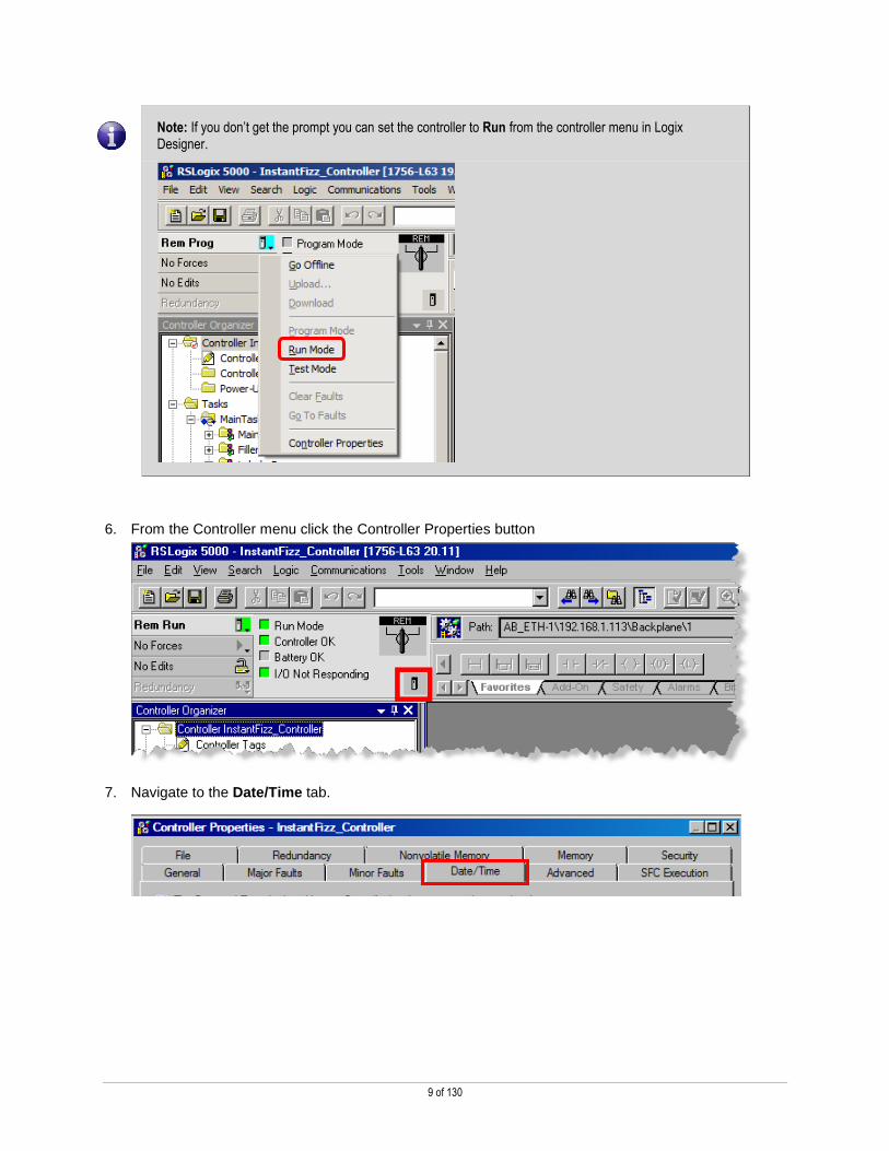
Note: If you don’t get the prompt you can set the controller to Run from the controller menu in Logix Designer.
6. From the Controller menu click the Controller Properties button
7. Navigate to the Date/Time tab.

10 of 130
8. Click the button that says, Set Date, Time, and Zone from Workstation (Circled in Red below).
9. Click OK to apply these changes.

11 of 130
Section 1: Securing RSLogix5000 Projects and Controllers
The following section of the lab will explain how to secure both Logix Designer project files and Programmable Automation
Controller (PAC) hardware resources to the FactoryTalk Directory.
This section takes approximately 20 minutes to complete.
Bind Logix Designer Project to FactoryTalk Directory
The first step in securing resources to the FactoryTalk Security model is to enable the FactoryTalk Security binding in the Logix
Designer project file.
Design Note: Security binding is on a resource basis. You must enable each project in your system to communicate with the FactoryTalk directory security model, then link the resource in the FactoryTalk Directory using the steps below.
1. Click on the Controller Properties button shown below circle in red:
12 of 130
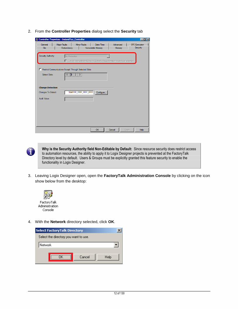
2. From the Controller Properties dialog select the Security tab
Why is the Security Authority field Non-Editable by Default: Since resource security does restrict access to automation resources, the ability to apply it to Logix Designer projects is prevented at the FactoryTalk Directory level by default. Users & Groups must be explicitly granted this feature security to enable the functionality in Logix Designer.
3. Leaving Logix Designer open, open the FactoryTalk Administration Console by clicking on the icon
show below from the desktop:
4. With the Network directory selected, click OK.
13 of 130
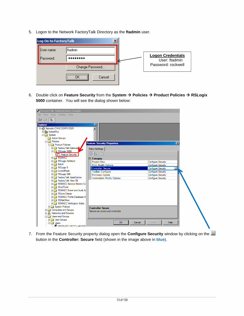
5. Logon to the Network FactoryTalk Directory as the ftadmin user.
6. Double click on Feature Security from the System Policies Product Policies RSLogix
5000 container. You will see the dialog shown below:
7. From the Feature Security property dialog open the Configure Security window by clicking on the
button in the Controller: Secure field (shown in the image above in blue).
Logon Credentials User: ftadmin
Password: rockwell

14 of 130
8. Notice in the Securable Action dialog below that the only group with privileges to secure a controller is
our Engineers group. Therefore we need to login to Logix Designer as the engineer user.
9. Click Cancel on both open windows to close the security configuration windows.
10. Switch back over to Logix Designer.
11. From the Logix Designer Tools Security menu select Log On...
12. Log in as the engineer user (password: rockwell)

15 of 130
13. If you have the Controller Properties window open you will see that the Security Authority field
becomes editable once we login as the engineer user.
14. From the drop down menu select FactoryTalk Security (FTSEC-DEMO14) and click OK to apply this
change to the project after taking notice of the callouts below.
Design Tip: The Use only the selected Security Authority for Authentication and Authorization box requires that the unique identification key (GUID) of the FactoryTalk Security server selected match the value encrypted in this project. We will learn more about this value in the next section.
Notice where it says ftsec-demo14, this is the name of our directory and security server. Starting in Logix Designer v20, resource based security is bound to specific FactoryTalk Directory & Security server.

16 of 130
15. After clicking OK, applying the security configuration for this project, you will receive a dialog alerting
you that applying security will result in a loss of some privileges, acknowledge this warning by clicking
Yes.
16. From the Controller menu select Download, to download the application.
Note: If you were already online and made this change you will not need to re-download to the controller.
17. From the Download dialog take notice that the processor we are downloading to currently is not
security enabled, circled in blue below, and click Download.

17 of 130
18. Once the download completes, you will be asked to change the controller back to Remote Run, click
Yes to initialize the project.
19. Click the save button to apply our changes to the project. If prompted, click Yes to upload tag
values.
20. Close Logix Designer.
21. Once Logix Designer closes, open the IF2_DEMO.acd application again by double clicking the icon
on the desktop.
22. Logon as the denied user (password: rockwell).
23. You should see the message window displayed below that informs the user they are not authorized to
open this project according to our security policy.
24. Click OK to close the dialog and exit Logix Designer.
Logon Credentials User: denied Password: rockwell

18 of 130
Bind Physical Controller Resource to FactoryTalk Security Server
Now that we have configured both FactoryTalk Security and secured our Logix Designer project file we need to bind the newly
secured controller resource to our FactoryTalk Directory server to protect it from unauthorized connections.
1. Toggle back to the FactoryTalk Administration Console
2. Log into the FactoryTalk Administration Console as the ftadmin user.
3. Expand out Networks and Devices Workstation, FTSEC-DEMO14 AB_ETH-1,Ethernet
192.168.1.113 Backplane. Right click on the 1,1756-L75 LOGIX5575, IF2_DEMO resource and
select Properties…

19 of 130
4. From the Logical name: field select newly created IF2_DEMO item from the drop down list and click
OK. This logical name was created by Logix Designer when we bound the project to FactoryTalk
Security.
Design Tip: Logical Names can be assigned like above or to a specific area, such as an HMI Area controller and used for things like resource & action groups.
FactoryTalk uses these logical name assignments to link a resource on the network to the FactoryTalk Directory.
We have now secured our directory, project, and physical controller resources.
5. From the Networks and Devices Workstation, FTSEC-DEMO14 AB_ETH-1 192.168.1.113
Backplane, right-click on the 1756-L75 LOGIX5575, IF2_DEMO resource and select Security…
6. From the Security Settings windows select the Operators group from the top window, expand the
RSLogix5000 container and scroll down to the permission, Project: Download.
See next page for screenshot of above action

20 of 130
You will notice on our IF2_DEMO resource our Operators group does not have permission to
download to this controller.
7. Click Cancel to close the security dialog, and minimize the FactoryTalk Administration Console.
Verification that the Controller Resource is Secured
We are now going to login to Logix Designer as the operator user and verify secured actions to the controller resource,
IF2_DEMO.
1. Open IF2_DEMO.ACD from the desktop by clicking on the icon that looks like the one below.
2. Logon as operator (password: rockwell.
Logon Credentials User: operator Password: rockwell

21 of 130
3. From the Controller Status, notice that the Download option is greyed out, as we do not have
permission to download to the selected controller resource.
4. Close Logix Designer
We have now successfully verified the security on the controller asset and Logix Designer project file.
Manage the Unique Identification Value in FactoryTalk (GUID)
The following section will explain the implications of binding Logix Designer projects exclusively to a specific FactoryTalk Security
server by the unique identification key (GUID) of your FactoryTalk Security servers.
1. Toggle back to the FactoryTalk Administration Console
2. From the Tools menu select the FactoryTalk Security Authority Identifier…

22 of 130
3. From the Security Authority Identifier Window click on Backup to retain a copy of our current ID value.
4. From the backup window leave the name set to the default, but change the location of the backup file
to the Desktop (C:\Users\Labuser\Desktop) and click OK to create the backup.
WARNING: Prior to binding Logix Designer applications to a FactoryTalk Security server, you must backup the FactoryTalk Directory, as we just did, to ensure you retain a copy of this ID value. In the event the FactoryTalk Security and Directory server is lost, this ID value must be restored to access the bound applications.
If you do not have a backup of the ID you bind to controller resources, there is no way to recover the ID and go online with the secured controller.

23 of 130
5. Once the backup process completes, click OK in the success dialog, but leave the Security Authority
Identifier dialog open.
6. Looking back at Logix Designer select the Log On… option from the Tools Security Menu.
7. Logon as engineer using the password: rockwell.
8. Left-click on the Controller Properties button shown below circle in red:
Logon Credentials User: engineer Password: rockwell
24 of 130
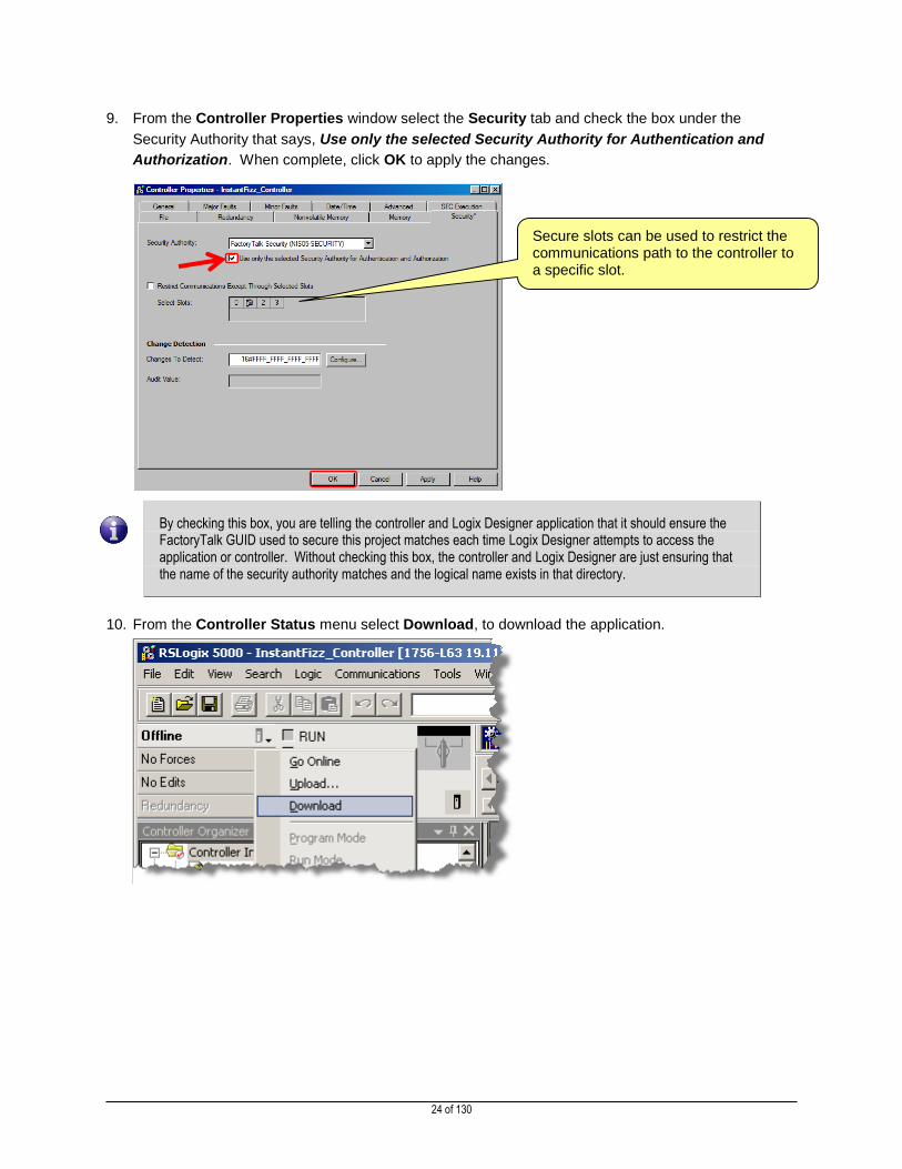
9. From the Controller Properties window select the Security tab and check the box under the
Security Authority that says, Use only the selected Security Authority for Authentication and
Authorization. When complete, click OK to apply the changes.
By checking this box, you are telling the controller and Logix Designer application that it should ensure the FactoryTalk GUID used to secure this project matches each time Logix Designer attempts to access the application or controller. Without checking this box, the controller and Logix Designer are just ensuring that the name of the security authority matches and the logical name exists in that directory.
10. From the Controller Status menu select Download, to download the application.
Secure slots can be used to restrict the communications path to the controller to a specific slot.

25 of 130
11. From the Download dialog take notice that our processor now indicates that it is indeed bound to our
security server, circled in blue below, and click Download.
12. Once the download completes, you will be asked to change the controller back to Remote Run, click
Yes to initialize the project.
13. Click the save button to apply our changes to the project, and click Yes if prompted to upload tag
values.
14. Close Logix Designer.

26 of 130
Generate a New FactoryTalk Security Authority Identifier
Looking back at the FactoryTalk Administration Console we are now going to simulate a FactoryTalk Security server failure by
changing the unique identifier of our FactoryTalk Directory and Security server.
1. Switch back to the FactoryTalk Administration Console, we should be logged on ftadmin.
2. If the Security Authority dialog is not currently open, open it from the Tools menu FactoryTalk
Security Authority Identifier…
3. Click on the Generate ID button from the Security Authority dialog.
4. You will next be asked to confirm this decision, take note of the very important warning message and
click Yes to continue.
5. After the action completes take note of the new ID value circled in blue below, then close the open
dialogs but leave the FactoryTalk Administration Console open.
The ID that is generated on your system may be different since the GUID is created by a randomizer.

27 of 130
6. Open Logix Designer once again logon as our engineering user.
7. Logon as engineer using the password, rockwell.
8. You should see the below dialog indicating that the security ID of the FactoryTalk Security server
does not match the value in the controller project, therefore Logix Designer cannot open the project.
9. Click the OK button the above dialog
10. Close Logix Designer.
Design Tip: If we did not have the exclusive binding box checked in the controller property dialog and change the unique ID of our FactoryTalk Security server, we would have been authorized to open this project because the name of the FactoryTalk Security server remained the same. If the name of your FactoryTalk Security server changes and you secured projects and controller resources in Logix Designer you will see this same error when you try to open a secured project.
Logon Credentials User: engineer Password: rockwell

28 of 130
Restore a FactoryTalk Security Authority Identification Value
Now that we have simulated a failure in our FactoryTalk Security server by changing the unique ID we are going to walk through
how to restore functionality from the backup that we created.
1. Looking back at the FactoryTalk Administration Console, select FactoryTalk Security Authority
Identifier… from the Tools menu.
2. Click Restore from the Modify Security Authority Identifier dialog.
3. From the Restore dialog browse to our backup file located on the Desktop:
(C:\Users\Labuser\Desktop\Network – 6739169-2578-4849-A.bak)
4. Click the Next button to proceed.
29 of 130
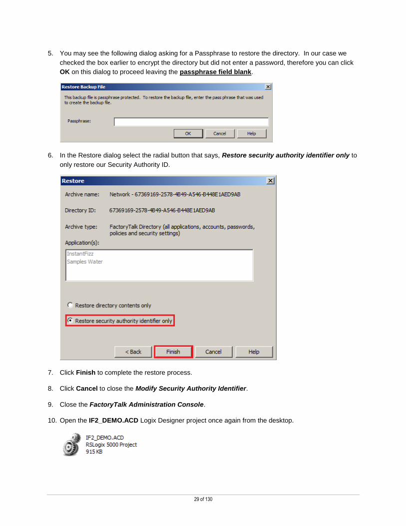
5. You may see the following dialog asking for a Passphrase to restore the directory. In our case we
checked the box earlier to encrypt the directory but did not enter a password, therefore you can click
OK on this dialog to proceed leaving the passphrase field blank.
6. In the Restore dialog select the radial button that says, Restore security authority identifier only to
only restore our Security Authority ID.
7. Click Finish to complete the restore process.
8. Click Cancel to close the Modify Security Authority Identifier.
9. Close the FactoryTalk Administration Console.
10. Open the IF2_DEMO.ACD Logix Designer project once again from the desktop.

30 of 130
11. Logon as engineer using the password, rockwell.
Logix Designer will now successfully open and we have fully secured both our design editor (Logix
Designer), our application file (IF2_DEMO.ACD), and our physical controller to a single FactoryTalk
Security Authority.
12. Close Logix Designer
This completes the Logix Designer Security integration with FactoryTalk Security section of this lab.
Section 2: FactoryTalk View SE Security
FactoryTalk View Site Edition (SE) uses the same security accounts that have been configured within the FactoryTalk Directory
that we use for Logix Designer, allowing the ability to assign specific FactoryTalk View SE actions to existing users. This portion
of the lab will review how to configure some of these basic security options, and then interact with them at client runtime.
This section takes approximately 30 minutes to complete.
FactoryTalk View SE Application Level Security
This section will walk through how to configure application-level security for a FactoryTalk View SE application. Application-level
FactoryTalk View SE security encompasses two main areas: the ability to access the application in general (i.e., read access),
and tag write. The tag write permission applies to any data server communications as a whole, meaning that users are either
granted or denied tag write ability for the entire application.
Launch FactoryTalk View Studio
The goal of this section is to demonstrate how denied application read access appears to the user.
1. Launch the FactoryTalk View Studio shortcut from the desktop, or at All Programs Rockwell
Software FactoryTalk View FactoryTalk View Studio
Logon Credentials User: engineer Password: rockwell

31 of 130
2. Select View Site Edition (Network Distributed) and click Continue
3. Login in as our engineering user, engineer (password: rockwell)
4. Select the InstantFizz application and click Open
5. The following error is displayed:
Logon Credentials User: engineer Password: rockwell

32 of 130
And the follow message in the message display:
The engineer does not currently have access to read the application, which blocks FactoryTalk View Studio from
launching the application at all. The next section of the lab will show how to allow access to this user.
6. Click OK to clear the error and Cancel on the Open dialog. FactoryTalk View Studio will now load
the FactoryTalk Network Directory, but not the View application.
Administer FactoryTalk Application Security
The goal of this section is to allow read access to the Operators and Supervisor, restrict tag-write access to the No Access users,
and grant read-write access to the Engineers users.
1. Looking at FactoryTalk View Studio, note that the InstantFizz application is not currently listed in the
FactoryTalk tree:
2. Because the engineer cannot access the application, a different user will have to log in to access the
application security. Log off and log in as our admin user, ftadmin (password: rockwell), from the
File menu of the FactoryTalk View Studio.
Logon Credentials User: ftadmin
Password: rockwell

33 of 130
3. Select InstantFizz from the Open dialog and click Open.
4. Right-click on the InstantFizz application and select Security.

34 of 130
5. Select the Engineers user group from the upper field.
Design Tip: All Actions have been denied to this user in the InstantFizz application. Even though at the higher Network level this users has been granted these privileges, as indicated by the grey check in the Allow column, the denial at the InstantFizz level takes precedence. Explicit denials always take precedence over explicit allows in FactoryTalk Security, deny with care.
6. Uncheck the Deny checkboxes All Actions. The engineer will now inherit its permissions from the
Network container, which allows all privileges except managing security.
7. Check the Allow box next to All Actions. This grants our engineer full access to the application.
Design Tip: We have granted our Engineer user all rights to the application, including configuring application security. If we DID NOT check the Allow - All Actions box our Engineer user in the following section would receive the below error when trying to modify Runtime Security in FactoryTalk View:
Uncheck this box.
Check this box.

35 of 130
8. Click OK to close the Security dialog for the InstantFizz application.
Open FactoryTalk View SE Application
The goal of this section is to open the application with the newly restored read access.
1. From the file menu, select Log off, and click Yes to close the open application
2. From the file menu, select Log on
3. Login in as our engineering user, engineer (password: rockwell)
4. Select the InstantFizz application and click Open
5. With the proper security privileges in place, the application will now successfully load.
Logon Credentials User: engineer Password: rockwell

36 of 130
FactoryTalk View SE Feature Security
This section will demonstrate how to assign security levels to FactoryTalk users, and then define how those levels relate to
feature options within FactoryTalk View SE. Four levels of feature security will be covered: display level security, object level
security, tag level security, and command level security.
Configure FactoryTalk View Security Codes
1. With the InstantFizz application open, navigate to Runtime Security in the tree and double-click on it.
2. A list of all currently configured users will appear in the lower pane:
Design Tip: This list identifies the users that have been configured for use with this FactoryTalk View SE application. While FactoryTalk View SE security makes use of the accounts created in the FactoryTalk Directory, it does not automatically import these accounts until the user has specifically configured them.
The ‘All Users’ group is automatically configured here by default. We have to now configure our user groups and assign their
access levels.
3. To configure a new user, click the Security Accounts button.

37 of 130
4. The familiar Security Settings dialog will appear.
5. Select the All Users group and click Remove
6. Push the button
7. Select the Supervisors group and click OK to add them to the security list.
Note: Our current user, engineer, is not listed here yet he is logged into this project in View Studio. That is because the settings above are for Runtime HMI project security, the engineer is inheriting permissions to manage View Studio from the FactoryTalk Directory privileges the Engineers group was granted.
38 of 130
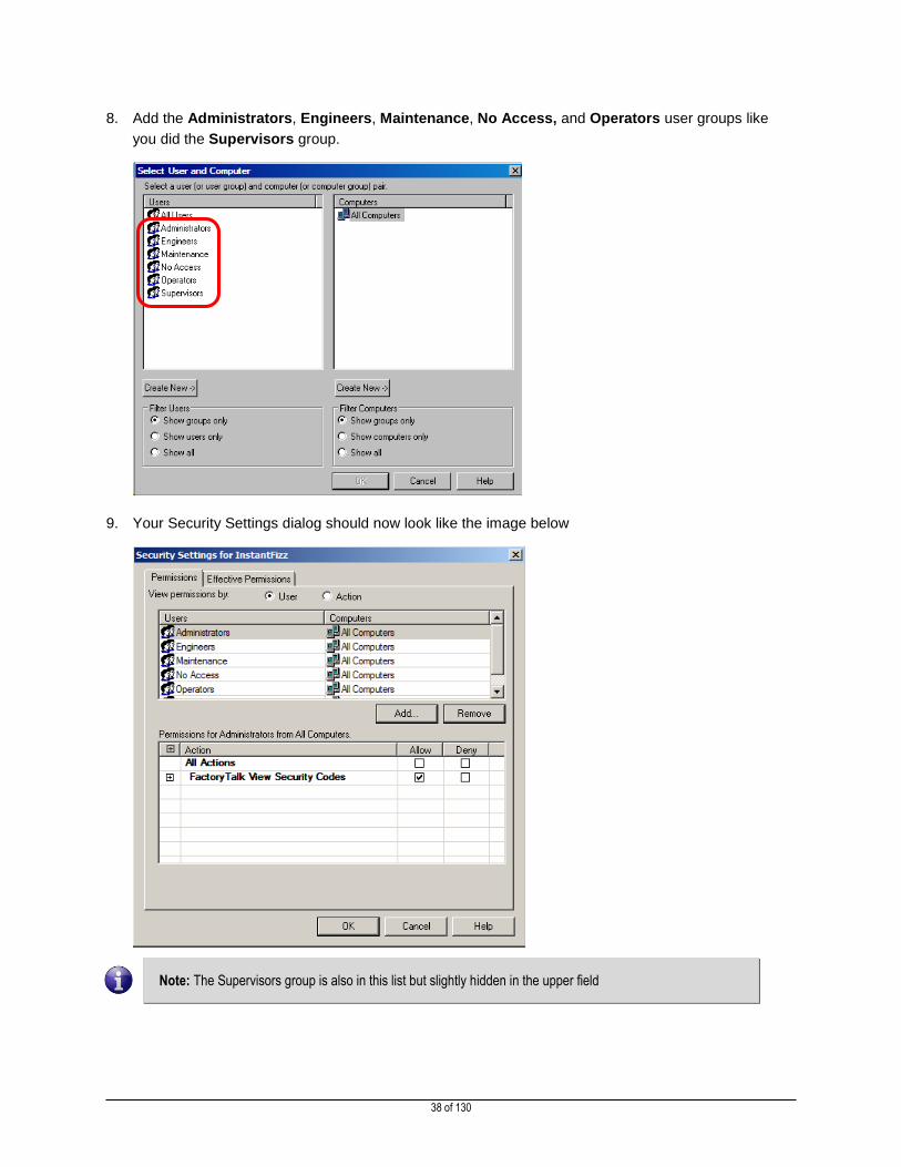
8. Add the Administrators, Engineers, Maintenance, No Access, and Operators user groups like
you did the Supervisors group.
9. Your Security Settings dialog should now look like the image below
Note: The Supervisors group is also in this list but slightly hidden in the upper field

39 of 130
10. Select the Operators group. In the lower pane, under All Actions, Expand the FactoryTalk View
Security Codes heading.
FactoryTalk View Security Codes In FactoryTalk View, run-time access restrictions can be applied to commands and macros, graphic displays, OLE object verbs, and HMI tags. To do this, FactoryTalk View security codes are assigned to the desired components, and then configured for individual users and/or user groups to define the account permissions.
There are 16 FactoryTalk View run-time security codes, A through P, and the asterisk symbol (*). The asterisk symbol represents all sixteen security codes and, when assigned to a component, means that all users have been assigned any of the A through P codes can have access to the component.
11. With the Operators group still selected, check the Deny checkboxes for B, C and D security codes.

40 of 130
12. Next, select the Maintenance group, and check the Deny checkbox for C and E.
13. Uncheck the Allow checkbox for D.
14. Finally, select the No Access group, and check the Deny checkbox for All Actions. Then check the
box to Allow code A.
15. Once the new users are added and configured, click OK. A warning may appear in regard to Deny
permissions – click Yes to acknowledge it.
Warning: A member of a group will inherit that group’s permissions (for instance, Operator inherits all security codes from the Operators group), but explicitly denying a permission will always take precedence if the permission has been allowed elsewhere.
Note that the new groups now appear in the Runtime Security list.
16. Click Close, and then Yes to save changes.

41 of 130
Configure FactoryTalk View SE Tag Write Security
The goal of this section is to configure the Start_Filling tag as read-only for the Operators and Maintenance groups.
1. Open the HMI tag database:
2. Select the Start_Filling tag.
Design Note: The security drop-down currently has the asterisk (*) selected:
This means that any user with at least one security code is capable of writing to this tag. HMI tag security allows for more granular selection of write access, as opposed to the application-level tag write security.
42 of 130
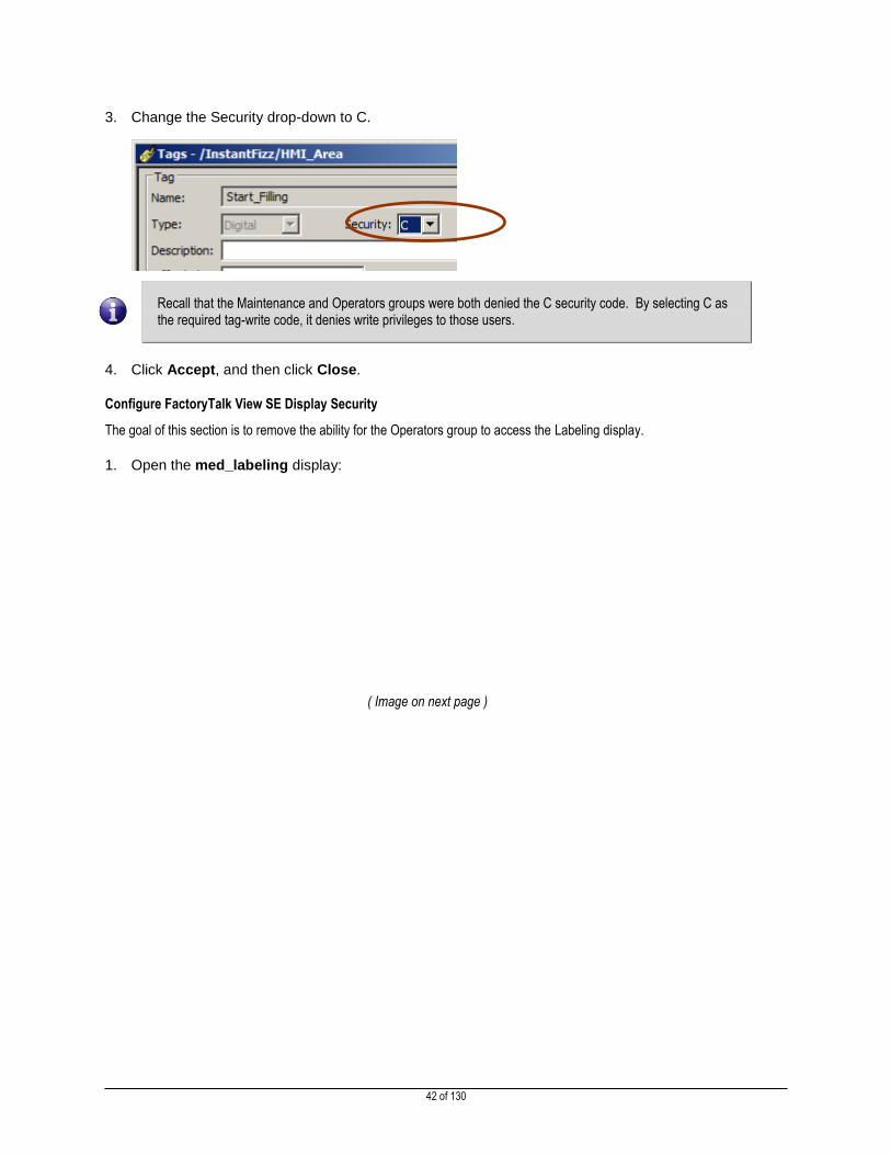
3. Change the Security drop-down to C.
Recall that the Maintenance and Operators groups were both denied the C security code. By selecting C as the required tag-write code, it denies write privileges to those users.
4. Click Accept, and then click Close.
Configure FactoryTalk View SE Display Security
The goal of this section is to remove the ability for the Operators group to access the Labeling display.
1. Open the med_labeling display:
( Image on next page )

43 of 130

44 of 130
2. Right-click on the background of the display (as opposed to one of the objects) and select Display
Settings…
3. The Security Code drop-down is currently set to the asterisk (*), meaning that any user with any
security code authorization can access this screen. Change the code to B.
Recall that the Operators group was denied the B security code. Requiring the B security code for access to this display means that the Operators will not be able to open it.
4. Click the OK button to apply this change and close the Display Security dialog.
5. Close the med_labeling display and click Yes to save the changes.

45 of 130
Configure FactoryTalk View SE Object Security
The goal of this section is to prevent the Operators group from having the ability to close the FactoryTalk View SE client from its
navigation bar.
1. Open the med_moremenu display:
46 of 130
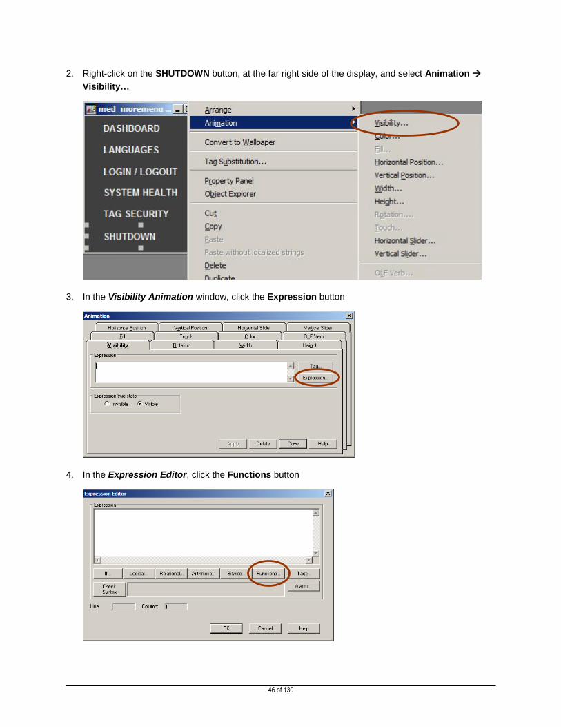
2. Right-click on the SHUTDOWN button, at the far right side of the display, and select Animation
Visibility…
3. In the Visibility Animation window, click the Expression button
4. In the Expression Editor, click the Functions button
47 of 130
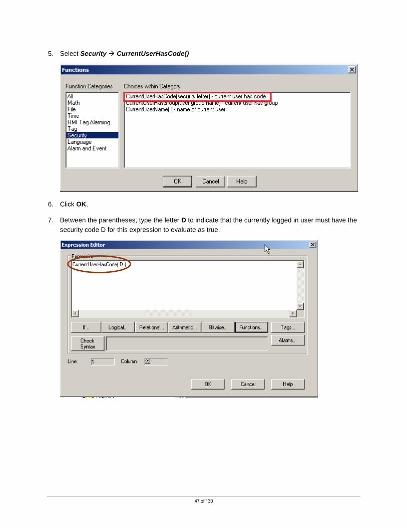
5. Select Security CurrentUserHasCode()
6. Click OK.
7. Between the parentheses, type the letter D to indicate that the currently logged in user must have the
security code D for this expression to evaluate as true.

48 of 130
8. Select Logical… OR
9. Click the Functions…. Button again
10. Select Security CurrentUserHasGroup( )
11. Click OK
49 of 130
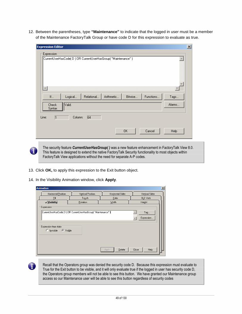
12. Between the parentheses, type “Maintenance” to indicate that the logged in user must be a member
of the Maintenance FactoryTalk Group or have code D for this expression to evaluate as true.
The security feature CurrentUserHasGroup( ) was a new feature enhancement in FactoryTalk View 8.0. This feature is designed to extend the native FactoryTalk Security functionality to most objects within FactoryTalk View applications without the need for separate A-P codes.
13. Click OK, to apply this expression to the Exit button object.
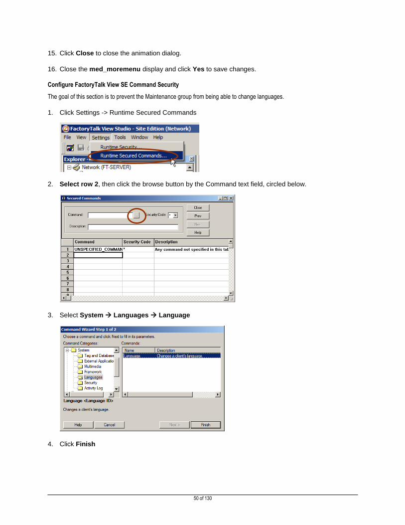
14. In the Visibility Animation window, click Apply.
Recall that the Operators group was denied the security code D. Because this expression must evaluate to True for the Exit button to be visible, and it will only evaluate true if the logged in user has security code D, the Operators group members will not be able to see this button. We have granted our Maintenance group access so our Maintenance user will be able to see this button regardless of security codes
50 of 130
15. Click Close to close the animation dialog.
16. Close the med_moremenu display and click Yes to save changes.
Configure FactoryTalk View SE Command Security
The goal of this section is to prevent the Maintenance group from being able to change languages.
1. Click Settings -> Runtime Secured Commands
2. Select row 2, then click the browse button by the Command text field, circled below.
3. Select System Languages Language
4. Click Finish

51 of 130
5. Select E from the Security Code drop-down menu.
Recall that the Maintenance group was denied the security code E, meaning that user will not be able to issue the Language command. This means that the Maintenance group members will be unable to change languages at runtime.
6. Click Accept to apply the changes.
7. Click Close, and then click Yes to save changes
8. Close FactoryTalk View Studio.
FactoryTalk View SE Security at Runtime
This demonstrates how secured components behave during runtime by navigating through the configured project with different
users. A brief walkthrough of the full project will be shown first such that a comparison may be made between the secured
behavior and the standard operation of the project. After this, different users will log in to exercise the secured components.
InstantFizz Application Normal Runtime
The goal of this section is to understand how the application runs with full security rights.
1. Launch the InstantFizz View SE Client application from the Desktop.

52 of 130
2. Log into the client as our supervisor (password: rockwell) and click OK.
3. When the client has finished loading, note that the supervisor user is currently logged in, granting full
rights to the application as a member of the Supervisors group.
Note that the Exit button is visible on the Navigation bar under More… – this button will not be visible to the Operators users when they log in.
4. Navigate to the Labeling screen by clicking the security key button on the navigation bar.
Recall that this screen has display level security requiring security code B for viewing. When the Operators group members log in, this screen will not display for them.
5. Navigate to the Filling screen now.
53 of 130
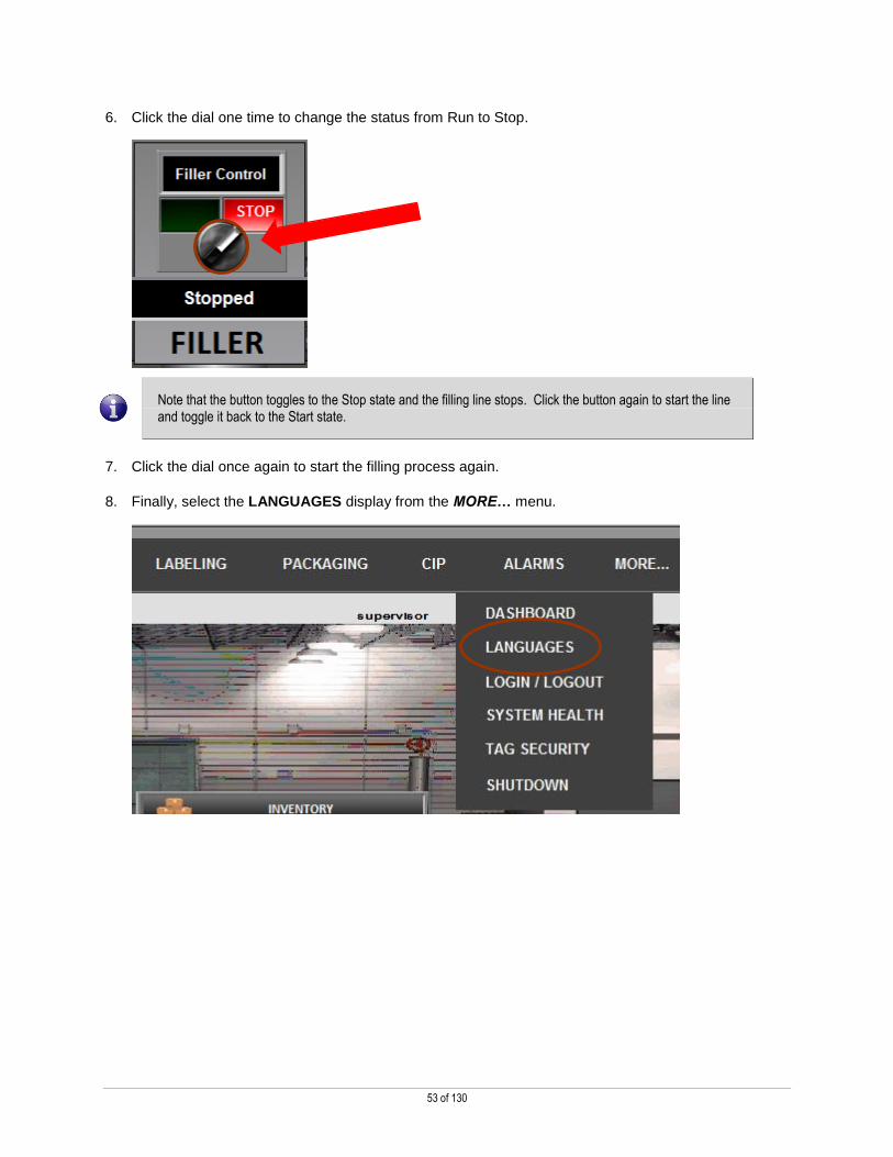
6. Click the dial one time to change the status from Run to Stop.
Note that the button toggles to the Stop state and the filling line stops. Click the button again to start the line and toggle it back to the Start state.
7. Click the dial once again to start the filling process again.
8. Finally, select the LANGUAGES display from the MORE… menu.

54 of 130
9. When the language selection screen appears, select Spanish. Note that the application’s language
switches.
Take note of the fact that the text fields in this display switched to Spanish.
10. Switch back to English (Inglés), then close the Language Switching display.
Exercise InstantFizz Security Configuration
The goal of this section is to log in as various users to observe how the security configuration effects the application at runtime.
1. Select the Login / Logout display from the MORE… menu
55 of 130
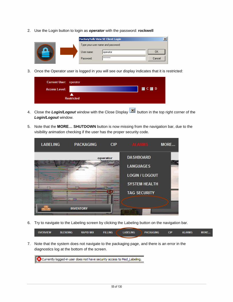
2. Use the Login button to login as operator with the password: rockwell
3. Once the Operator user is logged in you will see our display indicates that it is restricted:
4. Close the Login/Logout window with the Close Display button in the top right corner of the
Login/Logout window.
5. Note that the MORE… SHUTDOWN button is now missing from the navigation bar, due to the
visibility animation checking if the user has the proper security code.
6. Try to navigate to the Labeling screen by clicking the Labeling button on the navigation bar.
7. Note that the system does not navigate to the packaging page, and there is an error in the
diagnostics log at the bottom of the screen.

56 of 130
8. Now use the Login/Logout screen to log in as our Maintenance user, with the password: rockwell
9. Close the Login/Logout window with the Close Display button in the top right corner of the
Login/Logout window.
10. Notice the MORE… SHUTDOWN button reappears, as this user is a member of the allowed group
11. Navigate to the LABELING screen, which will display properly this time.
12. Navigate to the FILLING screen now.

57 of 130
13. Click the Start/Stop Button.
14. Note the error message displayed in the message window:
15. Push the LANGUAGES button from the MORE… menu on the navigation bar.
16. Attempt to change the language to Spanish, and note the error message displayed in the message
window:
17. Click the SHUTDOWN button from the MORE… menu on the navigation bar.
58 of 130
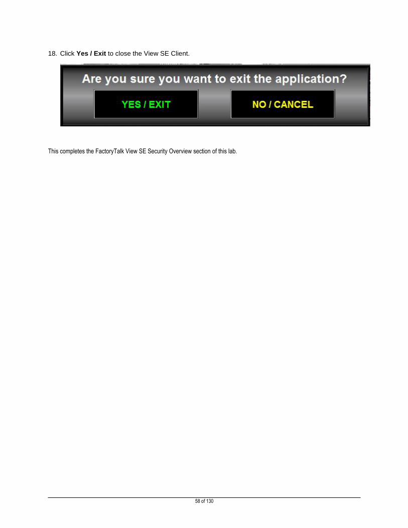
18. Click Yes / Exit to close the View SE Client.
This completes the FactoryTalk View SE Security Overview section of this lab.

59 of 130
Section 3: Securing Controller Data and Data Access
This section will explain how program data and data access control is configured to ensure that your data is protected from
design time all the way to implementation and runtime.
Data Access Control
In Logix Designer, v18 and greater, there are two tag attributes that allow you to control access to tag data:
External Access
Constant
The External Access attribute controls how external applications, such as HMIs, can access tags. It has possible values of
Read/Write, Read Only, and None.
The Constant attribute value determines if a tag can be modified by controller logic. Also, by using FactoryTalk Security software,
it is possible to control which users are permitted to change tags designated as constants in Logix Designer software.
By using these two attributes, you can help safeguard tag data by preventing unwanted changes to tag values. Also, by reducing
the number of tags exposed to external applications, you can also reduce the time required to develop HMI screens, and improve
the performance of data servers by reducing the total number of tags on scan.
For more information on Data Access Control see the Logix Designer Controllers I/O and Tag Data Programming Manual
(Publication 1756-PM004C-EN-P):
http://literature.rockwellautomation.com/idc/groups/literature/documents/pm/1756-pm004_-en-p.pdf
QR Code for Direct Link:
60 of 130
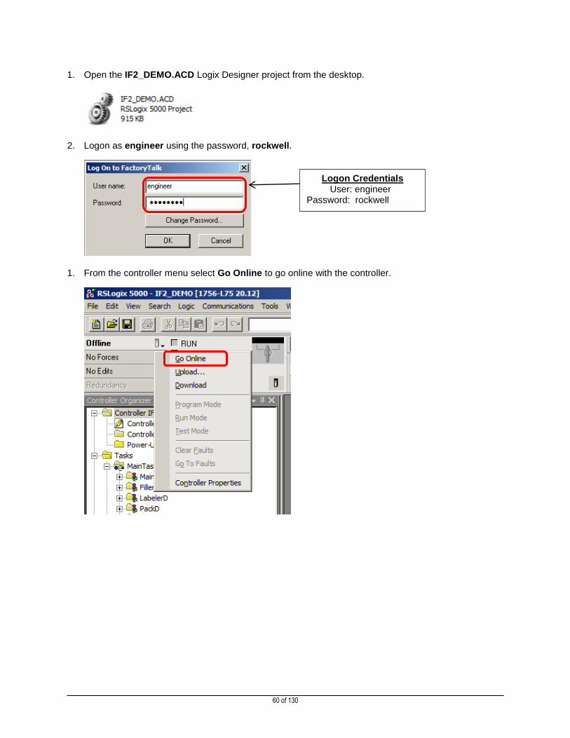
1. Open the IF2_DEMO.ACD Logix Designer project from the desktop.
2. Logon as engineer using the password, rockwell.
1. From the controller menu select Go Online to go online with the controller.
Logon Credentials User: engineer Password: rockwell

61 of 130
2. Be sure the controller is in the Run from the controller menu in Logix Designer.
frtad
3. Expand the Controller Organizer tree to Tasks SecurityDemo SecurityDemoProg
Program Tags is visible.
4. Double click on Program Tags

62 of 130
5. If not already selected, click the Edit Tags tab on the bottom of the window.
6. Scroll to the right until you can see the columns External Access and Constant.
The following subsections will explain the External Access & Constant functionality of Logix Designer and how these
enhancements to the Rockwell Automation Integrated Architecture system can be utlized to implement some stronger security
practices in applications.
63 of 130
External Access
About External Access
By using the External Access feature, you can control how external applications and devices access tags.
This feature also can improve system performance by reducing the number of tags the data server (RSLinx in our case) has to
maintain, scan, and cache. Lowering the work load on data servers can improve the performance of related applications such as
an HMI.
External applications and devices include:
Data Servers (In Rockwell Automation solutions these are RSLinx Classic and RSLinx Enterprise)
PC Based HMIs (In Rockwell Automation solutions these are FactoryTalk View Site Edition, Machine Edition Station)
Other controllers (Such as SLC, Micro, MicroLogix, PLC-5, or other vendors controllers)
Panel Based HMIs (In Rockwell Automation solutions these are PanelView and PanelView Plus HMIs)
Data Historians (In Rockwell Automation solutions this is FactoryTalk Historian)
Data Reporting (FactoryTalk VantagePoint, Transaction Manager, ProductionCentre, Metrics, AssetCentre, etc…)
Other third-party software.
For more information on External Access see the Logix Designer Controllers I/O and Tag Data Programming Manual
(Publication 1756-PM004C-EN-P), link and QR code at the beginning of this section.
Limiting External Access to Tags
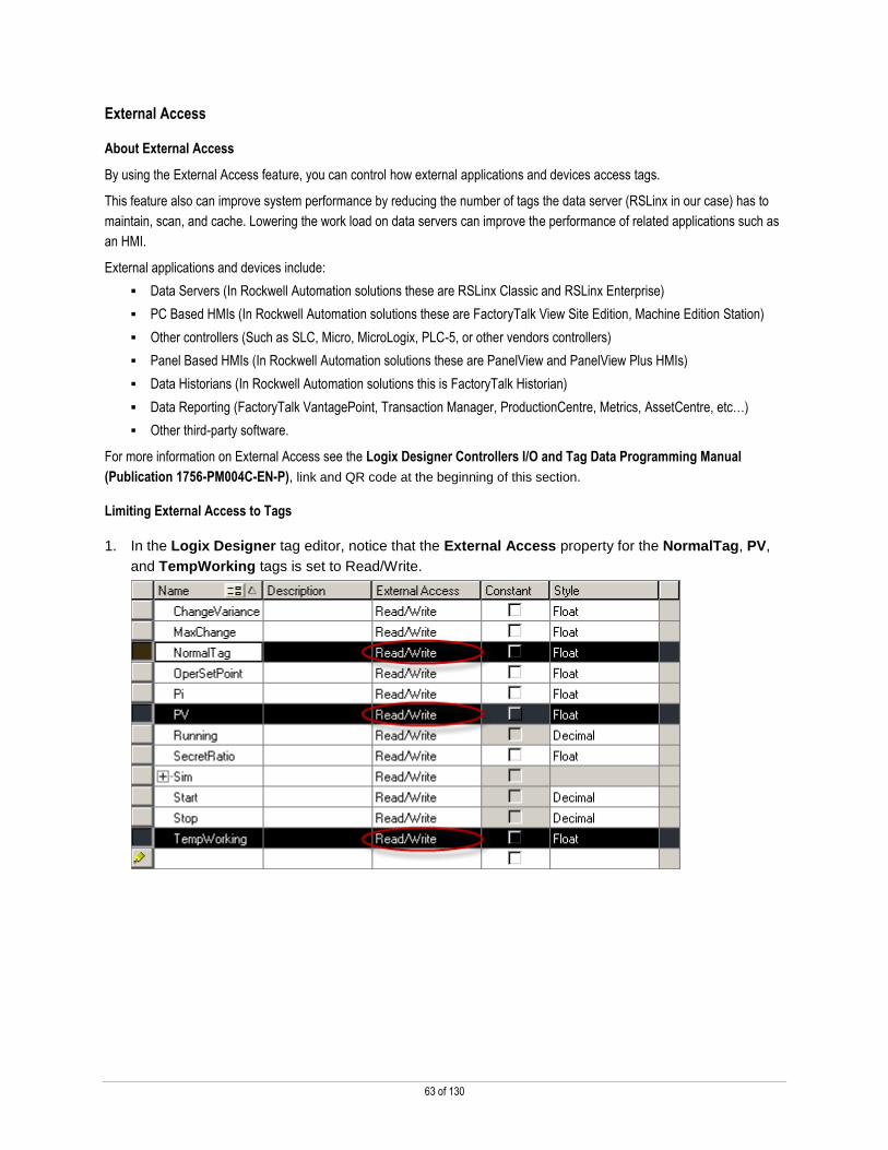
1. In the Logix Designer tag editor, notice that the External Access property for the NormalTag, PV,
and TempWorking tags is set to Read/Write.
64 of 130
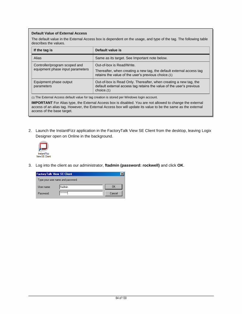
2. Launch the InstantFizz application in the FactoryTalk View SE Client from the desktop, leaving Logix
Designer open on Online in the background.
3. Log into the client as our administrator, ftadmin (password: rockwell) and click OK.
Default Value of External Access
The default value in the External Access box is dependent on the usage, and type of the tag. The following table describes the values.
If the tag is Default value is
Alias Same as its target. See Important note below.
Controller/program scoped and equipment phase input parameters
Out-of-box is Read/Write.
Thereafter, when creating a new tag, the default external access tag retains the value of the user’s previous choice.(1)
Equipment phase output parameters
Out-of-box is Read Only. Thereafter, when creating a new tag, the default external access tag retains the value of the user’s previous choice.(1)
(1) The External Access default value for tag creation is stored per Windows login account.
IMPORTANT For Alias type, the External Access box is disabled. You are not allowed to change the external
access of an alias tag. However, the External Access box will update its value to be the same as the external access of the base target.

65 of 130
4. When the client has finished loading, select the TAG SECURITY display from the MORE… menu.
5. Click on Numeric Entry labeled Normal Tag. Type a new value in and hit the Enter key. Watch the
value change in the numeric display to the right.
6. Repeat above step, writing a value to PV and then Temp Working Tag.
7. Switch back to Logix Designer, leaving the InstantFizz ViewSE client open.
Enter a new value here.
The value should change here.

66 of 130
8. Change the value of the External Access property for the tags listed below.
Tag External Access
NormalTag Read/Write
PV Read Only
TempWorking None
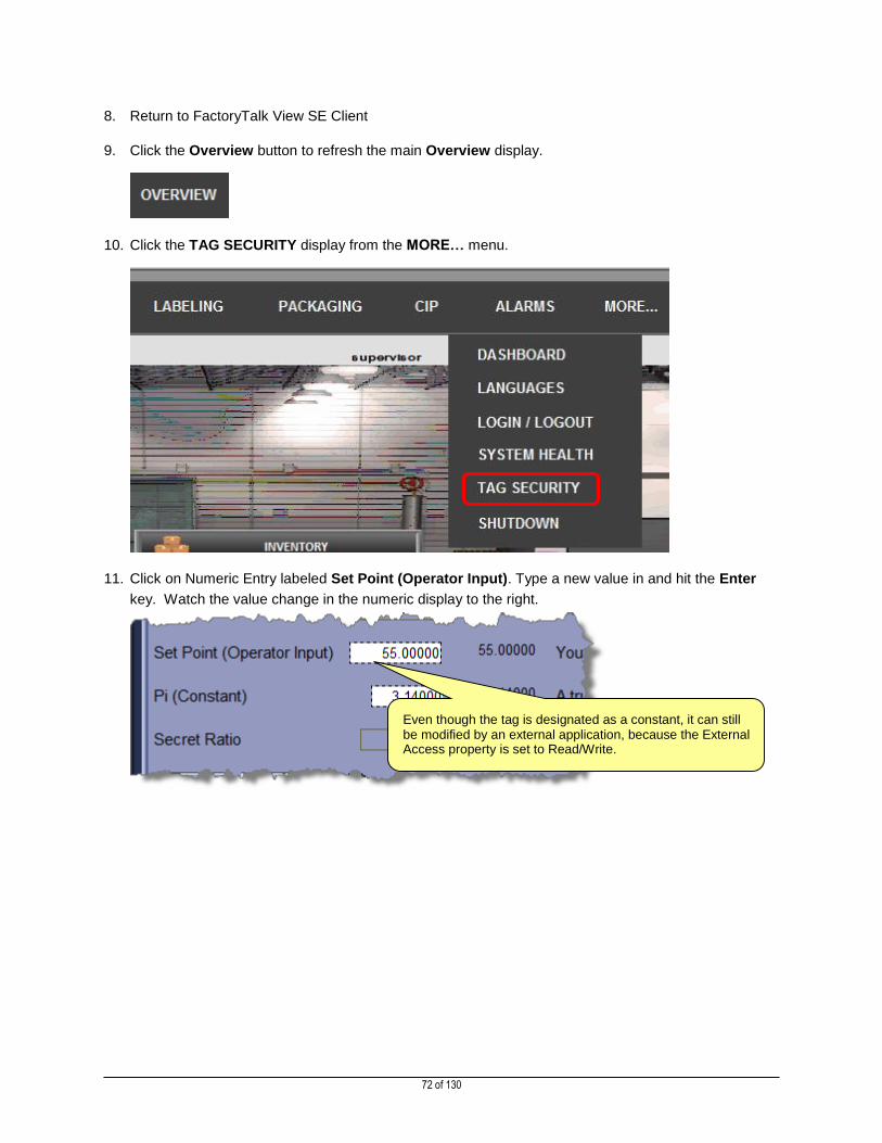
9. Return to FactoryTalk View SE Client
10. Click the Overview button to refresh the main Overview display.
11. Click the TAG SECURITY display from the MORE… menu.

67 of 130
12. Click on numeric entry labeled Normal Tag. Type a new value in and hit the Enter key. Watch the
value change in the numeric display to the right.
13. Click on numeric entry labeled PV. Type a new value in and hit the Enter key.
Notice that the value doesn’t change in the Numeric Display to the right, the input box turns red, and an error is logged to
the Diagnostics List.
Enter a new value here.
The value should change here.
An error is logged to FactoryTalk Diagnostics and is displayed in the Diagnostics List

68 of 130
14. Notice that the numeric input and numeric display objects that are labeled Temp Working are now
wire-framed.
This completes the External Access section of this lab. Leave both Logix Designer and the InstantFizz View SE Client Open and
proceed to the next section.
These values are “wire-framed” indicating that there is no data available for the specified tag. This is because the tag was specified as no external access in the controller.
69 of 130
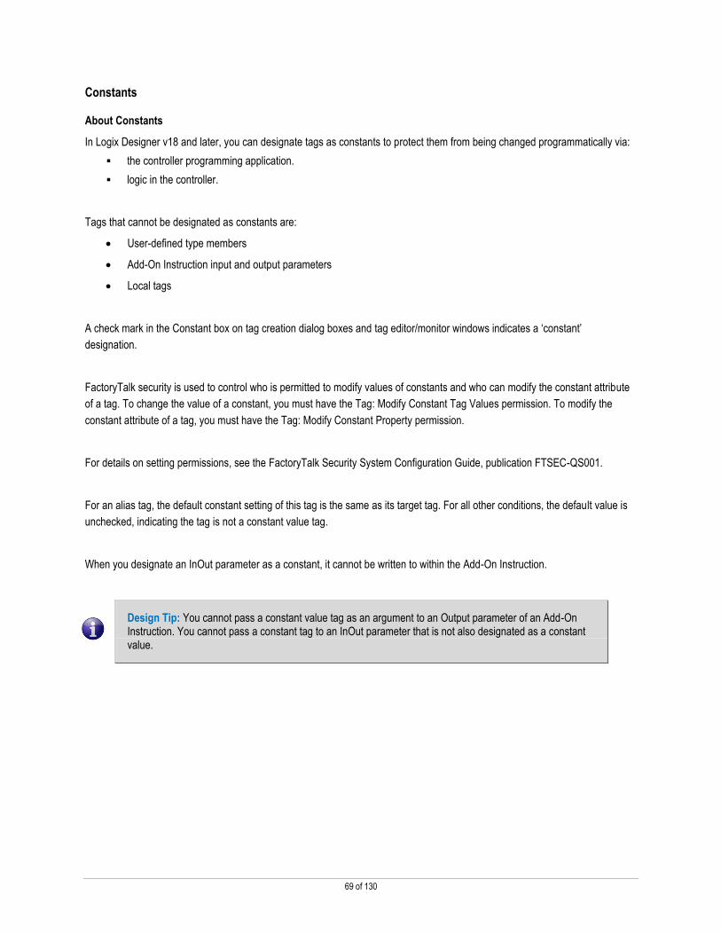
Constants
About Constants
In Logix Designer v18 and later, you can designate tags as constants to protect them from being changed programmatically via:
the controller programming application.
logic in the controller.
Tags that cannot be designated as constants are:
User-defined type members
Add-On Instruction input and output parameters
Local tags
A check mark in the Constant box on tag creation dialog boxes and tag editor/monitor windows indicates a ‘constant’
designation.
FactoryTalk security is used to control who is permitted to modify values of constants and who can modify the constant attribute
of a tag. To change the value of a constant, you must have the Tag: Modify Constant Tag Values permission. To modify the
constant attribute of a tag, you must have the Tag: Modify Constant Property permission.
For details on setting permissions, see the FactoryTalk Security System Configuration Guide, publication FTSEC-QS001.
For an alias tag, the default constant setting of this tag is the same as its target tag. For all other conditions, the default value is
unchecked, indicating the tag is not a constant value tag.
When you designate an InOut parameter as a constant, it cannot be written to within the Add-On Instruction.
Design Tip: You cannot pass a constant value tag as an argument to an Output parameter of an Add-On Instruction. You cannot pass a constant tag to an InOut parameter that is not also designated as a constant value.

70 of 130
Protecting Tags from Programmatic Modification
1. Return to Logix Designer. Notice the values of the External Access and Constant properties for the
OperSetPoint, Pi, and SecretRatio. External Access should be set to Read/Write, and the Constant
property should be unchecked for all 3 tags.
2. Return to the InstantFizz View SE Client’s Tag Based Security Demo display.
3. Click on Numeric Entry labeled Set Point (Operator Input). Type a new value in and hit the Enter
key. Watch the value change in the numeric display to the right.
4. Click on Numeric Entry labeled Pi (Constant). Type the value 3.14 in and hit the Enter key. Watch
the value change in the numeric display to the right.
5. Click on Numeric Entry labeled Secret Ratio. Type the value .0218 in and hit the Enter key. Watch
the value change in the numeric display to the right.
Notice the Constant property is unchecked.

71 of 130
6. Return to Logix Designer.
7. Change the value of the External Access property and Constant property for the tags listed below.
Tag External Access Constant
OperSetPoint Read/Write
Pi Read Only
SecretRatio None
72 of 130
8. Return to FactoryTalk View SE Client
9. Click the Overview button to refresh the main Overview display.
10. Click the TAG SECURITY display from the MORE… menu.
11. Click on Numeric Entry labeled Set Point (Operator Input). Type a new value in and hit the Enter
key. Watch the value change in the numeric display to the right.
Even though the tag is designated as a constant, it can still be modified by an external application, because the External Access property is set to Read/Write.

73 of 130
12. Click on Numeric Entry labeled Pi (Constant). Type a new value in and hit the Enter key. Notice that
the value doesn’t change in the Numeric Display to the right and an error is logged to the Diagnostics
List.
13. Notice that the Numeric Input and Numeric Display objects that are labeled Secret Ratio are now
wire-framed.
14. Click the SHUTDOWN button from the MORE… menu on the navigation bar.
15. Click Yes / Exit to close the View SE Client.
Red indicates there was an error writing the value to the controller.
The value doesn’t change because it was never written to the controller.
An error is logged to FactoryTalk Diagnostics and is displayed in the Diagnostics List
These values are “wire-framed” indicating that there is no data available for the specified tag. This is because the External Access property for this tag was specified as None in the controller.

74 of 130
16. Return to Logix Designer.
17. Double click on MainRoutine in SecurityDemoProg to open the Ladder Logic
18. Click on rung 0 and then click on the new rung button.
Double-click to open the ladder logic editor.
Click on the Rung button on the toolbar.

75 of 130
19. Use the scroll button ( ) in the instructions toolbar to scroll until you can see the Move/Logical tab.
Click on the Move/Logical tab.
20. Click the MOV button on the instruction toolbar to add a new MOV instruction to the rung.
Set the source to NormalTag and the destination as OperSetPoint.
21. Click the Accept Pending Rung Edits button on the toolbar.
Use the scroll button to scroll to the Move/Logical tab.
The blue circle with horizontal white line icon ( ) indicates that the selected tag is a constant.
The blue “e” indicates there is an error on the rung. This is because the MOV instruction is trying to use a constant as a destination
Click the Accept Pending Rung Edits button.

76 of 130
22. Notice that Logix Designer reports that there is an error with the new rung. This is because a tag that
has been designated as a constant cannot be the destination for any instruction.
23. Try again using Pi and/or SecretRatio
24. Undo changes
25. Click Yes, when prompted to cancel edits.

77 of 130
26. Click the save button ( ) on the toolbar to save the program, answer Yes to when prompted to
upload data.
Protecting Tags from User Modification
In addition to protecting tags from programmatic modification, you can also limit who has permission to edit constant values
using Logix Designer.
1. From the Logix Designer tool menu select Tools Security Log On
2. When prompted to login we will now login as our maintenance user, maintenance with the password,
rockwell.
3. Open the Program Tags from Tasks SecurityDemo Program Tags
4. Click on the Monitor Tags tab.
Logon Credentials User: maintenance Password: rockwell

78 of 130
5. Change the value of SecretRatio to another number.
6. Launch the FactoryTalk Administration Console from the Desktop if not already open.
7. Select the Network directory option when prompted and click OK
8. When prompted to login, login using the following administrative credentials.
Select Network in the FactoryTalk
Directory Window and click OK.
Logon Credentials User: ftadmin
Password: rockwell

79 of 130
9. Right click on Network (FTSEC-DEMO14) in the Explorer tree. Choose Security…
10. In the Security Settings, select the Maintenance group in the top pane. Then scroll down to and
expand the RSLogix5000 group.

80 of 130
11. Scroll down in the permissions list until you see Tag: Modify Constant Property and Tag: Modify
Constant Tag Values under the RSLogix5000 group.
12. Uncheck the Tag: Modify Constant Property and Tag: Modify Constant Tag Values under the
Logix Designer group.
13. Click OK.
14. Close the FactoryTalk Administration Console.
15. Return to Logix Designer.
16. From the Logix Designer, select Tools Security Refresh Privileges
17. Notice that Value field is greyed out for all of the constant tags.
Note: If the fields do not become non-editable you may not have enabled security from section 1 of this lab.

81 of 130
18. Select Tools Security Log On
19. Login as engineer (password: rockwell)
20. Open the Tag Monitor from the SecurityDemo Program Tags window
21. Change the value of SecretRatio to 0.025
22. Close Logix Designer and save changes, uploading tag values, when prompted.
This completes the Securing Controller Data section of the lab.
Logon Credentials User: engineer Password: rockwell
82 of 130
Section 4: Protecting Logix Designer Source Code
This section will take approximately 20 minutes to complete.
Source protection is useful to protect the intellectual property or critical areas of an Logix Designer application from unauthorized
access. You can restrict access to the following type of Logix 5000 objects:
Add-On Instructions
Routines
o Ladder
o Function Block Diagrams
o Sequential Function Charts
o Structured Text
About Logix Designer Source Protection
The Logix Designer Source Protection feature allows you to protect your routines and Add-On Instructions (AOIs) using a source
key file. Using this key file, you can open your Logix Designer project files with full access to read and write every aspect of the
project. If the key file is removed from the system then the routines selected in the project are secured based on the desired
configuration within the Source Protection configuration.
For more information about Logix Designer Source Protection please refer to the FactoryTalk Security System Configuration
Guide (FTSEC-QS001-EN-E) from the Rockwell Automation Literature Library, direct link & QR code below.
http://literature.rockwellautomation.com/idc/groups/literature/documents/qs/ftsec-qs001_-en-e.pdf

83 of 130
Configuring Source Protection on a Logix Designer Application File
After enabling the Source Protection function via the Logix Designer installation the Configure Source Protection is available from
the Tools > Security menu. For the purposes of this lab, the Source Protection Tool has already been enabled. This utility is an
optional component of the installation made available by checking the box during the installation labelled “Enable Source
Protection”.
1. Open the IF2_DEMO.ACD project in Logix Designer.
2. Logon as engineer using the password, rockwell. If the application is already open select Log On…
from the Tools Security menu of Logix Designer to login as the engineer.
3. Select Configure Source Protection from the Tools > Security menu.
Design Tip: Source Protection can only be configured on an offline project file.
4. Source Protection requires a Source Key File location to be specified. Click Yes to specify the Source
Key File location.
Logon Credentials User: engineer Password: rockwell

84 of 130
5. The following dialog will open, enter this path: C:\Lab Files\ into the Source Key File Location: field
and click OK to create the sk.dat key file in this location.
6. Acknowledge the warning about creating the file in this location.
Design Tip: You may want to store this key file in a secured area of FactoryTalk AssetCentre, but it would have to be downloaded separately to be accessed. Logix Designer cannot access a key file inside the FactoryTalk AssetCentre archive.

85 of 130
7. View the Source Protection Configuration options:
When the Source Protection Configuration dialog box displays, you will see all of the Program routines and Add-On
Instructions in the project file:
8. Highlight the PFlex_700_AOI routine, and click the Protect button.

86 of 130
9. Enter VendorCode as the source key. Show Source Key can be enabled to see the value in
plaintext. Click OK to continue.
Design Tip: An ideal key uses all characters available on the keyboard including letters, punctuation, symbols, and numbers. The greater the variety of characters used, the better.
10. The PFlex_700_AOI routine is now protected with the key VendorCode.
87 of 130
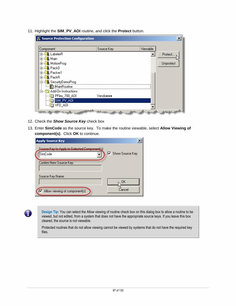
11. Highlight the SIM_PV_AOI routine, and click the Protect button.
12. Check the Show Source Key check box
13. Enter SimCode as the source key. To make the routine viewable, select Allow Viewing of
component(s). Click OK to continue.
Design Tip: You can select the Allow viewing of routine check box on this dialog box to allow a routine to be viewed, but not edited, from a system that does not have the appropriate source keys. If you leave this box cleared, the source is not viewable.
Protected routines that do not allow viewing cannot be viewed by systems that do not have the required key files.

88 of 130
14. The SIM_PV_AOI routine is protected, but can be viewed in a read only mode by sources that do not
have the key file.
15. Highlight the VFD_AOI routine, and click the Protect button.

89 of 130
16. Check the Show Source Key check box.
17. Enter ProtectedCode as the source key. Click OK to continue.
18. The VFD_AOI routine is protected, and cannot be viewed by sources that do not have the key file.

90 of 130
19. Highlight the SecurityDemoProg MainRoutine routine, and click the Protect button.
20. Select the ProtectedCode as the source key from the drop down. To make the routine viewable,
select Allow Viewing of component(s). Click OK to continue.
21. The MainRoutine routine is protected, but can be viewed in a read only mode by sources that do not
have the key file.
Design Tip: Notice that the same Source Key can be used for multiple routines. You can also make some routines visible using the same source key as other routines are not visible.
91 of 130
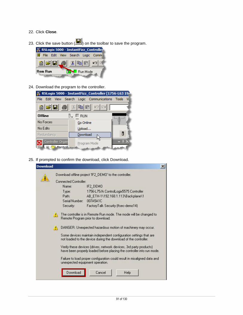
22. Click Close.
23. Click the save button ( ) on the toolbar to save the program.
24. Download the program to the controller.
25. If prompted to confirm the download, click Download.

92 of 130
26. When prompted to return the controller back to Remote Run, click Yes.
WARNING: If you export a source-protected Add-On Instruction and want the exported contents encrypted, you must first remove, rename, or move the source key file (sk.dat). This causes the exported Add-On Instructions to be encrypted.
Viewing and editing protected routines
When the project file is downloaded or opened on a system that does not contain the keys used to secure the project file, the
routines and Add-On Instructions will be protected based on the Source Protection Configuration.
1. Close Logix Designer, saving changes if prompted.
2. From the Desktop open the folder called Lab Files
3. Move, do not copy, the sk.dat file from the Lab Files folder to the Desktop.
Recall this is our key file that we secured several object with in Logix Designer. Removing this file
from the configured location should secure those objects as we configured.
4. Open Logix Designer once again
5. Logon as engineer using the password, rockwell.
Logon Credentials User: engineer Password: rockwell

93 of 130
6. Navigate to the SecurityDemo task and open the Main Routine.
7. Next, navigate to the VFD_AOI Add-On Instruction and open it.
MainRoutine was protected and set to viewable. The routine can be opened as read only on a system that does not contain the key for the routine; the user cannot modify the routine.
VFD_AOI was protected and not viewable. The tag and code within the AOI are not viewable on a system that does not contain the key for the routine; the user cannot modify the routine.
Even though the VFD_AOI was protected and not viewable, users can still see the definition information. This information may be necessary to actually make use of the AOI.
The user cannot modify the definition.
94 of 130
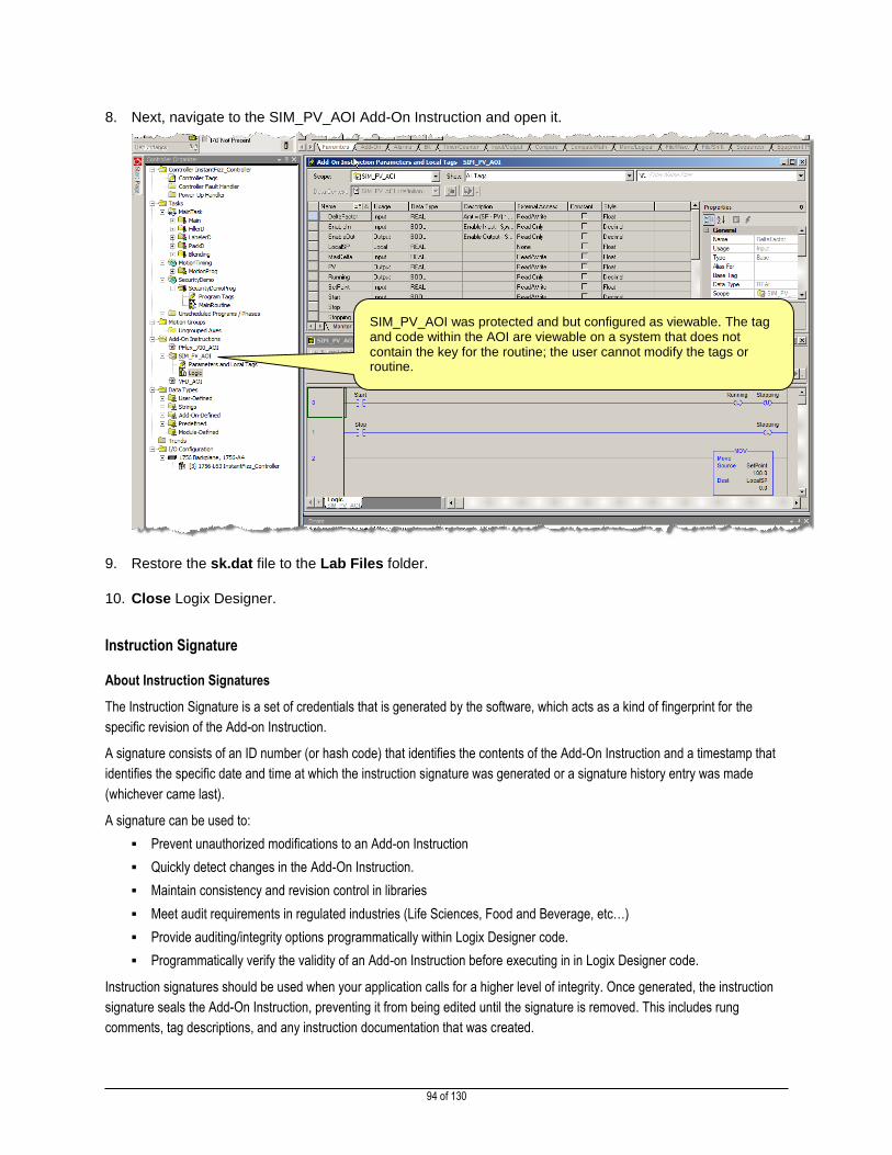
8. Next, navigate to the SIM_PV_AOI Add-On Instruction and open it.
9. Restore the sk.dat file to the Lab Files folder.
10. Close Logix Designer.
Instruction Signature
About Instruction Signatures
The Instruction Signature is a set of credentials that is generated by the software, which acts as a kind of fingerprint for the
specific revision of the Add-on Instruction.
A signature consists of an ID number (or hash code) that identifies the contents of the Add-On Instruction and a timestamp that
identifies the specific date and time at which the instruction signature was generated or a signature history entry was made
(whichever came last).
A signature can be used to:
Prevent unauthorized modifications to an Add-on Instruction
Quickly detect changes in the Add-On Instruction.
Maintain consistency and revision control in libraries
Meet audit requirements in regulated industries (Life Sciences, Food and Beverage, etc…)
Provide auditing/integrity options programmatically within Logix Designer code.
Programmatically verify the validity of an Add-on Instruction before executing in in Logix Designer code.
Instruction signatures should be used when your application calls for a higher level of integrity. Once generated, the instruction
signature seals the Add-On Instruction, preventing it from being edited until the signature is removed. This includes rung
comments, tag descriptions, and any instruction documentation that was created.
SIM_PV_AOI was protected and but configured as viewable. The tag and code within the AOI are viewable on a system that does not contain the key for the routine; the user cannot modify the tags or routine.

95 of 130
When an instruction is sealed, you can perform only these actions:
Copy the instruction signature
Create or copy a signature history entry
Create instances of the Add-On Instruction
Download the instruction
Remove the instruction signature
Print reports
Copy the Add-on Instruction Definition to another project (the instruction will remain sealed and under source protection
if applicable)
Design Tip: If desired, source protection must be applied prior to generating an instruction signature. You will need the source key to create a signature history entry. When source protection is enabled, you can still copy the instruction signature or signature history, if they exist, but you cannot remove the signature, nor edit the AOI definition without the proper key.
Add-on Instructions that have a signature are often referred to as a High Integrity Add-On Instruction or Sealed Add-On
Instruction.
Generating a Signature
Follow these steps to generate an instruction signature:
1. Open Logix Designer once again logon as our engineering user, engineer.
2. Logon as engineer using the password, rockwell.
Logon Credentials User: engineer Password: rockwell

96 of 130
3. Double click on the VFD_AOI add-on instruction
Design Tip: You must be offline to perform this procedure. If this is a safety Add-On Instruction, the project cannot be safety-locked or have a safety task signature.
4. Click on the Signature tab.
5. Click the Generate button
97 of 130
6. Answer Yes to the prompt "Generate instruction signature?"
Re
This seals the instruction, generates its signature, updates the Last Edit Date, and places the instruction in a read-only state
to prevent edits.
Design Note: If unsaved edits exist on other tabs of the Add-On Instruction dialog box, the prompt reads as follows: "Unapplied edits exist in the add-on instruction. Do you want to apply edits and generate signature?" Answering Yes saves those edits and generates a signature.
Create a Signature History Entry
The signature history provides a record of signatures for future reference. A signature history entry consists of the name of the
user, the instruction signature, the timestamp value, and a user-defined description. You can only create a signature history if an
instruction signature exists and you are offline. Creating a signature history changes the Last Edited Date, which becomes the
timestamp shown in the history entry. Up to six history entries may be stored.
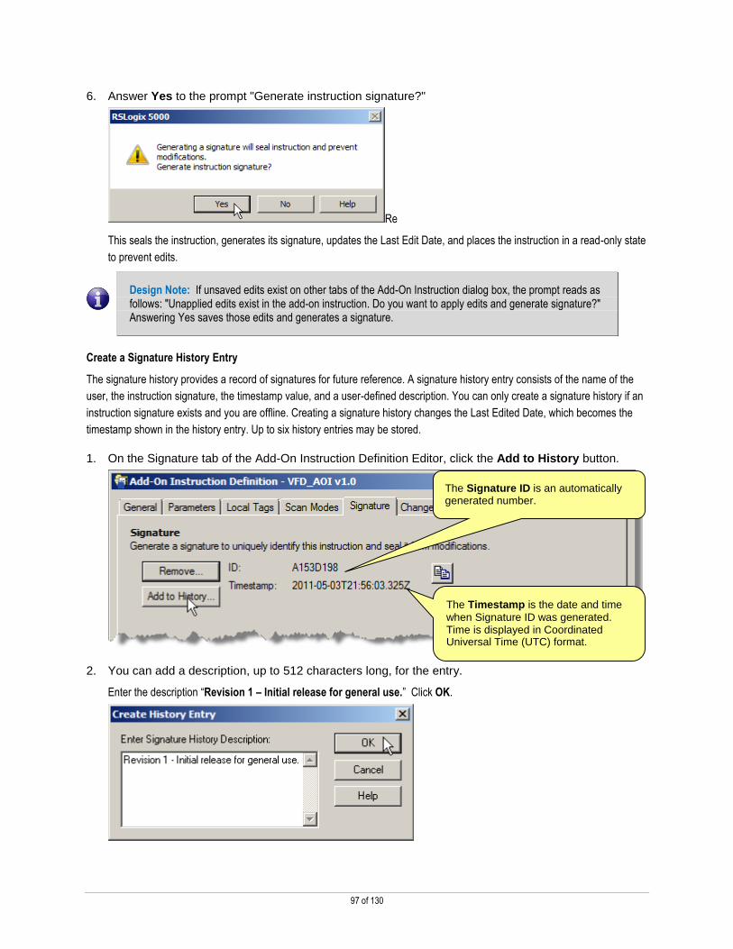
1. On the Signature tab of the Add-On Instruction Definition Editor, click the Add to History button.
2. You can add a description, up to 512 characters long, for the entry.
Enter the description “Revision 1 – Initial release for general use.” Click OK.
The Signature ID is an automatically generated number.
The Timestamp is the date and time
when Signature ID was generated. Time is displayed in Coordinated Universal Time (UTC) format.
98 of 130
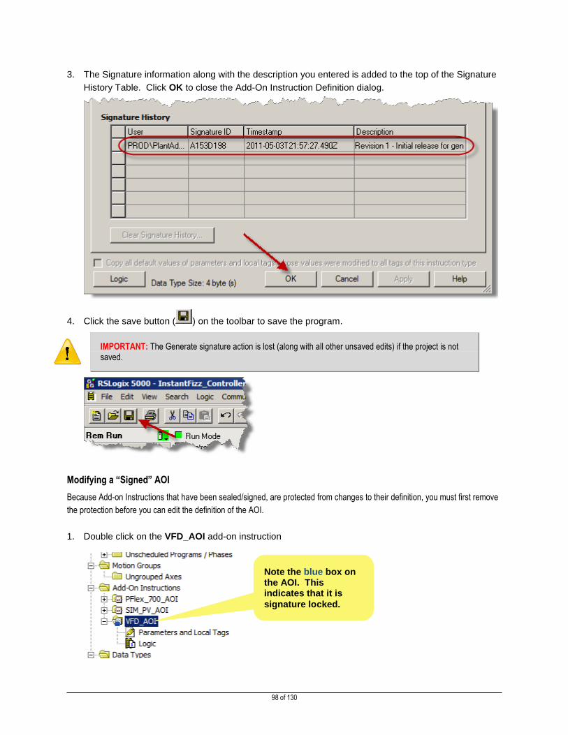
3. The Signature information along with the description you entered is added to the top of the Signature
History Table. Click OK to close the Add-On Instruction Definition dialog.
4. Click the save button ( ) on the toolbar to save the program.
IMPORTANT: The Generate signature action is lost (along with all other unsaved edits) if the project is not saved.
Modifying a “Signed” AOI
Because Add-on Instructions that have been sealed/signed, are protected from changes to their definition, you must first remove
the protection before you can edit the definition of the AOI.
1. Double click on the VFD_AOI add-on instruction
Note the blue box on the AOI. This indicates that it is
signature locked.

99 of 130
2. Click on the Signature tab.
3. On the Signature tab of the Add-On Instruction Definition Editor, click the Remove button.
This will “unseal” the AOI so it can be modified.
4. Click Yes when prompted to Remove Signature..
5. Click OK to close the Add-On Instruction Definition dialog.
6. The AOI has been unsealed and can now be edited.

100 of 130
Getting Signature Information in Code
There is a new class in for the GSV instructions that allows you to get key AOI information programmatically. The following
information can be read using the new class name:
Element Description Data Type
Description
Class Name AddOnInstructionDefinition
Instance Name AOI Definition Name
Attribute Name MajorRevision DINT Major revision number of the Add-On Instruction
MinorRevision DINT Minor revision number of the Add-On Instruction
Name String Name of the Add-On Instruction RevisionExtendedText String Text describing the revision of the Add-On
Instruction Vendor String Vendor that created the Add-On
Instruction LastEditDate LINT Date and time stamp of the last edit to an
Add-On Instruction SignatureID DINT 32-bit instruction signature value SafetySignatureID DINT 32-bit safety instruction signature value
1. Double click on the Logic icon under VFD_AOI
2. Click on rung 0 and type GSV. Hit the Enter key.

101 of 130
3. Use the values below for the new GSV instruction. You will have to type SignatureID into the Dest
field, because the tag does not exist yet.
4. Right click on SignatureID in the Dest field and select New Local Tag ‘SignatureID’… from the
context menu.
5. In the New Tag dialog box, set the Usage to Output Parameter, and then click OK.

102 of 130
6. Double click on the VFD_AOI add-on instruction
7. On the General tab of the AOI Definition dialog, bump the Minor revision number up by one.
8. Click on the Signature tab.
9. Click the Generate button

103 of 130
10. You may be prompted to apply unsaved edits, click Yes to commit these changes.
11. If prompted with a warning about signatures, answer Yes to the prompt "Generate instruction
signature?"
12. On the Signature tab of the Add-On Instruction Definition Editor, click the Add to History button.
13. Enter the description “Revision 1.1 – Added SignatureID as an output parameter.” Click OK.

104 of 130
14. The Signature information along with the description you entered is added to the top of the Signature
History Table. Click OK to close the Add-On Instruction Definition dialog.
15. Click the save button ( ) on the toolbar to save the program.
IMPORTANT: The Generate signature action is lost (along with all other unsaved edits) if the project is not saved.
Distributing/Reusing a Protected/Signed AOI
1. Minimize ( ) the current Logix Designer program, DO NOT close it.
2. Launch a new instance of Logix Designer from the desktop.

105 of 130
3. Select Create New Project
4. Select the 1756-L75 ControlLogix® 5570 Controller
5. Enter the project name Test
6. Click Next

106 of 130
7. Under the Security Authority: field select FactoryTalk Security (FTSEC-DEMO14)
8. Click Finish
9. Logon as engineer using the password, rockwell.
10. Return to the IF2_DEMO project.
Logon Credentials User: engineer Password: rockwell
107 of 130
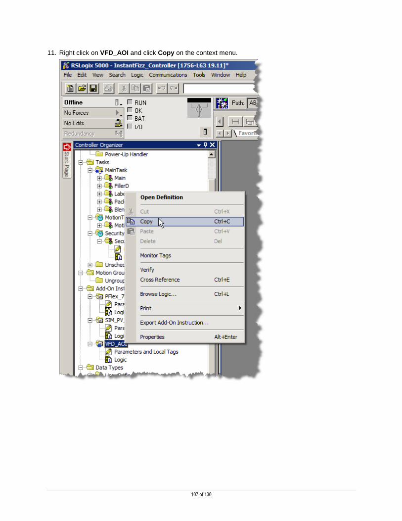
11. Right click on VFD_AOI and click Copy on the context menu.
108 of 130
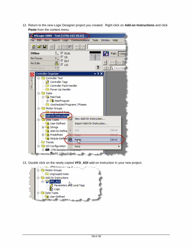
12. Return to the new Logix Designer project you created. Right click on Add-on Instructions and click
Paste from the context menu.
13. Double click on the newly copied VFD_AOI add-on instruction in your new project.

109 of 130
14. Click on the Signature tab.
15. Notice the remained intact through the copy/paste activity.
16. Close both Logix Designer applications. There is no need to save the changes to the new project.
This completes Protecting Logix Designer Source Code section of this lab.

110 of 130
Section 5: Change Management for ControlLogix Programmable Automation Controllers
This section of the lab outlines how to leverage security features within the Logix Designer to enhance the security of your
application and system.
This section will take approximately 20 minutes to complete.
After completing this section you should:
Understand how to use the new Change Detection features in Logix Designer (v20 & greater) & FactoryTalk
AssetCentre (v4.10 & greater).
ControlLogix Change Detection
Change detection is a new feature of Logix Designer, introduced in version 20.00 that allows users to track changes made to
Controllers via a controller log file and also synchronize those changes as audit messages directly the Audit Log of FactoryTalk
AssetCentre.
We are first going to explore the change detection functions in Logix Designer and investigate how to configure what types of
changes are tracked. Then we will move over to FactoryTalk AssetCentre where our maintenance user can review the audit log
for changes, and generate a report of changes made during a shift period.
Logix Designer Change Detection Configuration
1. Open Logix Designer once again logon as our engineer user (password: rockwell).
2. Logon as engineer using the password, rockwell.
3. Open the controller properties dialog, by pushing the button on the menu bar.
Logon Credentials User: engineer Password: rockwell

111 of 130
4. Once the Controller Properties dialog is open select the Security tab. You should see the window
shown below:
Note: Notice the Changes to Detect field circled in blue above. You will see this value displays all “F”’s. This hexadecimal key code is the mechanism that Logix Designer uses to calculate audit changes.
5. Click the Configure… button. You will see the list of all the items that can be audited in the
controller, but default all items are selected.
6. Uncheck the Remote mode change check box, shown below:
7. Click OK to close the Configure Changes to Detect dialog.

112 of 130
8. Notice how the Changes to Detect value has changed:
9. Click OK to close the Controller Properties window.
10. From the controller menu, select Download to download the project with these changes to the
controller.

113 of 130
11. From the download dialog click the Download button.
12. If the controller is not currently in run mode, switch the controller back to Run and stay Online.
13. Open the Controller Properties once again, by clicking the button, select the Security tab, and
notice how the Audit Value of the Change Detection field is populated and has a unique value. This
value is called the CCUID.
Note: Your value will likely not be the same as the one above, this value is unique.
14. Using the key on the controller change the mode of the processor to from REM to PROG, then PROG
to RUN, then finally back to REM.

114 of 130
15. Look at the Audit value again, notice that it changes from what you noted before.
This is an indication that a change has occurred on the system which has been capured in the
controllers change log.
16. Recalling that we disabled the change detect option for Remote Mode Changes from the Change
Detection configuration, change the processor mode from Run Mode to Program Mode. You will be
prompted with the dialog shown below warning about the change to program mode, click Yes to
acknowledge this warning.
17. Look at the Audit value again, notice that the value did not change from what you last.
Since this change is not tracked it will therefore not be retained as an audit value.
18. Click OK to close the Controller Properties dialog box.
19. Change the mode of the processor back to Run Mode from the Controller Menu.
The change detection feature in Logix Designer monitors all changes to the controller. While online with the controller feel free to
add additional tasks, Add-On Instructions, Data Types, etc… and take note of how the Audit Value in the controller property
dialog changes.

115 of 130
FactoryTalk AssetCentre Audit Logging
1. Leaving Logix Designer open, launch the FactoryTalk AssetCentre Client by double-clicking on the
icon that looks like the one below from the desktop.
2. When prompted to login we will now login as our maintenance user, maintenance with the password,
rockwell.
3. Once the client opens, from the menu along the top of the client interface click the Logs button
4. Once inside of the Logs module, select the audit messages by clicking on the button that says,
Audit Logs.
5. You should see several new audit log messages that look similar to the snippet below:
Note: Make special notice of the Source collecting these logs are Logix Designer. Also notice that the Resource name is the project name running on this particular controller, IF2_DEMO in our case. You will also note that since the engineer was logged into Logix Designer at the time these changes were made, the engineer was listed as the user making the change. This drastically simplifies the reporting process for controller change reports.
Logon Credentials User: maintenance Password: rockwell

116 of 130
FactoryTalk AssetCentre Audit Log Reporting
FactoryTalk AssetCentre has a large array of reporting options available. You can produce reports on file access from the
FactoryTalk AssetCentre Archive, event data from the FactoryTalk AssetCentre Event Log, network health reports from the
FactoryTalk AssetCentre Network Health Log using RSNetworx, and audit reports using the FactoryTalk AssetCentre audit log.
We are going to focus on the last area, the audit logs.
1. Click the button in the FactoryTalk AssetCentre client.
2. You will see several pre-configured searches that were already created in the list, we want to create
new one to look at changes in Logix Designer made today.
3. From the searches screen click the button
4. In the name field enter, Logix Designer Changes Today
5. In the lower field select the Audits Data Source and click Finished

117 of 130
6. Now that the search is created we need a add conditions to the search, in the lower field of the
search display click the Conditions tab.
7. Click the button
8. From the New Condition dialog select the Relative to date/time report is run radial button
9. Click OK to apply the condition.
10. Click the button again
Occurred Time means that we want to look at when the audit occurred, vs. when it was logged.
The default of 0 days ago, means we only want to look at Today.

118 of 130
11. From the Column field select Source.
12. From the lower String Condition field select Equal To and select Logix Designer from the list.
13. Click OK to apply this condition.
14. Notice in our condition list the second condition was added with an ‘AND’. This is the default
condition. You could also add this as an OR, or a NOT, but we want AND in our case.
15. Click the button in the lower right corner of the screen.
16. Click the button from the upper part of the Searches dialog and see next page.
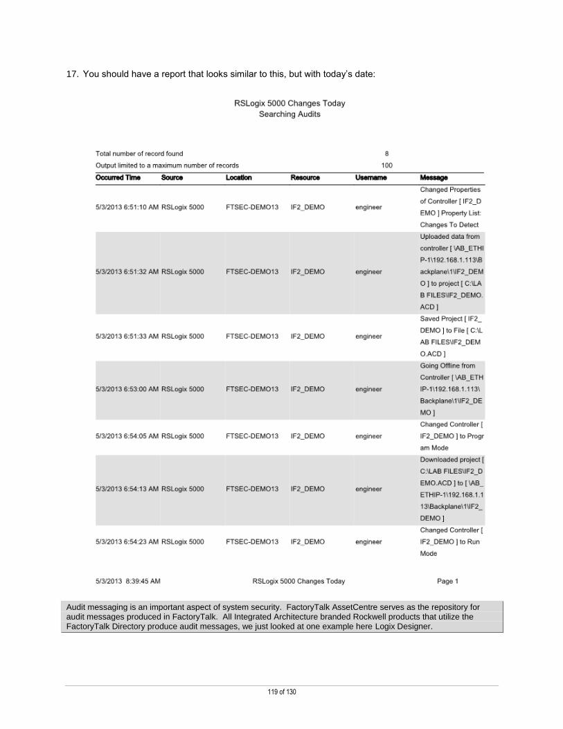
119 of 130
17. You should have a report that looks similar to this, but with today’s date:
Audit messaging is an important aspect of system security. FactoryTalk AssetCentre serves as the repository for audit messages produced in FactoryTalk. All Integrated Architecture branded Rockwell products that utilize the FactoryTalk Directory produce audit messages, we just looked at one example here Logix Designer.
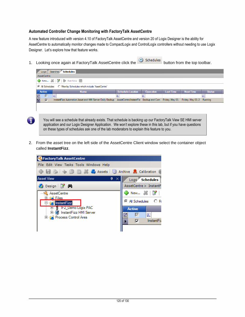
120 of 130
Automated Controller Change Monitoring with FactoryTalk AssetCentre
A new feature introduced with version 4.10 of FactoryTalk AssetCentre and version 20 of Logix Designer is the ability for
AssetCentre to automatically monitor changes made to CompactLogix and ControlLogix controllers without needing to use Logix
Designer. Let’s explore how that feature works.
1. Looking once again at FactoryTalk AssetCentre click the button from the top toolbar.
You will see a schedule that already exists. That schedule is backing up our FactoryTalk View SE HMI server application and our Logix Designer Application. We won’t explore these in this lab, but if you have questions on these types of schedules ask one of the lab moderators to explain this feature to you.
2. From the asset tree on the left side of the AssetCentre Client window select the container object
called InstantFizz.
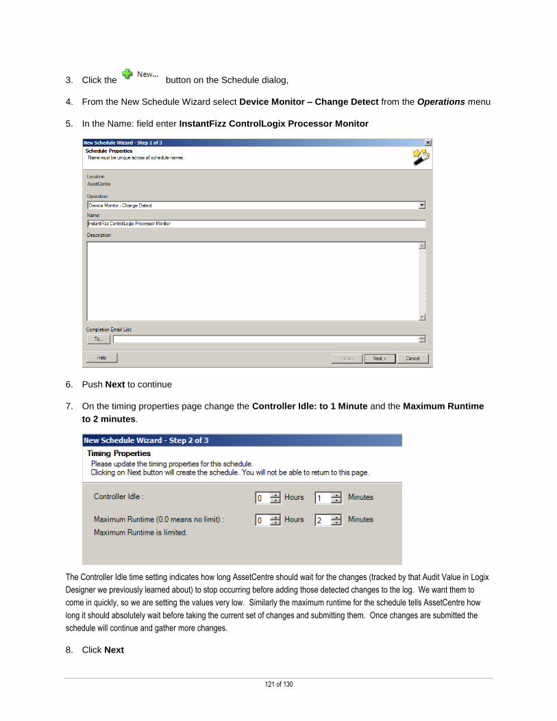
121 of 130
3. Click the button on the Schedule dialog,
4. From the New Schedule Wizard select Device Monitor – Change Detect from the Operations menu
5. In the Name: field enter InstantFizz ControlLogix Processor Monitor
6. Push Next to continue
7. On the timing properties page change the Controller Idle: to 1 Minute and the Maximum Runtime
to 2 minutes.
The Controller Idle time setting indicates how long AssetCentre should wait for the changes (tracked by that Audit Value in Logix
Designer we previously learned about) to stop occurring before adding those detected changes to the log. We want them to
come in quickly, so we are setting the values very low. Similarly the maximum runtime for the schedule tells AssetCentre how
long it should absolutely wait before taking the current set of changes and submitting them. Once changes are submitted the
schedule will continue and gather more changes.
8. Click Next

122 of 130
9. From the Operations Properties dialog expand the InstantFizz container and select the IF2_Demo
Logix PAC
10. Once the controller is selected on the right side of the screen change the Copy Controller Log to
Audit Log value to True
11. Push Save and Finished to create the schedule.
12. Once the schedule is created in the lower left field you will see that AssetCentre is now creating a
connection to the controller.

123 of 130
13. After a few seconds the status will change to Change detect in process. This indicates that
AssetCentre has successfully connected and is waiting changes to occur.
14. Recall from earlier that we set our controller, through Logix Designer, to monitor changes to the key
switch mode. Once again turn the key on the controller from REM to PROG to RUN to REM.
15. Wait approximately 1 minute for the Change detect in progress status to disappear from the
AssetCentre schedule.
16. Once the status clears click the Logs tab once again near the top of the screen, and be sure you are
looking at the Audit Log
REM PROG RUN REM

124 of 130
17. You should now see several new logs, indicated in bold type, similar to the image below:
18. Select the message at the top of the list that says Keyswitch mode change in the message field.
Looking at the details of the audit message you can see what is captured, in many cases, the previous value and the new value
to give context to the user in regards to the change that was made.
19. Switch back to the Logs tab and click the Event Log button
20. Select the entry of the message that says: Change Detect Complete
AssetCentre/InstantFizz/IF2_Demo Logix PAC
21. In the lower field you will see the information about this change detection schedule, such as the
location of the controller on the network and when this entry was made.
22. Double click on the paper clip by the event message that says:

125 of 130
23. Click the View button to view the change report.
This report is produced and stored with a quick report of all the changes that occurred during the last
detection event. This report can be automatically emailed to a list of recipients upon creation.
24. Close the report PDF.
25. Close the attachment dialog.
26. From the menu along the top of the FactoryTalk AssetCentre Client click the Searches button
27. From the searches screen click the button
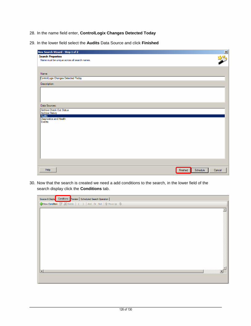
126 of 130
28. In the name field enter, ControlLogix Changes Detected Today
29. In the lower field select the Audits Data Source and click Finished
30. Now that the search is created we need a add conditions to the search, in the lower field of the
search display click the Conditions tab.
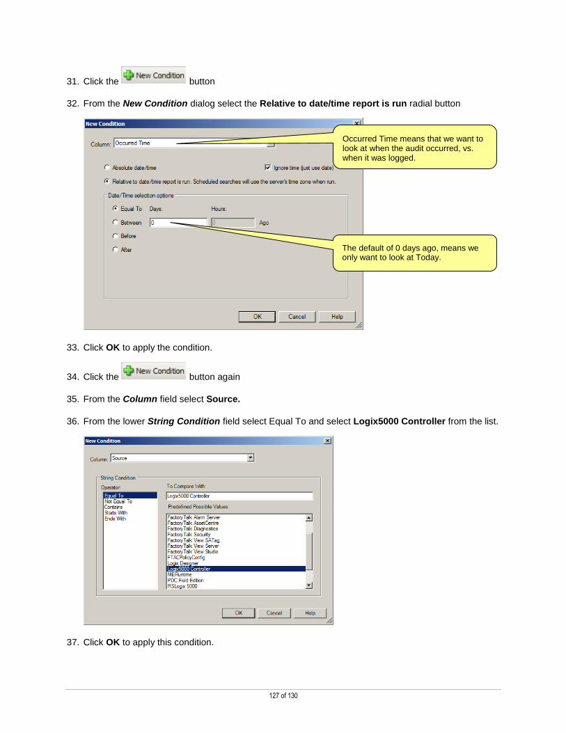
127 of 130
31. Click the button
32. From the New Condition dialog select the Relative to date/time report is run radial button
33. Click OK to apply the condition.
34. Click the button again
35. From the Column field select Source.
36. From the lower String Condition field select Equal To and select Logix5000 Controller from the list.
37. Click OK to apply this condition.
Occurred Time means that we want to look at when the audit occurred, vs. when it was logged.
The default of 0 days ago, means we only want to look at Today.
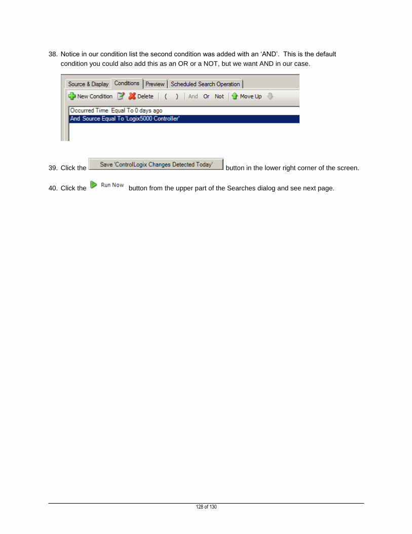
128 of 130
38. Notice in our condition list the second condition was added with an ‘AND’. This is the default
condition you could also add this as an OR or a NOT, but we want AND in our case.
39. Click the button in the lower right corner of the screen.
40. Click the button from the upper part of the Searches dialog and see next page.

129 of 130
41. You should have a report that looks similar to this, but with today’s date:
Design Tip: This report was created in FactoryTalk AssetCentre to grab all the changes on this controller that occurred today. You could also expand this report by adding the Event Messages for the IF2_DEMO produced by the RA Disaster Recovery Agent to include details on when backups were performed on this controller. Additionally, you could configure this report to collect only the changes made in a past few hours, days, etc.… to compare to a previous report.
42. Close FactoryTalk AssetCentre.
43. Close Logix Designer, saving any changes.
This completes the Change Management for ControlLogix Programmable Automation Controllers section of this lab.

130 of 130
Publication CE-DM131E-EN-E — November 2014 Copyright© 2014 Rockwell Automation, Inc. All rights reserved.
Supersedes Publication CE-DM131D-EN-E — June 2014