l1-che-std-011 1500vdc overhead wiring … · engineering standard – electrical networks...
TRANSCRIPT

Engineering Standard – Electrical Networks
L1-CHE-STD-011 1500VDC OVERHEAD WIRING SYSTEM Version: 2
ELECTRICAL NETWORKS STANDARD 1500VDC OVERHEAD WIRING SYSTEM
MEST 000002-02 Version: 2 Effective from: 1st July 2018
L1-CHE-STD-011
Approving Manager: Chief Engineer Approval Date: 01/07/2018 Next Review Date: 01/07/2021 PRINTOUT MAY NOT BE UP-TO-DATE; REFER TO METRO INTRANET FOR THE LATEST VERSION Page 2 of 53
Approval
Amendment Record
Approval Date Version Description
02/05/2013 1
Initial Release under MTM. Supersedes the following Standards:
1. VRIOGS 010.5 Train Overhead Design Standard,
2. PTC D001467 Train Overhead Design Standards for The Electrification of New Routes - 1997 (Issue 5),
3. PTC D001468 Train Overhead Design Standards for The Construction of New Railway Overhead Works - 1997 (Issue 3), and
4. PTC D001469 Train Overhead Design Standards for The Rehabilitation of Existing Routes - 1997 (Issue 3)
01/07/2018 2 Major re-write.
Document previously titled OVERHEAD LINE ELECTRIFICATION
ELECTRICAL NETWORKS STANDARD 1500VDC OVERHEAD WIRING SYSTEM
MEST 000002-02 Version: 2 Effective from: 1st July 2018
L1-CHE-STD-011
Approving Manager: Chief Engineer Approval Date: 01/07/2018 Next Review Date: 01/07/2021 PRINTOUT MAY NOT BE UP-TO-DATE; REFER TO METRO INTRANET FOR THE LATEST VERSION Page 3 of 53
PREFACE
This Standard will be managed under the Engineering Standards Development Procedure (L1-CHE-PRO-032).
As documents are uncontrolled once printed, it is imperative to check the currency of the Document on The Depot or the MTM’s Document Portal which is available externally at https://documentportal.metrotrains.com.au.
All MTM Standards and Specifications are periodically reviewed, and new editions are published which incorporate learnings and Technical Notes (formerly known as Design Practice Notes). Technical Notes are issued between editions which correct any errors or ambiguities contained in an MTM Standard/Specification. Standards and Specifications may also be withdrawn and/or replaced.
In the event of conflicts or discrepancies between different types of technical documents, refer to the order of precedence as defined in ‘Chief Engineer’s Guideline Engineering Standards Listing’ (L1-CHE-GDL-005).
Note: Any clarification described in a Technical Note or Design Practice Note shall take precedence over the impacted clause or clauses in the associated MTM Standard/Specification.
In the event a clause within a Standard/Specification is not achievable a waiver will need to be raised, please refer to the ‘Engineering Waiver Procedure’ - L1-CHE-PRO-001.
Note: MTM does not have the authority to grant waivers on any Standards/Specifications or clauses within a Standard/Specification which relate to Government Regulations or Legislation, e.g. Electricity Safety Act, Electrical Safety Regulations (Energy Save Victoria), Disability Discrimination Act.
ELECTRICAL NETWORKS STANDARD 1500VDC OVERHEAD WIRING SYSTEM
MEST 000002-02 Version: 2 Effective from: 1st July 2018
L1-CHE-STD-011
Approving Manager: Chief Engineer Approval Date: 01/07/2018 Next Review Date: 01/07/2021 PRINTOUT MAY NOT BE UP-TO-DATE; REFER TO METRO INTRANET FOR THE LATEST VERSION Page 4 of 53
Table of Contents 1 Purpose ........................................................................................................................... 6
2 Scope ............................................................................................................................... 6
3 Abbreviations .................................................................................................................. 6
4 Glossary of Terms .......................................................................................................... 7
5 Definitions ..................................................................................................................... 11
6 References and Legislations ....................................................................................... 12
7 Related Documents ...................................................................................................... 12
MTM References ............................................................................................................ 12 Industry References and Legislation .............................................................................. 14
Australian References .................................................................................................... 14
International References ................................................................................................. 15
8 Safety and Environmental ............................................................................................ 16
9 OHW Design Principles ................................................................................................ 17
10 1500V DC OHW Design Criteria ................................................................................... 18
Mechanical and Electrical Clearances ............................................................................ 18
Station Clearances.......................................................................................................... 19
Separation of Overhead Wiring Structures and Low Voltage Apparatus ....................... 19
Climatic conditions .......................................................................................................... 19 Line speed ...................................................................................................................... 20
Continuous Current Ratings ........................................................................................... 20
Sectionalising .................................................................................................................. 20
Airgaps ............................................................................................................................ 21
Span lengths ................................................................................................................... 23
Tension lengths ............................................................................................................... 24 Tensioning equipment .................................................................................................... 25
Overhead Wiring Conductors ......................................................................................... 25
Section Insulators ........................................................................................................... 36
Points, Crossings and Turnouts ...................................................................................... 36
Yards and Sidings ........................................................................................................... 36 Cables ............................................................................................................................. 37
Switches and Isolators .................................................................................................... 38
Insulation coordination .................................................................................................... 39
Earthing and bonding ...................................................................................................... 39
Refurbished OHW ........................................................................................................... 40
Staging OHW .................................................................................................................. 43

ELECTRICAL NETWORKS STANDARD 1500VDC OVERHEAD WIRING SYSTEM
MEST 000002-02 Version: 2 Effective from: 1st July 2018
L1-CHE-STD-011
Approving Manager: Chief Engineer Approval Date: 01/07/2018 Next Review Date: 01/07/2021 PRINTOUT MAY NOT BE UP-TO-DATE; REFER TO METRO INTRANET FOR THE LATEST VERSION Page 5 of 53
11 OHW Structures and Support ...................................................................................... 44
General Principles........................................................................................................... 44
Gauge clearance............................................................................................................. 44
Structural loading and deflection limits ........................................................................... 45
Portals and two-track cantilevers .................................................................................... 45 Drop verticals .................................................................................................................. 46
Under-line bridges and viaducts ..................................................................................... 46
Over-line Bridges ............................................................................................................ 46
Support and registration equipment ................................................................................ 47
Connectors and fasteners ............................................................................................... 48 Small part Steel work ...................................................................................................... 48
Pollution and Corrosion Protection ................................................................................. 49
12 Design Documentation and Certification .................................................................... 50
General ........................................................................................................................... 50 Electrical Diagrams ......................................................................................................... 50
Tension Length diagrams ............................................................................................... 50
Layout Plans ................................................................................................................... 51
Profile Drawings .............................................................................................................. 51
Cross Section Drawings ................................................................................................. 52
Other OHW design information ....................................................................................... 52
ELECTRICAL NETWORKS STANDARD 1500VDC OVERHEAD WIRING SYSTEM
MEST 000002-02 Version: 2 Effective from: 1st July 2018
L1-CHE-STD-011
Approving Manager: Chief Engineer Approval Date: 01/07/2018 Next Review Date: 01/07/2021 PRINTOUT MAY NOT BE UP-TO-DATE; REFER TO METRO INTRANET FOR THE LATEST VERSION Page 6 of 53
1 Purpose To define the standards required for the design and construction of the traction wiring, cables
and related equipment for the Melbourne Metropolitan Railway.
2 Scope This standard applies to the design and construction of all new electrification projects for the
Melbourne Metropolitan Railway Network.
This standard also applies to the upgrading of the existing traction wiring, distribution lines, cables and related equipment.
The standard applies to works on the Infrastructure Lease and to works undertaken on other land which are intended to expand or enhance the provision of passenger services and to form part of the Infrastructure Lease.
MTM Head of Engineering - Electrical shall be consulted in cases where there are perceived to be uncertainties, conflicts or ambiguities as to the requirements or the intent of this standard.
3 Abbreviations AC Alternating current
AS Australian Standard
ATM Along-track movement
BWA Balance weight anchor (contact wire only)
DC Direct current
EPR Earth potential rise
ESV Energy Safe Victoria
FBWA Full balance weight anchor (contact and catenary wires)
HDPE High-density polyethylene
HV High voltage
LV Low voltage
MPA Mid-point anchor
MTM Metro Trains Melbourne Pty Ltd
OHW Overhead wiring
PTC Public Transport Corporation
PTV Public Transport Victoria
SFAIRP So far as is reasonably practicable
TTC Two track cantilever
XLPE Cross-linked polyethylene

ELECTRICAL NETWORKS STANDARD 1500VDC OVERHEAD WIRING SYSTEM
MEST 000002-02 Version: 2 Effective from: 1st July 2018
L1-CHE-STD-011
Approving Manager: Chief Engineer Approval Date: 01/07/2018 Next Review Date: 01/07/2021 PRINTOUT MAY NOT BE UP-TO-DATE; REFER TO METRO INTRANET FOR THE LATEST VERSION Page 7 of 53
4 Glossary of Terms
6 foot The area located between two separate tracks (generally the area between the up and down tracks)
Airgap Airgaps are formed by overlapping contact wires and catenaries at the beginning and ends of tension lengths where the conductors are taken to the tensioning devices or fixed anchor.
Alignment - OHW The position of the OHW relative to the (superelevated) centreline of the track.
Alignment - track The centreline or other reference line of the track or tracks in both plan and profile.
Along-track Movement (ATM)
The migration of the OHW, induced by tensioning equipment, due to thermal expansion or contraction of the conductors.
Ambient temperature The weather related temperature of the OHW, which excludes temperature effects due to current in the conductors.
Auto-tensioned (AT) equipment
OHW conductors terminated by balance weights or other approved tensioning devices to maintain constant tension over a specified range of conductor temperatures by compensating for conductor thermal expansion and contraction.
Auxiliary feeder Conductor(s) both physically and electrically parallel to the catenary to provide voltage and/or current support
Balance weight anchor
Auto-tensioning of the contact wire only whilst the catenary wire is terminated at a fixed tension at a given temperature – not to be used for new works.
Bi-directional Able to operate in all directions. In the context of this document, bi-direction refers to the ability of rollingstock to operate in both the up and down directions on a single track.
Blow-off The lateral displacement of a conductor due to wind force.
Bond An electrical connection between metal hardware (rails, structure etc.) that eliminates voltage difference.
Bridge arm A flexible support and registration used in auto-tensioned equipment at low encumbrance areas such as bridges
Cantilever The component which supports the catenary insulator at a defined position horizontally and vertically above the track centreline
Catenary wire The conductor wire from which the contact wire is suspended.
Clearance point The point the pantograph is clear of a converging or diverging wire at cross-overs and turnouts
Contact scissor
A prohibited airgap arrangement where the contact wires do not run parallel at the strike point (ie do not have equal gradients at the strike point) and instead the strike point is at a single point where the two contact wires have opposite gradients
Contact wire Solid conductor used to supply electric energy to rail vehicles through current collection equipment.
Contact wire height Distance from the top of the rail to the underside of the contact wire, measured perpendicular to the canted or super elevated centreline of track.
ELECTRICAL NETWORKS STANDARD 1500VDC OVERHEAD WIRING SYSTEM
MEST 000002-02 Version: 2 Effective from: 1st July 2018
L1-CHE-STD-011
Approving Manager: Chief Engineer Approval Date: 01/07/2018 Next Review Date: 01/07/2021 PRINTOUT MAY NOT BE UP-TO-DATE; REFER TO METRO INTRANET FOR THE LATEST VERSION Page 8 of 53
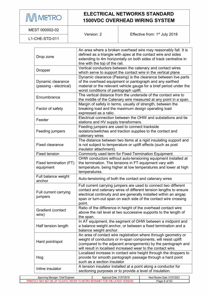
Drop zone
An area where a broken overhead wire may reasonably fall. It is defined as a triangle with apex at the contact wire and sides extending to 4m horizontally on both sides of track centreline in line with the top of the rail.
Dropper Vertical conductors between the catenary and contact wires which serve to support the contact wire in the vertical plane
Dynamic clearance (passing - electrical)
Dynamic clearance (Passing) is the clearance between live parts of the overhead equipment or pantograph and any earthed material or the relevant vehicle gauge for a brief period under the worst conditions of pantograph uplift.
Encumbrance The vertical distance from the underside of the contact wire to the middle of the Catenary wire measured at any point in a span.
Factor of safety Margin of safety in terms, usually of strength, between the breaking load and the maximum design operating load expressed as a ratio.
Feeder Electrical connection between the OHW and substations and tie stations and HV supply transformers.
Feeding jumpers Feeding jumpers are used to connect trackside isolators/switches and traction supplies to the contact and catenary wires
Fixed clearance The distance between two items at a rigid insulating support and is not subject to temperature or uplift effects (such as post insulator attachment).
Fixed tension Commonly used term for Fixed Termination Equipment.
Fixed termination (FT) equipment
OHW conductors without auto-tensioning equipment installed at the termination. The tensions in FT equipment vary with temperature, being higher at low temperatures and lower at high temperatures.
Full balance weight anchor Auto-tensioning of both the contact and catenary wires
Full current carrying jumpers
Full current carrying jumpers are used to connect two different contact and catenary wires of different tension lengths to ensure electrical continuity and are generally installed within an airgap span or turn-out span on each side of the contact wire crossing point.
Gradient (contact wire)
Ratio of the difference in height of the overhead contact wire above the rail level at two successive supports to the length of the span.
Half tension length In AT equipment, the segment of OHW between a midpoint and a balance weight anchor, or between a fixed termination and a balance weight anchor.
Hard point/spot
An area of contact wire registration where through geometry or weight of conductors or in-span components, will resist uplift (compared to the adjacent arrangements) by the pantograph and will result in localised increased wear to the contact wire.
Hog Localised increase in contact wire height through the droppers to provide for smooth pantograph passage through a hard point such as a section insulator
Inline insulator A tension insulator installed at a point along a conductor for sectioning purposes or to provide a level of insulation.

ELECTRICAL NETWORKS STANDARD 1500VDC OVERHEAD WIRING SYSTEM
MEST 000002-02 Version: 2 Effective from: 1st July 2018
L1-CHE-STD-011
Approving Manager: Chief Engineer Approval Date: 01/07/2018 Next Review Date: 01/07/2021 PRINTOUT MAY NOT BE UP-TO-DATE; REFER TO METRO INTRANET FOR THE LATEST VERSION Page 9 of 53
In-span jumpers
In-span jumpers provide electrical continuity between the catenary and contact wires. They generally not required as all droppers are current carrying. In-span jumpers are only required where non-current carrying sliding droppers are used.
Insulated airgap
Electrical sectioning point formed by overlapping the ends of adjacent tension lengths, allowing for parallel running of overhead wiring, by a 380mm airgap between the two sets of equipment.
Kinematic envelope
A two dimensional cross-section of the shape of a rail vehicle that consists of the static outline plus the maximum permitted allowance for vertical and lateral movements/sway. It also includes any cant and curve effect associated with curved track and dynamic movements in response to track irregularity.
Mean equivalent span See Virtual Span Length
Midpoint anchor (MPA)
A point along an AT tension length where the catenary is restrained in order to prohibit the tendency of the overhead system to migrate to one end of the tension length over time.
Mid-span offset (static)
The distance from the centreline of a pantograph to where the contact wire can be positioned at the centre of a span under no-wind conditions
Neutral section
Section of a contact line provided with a sectioning point at each end and is electrically floating. It is used to prevent successive electrical sections being connected together by the passage of pantographs.
Pantograph sway The lateral displacement of the pantograph due to vehicle roll.
Pantograph uplift The distance the contact wire is lifted due to the pressure exerted by a passing pantograph.
Permissible mid-span offset
The maximum distance from the centreline of a pantograph to where the contact wire can be positioned at the centre of a span under no-wind conditions
Potential equalising jumpers
Potential equalising jumpers are designed to keep the electrical potential of two different adjacent conductors at the same potential and therefore prevent electrically floating sections being created. They are typically provided at locations such as the anchor span of an open airgap where the out-of-running wires are in close proximity to the in-running wires
Protective device
An open circuit device which short circuits under fault conditions such as spark gap, diode or automatic overvoltage relay device. It services to control the effects of stray currents (and the resultant electrolytic corrosion) and/or to provide electrical safety. Also referred to as a Voltage Limiting Device
Radial load Horizontal load comprising of static forces caused by a change in the direction of a conductor at a support or registration point.
Registration Restraint of a conductor (generally the contact wire) in the horizontal plane
Regulated Alternative term for Auto-Tensioned (AT) Equipment
Section Insulator A device installed in-line with the contact wire which provides for smooth pantograph passage as well as electrical isolation on either side of it.

ELECTRICAL NETWORKS STANDARD 1500VDC OVERHEAD WIRING SYSTEM
MEST 000002-02 Version: 2 Effective from: 1st July 2018
L1-CHE-STD-011
Approving Manager: Chief Engineer Approval Date: 01/07/2018 Next Review Date: 01/07/2021 PRINTOUT MAY NOT BE UP-TO-DATE; REFER TO METRO INTRANET FOR THE LATEST VERSION Page 10 of 53
Self-supporting anchor Anchor mast without a back-guy.
Side feeder A conductor(s) run in parallel to the OHW which is of a different electrical section
Sliding dropper A dropper used in areas of low encumbrance where a standard dropper won’t fit or will foul the pantograph.
Span length The length of the overhead contact wire between one support/suspension and the next.
Stagger The displacement of the contact wire measured perpendicular to the superelevated track centreline measured at the registration.
Stagger change The change in position of the contact wire at a registration point, relative to track centreline, as a result of the arc of rotation of the registration arm due to Along Track Movement.
Stagger sweep
Is the lateral movement of the contact wire across the pantograph in the course of its travel between any two registration points and is the total of such movement, either from one side to the other, or from one side towards the centre and back towards the same side.
Static clearance The distance between two items without the influence of external forces such as pantographs, temperature or wind.
Static clearance (electrical)
Static clearance is the clearance between the live parts of the overhead equipment which are not fixed, when not subject to pantograph pressure, and an overhead structure or earthed parts of the overhead equipment.
Static load gauge Maximum cross-section-profile of the vehicles using the rail network.
Stiction Term that refers to the “static friction‟ that can exist between two objects that needs to be overcome before the objects can move independently
Stray current Current which follows paths other than the return circuit.
Strike point/zone Position where converging contact wire meets with the pantograph head at airgaps, turnouts and cross-overs
Suspension Support of a conductor in the vertical plane
Swept envelope Kinematic envelope enlarged to allow for centre and end throw of the vehicle on horizontal and vertical curves.
System height The encumbrance measured at a suspension point
Tension length The length of overhead Wiring between two anchoring points and/or tensioning devices.
Tension loss (or change)
The change in along track tension (from the nominal tension) of auto-tensioned conductors due to the mechanical drag of cantilevers as temperature varies
Tensioning device
A termination device installed at each end of a tension length or one end of a half-tension length which by mechanical action of weights, pulleys, springs or other mechanisms, exerts a constant tension to a conductor whilst compensating for changes in length of the conductor.
Track cant Cross-slope or change in elevation between two rails. Also referred to as superelevation

ELECTRICAL NETWORKS STANDARD 1500VDC OVERHEAD WIRING SYSTEM
MEST 000002-02 Version: 2 Effective from: 1st July 2018
L1-CHE-STD-011
Approving Manager: Chief Engineer Approval Date: 01/07/2018 Next Review Date: 01/07/2021 PRINTOUT MAY NOT BE UP-TO-DATE; REFER TO METRO INTRANET FOR THE LATEST VERSION Page 11 of 53
Traction wiring volume
The area formed by the vertical height of the encumbrance (at support structures) and a horizontal width of three metres placed centrally around the track centreline. Refer STD_E0166
Versine The distance between a chord drawn between two support structures and the track curve measured at the centre-point of the span.
Virtual span length
Applies to fixed tension conductors over a tension length defined between strain points and is used in the change of state equation. Note: it is likely that linepost supports offer enough restrain to nullify the effect of virtual spans. Dewitts also act at strain points
Wind load (operational)
The maximum load imposed on a support or registration point due to a conductor under the highest operational wind speed condition
Wire run number A discrete number assigned to each tension length for identification and material control purposes.
5 Definitions
Area accessible to public
Area to which the public has unrestricted access. This includes but is not limited to:
• Station entrances
• Platforms
• Level crossings (both road and pedestrian crossings)
• Within 10m of a level crossing or pedestrian crossing
• Areas delineated by an approved fence
High voltage Equal to or exceeding 1000V AC or 1500V DC
Infrastructure lease Is defined as the meaning in the Franchise Agreement.
Low voltage As defined by Australian/NZ Standards (<1000V AC or <1500V DC)
New works
Modification at, or replacement of more than 25% of structures in a half-tension length in the case of existing regulated catenary, or full-tension length in the case of existing fixed catenary
Nominal voltage Voltage by which an installation or part of an installation is designated
Restricted area Area for which access is only permitted for authorised persons
Shall (normative) Is used as the descriptive word to express a requirement that is mandatory to achieve conformance to the standard.

ELECTRICAL NETWORKS STANDARD 1500VDC OVERHEAD WIRING SYSTEM
MEST 000002-02 Version: 2 Effective from: 1st July 2018
L1-CHE-STD-011
Approving Manager: Chief Engineer Approval Date: 01/07/2018 Next Review Date: 01/07/2021 PRINTOUT MAY NOT BE UP-TO-DATE; REFER TO METRO INTRANET FOR THE LATEST VERSION Page 12 of 53
Should (informative)
Is used as the descriptive word to express a requirement that is recommended in order to achieve compliance to the standard. “Should” can also be used if a requirement is a design goal but not a mandatory requirement.
6 References and Legislations The hierarchy of, and conformance to any requirements, legislations, standards or
specifications shall be as per the Chief Engineer’s Guideline – Engineering Standards Listing – L1-CHE-GDL-005.
The design and construction of electrical installation works for the railway are to comply with the Electrical Safety (Installations) Regulations 2009.
7 Related Documents
MTM References
Document Number Title
L0-SQE-PLA-005 Environmental Management Plan
L1-CHE-GDL-005 Chief Engineer’s Guideline – Engineering Standards Listing
L1-CHE-MAN-005 Electrical Networks Engineering Manual
L1-CHE-PRO-001 Standard Waiver Procedure
L1-CHE-PRO-004 Type Approval Procedure
L1-CHE-PRO-031 Engineering Change Procedure
L1-CHE-PRO-037 MTM Tree Management Procedure
L1-CHE-SPE-001 Electrical Networks Specification Contact wire Hard-drawn copper 161mm2
L1-CHE-SPE-017 Transmission Wire Hard-Drawn Copper 19/2.14 70mm2
L1-CHE-SPE-019 Technical Specification for catenary wire hard-drawn copper 37/2.5 181mm2
L1-CHE-SPE-054 Technical Specification for flexible dropper wire tin-bearing copper 7/7/0.5 9.6mm2
L1-CHE-SPE-058 Technical Specification for bare flexible annealed copper jumper wire 37/7/0.70 100mm2
ELECTRICAL NETWORKS STANDARD 1500VDC OVERHEAD WIRING SYSTEM
MEST 000002-02 Version: 2 Effective from: 1st July 2018
L1-CHE-STD-011
Approving Manager: Chief Engineer Approval Date: 01/07/2018 Next Review Date: 01/07/2021 PRINTOUT MAY NOT BE UP-TO-DATE; REFER TO METRO INTRANET FOR THE LATEST VERSION Page 13 of 53
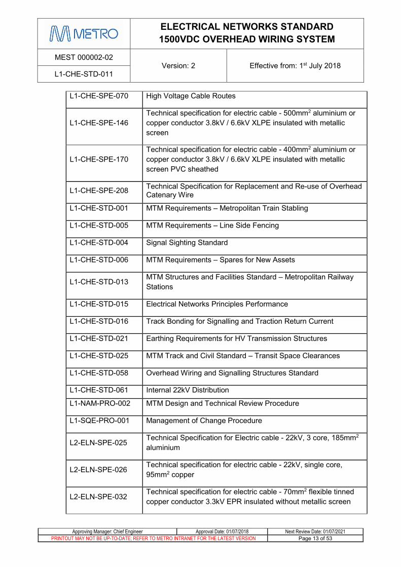
L1-CHE-SPE-070 High Voltage Cable Routes
L1-CHE-SPE-146 Technical specification for electric cable - 500mm2 aluminium or copper conductor 3.8kV / 6.6kV XLPE insulated with metallic screen
L1-CHE-SPE-170 Technical specification for electric cable - 400mm2 aluminium or copper conductor 3.8kV / 6.6kV XLPE insulated with metallic screen PVC sheathed
L1-CHE-SPE-208 Technical Specification for Replacement and Re-use of Overhead Catenary Wire
L1-CHE-STD-001 MTM Requirements – Metropolitan Train Stabling
L1-CHE-STD-005 MTM Requirements – Line Side Fencing
L1-CHE-STD-004 Signal Sighting Standard
L1-CHE-STD-006 MTM Requirements – Spares for New Assets
L1-CHE-STD-013 MTM Structures and Facilities Standard – Metropolitan Railway Stations
L1-CHE-STD-015 Electrical Networks Principles Performance
L1-CHE-STD-016 Track Bonding for Signalling and Traction Return Current
L1-CHE-STD-021 Earthing Requirements for HV Transmission Structures
L1-CHE-STD-025 MTM Track and Civil Standard – Transit Space Clearances
L1-CHE-STD-058 Overhead Wiring and Signalling Structures Standard
L1-CHE-STD-061 Internal 22kV Distribution
L1-NAM-PRO-002 MTM Design and Technical Review Procedure
L1-SQE-PRO-001 Management of Change Procedure
L2-ELN-SPE-025 Technical Specification for Electric cable - 22kV, 3 core, 185mm2 aluminium
L2-ELN-SPE-026 Technical specification for electric cable - 22kV, single core, 95mm2 copper
L2-ELN-SPE-032 Technical specification for electric cable - 70mm2 flexible tinned copper conductor 3.3kV EPR insulated without metallic screen

ELECTRICAL NETWORKS STANDARD 1500VDC OVERHEAD WIRING SYSTEM
MEST 000002-02 Version: 2 Effective from: 1st July 2018
L1-CHE-STD-011
Approving Manager: Chief Engineer Approval Date: 01/07/2018 Next Review Date: 01/07/2021 PRINTOUT MAY NOT BE UP-TO-DATE; REFER TO METRO INTRANET FOR THE LATEST VERSION Page 14 of 53
L2-INF-PLA-001 MTM Electric Line Clearance Plan
L2-INF-PLA-004 MTM Tree Management Procedure
L4-CHE-FOR-015 Overhead Line Electrification Functional Requirements Form
L4-CHE-FOR-016 MTM Standard - Traction Substations and Tie Stations
L4-ELN-INF-007 Electrical Networks Information Sheet – Overhead Wiring TMP Zone Map
L4-NAM-INF-001 Metro Network Map – Line Speeds
N/A MTM Document Portal: https://documentportal.metrotrains.com.au
Industry References and Legislation
Document Number Title N/A Victorian Traction Industry Electrical Safety Rules 2014 - revised
May 2017 (The Orange Book)
N/A Standard Conditions for Electric Power Overhead Lines on or over land vested in VicTrack
N/A Electrical Safety Act 1998
N/A Code of Practice for Electrolysis Mitigation 2015
N/A Electricity Safety (Electric Line Clearance) Regulations 2015
N/A Electricity Safety (Bushfire Mitigation) Regulations 2013
S.R No. 151/2009 Electricity Safety (Cathodic Protection) Regulations 2009
S.R No. 164/2009 Electricity Safety (Installations) Regulations 2009
Australian References
Document Number Title
AS 1170.2:2011 Structural design actions – Wind actions
AS 1214:2016 Hot-dip galvanized coatings on threaded fasteners (ISO metric course thread series)
AS 4100:1998 Steel structures
AS 4436:1996 Guide for the selection of insulators in respect of polluted conditions
AS 4680:2006 Hot dip galvanised (zinc) coatings on fabricated ferrous articles
AS 5100:2017 Bridge Design

ELECTRICAL NETWORKS STANDARD 1500VDC OVERHEAD WIRING SYSTEM
MEST 000002-02 Version: 2 Effective from: 1st July 2018
L1-CHE-STD-011
Approving Manager: Chief Engineer Approval Date: 01/07/2018 Next Review Date: 01/07/2021 PRINTOUT MAY NOT BE UP-TO-DATE; REFER TO METRO INTRANET FOR THE LATEST VERSION Page 15 of 53
AS/NZS 1768:2007 Lightning Protection
AS/NZS 3000:2007 Wiring Rules – 2007 Electrical Installations
International References
Document Number Title BSEN 50122-1:2011+A4:2017
Railway applications - Fixed installations - Electrical safety, earthing and the return circuit. Protective provisions against electric shock
EN 50119:2009 Railway Applications – Fixed installations – Electric traction Overhead contact lines
EN 50125:2014 Railway Applications – Environmental conditions for equipment. Rolling stock and on-board equipment
EN 50317:2012 Railway Applications – Current collection systems – Requirements for the validation and measurement of the dynamic interaction between pantograph and Overhead contact line
EN 50367:2012 Railway applications – Current collection systems – Technical criteria for the interaction between pantograph and Overhead line (to achieve free access)

ELECTRICAL NETWORKS STANDARD 1500VDC OVERHEAD WIRING SYSTEM
MEST 000002-02 Version: 2 Effective from: 1st July 2018
L1-CHE-STD-011
Approving Manager: Chief Engineer Approval Date: 01/07/2018 Next Review Date: 01/07/2021 PRINTOUT MAY NOT BE UP-TO-DATE; REFER TO METRO INTRANET FOR THE LATEST VERSION Page 16 of 53
8 Safety and Environmental Safety and risk assessments shall be undertaken for overhead line electrification projects,
addressing all areas of specification, design, construction, operation and maintenance of the traction wiring, distribution lines, cables and related equipment.
The approach to the operation and maintenance of the traction wiring, distribution lines, cables and related equipment shall be based on the principle of providing safe and functional electric traction and other supplies in so far as is reasonably practicable (SFAIRP).
The design, construction and operation of the traction wiring, distribution lines, cables and related equipment shall comply with the current revision of MTM Environmental Management Plan. Refer to L0-SQE-PLA-005.

ELECTRICAL NETWORKS STANDARD 1500VDC OVERHEAD WIRING SYSTEM
MEST 000002-02 Version: 2 Effective from: 1st July 2018
L1-CHE-STD-011
Approving Manager: Chief Engineer Approval Date: 01/07/2018 Next Review Date: 01/07/2021 PRINTOUT MAY NOT BE UP-TO-DATE; REFER TO METRO INTRANET FOR THE LATEST VERSION Page 17 of 53
9 OHW Design Principles Overhead line electrification shall be designed and constructed to provide for the safe and
reliable operation of electric trains of the types, at the speed and at the service frequency given in L4-CHE-FOR-015 - Overhead Line Electrification Functional Requirements Form and any relevant additional requirements issued by the State.
The electrical parameters comprising the incoming supply feeder voltages, currents, number of supply points, network reliability and redundancy shall be in accordance with L1-CHE-STD-015 - MTM Electrical Networks Principles and Performance Standard.
The mechanical and electrical parameters of the design and construction of the overhead line electrification of each mainline shall be independent of adjacent mainlines and sidings.
Insulation flash-over due to insulator failure or lightning strike may damage track based signalling equipment. Therefore masts and portal structures supporting traction wiring shall not be used to also support bare high voltage alternating current conductors.
All overhead support structures shall be provided with a current path to rail through a protective device (refer section 0) and/or provided with secondary insulation as per the agreed earthing & bonding philosophy and L1-CHE-STD-016 – Track Bonding for Signalling and Traction Return Current
Only materials listed on the current Metro Trains Melbourne Approved Engineering Product List shall be used – refer L1-CHE-PRO-004 appendix.
Where new materials or systems are to be introduced with the design and construction of the overhead line electrification, the materials and systems shall be subject to type approval for use on the Melbourne Metropolitan Train Network. Refer to L1-CHE-PRO-004
All auxiliary feeders shall be attached to the same structures used to support the catenary wires of the same electrical section with the exception of auxiliary feeder termination structures. Independent structures for the support of auxiliary feeders are not permitted.
Refer to L1-CHE-STD-061 for requirements for Internal 22kV Distribution design.
The OHW shall be designed to accommodate the maximum rolling stock outline as described in drawing STD_R0008.
OHW structure design and position shall take into account and adhere to all signal sighting requirements outlined in L1-CHE-STD-004 – Signal Sighting Standard.
ELECTRICAL NETWORKS STANDARD 1500VDC OVERHEAD WIRING SYSTEM
MEST 000002-02 Version: 2 Effective from: 1st July 2018
L1-CHE-STD-011
Approving Manager: Chief Engineer Approval Date: 01/07/2018 Next Review Date: 01/07/2021 PRINTOUT MAY NOT BE UP-TO-DATE; REFER TO METRO INTRANET FOR THE LATEST VERSION Page 18 of 53
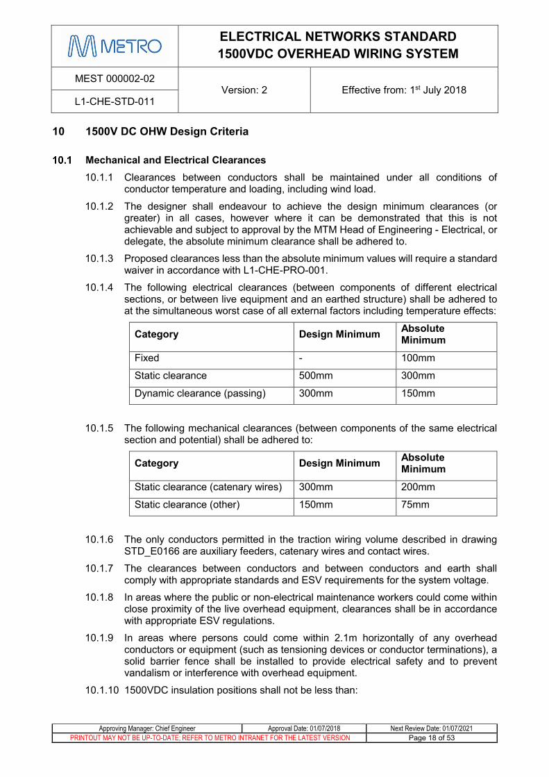
10 1500V DC OHW Design Criteria
Mechanical and Electrical Clearances 10.1.1 Clearances between conductors shall be maintained under all conditions of
conductor temperature and loading, including wind load.
10.1.2 The designer shall endeavour to achieve the design minimum clearances (or greater) in all cases, however where it can be demonstrated that this is not achievable and subject to approval by the MTM Head of Engineering - Electrical, or delegate, the absolute minimum clearance shall be adhered to.
10.1.3 Proposed clearances less than the absolute minimum values will require a standard waiver in accordance with L1-CHE-PRO-001.
10.1.4 The following electrical clearances (between components of different electrical sections, or between live equipment and an earthed structure) shall be adhered to at the simultaneous worst case of all external factors including temperature effects:
Category Design Minimum Absolute Minimum
Fixed - 100mm
Static clearance 500mm 300mm
Dynamic clearance (passing) 300mm 150mm
10.1.5 The following mechanical clearances (between components of the same electrical section and potential) shall be adhered to:
Category Design Minimum Absolute Minimum
Static clearance (catenary wires) 300mm 200mm
Static clearance (other) 150mm 75mm
10.1.6 The only conductors permitted in the traction wiring volume described in drawing STD_E0166 are auxiliary feeders, catenary wires and contact wires.
10.1.7 The clearances between conductors and between conductors and earth shall comply with appropriate standards and ESV requirements for the system voltage.
10.1.8 In areas where the public or non-electrical maintenance workers could come within close proximity of the live overhead equipment, clearances shall be in accordance with appropriate ESV regulations.
10.1.9 In areas where persons could come within 2.1m horizontally of any overhead conductors or equipment (such as tensioning devices or conductor terminations), a solid barrier fence shall be installed to provide electrical safety and to prevent vandalism or interference with overhead equipment.
10.1.10 1500VDC insulation positions shall not be less than:

ELECTRICAL NETWORKS STANDARD 1500VDC OVERHEAD WIRING SYSTEM
MEST 000002-02 Version: 2 Effective from: 1st July 2018
L1-CHE-STD-011
Approving Manager: Chief Engineer Approval Date: 01/07/2018 Next Review Date: 01/07/2021 PRINTOUT MAY NOT BE UP-TO-DATE; REFER TO METRO INTRANET FOR THE LATEST VERSION Page 19 of 53
10.1.10.1 5.0m from anchor terminations (except where a conductor is terminated to a portal or TTC bridge)
10.1.10.2 2.1m between live 1500V and other non-earthed conductors
10.1.10.3 0.6m between the back of the boom/registration arm insulator and mast (does not apply to where the boom/registration is attached to a drop vertical)
10.1.11 For Electric Line Clearance Plans and details, refer L2-INF-PLA-001.
Station Clearances 10.2.1 The design and construction of the traction wiring system shall ensure, the
maintenance of the station and its systems including those systems mounted on the station roof, do not require persons to approach within 4 metres of 1500VDC traction wiring equipment
10.2.2 All conductors associated with the traction wiring system, including those at earth potential but excluding bonding cables, shall not pass over platforms or station buildings.
10.2.3 The station designer and overhead designer shall coordinate the designs to ensure that the constructed stations and overhead system comply with the provisions of the STD_E0001 and Electricity Safety (Installations) Regulations except for the provisions of Tables 225.2 and 226.
10.2.4 For general station requirements, refer L1-CHE-STD-013
Separation of Overhead Wiring Structures and Low Voltage Apparatus 10.3.1 Under no circumstances are low voltage lighting and power installations and the
structures supporting the overhead wiring structures to be electrically connected.
10.3.2 As a general principle, apparatus supplied at low voltage and all low voltage cables are to be separated from overhead wiring support structures by a minimum distance of 2 metres.
10.3.3 Where it is necessary for low voltage apparatus and cables to be in physical contact with overhead wiring support structures, the apparatus and cables shall be insulated to a level of 3000V to protect the low voltage installation in the event of failure of the traction supply insulation.
Climatic conditions 10.4.1 The range of ambient temperatures for which the OHW conductors shall be designed
for is 0°C through to the maximum system design temperature of 60°C
10.4.2 The OHW shall be designed to operate within the prescribed climatic conditions:
Description Minimum Maximum Average Ambient shade temperature
0°C 45°C
Yearly average temperature
20°C

ELECTRICAL NETWORKS STANDARD 1500VDC OVERHEAD WIRING SYSTEM
MEST 000002-02 Version: 2 Effective from: 1st July 2018
L1-CHE-STD-011
Approving Manager: Chief Engineer Approval Date: 01/07/2018 Next Review Date: 01/07/2021 PRINTOUT MAY NOT BE UP-TO-DATE; REFER TO METRO INTRANET FOR THE LATEST VERSION Page 20 of 53
Intensity of solar radiation
1087 W/m2
Isokeraunic level 10
10.4.3 Ice loading shall not be considered
10.4.4 The following shall be designated as polluted/corrosive areas:
10.4.4.1 Areas defined as “Seaside Area” in L4-ELN-INF-007
10.4.4.2 All areas within 1500m of sea or within 200m of a river estuary
10.4.4.3 Areas covered by structures where insulators are not washed by action of rain (such as overbridges, station canopies over the track and the like)
10.4.4.4 All tunnel areas
10.4.4.5 Areas where the OHW is regularly subjected to diesel fumes
10.4.4.6 Enclosed maintenance areas
10.4.4.7 Altona Loop (due to proximity to oil refineries)
Line speed 10.5.1 The OHW shall be designed for the maximum line speed in the area to
L4-NAM-INF-001 or any known future line speed increases.
10.5.2 The design and construction of the traction wiring system shall not set the line speed.
Continuous Current Ratings 10.6.1 The OHW shall be designed such as to operate with a continuous current as defined
in L4-CHE-FOR-015 and any relevant power modelling/simulation reports.
Sectionalising 10.7.1 The electrical sectionalising of the overhead wiring system shall be developed in
consultation with MTM and be compatible with MTM’s Safety Management System.
10.7.2 The overhead wiring system shall be divided into electrical sections as required for the operation of trains and the electrical protection of the wiring system and the trains under fault conditions.
10.7.3 The overhead wiring between substations and tie stations on mainlines are referred to as sections and each is to be provided with a unique section number provided by MTM following the established numbering procedure.
10.7.4 At junctions, the sectionalising (and the mechanical construction) shall be arranged for the trains operating to the timetable to remain supplied by the mainline section. Where there are differing routing requirements for morning, afternoon and off-peak services, the sectionalising shall be based on the morning peak services routing.
10.7.5 Mainline sections shall be energised at all times by two independent circuit breakers.
10.7.6 Sidings and maintenance depots can be supplied by a single source but shall be supplied by independent circuit breakers.

ELECTRICAL NETWORKS STANDARD 1500VDC OVERHEAD WIRING SYSTEM
MEST 000002-02 Version: 2 Effective from: 1st July 2018
L1-CHE-STD-011
Approving Manager: Chief Engineer Approval Date: 01/07/2018 Next Review Date: 01/07/2021 PRINTOUT MAY NOT BE UP-TO-DATE; REFER TO METRO INTRANET FOR THE LATEST VERSION Page 21 of 53
10.7.7 Electrical sections shall be fed from lineside switches located at substations or tie-stations.
10.7.8 Where deemed operationally required by MTM, electrical sections shall be provided with a backup supply from an adjacent electrical section through a line-side switch (B-switch).
10.7.9 Sectionalising shall be provided at junctions to permit the operation of the junction with closure of the adjacent mainlines for maintenance and emergency response purposes.
10.7.10 Sectionalising at junctions and nominated operational boundary stations shall be designed and constructed in conjunction with the signalling system to permit the termination and turn back of trains as required.
10.7.11 The particular sectionalising requirements for new overhead wiring provided to junctions and for the refurbishment of the existing wiring system shall be as given in L4-CHE-FOR-015 - Overhead Line Electrification Functional Requirements Form.
Airgaps
10.8.1 Mechanical Arrangements 10.8.1.1 Airgaps shall be formed over three spans to drawing Q6257 or four spans
to drawing Q6370.
10.8.1.2 Preference is to install airgaps on tangent track and formed over three spans.
10.8.1.3 Airgaps formed over 1 or 2 spans are not permitted with the exception of in sidings subject to clause 10.15.1.2.
10.8.1.4 Scissoring of the contact wire at airgaps is not permitted.
10.8.1.5 Airgaps including contact wires at different tensions shall be as per drawing D3452
10.8.1.6 A combination of fixed system and auto tensioned catenary system in a single airgap is not permitted.
10.8.2 Electrical Arrangements 10.8.2.1 The electrical connections at airgaps may be one of four types, as required
at the particular location:
• Open
• Switched
• Jumpered
• Closed
10.8.2.2 Open airgaps include inline insulators in the overhead conductors to provide complete electrical separation between different electrical sections. They are typically located adjacent to substations and tie-stations.

ELECTRICAL NETWORKS STANDARD 1500VDC OVERHEAD WIRING SYSTEM
MEST 000002-02 Version: 2 Effective from: 1st July 2018
L1-CHE-STD-011
Approving Manager: Chief Engineer Approval Date: 01/07/2018 Next Review Date: 01/07/2021 PRINTOUT MAY NOT BE UP-TO-DATE; REFER TO METRO INTRANET FOR THE LATEST VERSION Page 22 of 53
10.8.2.3 Switched airgaps are constructed with inline insulators in the overhead conductor (as per open airgaps); however they can be electrically opened or closed via a lineside switch. They are typically located between substations/tie-stations and provide a means of sub-sectioning.
10.8.2.4 Jumpered airgaps are constructed with inline insulators in all conductors (as per open airgaps); however the conductors are bridged by a removable flexible conductor to form one continuous electrical section. These jumper conductors may be removed to convert the Jumpered airgap to an Open airgap as required for operational reasons.
10.8.2.5 Closed airgaps are constructed without inline insulators and do not have a means to be opened. The conductors are bridged by a flexible conductor to form one continuous electrical section. Closed airgaps shall only be installed with approval by the MTM Chief Engineer, or delegate.
10.8.2.6 In Open, Switched and Jumpered airgaps, long-rod insulators shall be placed in auxiliary feeders such as to be adjacent to the insulators in the nearest catenary – refer D3774
10.8.3 Location of airgaps 10.8.3.1 For new projects, the design and construction of airgaps shall be
coordinated with substation, signalling and station design and construction.
10.8.3.2 The selection of Switched, Jumpered and Closed airgap locations shall be made in consultation with MTM who will take into account operational requirements including locations which may be required to form a point of isolation during normal works as well as during fault/emergency conditions.
10.8.3.3 Open airgaps shall be positioned such that the pantograph of a train stopped at a signal will not bridge the airgap. Minimum distances between signals and open airgaps depend on the type of rollingstock to be operated and are as follows:
Rolling Stock type/configuration
Minimum distance between signal and open airgap
Comeng, Siemens, X’Trapolis 160m
HCMT – 6 and 7 car 160m
HCMT – 10 car 220m
10.8.3.4 Open and switched airgaps shall be shown on all applicable bonding plans
10.8.3.5 Airgaps, including anchor terminations shall not be placed at stations or across level crossings
10.8.3.6 Preference is for airgaps to be placed on level track, however where this is not practical, they shall in all cases be placed in areas of constant gradient track
10.8.3.7 Airgaps shall not be placed in areas of track with vertical curves or cant ramps.
10.8.3.8 Airgaps on all adjacent lines shall be in-line with each other. Staggering of adjacent airgaps is not permitted.

ELECTRICAL NETWORKS STANDARD 1500VDC OVERHEAD WIRING SYSTEM
MEST 000002-02 Version: 2 Effective from: 1st July 2018
L1-CHE-STD-011
Approving Manager: Chief Engineer Approval Date: 01/07/2018 Next Review Date: 01/07/2021 PRINTOUT MAY NOT BE UP-TO-DATE; REFER TO METRO INTRANET FOR THE LATEST VERSION Page 23 of 53
Span lengths 10.9.1 The span lengths for tangent and curved track shall be calculated taking into
account the following factors:
i. Wire tension
ii. Wire height
iii. Mid-span offset
iv. Blow off
v. Stagger effect
vi. Stagger change
vii. Encumbrance
viii. Minimum dropper lengths
ix. Alignment (versine or position in a curve)
x. Span differential (particularly on fixed tension conductors)
xi. Mast deflection
xii. Construction tolerances
xiii. Kinematic Envelope
xiv. Radial load
xv. Effect of varying span length by up to 2m if necessary to suit local conditions during foundation construction
10.9.2 The maximum span on tangent track shall be:
10.9.2.1 70 metres at 15kN contact wire tension
10.9.2.2 65 metres at 11.2kN contact wire tension
10.9.3 For all proposed spans lengths greater than those stated in 10.9.2, the Standard Waiver shall include calculations, in an agreed format, to prove that the design considers and achieves compliance with all of the factors stated in 10.9.1
10.9.4 Spans shall be shortened on curves to ensure that actual mid-span offset is less than the calculated permissible mid-span offset for each span. Refer drawing D3374.
10.9.5 The optimum position to prevent contact wire blow off is to design for the contact wire to be positioned mid span on the super elevated track centre line.
10.9.6 The maximum allowable contact wire displacement from the super elevated track centreline at the contract wire height at the centre of the span shall be 249mm under the worst operating conditions. Note that this shall include the static mid-span offset.
10.9.7 In order to prevent vibrational resonance within the contact wire, span lengths are to be varied such that adjacent spans are not equal so as far as is reasonably practicable.

ELECTRICAL NETWORKS STANDARD 1500VDC OVERHEAD WIRING SYSTEM
MEST 000002-02 Version: 2 Effective from: 1st July 2018
L1-CHE-STD-011
Approving Manager: Chief Engineer Approval Date: 01/07/2018 Next Review Date: 01/07/2021 PRINTOUT MAY NOT BE UP-TO-DATE; REFER TO METRO INTRANET FOR THE LATEST VERSION Page 24 of 53
10.9.8 No more than two adjacent span lengths which align with rolling stock pantograph spacing are permitted. The distances between adjacent pantographs of the Comeng, Siemens and Xtrapolis trains are 31m, 40m, 55m, 72m and 88m. For the Xtrapolis trains, the distances vary with the order of the carriages in the six carriage train. HCMT pantograph spacing are 22m, 38m, 44m and 60m, depending on the configuration or 6, 7 or 10 car set
Tension lengths 10.10.1 A tension length is defined as the length of contact/catenary wire between tensioning
devices.
10.10.2 A half-tension length is defined as the length of contact/catenary wire from a fixed anchor or MPA to the tensioning device.
10.10.3 Tension lengths and half-tension lengths shall be calculated such that the following criteria are satisfied:
10.10.3.1 The variation in conductor tension due to drag of any single cantilever or registration arm is calculated to not exceed ±5% relative to the nominal catenary wire tension.
10.10.3.2 The maximum tension variation anywhere within the half tension length, cantilever/registration drag is less than to ±7% relative to the nominal catenary wire tension. 3% tension variation is assumed for balance weight mass tolerance and stiction in the tensioning device.
10.10.3.3 Stagger change does not compromise the mid-span offsets and airgap opening of 380mm – this applies for all types of airgaps including closed airgaps.
10.10.3.4 The maximum stagger change due to along track movement is less than 50mm
10.10.3.5 No support or registration arrangement exceeds its maximum pivot angle. Refer to drawing D8214.
10.10.3.6 The tensioning device can operate satisfactorily throughout the whole conductor temperature range whilst taking into account conductor stretch/creep and construction tolerances.
10.10.4 Absolute maximum half-tension length shall be 650m
10.10.5 For all proposed half tension lengths greater than 550m or which contain a track radius of less than 800m, calculations shall be provided to MTM, in an agreed format, to prove that the criteria listed in 10.10.3 are satisfied
10.10.6 Subject to agreement with the relevant stakeholders including the over line bridge owner, and structural assessment, over line bridge faces may be used as mid-point anchors.
ELECTRICAL NETWORKS STANDARD 1500VDC OVERHEAD WIRING SYSTEM
MEST 000002-02 Version: 2 Effective from: 1st July 2018
L1-CHE-STD-011
Approving Manager: Chief Engineer Approval Date: 01/07/2018 Next Review Date: 01/07/2021 PRINTOUT MAY NOT BE UP-TO-DATE; REFER TO METRO INTRANET FOR THE LATEST VERSION Page 25 of 53
Tensioning equipment 10.11.1 Tensioning equipment shall be installed such that it will permit movement through
the whole conductor temperature range without binding. Refer D3902
10.11.2 Any grease nipples or other serviceable parts shall face towards the track and be easily accessible
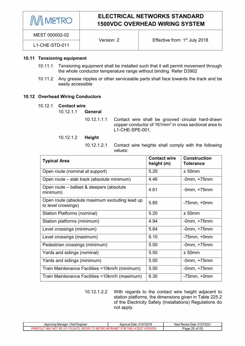
Overhead Wiring Conductors
10.12.1 Contact wire 10.12.1.1 General
10.12.1.1.1 Contact wire shall be grooved circular hard-drawn copper conductor of 161mm2 in cross sectional area to L1-CHE-SPE-001.
10.12.1.2 Height 10.12.1.2.1 Contact wire heights shall comply with the following
values:
Typical Area Contact wire height (m)
Construction Tolerance
Open route (nominal at support) 5.20 ± 50mm
Open route – slab track (absolute minimum) 4.46 -0mm, +75mm
Open route – ballast & sleepers (absolute minimum) 4.61 -0mm, +75mm
Open route (absolute maximum excluding lead up to level crossings) 5.85 -75mm, +0mm
Station Platforms (nominal) 5.20 ± 50mm
Station platforms (minimum) 4.94 -0mm, +75mm
Level crossings (minimum) 5.64 -0mm, +75mm
Level crossings (maximum) 6.10 -75mm, +0mm
Pedestrian crossings (minimum) 5.00 -0mm, +75mm
Yards and sidings (nominal) 5.50 ± 50mm
Yards and sidings (minimum) 5.00 -0mm, +75mm
Train Maintenance Facilities <10km/h (minimum) 5.00 -0mm, +75mm
Train Maintenance Facilities <10km/h (maximum) 6.30 -75mm, +0mm
10.12.1.2.2 With regards to the contact wire height adjacent to station platforms, the dimensions given in Table 225.2 of the Electricity Safety (Installations) Regulations do not apply.
ELECTRICAL NETWORKS STANDARD 1500VDC OVERHEAD WIRING SYSTEM
MEST 000002-02 Version: 2 Effective from: 1st July 2018
L1-CHE-STD-011
Approving Manager: Chief Engineer Approval Date: 01/07/2018 Next Review Date: 01/07/2021 PRINTOUT MAY NOT BE UP-TO-DATE; REFER TO METRO INTRANET FOR THE LATEST VERSION Page 26 of 53
10.12.1.2.3 The specified minimum contact wire height at level crossings shall be maintained for the whole span length which traverses the level crossing.
10.12.1.3 Tension 10.12.1.3.1 The contact wire shall be auto tensioned to provide a
nominally constant tension of 15kN over the full conductor temperature range.
10.12.1.3.2 11.2kN contact wire tension may be considered subject to a suitable and accepted value for money proposition or engineering case and endorsement by the MTM Head of Engineering - Electrical, or delegate, and where the line speed is <100km/h.
10.12.1.3.3 The contact wire shall be tensioned by an approved tensioning device
10.12.1.3.4 The wiring of mainline crossovers shall be designed and constructed with contact wire tension of 15kN (preferred) or 11.2kN.
10.12.1.3.5 The contact wire of yards and sidings is preferably installed at a tension of 15kN, however it may be constructed with a tension of 10kN or 11.2kN subject to approval by the MTM Head of Engineering - Electrical, or delegate.
10.12.1.4 Pre-sag 10.12.1.4.1 The nominal height of the Contact Wire at mid-span
shall be designed such that it is lower than at the supports to improve the current collection quality.
10.12.1.4.2 Pre-sag shall be applied to mainline OHW between the first and last droppers of a span in accordance with drawings D3909 and D3896.
10.12.1.4.3 Pre-sag is not required in the following:
10.12.1.4.3.1 Out of running spans
10.12.1.4.3.2 Spans containing a section insulator
10.12.1.4.3.3 Airgaps
10.12.1.4.3.4 Cross-overs
10.12.1.4.3.5 Sidings and depots
10.12.1.5 Up-lift 10.12.1.5.1 The uplift of the OHW caused by the passage of a
pantograph shall not exceed the following:
10.12.1.5.1.1 75mm at contact wire registration points in open route areas

ELECTRICAL NETWORKS STANDARD 1500VDC OVERHEAD WIRING SYSTEM
MEST 000002-02 Version: 2 Effective from: 1st July 2018
L1-CHE-STD-011
Approving Manager: Chief Engineer Approval Date: 01/07/2018 Next Review Date: 01/07/2021 PRINTOUT MAY NOT BE UP-TO-DATE; REFER TO METRO INTRANET FOR THE LATEST VERSION Page 27 of 53
10.12.1.5.1.2 75mm when under design minimum clearance conditions at overbridges and tunnels (refer 10.1.4)
10.12.1.5.1.3 50mm when under absolute minimum clearance conditions at overbridges and tunnels (refer 10.1.4)
10.12.1.6 Gradient 10.12.1.6.1 On open lines, the contact wire shall generally be
designed and constructed to be at a constant height of 5.2m above top of rail and zero gradient with respect to the rail.
10.12.1.6.2 Where bridges and level crossings require the traction wiring height to be changed, the rate of change of the contact wire height above top of rail shall be as follows.
10.12.1.6.2.1 For line speeds up to and including 60km/h: 1m per 300m
10.12.1.6.2.2 For line speeds greater than 60km/h: 1m per (5 x line speed in km/h) m
10.12.1.6.3 At the beginning and end of the gradient, the contact wire shall undertake vertical transitions which are to be formed by placing the contact wire at half of the gradient determined for the line speed.
10.12.1.6.4 The contact wire shall be parallel to the top of rail below over line bridges and at level crossings.
10.12.1.7 Stagger 10.12.1.7.1 The contact wire shall be staggered around the super
elevated track centreline to reduce the heating effect on the pantograph from the current flow between the contact wire and pantograph and maximise pantograph contact wearing strip life.
10.12.1.7.2 The contact wire stagger shall be determined to ensure that the resultant static radial load exceeds the calculated 28m/s wind load at the registration point.
10.12.1.7.3 For in-running contact wire below 5.40m above top of rail, the maximum stagger at the registration point shall be:
10.12.1.7.3.1 Tangent track: ±250mm from track centre
10.12.1.7.3.2 Curved track: ±300mm from track centre

ELECTRICAL NETWORKS STANDARD 1500VDC OVERHEAD WIRING SYSTEM
MEST 000002-02 Version: 2 Effective from: 1st July 2018
L1-CHE-STD-011
Approving Manager: Chief Engineer Approval Date: 01/07/2018 Next Review Date: 01/07/2021 PRINTOUT MAY NOT BE UP-TO-DATE; REFER TO METRO INTRANET FOR THE LATEST VERSION Page 28 of 53
10.12.1.7.4 For in-running contact wire above 5.40m above top of rail, the maximum stagger at the registration point shall be:
10.12.1.7.4.1 Tangent track: ±150mm from track centre
10.12.1.7.4.2 Curved track: ±200mm from track centre
10.12.1.7.5 At platform locations, maximum stagger towards the platform shall be 150mm from track centreline. Refer STD_E0179
10.12.1.7.6 In areas with short spans (such as under bridges), the stagger shall be maximised whilst taking into account the resultant radial load limitations of the registration arms
10.12.1.7.7 The stagger shall nominally be in increments of 50mm. Where critical, 10mm increments may be used.
10.12.1.7.8 The construction tolerance for stagger on tangent and curved track shall be ±25mm
10.12.1.7.9 Where two or more tracks run side by side, it is preferable that the stagger at each structure be to the same side of the track.
10.12.1.8 Splices 10.12.1.8.1 New contact wire shall be installed as a continuous
length for the whole tension length. Splicing or jointing of new contact wire is not permitted between terminations or between cut-in insulators.
10.12.1.8.2 If a contact wire splice is required for staging purposes, it shall preferably be installed in the out of running section.
10.12.1.8.3 Where a splice is required in an in-running section, it shall be positioned no less than 5m from a registration or support point, and shall be clear of any overhead fittings, jumpers, cross-contact bars and the like.
10.12.1.8.4 Where new contact wire is spliced to existing contact wire, the new contact wire shall be filed down to ensure a smooth pantograph transition across the splice

ELECTRICAL NETWORKS STANDARD 1500VDC OVERHEAD WIRING SYSTEM
MEST 000002-02 Version: 2 Effective from: 1st July 2018
L1-CHE-STD-011
Approving Manager: Chief Engineer Approval Date: 01/07/2018 Next Review Date: 01/07/2021 PRINTOUT MAY NOT BE UP-TO-DATE; REFER TO METRO INTRANET FOR THE LATEST VERSION Page 29 of 53
10.12.1.9 Wear & Safety Factor 10.12.1.9.1 All parts of the contact wire assembly shall, under all
conditions, including a maximum permissible wear, achieve the factor of safety as defined in D3898 for the nominal contact wire tension.
10.12.1.9.2 The contact wire shall have a maximum permissible cross sectional wear, as measured by the contact wire thickness from the running surface to the top of the wire, to the following values:
Contact wire tension Contact wire thickness
11.2kN >9mm
15kN >10mm
10.12.1.9.3 Existing contact wire may be reused where it can be demonstrated that it has a remaining serviceable life of >5 years and by having a minimum contact wire thickness as defined in clause 10.20.1.7.
10.12.2 Catenary Wire 10.12.2.1 General
10.12.2.1.1 The catenary wire shall be stranded circular copper conductor of 181mm2 cross-sectional area to L1-CHE-SPE-019.
10.12.2.2 Encumbrance/System Height 10.12.2.2.1 For mainline open line construction, the preferred
system height is a uniform 1.30m (nominal) at the catenary suspension points at 20kN catenary wire tension.
10.12.2.2.2 As required for over line bridges, level crossings, or interfaces between new and existing overhead wiring, the system height approaching these features and at the bridges and level crossings may be varied.
10.12.2.2.3 The preferred minimum encumbrance is 300mm. Where a lower encumbrance is necessary (for instance under low bridges and the like) approved low-encumbrance bridge arms and sliding droppers shall be used. Refer 10.12.7.8.
10.12.2.3 Tension 10.12.2.3.1 The catenary wire shall be auto tensioned to provide a
nominally constant tension of 20kN over the full conductor temperature range.

ELECTRICAL NETWORKS STANDARD 1500VDC OVERHEAD WIRING SYSTEM
MEST 000002-02 Version: 2 Effective from: 1st July 2018
L1-CHE-STD-011
Approving Manager: Chief Engineer Approval Date: 01/07/2018 Next Review Date: 01/07/2021 PRINTOUT MAY NOT BE UP-TO-DATE; REFER TO METRO INTRANET FOR THE LATEST VERSION Page 30 of 53
10.12.2.3.2 12kN or 15kN auto tensioned catenary wire may be considered subject to a suitable and accepted value for money proposition or engineering case and endorsement by the MTM Head of Engineering - Electrical, or delegate, and where the line speed is <100km/h.
10.12.2.3.3 The catenary wire shall be tensioned by an approved tensioning device
10.12.2.3.4 The wiring of mainline crossovers shall be designed and constructed with catenary wire auto-tensioned to 12kN, 15kN or 20kN in accordance with the mainline system.
10.12.2.3.5 The catenary wire of yards and sidings may be auto tensioned to 10kN, 11.2kN or 12kN, subject to approval by the MTM Head of Engineering - Electrical, or delegate.
10.12.2.4 Stagger 10.12.2.4.1 The catenary wire shall be staggered to be at all times
vertically above the contact wire that it is supporting with a construction tolerance of ±25mm.
10.12.2.5 Splices 10.12.2.5.1 Splices in new catenary wire are not allowed with the
exception of one at the interface to existing catenary.
10.12.2.5.2 Splices shall be rated at full load current, or shall be supplemented with a suitable parallel jumper
10.12.2.5.3 Splices shall be located between the first and second dropper connection points from an OHW support structure.
10.12.2.5.4 Splices shall be positioned as to not conflict with a dropper, feeder or jumper.
10.12.2.6 Safety factor 10.12.2.6.1 All parts of the catenary wire assembly shall, under all
conditions achieve the factor of safety as defined in D3898 for the nominal catenary wire tension.
10.12.3 Auxiliary feeders 10.12.3.1 General
10.12.3.1.1 The auxiliary feeder wire shall be stranded circular copper conductor of 181mm2 cross-sectional area to L1-CHE-SPE-019.
ELECTRICAL NETWORKS STANDARD 1500VDC OVERHEAD WIRING SYSTEM
MEST 000002-02 Version: 2 Effective from: 1st July 2018
L1-CHE-STD-011
Approving Manager: Chief Engineer Approval Date: 01/07/2018 Next Review Date: 01/07/2021 PRINTOUT MAY NOT BE UP-TO-DATE; REFER TO METRO INTRANET FOR THE LATEST VERSION Page 31 of 53
10.12.3.1.2 Where possible, all auxiliary feeders shall be positioned within 800mm of track centreline (ie vertically between the rail gauge) such that a failure of the wire will result in contact with the rail or a train and subsequent circuit breaker operation
10.12.3.1.3 Auxiliary feeders shall be positioned on the far side of the catenary wire relative to a platform.
10.12.3.1.4 Where it can be demonstrated that positioning auxiliary feeders within 800mm of track centreline is not practical (for example due to low over-line bridges or the like) and subject to approval by the MTM Head of Engineering - Electrical, or delegate, auxiliary feeders may be positioned above the 6 foot.
10.12.3.1.5 Auxiliary feeders shall be connected via a jumper arrangement (to drawing Q6052) to the catenary within 2 metres from the centreline of each overhead wiring supporting structure unless the span length is less than 40m, in which case, feeders shall be connected to the catenary via a jumper arrangement at each second supporting structure.
10.12.3.1.6 Where multiple conductors forming the same auxiliary feeder arrangement are installed, they shall be run side by side and clamped together using Auxiliary Feeder clamp assemblies to drawing STD_E0218.
10.12.3.2 Tension 10.12.3.2.1 In general, the auxiliary feeder conductor shall be
installed as fixed tension equipment with a tension such that it will match the sag of the nearby loaded catenary wire. Nominally this tension will be 10kN at 20°C.
10.12.3.2.2 Where a fixed tension arrangement will not permit minimum clearance requirements over the full conductor temperature range, the auxiliary feeder may be auto-tensioned by an approved tensioning device.
10.12.3.3 Sag 10.12.3.3.1 The auxiliary feeder shall, at the maximum conductor
temperature and any ambient conditions and for all tolerances, maintain a minimum vertical separation above the in-running contact wire of 150mm.

ELECTRICAL NETWORKS STANDARD 1500VDC OVERHEAD WIRING SYSTEM
MEST 000002-02 Version: 2 Effective from: 1st July 2018
L1-CHE-STD-011
Approving Manager: Chief Engineer Approval Date: 01/07/2018 Next Review Date: 01/07/2021 PRINTOUT MAY NOT BE UP-TO-DATE; REFER TO METRO INTRANET FOR THE LATEST VERSION Page 32 of 53
10.12.3.4 Splices 10.12.3.4.1 Splices in the auxiliary feeder should be avoided.
Where splices are required, the following shall apply:
10.12.3.4.1.1 No more than 1 splice per conductor per 500m or per half-tension length if the auxiliary feeder is auto-tensioned
10.12.3.4.1.2 The splice shall be rated at full load current, or shall be supplemented with a suitable parallel jumper
10.12.3.4.1.3 Splice locations are to be recorded and provided to MTM
10.12.3.4.1.4 Where multiple auxiliary feeder conductors are installed, splices are to be staggered by a minimum of 1 span.
10.12.4 Side feeders 10.12.4.1 General
10.12.4.1.1 Preference is for side feeders to be run as a buried cable to section 10.16.2. Where this is not possible, it shall be stranded circular copper conductor of 181mm2 cross-sectional area to L1-CHE-SPE-019.
10.12.4.1.2 Aerial side feeders shall be positioned on the outside face of masts in order to provide the maximum possible separation to other electrical sections and shall in all cases be greater than 2.1 metres from adjacent conductors of a different electrical section.
10.12.4.1.3 Where multiple conductors forming the same electrical side feeder arrangement are installed, they shall be run side by side and clamped together using a suitably rated current carrying clamp or crimp uniformly within the span length at the following spacing:
10.12.4.1.3.1 30 metre intervals
10.12.4.1.3.2 15 metre intervals in exposed areas such as raised embankments and viaducts.
10.12.4.2 Tension 10.12.4.2.1 In general, the side feeder conductor shall be installed
as fixed tension equipment with a tension such that it will match the sag of the nearby loaded catenary wire. Nominally this tension will be 10kN at 20°C.

ELECTRICAL NETWORKS STANDARD 1500VDC OVERHEAD WIRING SYSTEM
MEST 000002-02 Version: 2 Effective from: 1st July 2018
L1-CHE-STD-011
Approving Manager: Chief Engineer Approval Date: 01/07/2018 Next Review Date: 01/07/2021 PRINTOUT MAY NOT BE UP-TO-DATE; REFER TO METRO INTRANET FOR THE LATEST VERSION Page 33 of 53
10.12.4.2.2 Where a fixed tension arrangement will not permit minimum clearance requirements over the full conductor temperature range, the side feeder may be auto-tensioned by an approved tensioning device.
10.12.4.3 Sag 10.12.4.3.1 The side feeder shall, at the maximum conductor
temperature and any ambient conditions, not sag to below 5.0m above ground level within the rail corridor and 5.64m over level crossings.
10.12.4.3.2 The side feeder shall, at the maximum conductor temperature and any ambient conditions, not sag to minimum 1500VDC conductor height and clearances requirements as stipulated by ESV – refer Electricity Safety (Installations) Regulations 2009.
10.12.4.4 Splices 10.12.4.4.1 Splices in the side feeder should be avoided. Where
splices are required, the following shall apply:
10.12.4.4.1.1 No more than 1 splice per conductor per 500m or per half-tension length if the side feeder is auto-tensioned
10.12.4.4.1.2 The splice shall be rated at full load current, or shall be supplemented with a suitable parallel jumper
10.12.4.4.1.3 Splice locations are to be recorded and provided to MTM
10.12.4.4.1.4 Where multiple side feeder conductors are installed, splices are to be staggered by a minimum of 1 span.
10.12.5 Electrolysis feeders 10.12.5.1 General
10.12.5.1.1 Electrolysis conductors shall be regarded as being at earth potential (ESV) for clearance requirements.
10.12.5.1.2 The preference is for electrolysis feeder conductors to be run as underground cable to L1-CHE-SPE-070.
10.12.5.1.3 Where the electrolysis feeder conductor is to be run as a bare overhead conductor, it shall be stranded circular copper conductor of 181mm2 cross-sectional area to L1-CHE-SPE-019 or aluminium conductor of 210mm2 cross-sectional area to L1-CHE-SPE-132.
10.12.5.1.4 Electrolysis conductors shall not pass over 1500VDC conductors and shall be run as an underground cable.

ELECTRICAL NETWORKS STANDARD 1500VDC OVERHEAD WIRING SYSTEM
MEST 000002-02 Version: 2 Effective from: 1st July 2018
L1-CHE-STD-011
Approving Manager: Chief Engineer Approval Date: 01/07/2018 Next Review Date: 01/07/2021 PRINTOUT MAY NOT BE UP-TO-DATE; REFER TO METRO INTRANET FOR THE LATEST VERSION Page 34 of 53
10.12.5.1.5 Electrolysis feeder conductors shall be mounted from the rear of masts away from the track in accordance with drawing D8010 and terminated in accordance with D8013. For portal structures, the electrolysis feeder conductors shall be similarly outside the structure.
10.12.5.2 Tension 10.12.5.2.1 Where electrolysis feeder conductors are run as bare
aerial conductors, it shall be installed as fixed tension equipment with a nominal tension of:
10.12.5.2.1.1 181mm2 copper - 8kN at 20°C.
10.12.5.2.1.2 210mm2 aluminium – 2.8kN at 20°C.
10.12.5.2.2 Where a fixed tension arrangement will not permit minimum clearance requirements over the full conductor temperature range, the electrolysis feeder shall be run as an underground cable.
10.12.5.3 Sag 10.12.5.3.1 The electrolysis feeder shall, at the maximum
conductor temperature and any ambient conditions, not sag to below minimum electrolysis conductor height and clearances requirements as stipulated by ESV – refer Electricity Safety (Installations) Regulations 2009.
10.12.5.4 Splices 10.12.5.4.1 Splices in the electrolysis feeder are to be avoided.
Where splices are required, the following shall apply:
10.12.5.4.1.1 Splices shall be of a crimped type to match the conductor size
10.12.5.4.1.2 No more than 1 splice per conductor per 700m
10.12.5.4.1.3 Splice locations are to be recorded and provided to MTM
10.12.6 Other Conductors / 3rd Party Services 10.12.6.1 The clearance to the Traction Wiring Volume shall be that appropriate
for the voltage of the crossing conductor as required by the Electrical Safety Act and Regulations.
10.12.6.2 The minimum voltage of aerial conductors permitted to cross above the traction wiring system is 11kV.
10.12.6.3 Conductors at earth potential shall not cross above 1500VDC conductors
10.12.6.4 Preference is for other conductors and 3rd party services to be installed as an underground crossing.

ELECTRICAL NETWORKS STANDARD 1500VDC OVERHEAD WIRING SYSTEM
MEST 000002-02 Version: 2 Effective from: 1st July 2018
L1-CHE-STD-011
Approving Manager: Chief Engineer Approval Date: 01/07/2018 Next Review Date: 01/07/2021 PRINTOUT MAY NOT BE UP-TO-DATE; REFER TO METRO INTRANET FOR THE LATEST VERSION Page 35 of 53
10.12.6.5 Low voltage conductors belonging to third parties are not permitted to be supported on railway overhead masts or structures.
10.12.6.6 All third party conductors crossing the railway shall conform to “Standard Conditions for Electric Power Overhead Lines on or over land vested in VicTrack” published by VicTrack.
10.12.6.7 Aerial conductors crossing the traction wiring system shall be limited to those conductors essential for operation of the railway and those belonging to third parties approved by the State.
10.12.6.8 Aerial conductors shall cross the railway perpendicular to the track centre line.
10.12.6.9 Aerial conductors shall not be placed in the Traction Wiring Volume and shall be designed and constructed to maintain clearance to the volume at all times and under all conditions of conductor temperature and loading, including wind load.
10.12.6.10 Low voltage conductors mounted on structures shall be insulated to a level of 3000V to protect the cable and reduce electrolysis risk in the event of failure of the traction supply insulation.
10.12.7 Droppers 10.12.7.1 Dropper conductors shall be flexible tin-bearing copper 7/7/0.5 9.6mm
to L1-CHE-SPE-054
10.12.7.2 Droppers shall be formed to drawing H6345
10.12.7.3 Droppers shall not be used such as to control contact wire stagger or mid-span offset and shall not have radial load applied to them.
10.12.7.4 Dropper spacing shall be as per drawing D3896 and D4355
10.12.7.5 Construction tolerance for dropper spacing shall be ±200mm and ±5° from vertical at 20°C
10.12.7.6 Flexible droppers shall be electrically conducting to ensure sharing of the current between the catenary and the contact wire in each overhead span.
10.12.7.7 The minimum flexible dropper length for an auto-tensioned system shall be 300mm.
10.12.7.8 Where the site conditions require the distance between the catenary and contact wire to be less than the prescribed minimum, with the exception of bridge arms, droppers which permit differential longitudinal movement between the conductors (sliding droppers) shall be installed to drawing D4747.
10.12.7.9 Sliding droppers shall be paralleled by flexible conductors between the catenary and the contact wire to ensure current load sharing.
10.12.7.10 Where sliding droppers are required, the first standard droppers on either side shall be doubled to provide a current path between the contact and catenary wires.

ELECTRICAL NETWORKS STANDARD 1500VDC OVERHEAD WIRING SYSTEM
MEST 000002-02 Version: 2 Effective from: 1st July 2018
L1-CHE-STD-011
Approving Manager: Chief Engineer Approval Date: 01/07/2018 Next Review Date: 01/07/2021 PRINTOUT MAY NOT BE UP-TO-DATE; REFER TO METRO INTRANET FOR THE LATEST VERSION Page 36 of 53
10.12.8 Jumpers 10.12.8.1 Jumper wire conductor shall be bare flexible annealed copper wire
37/7/0.70 100mm2 to L1-CHE-SPE-058
10.12.8.2 Jumpers shall be formed as per Q6052
10.12.8.3 Jumpers shall be arranged such as to permit the relative movements of all conductors with temperature variations.
Section Insulators 10.13.1 Section insulators are not permitted in the mainline with the exception of use in an
approved staging design – refer section 10.21.
10.13.2 Section insulators are permitted at cross-overs.
10.13.3 Section insulators shall be rated for the line speed of the track in which they are fitted.
10.13.4 Where a section insulator is installed, it shall be placed parallel to and within 50mm of the track centreline under static conditions, and adjusted to match the track cant and hogged as per manufacturer requirements. Refer drawing L9563
Points, Crossings and Turnouts
10.14.1 Mechanical Arrangements 10.14.1.1 Crossovers shall be formed in accordance with Q6251
10.14.1.2 Turnouts shall be formed in accordance with Q6251
10.14.1.3 The design and construction shall ensure that longitudinal movement of the conductors with temperature variation does not distort or disarrange the wiring.
10.14.1.4 Fittings shall not be connected to the contact wires in the fitting free zone for either the mainline or crossover pantograph moves with the exception of the cross contact bar.
10.14.2 Electrical Arrangements 10.14.2.1 If the electrical sectionalising plan necessitates a section insulator in
the turnout, it shall be installed beyond the clearance point
10.14.2.2 In the vicinity of the turnout, the contact wires and catenaries of both the tangent and diverging tracks shall be supplied from the mainline.
10.14.2.3 The diverging track in a turnout may be supplied from a dedicated circuit breaker where available. Alternatively it may be supplied from the mainline through a lineside switch.
Yards and Sidings 10.15.1 Yards and sidings shall be built to all current mainline standards with the exception
of the following:
10.15.1.1 Tensioning of the contact and catenary wires may be via single tensioning device with a yoke plate.

ELECTRICAL NETWORKS STANDARD 1500VDC OVERHEAD WIRING SYSTEM
MEST 000002-02 Version: 2 Effective from: 1st July 2018
L1-CHE-STD-011
Approving Manager: Chief Engineer Approval Date: 01/07/2018 Next Review Date: 01/07/2021 PRINTOUT MAY NOT BE UP-TO-DATE; REFER TO METRO INTRANET FOR THE LATEST VERSION Page 37 of 53
10.15.1.2 Airgaps formed over 1 or 2 spans are permitted in yards and sidings where it can be demonstrated that a standard airgap arrangement is impractical and subject approval by the MTM Head of Engineering - Electrical, or delegate.
10.15.1.3 The overhead structures may be used to support light fittings as per the lighting plan. The electrical insulation provisions in section 10.12.6.10 apply.
10.15.1.4 Lighting supported on parafil rope shall not cross through or over the OHW.
10.15.1.5 Anchor structures at the ends of sidings shall be position as per section 11.2 such that an errant train does not strike the structure and disarrange the overhead wiring for the sidings.
10.15.1.6 Where it can be demonstrated that masts cannot be offset at the ends of sidings, subject to approval from the MTM Head of Engineering - Electrical, or delegate, an approved contact wire run-off system to drawing STD_E0195 shall be used.
10.15.1.7 Sidings and yards shall be supplied by independent circuit breaker(s) which are independent from the mainline.
10.15.1.8 The electrical sectionalising shall be approved by MTM as it is driven by operational and electrical feeding requirements. Power feeding requirements shall be specified in the approved power system model.
10.15.1.9 Earth switches are not required unless specifically included in the functional requirements.
10.15.1.10 The siding lead-in road shall be independent wiring to ensure a failure in the siding does not impact the mainline.
Cables
10.16.1 General 10.16.1.1 Cable routes shall be as per L1-CHE-SPE-070 – High Voltage Cable
Routes.
10.16.2 DC cables 10.16.2.1 400mm2 DC cables shall be to L1-CHE-SPE-170. 10.16.2.2 500mm2 DC cables shall be to L1-CHE-SPE-146. 10.16.2.3 High voltage DC cables shall be sized for the voltage, load and fault
currents applicable to the location.
10.16.2.4 Positive cables originating in a substation or tie station shall have the screens of the cables bonded to the negative busbar within the switchgear. The screens at the other cable ends shall be insulated and sleeved with the insulation level applicable to the voltage rating of the cable.
10.16.2.5 Screens shall be insulated and sized to carry the traction system fault current for the duration of the fault clearing time of the applicable circuit breaker.

ELECTRICAL NETWORKS STANDARD 1500VDC OVERHEAD WIRING SYSTEM
MEST 000002-02 Version: 2 Effective from: 1st July 2018
L1-CHE-STD-011
Approving Manager: Chief Engineer Approval Date: 01/07/2018 Next Review Date: 01/07/2021 PRINTOUT MAY NOT BE UP-TO-DATE; REFER TO METRO INTRANET FOR THE LATEST VERSION Page 38 of 53
10.16.2.6 Positive cables between overhead wiring sections remote to a substation or tie station shall have the screens of the cables bonded to rail at one end of the cables only. The screens at the other cable ends shall be insulated and sleeved with the insulation level applicable to the voltage rating of the cable.
10.16.2.7 Positive cables shall be fitted with surge diverters to drawing D4763 applicable to the system voltage. The diverter shall be installed where the cable joins the overhead wiring system and be connected between the cable positive and earth.
10.16.2.8 Surge diverters shall be electrically connected within 300mm of the cable terminations.
10.16.2.9 Negative cables are not required to be screened. Negative cables shall be protected from damage and inadvertent contact with earth or any material in contact with earth.
10.16.3 Bonding cables 10.16.3.1 Bonding cables shall be 3kV insulated 70mm2 copper cable to L2-
ELN-SPE-032.
Switches and Isolators 10.17.1 A switch shall be provided at both ends of a 1500V DC cable
10.17.2 Each overhead wiring switch and isolator shall be placed such as to be clearly identified with the overhead wiring with which it is associated. Switches and isolators shall be labelled with the appropriate section number in accordance with the established naming principles.
10.17.3 Switch and isolator label plates shall be to drawing D6434
10.17.4 Switches and isolators for the overhead wiring shall preferably be mounted 6.0 metres above the operating ground level. Switches and isolators shall not be less than 5.5 metres above ground level.
10.17.5 Cable fed overhead switches and isolators shall be placed on masts separated by a minimum of 3.0m from any structure supporting the catenaries to provide adequate clearance to live equipment for maintenance staff
10.17.6 A flood light shall be provided at all switch locations to allow for safe personnel access to the switch at night. This light shall be:
10.17.6.1 Remotely operated from Electrol.
10.17.6.2 If remote operation is agreed with MTM as not being practical, then a solar powered light with keyed timer switch (light shall remain on for 30minutes) shall be provided.
10.17.7 Switch locations shall be provided with a flat operating pad to provide for safe access and operation of the switch/isolator. Refer to drawing STD_E0123.
ELECTRICAL NETWORKS STANDARD 1500VDC OVERHEAD WIRING SYSTEM
MEST 000002-02 Version: 2 Effective from: 1st July 2018
L1-CHE-STD-011
Approving Manager: Chief Engineer Approval Date: 01/07/2018 Next Review Date: 01/07/2021 PRINTOUT MAY NOT BE UP-TO-DATE; REFER TO METRO INTRANET FOR THE LATEST VERSION Page 39 of 53
Insulation coordination 10.18.1 The insulation of the overhead wiring shall be graded with the conductor
terminations having the highest level, the suspension insulators the next and the contact wire registration the lowest level.
10.18.2 The terminating insulators for the catenary, contact and auxiliary feeders shall be a polymeric insulator to drawing D7268.
10.18.3 The catenary and auxiliary feeders shall be supported on 15kV polymeric insulators to STD_E0147 or D7675.
10.18.4 Over line bridges may require different insulators but they shall be rated at 15kV or greater.
10.18.5 Where auxiliary feeders are installed, the supporting insulators shall be of the same type as for the catenary supports.
10.18.6 The contact wire registration shall be either a 200mm disc insulator to drawing STD_E0151 or polymeric to drawing D8214.
10.18.7 Electrical sections shall be separated by 15kV polymeric insulators in the catenary and contact wires where the contact wire is out of running. Where the contact wire is in running a section insulator as per L9563 and rated for the line speed shall be installed.
Earthing and bonding
10.19.1 General 10.19.1.1 Inherent in the design of the direct current traction system is the fact
that the connection of the live overhead conductor to earth will not give rise to a current sufficient to operate the protective circuit breakers. Fault currents are only detected between the overhead wiring system and rail/traction return.
10.19.1.2 All overhead support installations in platforms, cuttings, retaining walls, viaducts, tunnels (including interfaces with existing tunnels) shall require a detailed earthing and bonding report which identifies electrolysis and safety risks and their mitigations SFAIRP.
10.19.1.3 All overhead support installations on elevated structures shall require a detailed lightning study which identifies any safety risks and ensures that lightning strike does not put at risk other railway equipment.
10.19.1.4 Unless determined otherwise in the earthing and bonding report, the following provisions apply:
10.19.1.4.1 On open route structures outside of publically accessible areas, the mast shall be connected to rail via spark gap to drawing STD_E0161.
10.19.1.4.2 In areas accessible to the public, secondary insulation shall be provided as per drawing STD_E0179 and D8210.
10.19.1.4.3 No metallic objects (such a fences) shall be connected to overhead structures
ELECTRICAL NETWORKS STANDARD 1500VDC OVERHEAD WIRING SYSTEM
MEST 000002-02 Version: 2 Effective from: 1st July 2018
L1-CHE-STD-011
Approving Manager: Chief Engineer Approval Date: 01/07/2018 Next Review Date: 01/07/2021 PRINTOUT MAY NOT BE UP-TO-DATE; REFER TO METRO INTRANET FOR THE LATEST VERSION Page 40 of 53
10.19.1.4.4 Any earthed metallic objects placed within 2m of any overhead structure shall include touch potential risk mitigation measures such as insulating fence segments/panels or non-conductive covers as endorsed by the MTM Head of Engineering - Electrical, or delegate.
10.19.1.5 Overhead wiring supports attached to over and under line bridges shall be fitted with double insulation with the centre point of the insulator bonded directly to rail. Refer to drawing D3454 and STD_E0134.
10.19.1.6 Structures which are both accessible to the public and within the drop zone shall be subject to risk assessment to determine the electrical risk mitigations SFAIRP
10.19.2 Protective devices 10.19.2.1 All overhead support structures shall be provided with a current path to
rail through a protective device (typically a spark gap unless determined otherwise in an earthing and bonding study/report or if another strategy is used, such as secondary insulation) which will trip the substation protective devices in the event of an insulator or conductor failure
10.19.2.2 The position, quantity and type of protective device shall be specified by the designer in an Earthing, Bonding and Lightning report which has been endorsed by the MTM Head of Engineering - Electrical, or delegate.
10.19.2.3 Refer to L1-CHE-STD-016 - Track Bonding for Signalling and Traction Return Current for guidelines on the use of spark gaps, diodes and over-voltage protection devices.
10.19.2.4 The type and position of protective devices shall take into account maintenance requirements and accessibility
Refurbished OHW
10.20.1 General Principles 10.20.1.1 The clauses concerning refurbished OHW may be applied where the
works meets the definition of refurbished OHW as follows:
10.20.1.1.1 Existing regulated catenary systems – modification at, or replacement of less than 25% of the OHW structures in a half tension length.
10.20.1.1.2 Existing fixed catenary systems – modification at, or replacement of less than 25% of OHW structures in a full-tension length.
10.20.1.2 Where the works do not meet the definition of refurbished OHW, the provisions for new works shall apply.
10.20.1.3 All refurbished OHW installations shall be FBWA or upgradable to FBWA by installation of pivoting/inclined cantilevers for supports affected. This includes areas of fixed catenary.

ELECTRICAL NETWORKS STANDARD 1500VDC OVERHEAD WIRING SYSTEM
MEST 000002-02 Version: 2 Effective from: 1st July 2018
L1-CHE-STD-011
Approving Manager: Chief Engineer Approval Date: 01/07/2018 Next Review Date: 01/07/2021 PRINTOUT MAY NOT BE UP-TO-DATE; REFER TO METRO INTRANET FOR THE LATEST VERSION Page 41 of 53
10.20.1.4 The retention of fixed catenary systems is subject to:
10.20.1.4.1 Approval of the MTM Head of Engineering - Electrical, or delegate
10.20.1.4.2 The line speed is less than 100km/h
10.20.1.4.3 There being no level crossings in the tension length.
10.20.1.5 Where the line speed is, or is known to be able to be increased to, 100km/h or greater, the traction wiring shall be designed and constructed to all current mainline standards.
10.20.1.6 Where refurbished OHW construction interfaces with existing overhead and the existing contact wire is serviceable for five or more years, a splice is permitted.
10.20.1.7 A serviceable life of five or more years requires a minimum contact wire thickness, anywhere in the tension length, as follows:
Contact Wire Tension Minimum thickness from running surface to top of wire
11.2kN 10.0mm
15kN 11.0mm
10.20.1.8 Where a half-tension length contact wire contains 4 or more splices in the in-running section, the whole half-tension length shall be replaced. Additional splices are permitted in out of running sections only.
10.20.1.9 Existing catenary wire may be re-used subject to the following:
10.20.1.9.1 The catenary wire satisfies all inspection and testing criteria as per L1-CHE-SPE-208 – Technical Specification for Replacement and Reuse of Overhead Catenary Wire, and
10.20.1.9.2 A suitable and accepted value for money proposition or engineering case and endorsement by the MTM Head of Engineering - Electrical, or delegate.
10.20.1.10 Any fittings, clamps, brackets or other OHW equipment shall be subject to a detailed visual inspection and/or sample tested as required by MTM. Any damaged, worn or corroded components or any components which do not pass the testing criteria set by MTM shall be replaced.
10.20.1.11 The preferred tensions of the catenary and contact wire for refurbishment works are 20kN and 15kN respectively.
10.20.1.12 At line speeds of 100 km/h or lower, catenary tension of 15kN or 12kN and contact wire tension of 11.2kN are permissible subject to approval from the MTM Head of Engineering - Electrical, or delegate.

ELECTRICAL NETWORKS STANDARD 1500VDC OVERHEAD WIRING SYSTEM
MEST 000002-02 Version: 2 Effective from: 1st July 2018
L1-CHE-STD-011
Approving Manager: Chief Engineer Approval Date: 01/07/2018 Next Review Date: 01/07/2021 PRINTOUT MAY NOT BE UP-TO-DATE; REFER TO METRO INTRANET FOR THE LATEST VERSION Page 42 of 53
10.20.1.13 Section insulators installed in fixed tension catenary system are typically positioned within 5m of a catenary support point however the designer shall consider the effects of change in section insulator height through sag in the catenary wire.
10.20.2 Tension Length, Wiring Spans, Masts and Structures 10.20.2.1 Subject to condition assessment and any new requirements arising,
the refurbishment may use the existing structures.
10.20.2.2 All tension lengths, span lengths, and structural loading requirements shall comply with the requirements of new works, or subject to MTM Standard Waiver.
10.20.2.3 In mainline areas of fixed tension catenary, the maximum difference between two adjacent spans shall be less than 20m unless it can be demonstrated that there will no detrimental effects caused by tension imbalance on the catenary support.
10.20.3 Contact Wire Height, Stagger and Gradient 10.20.3.1 Refurbished works shall comply with the contact height, stagger and
gradient requirements for new works.
10.20.3.2 The minimum flexible dropper length for a fixed-tensioned system shall be 600mm for a fixed tension catenary wire system.
10.20.3.3 Where the site conditions require the distance between the catenary and contact wire to be less than the prescribed minimum (with the exception of bridge arms), droppers which permit differential vertical movement between the conductors (sliding droppers) shall be installed to drawing D4747 and paralleled by flexible conductors between the catenary and the contact wire to ensure current load sharing.
10.20.4 Over-line Bridges 10.20.4.1 Refurbished works on over-line bridges shall comply with the
requirements for new works, or subject to Standard Waiver against the relevant clause(s).
10.20.4.2 Mechanical and electrical clearance requirements shall be as for new works.
10.20.4.3 Earthing and bonding requirements shall be as for new works.
10.20.5 Stations 10.20.5.1 Overhead wiring arrangement modifications in station environs shall be
upgraded to comply with all earthing and bonding requirements for new works.
10.20.6 Points and Crossings 10.20.6.1 The provisions for new works shall apply.
10.20.6.2 The wiring of mainline crossovers shall be designed and constructed with contact wire tension of 15kN (preferred) or 11.2kN.

ELECTRICAL NETWORKS STANDARD 1500VDC OVERHEAD WIRING SYSTEM
MEST 000002-02 Version: 2 Effective from: 1st July 2018
L1-CHE-STD-011
Approving Manager: Chief Engineer Approval Date: 01/07/2018 Next Review Date: 01/07/2021 PRINTOUT MAY NOT BE UP-TO-DATE; REFER TO METRO INTRANET FOR THE LATEST VERSION Page 43 of 53
10.20.6.3 The wiring of mainline crossovers shall be designed and constructed with catenary wire minimum tension of 12kN or fixed tension to be compatible with the mainline construction.
10.20.6.4 If the mainline adjacent to any points and crossings is upgraded to FBWA, the turnout/crossover shall be upgraded to FBWA to current standards for new works.
10.20.7 Airgaps 10.20.7.1 Airgaps shall be modified to comply with the requirements for new
works.
10.20.7.2 At an interface between fixed and regulated catenary, the airgap shall be FWBA and a mid-point anchor shall act as the transition point between fixed and regulated catenary.
Staging OHW 10.21.1 Staging OHW is a temporary OHW arrangement which is put in place to facilitate
the construction/refurbishment of OHW as part of a strategy to mitigate safety risks and/or customer disruption.
10.21.2 Any staging OHW in service for more than 12 weeks are regarded as permanent OHW and shall be designed and constructed as such, and requires approval of standard waivers for any non-conformances.
10.21.3 The following aspects of the standard may be relaxed for the duration of the staging works, subject to the approval by the MTM Head of Engineering – Electrical, or delegate, and completing of a risk assessment:
10.21.3.1 Contact wire gradient where the line speed is <60km/h, may be increased to 1:200.
10.21.3.2 Span lengths in-excess of 70m provided the span length is not increased from existing and the designer provides calculations, in an agreed format, to prove that the design considers and achieves compliance with all of the factors stated in 10.9.1.
10.21.3.3 At airgaps involving both fixed and regulated catenaries, the preference is to install a MPA and regulate both catenaries in the airgap. However, an alternative solution for staging works is to place an additional structure in the middle of the airgap to provide mid-span support of the fixed tension catenary in order to limit sag of the fixed tension catenary wire.
10.21.3.4 Section insulators may be used in the mainline to provide for electrical isolation points during construction. The section insulators shall be removed upon completion of the project.
ELECTRICAL NETWORKS STANDARD 1500VDC OVERHEAD WIRING SYSTEM
MEST 000002-02 Version: 2 Effective from: 1st July 2018
L1-CHE-STD-011
Approving Manager: Chief Engineer Approval Date: 01/07/2018 Next Review Date: 01/07/2021 PRINTOUT MAY NOT BE UP-TO-DATE; REFER TO METRO INTRANET FOR THE LATEST VERSION Page 44 of 53
11 OHW Structures and Support
General Principles 11.1.1 For structural requirements other than those included below, refer L1-CHE-STD-
058.
11.1.2 The preferred overhead wiring support is a separate free standing mast for each track. Portal structures may be installed at stations and other locations over multiple tracks but shall be designed to give independent support and registration to the wiring of each track.
11.1.3 UC type masts and structures shall be drilled with a 22mm diameter hole in the web of the steel section at a height of 400mm above the base plate for the fitment of a spark gap or other fault protective device.
11.1.4 SHS or boxed type masts and structures shall have a suitable lug for the fitment of a spark gap or other protective device, drilled and positioned in accordance with clause 11.1.3.
11.1.5 The overhead structures shall be designed to support the load of the number of auxiliary feeders per track as defined in the power system modelling and shall in all cases support a minimum of two auxiliary feeders each of 181mm2 cross-section.
11.1.6 The overhead masts and structures shall be designed and constructed to support the loading of one electrolysis feeder conductor. For portal structures, the design shall provide for the loading of one electrolysis feeder conductor each side of the structure.
11.1.7 The requirement for the masts and structures to be capable of supporting the electrolysis feeder conductors applies whether or not a specific need for the electrolysis feeder conductors is identified at the design phase of a project.
11.1.8 Traction wiring supporting structures shall not be placed in passenger waiting and circulation areas on platforms. If necessary, portal structures spanning over passenger areas shall be provided.
11.1.9 The design shall specify if electrical bonding between the hold down bolts and foundation reinforcement steel is required.
11.1.10 Unless otherwise specified, the safety factor for overhead line fittings shall not be less than three.
Gauge clearance 11.2.1 Structure gauge envelope H as defined in L1-CHE-STD-025 – Track and Civil
Standard – Transit Space Clearances applies and shall be increased to compensate for curve and cant effect as required.
11.2.2 The 3.0m clearance is to be measured from the inside face of the OHW structure OR the closest part of any equipment mounted to the structure (such as balance weight assemblies, spark gap assemblies, control boxes or the like), whichever is less and shall be demonstrated to be compliant at any point between the top of rail and 3.66m above rail.

ELECTRICAL NETWORKS STANDARD 1500VDC OVERHEAD WIRING SYSTEM
MEST 000002-02 Version: 2 Effective from: 1st July 2018
L1-CHE-STD-011
Approving Manager: Chief Engineer Approval Date: 01/07/2018 Next Review Date: 01/07/2021 PRINTOUT MAY NOT BE UP-TO-DATE; REFER TO METRO INTRANET FOR THE LATEST VERSION Page 45 of 53
Structural loading and deflection limits 11.3.1 The OHW and structures shall be designed for an operational across-track wind
speed of 28m/s.
11.3.2 The overhead wiring and structures shall be designed for the ultimate state loading as per the MTM Overhead Wiring and Signalling Structures Standard - L1-CHE-STD-058.
11.3.3 Wind pressure on the OHW shall be taken from the following expression:
Pw = 0.613 x V2 x d x Cd N/m2
Where: V = wind velocity in m/s Cd = drag coefficient as per D3218 d = conductor diameter (m)
11.3.4 Mast deflection solely due to 28m/s operational wind speed shall not exceed 50mm at contact wire height.
11.3.5 Structures shall be designed to resist twisting or otherwise deforming when under unbalanced loads resulting from an OHW failure.
Portals and two-track cantilevers 11.4.1 Portal structures and two-track cantilevers shall be provided where single track
structures cannot be utilised at multi-track areas.
11.4.2 Portal structures shall be used in preference to two-track cantilevers unless it can be shown that a portal is impractical.
11.4.3 Portals and two-track cantilevers structures shall be designed to support independent cantilever support and registration thereby providing for the disarrangement of overhead wiring on one line without subsequent lines being affected.
11.4.4 Portal structures shall be designed to support auxiliary feeders for all tracks spanned.
11.4.5 Portal structures with knee-braces are not permitted where they will prevent independent registration
11.4.6 A maximum of 8 consecutive two-track cantilevers with legs allocated on the same side of the tracks shall be used as it imposes limitations on applying earth leads.
11.4.7 Two-track cantilevers are not permitted at structures adjacent to open, switched or jumpered airgaps unless it can be demonstrated that both tracks can be safely earthed and that earth leads can be kept clear of diesel rollingstock or rail mounted plant.

ELECTRICAL NETWORKS STANDARD 1500VDC OVERHEAD WIRING SYSTEM
MEST 000002-02 Version: 2 Effective from: 1st July 2018
L1-CHE-STD-011
Approving Manager: Chief Engineer Approval Date: 01/07/2018 Next Review Date: 01/07/2021 PRINTOUT MAY NOT BE UP-TO-DATE; REFER TO METRO INTRANET FOR THE LATEST VERSION Page 46 of 53
Drop verticals 11.5.1 Drop verticals shall be installed on portal and two-track cantilever structures to
support the OHW equipment on the far track. Preference is for the near track OHW equipment to be supported from the mast where possible.
11.5.2 Preference is for separate drop verticals for each track, however a single drop vertical supporting back to back cantilever and registration boom arrangements may be used in station environs or in other areas where it can be demonstrated that separate drop verticals for each track is impractical.
11.5.3 Drop verticals shall be minimum galvanised 150UC
11.5.4 Drop verticals supporting back to back cantilever arrangements shall be minimum galvanised 250UC
11.5.5 Drop verticals shall be a minimum of 100mm above the contact wire height
11.5.6 Drop verticals shall not encroach within the applicable clearance envelopes.
11.5.7 The horizontal distance of the face of a drop vertical from track centreline shall be a minimum of 1500mm and shall consider stagger, registration arm type, boom insulator size and applicable structure gauge clearances (refer L1-CHE-STD-025).
11.5.8 The bottom of all drop verticals shall include a through bolt or welded lug such as to prevent wrap around brackets sliding off the bottom of the drop vertical.
Under-line bridges and viaducts 11.6.1 Where the length of the underline bridge and the placement of overhead structures
permits, structures shall be constructed clear of the bridge deck and abutments.
11.6.2 Overhead structures shall be mounted to bridge piers
11.6.3 Where it is required to mount an overhead structure on a bridge deck, structure, viaduct or abutment, an earthing and bonding report shall be produced.
11.6.4 Raised viaducts shall require a lightning protection study.
Over-line Bridges 11.7.1 Where possible, the design shall endeavour to free-run all overhead wires under
bridges whilst satisfying the applicable clearance, contact wire height and encumbrance requirements.
11.7.2 Where the bridge construction and height is such as to require the catenary supports to be affixed to the bridge structure, the catenary supports and contact wire registrations shall be of a form that permits the longitudinal movement with temperature variation.
11.7.3 To limit the risk of foreign objects being placed on the overhead traction system from the over line bridge, the bridge is to be fitted with protective barriers. Refer drawing STD_E0001.
11.7.4 Protective barriers shall be vertical on the side of the bridge of a height of not less than 2.4 metres or horizontal in the form of a veranda above the wiring. Only one form of barrier is required at a location.

ELECTRICAL NETWORKS STANDARD 1500VDC OVERHEAD WIRING SYSTEM
MEST 000002-02 Version: 2 Effective from: 1st July 2018
L1-CHE-STD-011
Approving Manager: Chief Engineer Approval Date: 01/07/2018 Next Review Date: 01/07/2021 PRINTOUT MAY NOT BE UP-TO-DATE; REFER TO METRO INTRANET FOR THE LATEST VERSION Page 47 of 53
11.7.5 Vertical barriers shall be a minimum of 4 metres in length, symmetrical about the centre line of the track and extended to protect all conductors associated with the traction power system.
11.7.6 The horizontal barrier shall be attached to the bridge and form a veranda over the wiring to drawing D3462.
11.7.7 The veranda shall be formed such that water from the bridge or the veranda shall not flow and form a continuous stream between the bridge, veranda and any wiring or components at line potential.
Support and registration equipment
11.8.1 Catenary Supports 11.8.1.1 Unless spatially constrained, catenary shall be supported from inclined
cantilevers hinged at the mast or drop vertical to freely swing in the along-track direction to accommodate temperature movement and minimise torsional forces on the structural members in the event of a broken conductor. Refer Q6390 and D8243
11.8.1.2 For general mainline applications, cantilevers shall be at structure potential and as per drawing Q6390.
11.8.1.3 For low encumbrance applications use Q6405 and Q6386
11.8.1.4 For over-line bridges, use D4349
11.8.1.5 Live cantilevers are non-preferred, however where it can demonstrated that they are required, use Q6564
11.8.1.6 In areas of high radial load, consideration shall be given to the effect of radial load on the following:
11.8.1.6.1 Clearance between the angled suspension insulator and the cantilever frame
11.8.1.6.2 Catenary displacement in both planes
11.8.1.6.3 Stability of the cantilever on the inside of curves, especially during construction before the weight of the contact wire is added to the cantilever.
11.8.2 Contact Wire Registration 11.8.2.1 Registration to the contact wire shall be normally by a steady-arm to
drawing D3819 supporting a horizontal boom as depicted on drawing D8190.
11.8.2.2 The maximum boom length is 4500mm. For registrations requiring additional reach, use a registration extension bracket to STD_E0172.
11.8.2.3 Static Radial load on a boom pull-off registration arrangement shall be <1200N in order to avoid lifting the boom nose
11.8.2.4 Radial load on a boom push-off registration arrangement shall be <2000N to avoid bending the boom tube.
11.8.2.5 Where wind and radial load exceed 2.5kN, twin registration arms to D3814 shall be used

ELECTRICAL NETWORKS STANDARD 1500VDC OVERHEAD WIRING SYSTEM
MEST 000002-02 Version: 2 Effective from: 1st July 2018
L1-CHE-STD-011
Approving Manager: Chief Engineer Approval Date: 01/07/2018 Next Review Date: 01/07/2021 PRINTOUT MAY NOT BE UP-TO-DATE; REFER TO METRO INTRANET FOR THE LATEST VERSION Page 48 of 53
11.8.2.6 Where there is insufficient space for a boom registration, pull-off registrations can be used to D3453
11.8.2.7 All push-off registrations shall be from a boom.
11.8.2.8 Where required for electrical clearance reasons, insulated stead-arms and neutral booms shall be used in accordance with D8192
11.8.2.9 Anti-torsion bars (‘Z-bars’) in accordance with drawing D3675 shall be used to provide restraint against contact wire roll in places where a registration steady arm is not provided.
11.8.2.10 Knuckle arrangements are not permitted
11.8.3 Station environs 11.8.3.1 Neutral booms shall be installed at all registration and support points
through platforms. Refer STD_E0179
11.8.3.2 Overhead wiring masts, including fixtures and fittings required to be installed public areas (refer to definition in Section 5) shall be at earth potential and provided with secondary insulation to drawing D8210 and STD_E0179. Areas accessible to the public do not include areas accessed by trespass
11.8.4 Pull-offs, head-spans and cross-spans 11.8.4.1 Pull-offs and cross-spans provide conductor registration but not
support and shall be as per drawing D8250.
11.8.4.2 Pull-off registrations shall only be considered where the radial load is the greater of 600N or (1.10 x 28m/s wind load)
11.8.4.3 Cross-span arrangements are limited to yards and sidings only. They shall not be used on mainlines.
11.8.4.4 Single track pull-off arrangements on mainlines are non-preferred and may be used where a standard support/registration arrangement is not practical and subject to approval by the MTM Head of Engineering - Electrical, or delegate.
11.8.4.5 Multiple track pull-off arrangements are not permitted
11.8.4.6 Head span construction is not permitted.
Connectors and fasteners 11.9.1 Refer drawings D4450, D4451 and D4452.
11.9.2 Copper alloy fastenings shall be the only fastener type used for current carrying clamps on copper conductors. Non-copper conductors shall have suitable clamps designed to minimize dissimilar metal corrosion.
Small part Steel work 11.10.1 Small part steel work shall generally be in accordance with AS4100
11.10.2 All parts shall be permanently stamped with their respective drawing and/or part number
ELECTRICAL NETWORKS STANDARD 1500VDC OVERHEAD WIRING SYSTEM
MEST 000002-02 Version: 2 Effective from: 1st July 2018
L1-CHE-STD-011
Approving Manager: Chief Engineer Approval Date: 01/07/2018 Next Review Date: 01/07/2021 PRINTOUT MAY NOT BE UP-TO-DATE; REFER TO METRO INTRANET FOR THE LATEST VERSION Page 49 of 53
11.10.3 Channels, angles and flat steel shall be standard metric sized and cut and drilled to suit the requirements of the design.
11.10.4 All cuts and drills shall be completed and all burrs removed prior to hot-dip galvanising to AS4680
Pollution and Corrosion Protection 11.11.1 The design shall avoid moisture and debris collection pockets.
11.11.2 Weathering Steels (for example, Cor-Ten, 3Cr12) are not permitted.
11.11.3 All commercial grade steel and SG-iron castings shall be hot dipped galvanised to AS4680.
11.11.4 All commercial grade fasteners shall be hot dipped galvanised to AS1214.
11.11.5 Stainless steel fasteners shall be of grade 304 or 316 steel.
11.11.6 Steel wire ropes shall be greased as required by the manufacturer.
11.11.7 Cast-iron balance weights shall be installed in their natural state, that is, corrosion prevention is not necessary.
11.11.8 Suitable measures shall be taken to relieve the causes of metals subject to stress cracking, stress corrosion or hydrogen embrittlement.
11.11.9 Dissimilar metals shall not be connected together unless the electrolytic action between them is mitigated by the use of a proprietary item designed for dissimilar metals.
11.11.10 Aluminium components or conductors shall not be positioned below any copper components or conductors.
11.11.11 All plastics shall be ultra-violet radiation stabilised. HDPE is preferred.
11.11.12 Small Part Steelwork attached to third party concrete or steelwork shall have the contact surface painted with a heavy bitumastic compound to inhibit the ingress of water.

ELECTRICAL NETWORKS STANDARD 1500VDC OVERHEAD WIRING SYSTEM
MEST 000002-02 Version: 2 Effective from: 1st July 2018
L1-CHE-STD-011
Approving Manager: Chief Engineer Approval Date: 01/07/2018 Next Review Date: 01/07/2021 PRINTOUT MAY NOT BE UP-TO-DATE; REFER TO METRO INTRANET FOR THE LATEST VERSION Page 50 of 53
12 Design Documentation and Certification
General 12.1.1 The designer shall be responsible for the provision of all documents, data and
drawings, necessary for the satisfactory completion and performance of the works.
12.1.2 The design shall include interfaces to the existing system and any necessary interface stage work
12.1.3 The designer shall provide the design in accordance with the scope of work
12.1.4 All drawings shall be produced and stored as DMS compliant drawings in accordance with applicable PTV Infrastructure Drafting Standards.
12.1.5 Standard System Drawings are created and updated by MTM only. Any required updates should be provided to MTM as a marked up copy and preferably along with any supporting information and DGN files.
Electrical Diagrams 12.2.1 Electrical diagrams including the following:
• 1500VDC Sectionalising diagrams
• 22kV distribution diagrams
• Electrolysis diagrams
12.2.2 Electrical diagrams are to be provided as mark ups for discussion with and approval by the MTM Head of Engineering - Electrical, or delegate.
12.2.3 Electrical diagrams are MTM Engineering Controlled Diagrams and are updated, approved and published by MTM only.
Tension Length diagrams 12.3.1 A not-to-scale schematic showing the proposed tension lengths, airgap positions,
mid-point anchors and their relation to other important interfaces or infrastructure such as:
12.3.1.1 Track features such as points, crossings, turnouts
12.3.1.2 Signals
12.3.1.3 Substations
12.3.1.4 Switching points
12.3.1.5 Platforms
12.3.1.6 Bridges, overpasses, underpasses
ELECTRICAL NETWORKS STANDARD 1500VDC OVERHEAD WIRING SYSTEM
MEST 000002-02 Version: 2 Effective from: 1st July 2018
L1-CHE-STD-011
Approving Manager: Chief Engineer Approval Date: 01/07/2018 Next Review Date: 01/07/2021 PRINTOUT MAY NOT BE UP-TO-DATE; REFER TO METRO INTRANET FOR THE LATEST VERSION Page 51 of 53
Layout Plans 12.4.1 Layout plans provide a top down view on the OHW and shall include at a minimum
the following:
12.4.1.1 Track
12.4.1.2 Overhead wiring
12.4.1.3 Stagger magnitude and direction
12.4.1.4 Structure boxes, symbols and abbreviations to drawing STD_E0121
12.4.1.5 Signal positions
12.4.1.6 Bridges
12.4.1.7 Platforms
12.4.1.8 Other relevant geographic features
12.4.1.9 VicTrack lease boundary
12.4.2 Each layout generally represents no more than one tension length of overhead equipment
12.4.3 Layouts shall be 1:500 geographic plans and based on recent (less than 6 months old) feature survey.
12.4.4 For review stage layout plans, long-plots shall be provided in flattened PDF format.
12.4.5 For as-built stage layout plans, DMS compliant drawing shall be provided. Pending prior agreement from both MTM and PTV/DMS, long-plots may be provided, alternatively A3 size drawings shall be provided.
12.4.6 Aerial photography may be provided as a clouded background (raster) on design layout drawings to aid in the design and review process, however they shall be removed or hidden for As-built layout drawings
Profile Drawings 12.5.1 Profile drawings shall:
12.5.1.1 be scaled at Horizontal 1:500 and Vertical 1:50
12.5.1.2 include dimensioning of electrical and mechanical clearances.
12.5.1.3 be provided for all spans which pass under or over a structure – such as an over-line bridge, walkway, level crossings, buildings, other conductors.
12.5.1.4 be provided for other areas or spans at the request of MTM
12.5.2 Profile drawings for fixed tension conductors shall depict the conductor at 0°C, 20°C and the maximum conductor temperature.

ELECTRICAL NETWORKS STANDARD 1500VDC OVERHEAD WIRING SYSTEM
MEST 000002-02 Version: 2 Effective from: 1st July 2018
L1-CHE-STD-011
Approving Manager: Chief Engineer Approval Date: 01/07/2018 Next Review Date: 01/07/2021 PRINTOUT MAY NOT BE UP-TO-DATE; REFER TO METRO INTRANET FOR THE LATEST VERSION Page 52 of 53
Cross Section Drawings 12.6.1 Cross-sections shall:
12.6.1.1 be provided in A3 size at 1:100 scale.
12.6.1.2 include a correctly scaled and true depiction of the 1500VDC overhead arrangement.
12.6.1.3 be drawn as facing in the down direction.
12.6.2 Cross-section drawings shall include the following information as a minimum:
12.6.2.1 A table of wire heights at 20°C and loads at the 28m/s wind criteria
12.6.2.2 Conductor tension at 0°C
12.6.2.3 A material list of assemblies, components and quantities
12.6.2.4 Mast and foundation types and sizes
12.6.2.5 Track cant
12.6.2.6 Registration stagger
12.6.2.7 Notes applicable to the design as necessary
12.6.2.8 Any relevant geographic features (embankments, fences, retaining walls, station structures and the like)
12.6.2.9 Face of mast to track centreline dimensions
12.6.3 A plan view shall be included for complex arrangements, crossovers or where multiple wires are supported.
12.6.4 Cross-section drawings shall include overline bridge attachment details as required
12.6.5 Cross-section drawings shall include feeder and switch details as required and may be provided as 3D renders.
Other OHW design information 12.7.1 Each design shall include an overarching design report - containing at minimum
the following:
12.7.1.1 Project scope, description and location.
12.7.1.2 Any other associated projects/designs
12.7.1.3 Description of existing conditions
12.7.1.4 Assumptions
12.7.1.5 Designer, checker and independent reviewer competencies
12.7.1.6 Safety considerations
12.7.1.7 Description of the proposed design
12.7.1.8 Departures from project requirements
12.7.1.9 Non-conformances to standards
12.7.1.10 Non-standard designs/arrangements
12.7.1.11 Analysis methods and calculations
ELECTRICAL NETWORKS STANDARD 1500VDC OVERHEAD WIRING SYSTEM
MEST 000002-02 Version: 2 Effective from: 1st July 2018
L1-CHE-STD-011
Approving Manager: Chief Engineer Approval Date: 01/07/2018 Next Review Date: 01/07/2021 PRINTOUT MAY NOT BE UP-TO-DATE; REFER TO METRO INTRANET FOR THE LATEST VERSION Page 53 of 53
12.7.1.12 Impacts to other rail disciplines
12.7.1.13 Impacts to other rail, public and 3rd party infrastructure
12.7.2 Earthing and Bonding Report
12.7.3 Non-standard arrangements
12.7.4 Switching and feeding arrangements
12.7.5 Secondary insulation and bonding arrangements
12.7.6 Lightning mitigation report (as deemed required in the earthing & bonding report, or following review of the earthing and bonding report by the MTM Head of Engineering - Electrical, or delegate)
12.7.7 Construction staging plans
12.7.8 Design calculations:
12.7.8.1 Tension loss calculation
12.7.8.2 Stagger change with along-track-movement
12.7.8.3 Dropper calculations
12.7.8.4 Temperature vs tension charts
12.7.8.5 Structural loading
12.7.9 Insulation Coordination Study (if applicable)
12.7.10 Support and registration information
12.7.11 Survey data
12.7.12 Material list as required