l9, report nr - defense technical information center sfwwtudy of grossed-field amplifiers eccl ar ,4...
TRANSCRIPT

ItI
.rorz SfwwTUDY OF GROSSED-FIELD AMPLIFIERS
ECCl AR ,4
PEPDEPAL"EChNICrAl !:,N
Report Nr" ,. L9,
Contract Nr. DA 36-039 AMC-0O264(E
Ninth Quarterly Progress Report16 June -15 September 1965
5: 5?
*•'% I United States Army Electronics Command-'. Fort IvMonmouth, New Jersey
ELECTRONICS RESEARCH LABORATORY
UNIVERSITY OF CALIFORNIA
BERKELEY, CALIFORNIA

A- A
THIS DOCUMENT IS BEST
QUALIrY AVAILABLE. ThI COPY
FURNISHED TO DTIC CONTAINED
A SIGNIFICANT NUMBER OF
PAGES WHICH DO NOT
RODUC3, LEGIBLY This Document Contains
Missing Page/s That Are
Unavailable In The
THIS DOCUMENT CONTAINED Original Document
BLANK PAGES THAT HAVE REPRODCED FROMBEEN DELETED BESTAALBE COPB3EST AVAILABLE COPY

r• uw)~rkI. STUDY OF CROSSED-FIELD AMPLIFIERS
c L F A R- I-N• U S E2': FPOR FEDp:vAL ",r€-r•- " E II -A. Sf 'NJ'r Ax
'E CHN!X -;--I FMAJO AM"ft"dcopy ""rof"c:N
S .-- _- Report N .9 "u•'-'•uJL ""'z,S• ~~Contract Nr. DA 36-039 AMC-02164(E)...8 a-l-
r A-.- Reot r
AR Ninth Quarterly Progress Report.77- 16 June -15 September 1965
S. f -=
United States Army Electronics Commandi l'_-Fort N'onmouth, New Jersey
ELECTRONICS RESEARCH LABORATORY
UNIVERSITY OF CALIFORNIA
BERKELEY, CALIFORNIA

DDC AVAILAIU LITY NOTICE
Qualified requesters may obtain copies of this reportfrom Defense Documentation Center, Cal-r-eron Station,Alexandria, Virginia 223'4.
This report has been released to the Clearinghouse forFederal Scientific and Techni,'i] Information, U. S.Department of Commerce, Spr~igfield, Virginia 22151,for sale to the general public.
Disclaimer
The citation of trade names and names of manufacturersin this report is not to be construed as official Govern-ment indorsement or approval of commercial productsor services referenced herein.
The findings in this report are not to be construed as anofficial Department of the Army position, unless sodesignated by other authorized documents.
Disposition
Destroy this report when it is no longer needed. Do notreturn it to the originator.

STUDY OF CROSSED-FIELD AMPLIFIERS
Ninth Quarterly Progress Report16 June - 15 September 1965Contract Nr'. DA 36-039 AMC-02164(E)
United States Army Electronics CommandFort Monmouth, New Jersey

TABLE OF CONTENTS
SHIELDED-GUN LOW NOISE AMPLIFIER 1
SYNTHESIS OF BEAMS FOR CROSSED-FIELD AMPLIFIERS 6
FORWARD-WAVE NOISE-FIGURE STUDIES 12
BACKWARD-WAVE NOISE-FIGURE STUDIES 14
CATHODE-REGION STUDIES 15
CHARACTERISTICS OF THE SMOOTH-BORE MACNETRON 16

ELECTRONICS RESEARCH LABORATORY
University of CaliforniaBerkeley, California
Quarterly Progress Report Study of Crossed-Field Amplifiers
15 September 1965 DA 36-039 AMC-02164(E)
This report presents progress on research in crossed-field
amplifiers for the quarter ending 15 September 1965. In the past,
major stress has been placed upon the important problem of noise iden-
tification and reduction. It has been shown that the gun design and the
proper injection of the beam into the interaction region, are key ele-
ments in low noise pc rformance. As a consequence of this and other
work, major improvements in the noise performance of crossed-field
tubes have been made during the preceding year. Work is continuing
on the synthesis of guns for even better injection, on the study of the
interaction region, and on the cathode region. Important expe:.imental
results were also obtained during this period verifying a novel statis-
tical theory of the smooth-bore magnetron. This substantially corn-
pletes this task. Work will continue on all other phases during the
following quarter, and studies will begin on related crossed-field inter-
actions in solids.
The work is directed by Professors T. Van Duzer and J. R.
Whinnery, and Dr. S. P. Yu. Dr. fu of Litton Industries, San Carlos,
California, has been appointed on a part-time visiting basis for the
current academic year.
SHIELDED-GUN LOW NOISE AMPLIFIER
(R. A. Rao, Professor T. Van Duzer, and Dr. S. P. Yu)
The objective of this project is to design and test a crossed-
field electron gun in which the cathode region is shielded from the
-1-

magnetic field. As part of the project, a method for synthesizing
crossed-field electron guns was developed. It has been used to syn-
thesize an electron gun in which the electron beam has Kino flow char-
acteristics near the cathode and Brillouin flow characteristics near the
drift region.
In the present report period the electron gun was fabricated and
tested. The operating characteristics of the tube were found to be in
very good agreement with the theory. A major objective of the experi-
ment was to take pictures of the beam so that the beam shape in the
experimental tube may be compared with the theoretical beam shape.
The tube has a palladium leak through which small amounts of hydrogen
gas may be introduced into the tube. A titanium pump/gauge was used
to control the pressure in the tube. For the operating conditions of the
tube, a pressure of 2 x 10"t6 mm of Hg was found to be optimum for
photographing the beam. At pressures of this order, it can be shown
that the space charge conditions in the tube are affected very little by
the ionization of the gas. At the same time, the beam appears intense
enough to be photographed. The beam was viewed through a strip of
first surface mirror mounted outside the tube. The tube was aligned
in the magnetic field by rotating the tube until the beam transmission to
the collector was maximum. At this position the cross-section of the
beam hitting the collector was centered in the collector and appeared
very straight. The pictures were taken on Kodak Tri-X film with a
35mm Edixa reflex camera with a standard 50mm lens. In the first
pictures the intense light from the cathode and the heater completel;y
washed out the beam near the cathode. To overcome this difficulty, a
narrow band "Spectra-coat" filter (Optics Technology, Inc.) was used.
Hydrogen has a strong atomic line at 4861 A which lies in the blue part
of the visible spectrum. The light from the hot cathode has most of its
energy in the red part of the visible spectrum and hence the interfer-
ence from the cathode light may be greatly reduced by using a narrow0
band filter with its center frequency near the 4861 A line of hydrogen.
A filter with a pass band of about 250 A centered around 5000 A was
used. With this filter an exposure of 15 min. at f /5.6 was necessary
for negatives of good density on Kodak Tri-X film. It was necessary
-2-

to enclose the tube and the camera in a light-tight black box to avoid
reflections from the tube and the mirror. Figure 1 shows the electron
gun and the electron beam. The electrodes were exposed for 1/125th
sec. at f/5.6 with artificial light. .n spite of the filter, light from the
heater and reflection in the anoide are evident in the picture. In
Figure 2, the electron gun and beam from the photograph are compared
with the theoretical electron gun and beam.
The right-hand beam-forming electrode appears to be a little
hi 3 her in the tube than in the design. This may be partly due to the
error in assembly and partly because it is difficult to determine the
profile of the gun electrodes accurately from the photograph. Apart
frora this, the beam shape seems to be in good agreement with the
theory. The beam thickness in the drift region also agrees very well
with the theoretical Brillouin thickness used in the design.
In the next report period, the design of the shielded-gun tube
will be continued.
-3-

V.0
'U
0
UV
-4V
0
'U
S..
00
i34
-4.

/1/
/ /// //
///
////
/I E/
/ /-
'.3o -�/0�00 0
t)
I �; -�
2� -e-. -
IiI-
0�
/ o
0
a-
0..E0U
N
-5-
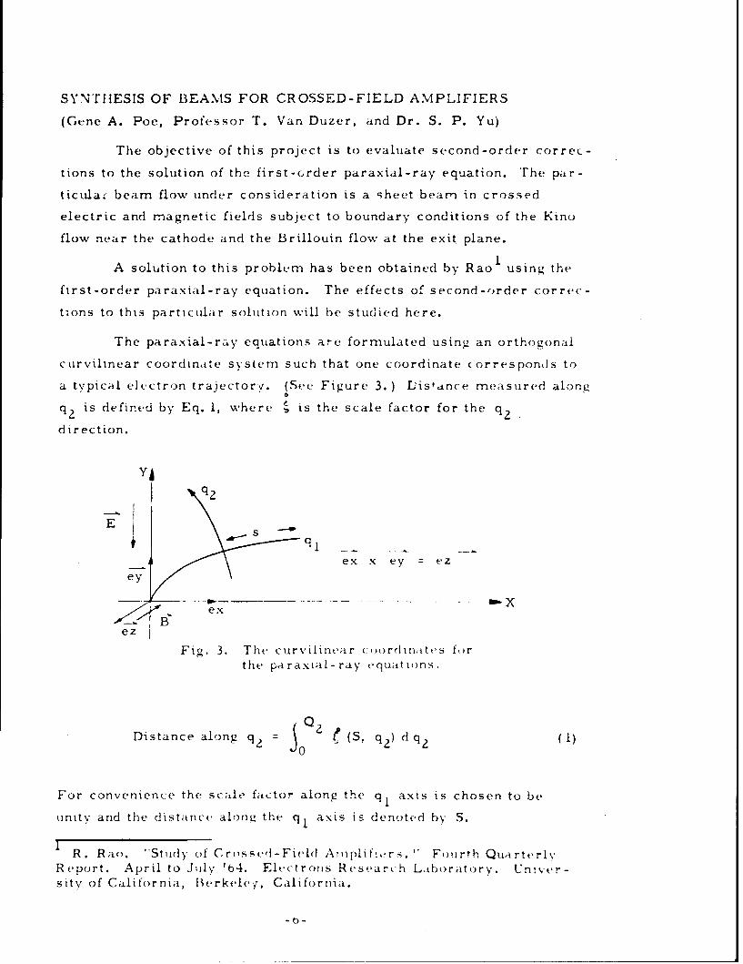
SYNTHESIS OF BEAMS FOR CROSSED-FIELD AMPLIFIERS
(Gene A. Poe, Professor T. Van Duzer, and Dr. S. P. Yu)
The objective of this project is to evaluate second-order correc-
tions to the solution of the first-order paraxial-ray equation. The par-
ticula. beam flow under consideration is a sheet beam in crossed
electric and magnetic fields subject to boundary conditions of the Kino
flow near the cathode and the Brillouin flow at the exit plane.
1A solution to this problem has been obtained by Rao using the
first-order paraxial-ray equation. The effects of second-order correc-
tions to this particular solution will be studied here.
The paraxial-ray equations are formulated using, an orthogonal
curvilinear coordinate systenm such that one coordinate corresponds to
a typical electron trajectory. (See Figure 3. ) L'istance measured alonga
Sis defined by Eq. 1, where i�s the scale factor for the q 2
direction.
YIE
q
S
ex
ez
Fig. 3. The curvilinear coordinattes f,)rthe paraxial-ray equatio)ns.
Distance along q2 = ý0Q2 e (S, q 2 ) d (q)
For convenience the scale factor along the q, axis is chosen to be
unity and the distance along the q, axis is denoted by S.
I R. Rao. "Study of Crossed-Field Arnplif:,,rs. " Fourth QuarterlyReport. April to July 'b4. Electrons Research Laboratory. UnIver-sity of California, IBerkele;, California.
-6-

It can be shown that this particular coordinate system lends it-
self to working only with scalar quantities and the three paraxial-ray
variables are potential, 0; curvature for the q, coordinate, k; and
the scale factor for the q 2 direction, i . Using a Taylor series expan-
sion for I about q 2 =0' the central trajectory, one obtains:
• o a j(s, q )i(S, q 2 ) 40(S, 0) + q2 qZ + (2)
q 2= 0
The paraxial formulations are found by taking only a few of the
terms in this series expansion. Keeping only the first term in Eq. 2,
one obtains the first-order paraxial-ray equation; and letting,
a Z(S, q2 ) ({(S, q 2 ) =(S, 0) + aq 2 q2
q 2 =0
one obtains a second-order paraxial-ray equation. For convenience,
one denotes j (S, 0) by 1, and by j . Higher-order paraxial-a 2 q 2 w0
ray equations can be found by adding more terms to Eq. 3.
The first-order paraxial-ray equation expressed in normalized
units can be written as follows:
2o E', + o' i1 + + 4k 2 0 + 1 + 2k7 ) 2 -0 (4)
The ;ocond-ordt.r paraxial-ray equation can also be expressed
in the same norrmalizcd units and is as follows:
-7-

4o 'k' + 86k"' '---- +~ V '.'
q 5+ 4o5k0"k i 20 zk' jT - q +~ 11220 9" 1 + 5
In Eqs. 4 and 5 the magnetic field is directed along the negative
z-direction and the prime superscripts denote differentiation with
respect to the arc length, 5, along q1 "
Using the solution given by Rao to the first-order paraxial-ray
equaiononesolves Eq. 5 for • the second-order scale factor; how-
ever, unlike the first-order ray equation, one must have values for the
first and second derivatives of the curvature, k, before the second-0
order equation can be solved for • q. Several methods of interpolating
and differentiating the curvature were studied and Newton's, Stirling's
and Bessel~s formulas were found to give very reliable results.
The second-order paraxial equation was solved on a computer2
(IBM 7094) using Gill's variation of the Runge-Kutta method. The
results obtained thus far are in the process of being checked by employ-
ing smaller interval sizes of integration in the computer program. The
curve in Fig. 4 shows the second-order scale factor plotted as a func-
tion of the arc length along q 1 "
2S. Gill. "A Process of Step-By-Step Integration of DifferentialEquations in an Automatic Digital Computing Machine. " Proc. Camb.Phil. Soc., 47. 1951, pp. 96- 108.
-8 -

-0.10
-0.05
0.0-10 20 30 40
+0.05 Fig. 4. Curve of eq plotted against arc
length along central trajectory.
The first and second-order half beam widths are defined as follows:
0
First-order half beam width L' (6)
Second-order half beam width L + .1 2qL,7
\2
where L is half the width of the cathode. Since the level lines of the
q,= constant are approximated by straight lines in the first-ordertheory and by circular arcs in the second-order theory, Eqs. 6 and 7
cannot be compared until they have been plotted on the q, and q.coordinate plane. This is being done and, at this point, it appears that
the second-order corrections to the first-order half beam width are
very small.
-9

FORWARD-WAVE NOISE-FIGURE STUDIES
(A. Sasaki, Professor T. Van Duzer, and Dr. S. P. Yu)
The aim of this work is to develop sufficient understanding of
the noise characteristics of forward-wave crossed-field amplifiers to
permit appreciable noise-figure reductions. The normal mode approach
will be used in the study of noise-transducing schemes.
By using normal mode amplitudes and coupled-mnode equations
we seek to derive an expression for the minimum noise figure of a
crossed-field amplifier. The kinetic power carried by the beam waves
in an O-type amplifier is described by
Re I;-l(U I wt R w, (1)
where • denotes the Hermitian conjugate, Re indicates the real part
of U I (the product of the kinetic potential and the ac current in theoUz z
beam direction),
wt [u ],(2)
and
01R (3)
However, in the case of a crossed-field amplifier, the kinetic power is
given by
Re= 1 + (I,(4)
2 L L TT
where b is the ac potential defined by the product of the ac displacement
and the dc electric field. Here, we use the coordinate system in which
one coordinate direction is along the beam path (indicated by the
-10-

subscript L), the other is the direction transverse to the beam path
(indicated by the subscript T), and the third is the direction perpendicu-
lar to the plane defined by T and L directions. This particular choice
of coordinates avoids the complexity of analysis for the accelerating
region where the electron beam is bending and makes the study of mini-
mum noise figure possible. We introduce the R and w matrices of the
crossed-field amplifier to express the kinetic power in the matrix form:
0 0 0 1
0 0 1 0
R 1 1 (5)
0 0kbS1 -•-•- b
o 1b
and
wt = [k I~ ~ (6)
where kb is the beam conductance of the electron beam in crossed
fields. The matrix form of the kinetic power is used for the minimum
noise-figure studies.
For the analysis of minimum noise figure.. we assume that the
region beyond the potential minimum in a crossed-field amplifier can
be represented by a linear, lossless transformation. Linearity follows
from the small signal assumption. However, the question might arise
whether the dioctron effect, by which ac currents grow in a drifting
region, prevents the drifting region from being represented by a loss-
less transducer. This question is resolved by w'iting the kinetic
power expression in terms of the normal mode amplitudes. The trans-
formation of noise fluctuations along the beam (magnitude of the
Fourier component of the noise fluctuations at angular frequency w) is
given by
-Il-

wb = Mw (7)
because the noise quantities at the position b are represented by a
linear combination of the noise quantities at the position a. Since the
region beyond the potential minimum is lossless, the kinetic power
must be conserved, which requires
w RW = w a Rw (8)b b a a
The use of Eqs. 7 in 8 gives us
Mt 1 RM R", (9)
which holds for any crossed-field amplifier. This matrix equation will
be used to find the invariant noise parameters in order to determine the
mininrum noise-figure. In the coming period, the minimum noise-
figure studies will be continued.
BACKWARD-WAVE NOISE-FIGURE STUDIES
(N. R. Mantena, Professor T. Van rDu7er, and Dr. S. P. Yu)
Noise figure calculations on the backward-wave amplifier have
been completed and are in excellent qualitative agreement with experi-
mental results. Quantitatively, the difference between theoretical and
experimental noise figures is found to be 6-7 db. This difference was
also found for the forward-wave amplifier. In these, as well as the
forward-wave calculations, it is iound that the position fluctuations
dominate over the other fluctuations. Space-charge reduction of noise
figure in backward-wave amplifiers is also explained by this theory.
Al3o, the noise-figure variation with beam current is in good qualita-
tive agreement with experiment.
We sought to explain the quantitative difference of 6-7 db between
Lhe theoretical and experimental noise figure by assuming a finite initial
correlation between the noise quantities at a plane slightly above the
-12-

potential minimum. H,,vever, even for hundred percent initial correla-
tion, the theoretical noise figure is changed only for a small fraction of
a decibel. Hence, the use of the experimental values of the noise-
figure in the noise-matrix inversion scheme results in unphysical
values for the noise quantities at the cathode.
Experiments with the modified long gun have bern completer4 .
It is found that the noise-figure incre,-ses with increased space-charge
loading for this gun configuration. The variation of noise-figure with
beam position is similar to that obtained for the Kino short gun and the
Charles gun. The measured noise-figure is several db larger than for
the Kino short gun.
A final report on this project will be completed during the next
quarter.
CATHODE-REGION STUDIES
(R. Y. C. Ho, Professor T. Van Duzer, and Dr. S. P. Yu)
The aim of this work is to study the effect of the crossed mag-
netic field on potential minimum stability. The method used in this
study is to form a relatively simple, space-charge feedback model for
calculating the shot noIse factor, r 2 = (I + , where i is thes /
emission perturbation current, and if is the feedback perturbation cur-
rent so as to explain the noise phenomena in crossed-field devices.
It is suspected that the potential minimum instability may be
closely connected with the termination of $3-electrons on the cathode.
The $3-electrons are defined as those electrons which pass through the
first critical planes. Since there are many classes of electrons in
$3-electron group, that is, for each pair of emission velocities there is
one critical plane, the half-Maxwellian initial velocity distribution in
the normal direction and full-Maxwellian initial velocity distribution in
the transverse direction are taken into account in the $3-electron ter-
mination feedback model. The $3-electron feedback is being modeled
as follows: (1) a d-c potential distribution which is uniform in the
-13-

transverse direction is assumed; (2) all the feedback currents are orig-
inated at the potential minimum, since the average position of the first
critical planes are always close to the potential minimum. A computer
program has been writen for this model, however, no calculations have
been made because the potential minimum parameters, Vm and Ymi
have nrt been specified, which, we believe, are important in forming
the complete feedback mode..
At present, a relatively simple approximate method is being
sought for determining the relation of V and Ym . The problem wasmm
first treated by determining the space charge density and solving the
Poisson's equation. The resulting analysis turried out to be complex.
A simpler model results if the beam current density is assumed to be
constant. However, this approach leads to a single equation relating
the ratio of beam current density to the emission current density, VM9
Y my and the magnetic field. Without a second equation the potential
minimum parameters V and Y cannot be determined separatelyr.• n m
Further attempts will be made to evaluate V and Y "
In the next period we will do the computer calculation of feed-
back model so as to determine the shot noise factor as a function of
crossed magnetic field.
CHARACTERISTICS OF THE SMOOTH-BORE MAGNETRON
1K. Mouthaa' and Professor C. Susskind)
This project was essentially completed during this quarter. A
final report entitled "Statistical theory of electron transport in crossed
fields" by K. Mouthaan has been submitted to AEL for approval.
Also completed during the past summer were the experiments
mentioned in the last report. These were conducted at Litton Industries
in San Carlos, California. The experimental configuration is shown in
Fig. 5. Experimental values of anode current were obtained for a range
of anode voltages at several values of magnetic field, for two values of
pressure. The experimental points follow the predicted dependence on
-14 -

~It
IS
000a
I
0,3 -6.74" 16.93"
DC/ 7,98"
Fig. 5. Configuration and dimensions of smooth-boremagnetron. Average anode diameter Da isequal to 6.93 - 3/16 in. Cathode-anode spacingd = (D/ - Da)/= 0.62 in.
/ 15
/ /-. -

(Va/B)3 extremely well; actual values obtained differ by a factor of
1/3.75 from those predicted on the basis of an ideal configuration, a
discrepancy ti at is doubtless accounted for by such factors as non-
uniformity of the beam in the axial directions, effective cathode emit-
ting area being smaller than total area, and misalignment (since cur-
rent density is inversely proportional to the fifth power of the cathode-
anode spacing).
The finding that the experimental anode current is indeeJ pro-
portional to (Va/B) 3 provides an important confirmaiion of the theory.
The proportionality is a direct consequence of the description of elec-
tron transport in the smooth-bore magnetron as diffusion, with the
diffusion coefficient proportional to the square of the impressed electric
field and inversely proportional to the cube of the magnetic field.
-16 -

ASSIF=EDSecurity Classification
DOCUMENT CONTROL DATA.- R&Dty classification of title, body of abetract and indeuin# annototfon rnuet be entered wheon the over*ll rePOrf te ItaeeIIIed)
IN G ACTIVITY (Corporate author) 2 PCPORT O f CU "TVC L.ASS.C A r1"ON
3nics Research Laboratory Ub £.ASZ`ZED
iity of California, Berkeley NZ
S...ITLE)F CROSSED-FIELD AMPLIFIEPS
"IVE NOTES (Typ of report and inclulive date*)
Zuarterly Progress Report - 16 June - 15 September 1965
) (Last name, ftret name. Initial)
A., Van Duzer, T., Yu, S. P., Poe, G. A., Sasaki, A., Mantena, N. R.,Y., Mouthaan, K., Susskind, C.
)ATI ?a TOTAL. TE OF PAGES 7b NO or irs16I 2
CT Of GRANT NO. So ORIGINAION'S REPORT NUMSER(S)
.039 AMC-O2164(E)No.13-0Ol
9b OTMER REPORT NO(S) (Arv other ntsbere fot may be aselfIteEhli report)
SILITY/LIMITATION NOTICES
'ied requesters may obtain copies of this report from DDC.'eport has been released to CFSTI.IIENTARY NOTES 12. SPONSORING MILITARY ACTIVITY
U. S. Army Electronics CommandFort Monmouth, New Jersey AMSEL-KL-_TM
T
,art of the project on the shield-gun low noise amplifier, a method ofizing crossed-field guns was developed and used to design an electron
t produces an electron beam having Kino flow characteristics near theand satisfying Brillouin flow conditions near the drift region.
ental results on the gun built on this basis show excellent agreementeoretical predictions. The second-order corrections to the solutionfi-st-order paraxial-ray equation used in the synthesis are discussed.
meal mode approach is usril to derive the invariant noise parameters of-field amplifiers with an objective to determine the minimum noise-
Results of the noise-figure studies based on the field approach ared with experiment. A simple approximate method to determine the dcal minimum parameters V and Y is proposed. The difficulty of deter-V and Y independently mis dis~issed. Important experimental results,ni a nov91 statistical theory of the smooth-bore magnetron, are alsod.
0.S1473 er ClassificatonSecurity Classification

Secwiaty Camificatic__LINK A LINX 9 LINK C
I[Y 111011O. W1 NOLZ Wo NOLS. WY
Crossed-Field AmplifiersCrossed-Field NoiseCathode-Region StudiesNoise-Figure of Crnssed-Field Amplifiers
Coupled-Mode Approach and Field ApproachMinimum Noise-Figure of Crossed-Field AmplifierPotentiaLl-Minimum InstabilitySmooth-Bore Magnet rons
IN'TRUCTIONS
1. ORIGINATING ACTIVITY: Enter the ntie and address imposed by security classification, using standard statementsof the comractor, subcontractor, pa eo, Department of D0- such as:fees. activity or other organisation (corporate author) issuing (1) "Qualified requesters may obtain copies of thisthe retor. report from DDC."
2& REPORT SECUWTY CLASIFICATION: Enter the over- (2) "Foreign announcement and dissemination of thisall security claseficatiotn of the report. Indicate whiether report by DDC is not authorised."Restricted Data" is included& Marking Is to be in accorpimnce with appropriate security rel,,atlons. (3) "U. S. Government agencia zey obtain copies ofthis report directly from DDC. Other qualified DOC
2b. GROUP: Automatic downgrading is specified in DoD Di- tsert dlrectl fro C tdrective 5200. 10 and Armed Forces Industrial ManuaL Enter users shall request tlwoughthe group number. Also, when applicable, show that optionalmarkings have been used for Group 3 and Group 4 as author- (4) "U. S. military agencies may obtain copies of thisised. report directly from DDC. Other qualified users
3.' REPORT TITLE: Enter the complete report title in all shall request through
capital letters. Titles in all cases should be unclassified.If a meaningful title carmot be selected without clasalfics"tion, show title classification in all capitals in parenthesis (3) "All distribution of this report is controlled. Qual.
immediately following the title. ified DDC users shall request through
4. DESCRIPTIVE NOTES: if appropriate, enter the type of ,_*
report. e.g., interim, progress, summery, annual, or final. If the report has been furnished to the Office of TechnicalGive the inclusive dates when a specific reporting period is Services, Deprtoent of Commerce, for sale to the public, indi-covered, cate this fact and enter the price, if known.
S. AUTHOR(S) Enter the name(s) of authors) as shown on IL SUPPLEMENTARY NOTES: Use for additional eaplmis.or in the report. Entet last name, first name, middle initial tory notes.If rilitary, show rank and branch of service. The name ofthe principal a.othor is an absolute minimum requirement. 12. SPONSORING MILITARY ACTIVITY: Enter the name of
the departmental project office or laboratory sponsoring (per. REPORT DATE. Enter the date of the report as day, ing for) the research and development. Include addr*ee.
month. year, or month, year. If more than one date appearson the report, use date of publication. 13 ABSTRACT: Enter an abstract giving a brief and factual
summary of the document indicative of the report, even though7& TOTAL NUMVBWR OF PAGES: The total page count It may also appear elsewhere in the body of the technical re-should follow normal pagination procedues, La., enter the port. If additional space in required, a continuation sheet shallnumber of pages containing informatior- be attached.
7b. NUMBER OF REFERENCES Enter the total number of It in highly desirable that the abstract of classified reportsre•ferences cited in the report. be unclassified. Each paregrerh of the abstract shall end with8a. CONTRACT OR GRANT NUMBER: If appropriate, enter an indication of the military seczrity classification of the in-
the applicable number of the contract or prant under which formation in the paragraph, represented as (TS). (s), (C). or (U).
the report was written. There is no limitation on the length of the abstract. flow-86, sk, & ad. PROJECT NUMBER: Enter the appropriate ever, the suggested length is frum 150 to 223 words.military department identification, such as project number,subproject number, system numbers. task number. etc. 14. KEY WORDS: Key words e technically meaoinltl terms
or short phrases that charecterise a report and &@y be used as9a. ORIGINATOR'S REPORT NUMBER(S): kAter t" roffl- index entries for cataloging the report. Key words must becial report number by which the document wUl be identified selected so that no security classification is required. Idoeti-and controlled by the originating activity. This number must fiels, such as equipment model designation, trade name, militarybe unique to this report, project code uame, geographic location, may be used as key
9b. OTHER REPORT NUMBER(S): If the report has been words but will be followed by an indication of technical coo-
assigned any other report numbers (either by the ortginoto, text. The assignment of links. #ales, and weights is optional.
or by the sponsor), also enter this number(s).
10. AVAILAABLITY/LIMITATION NOTICE& Enter any lim-Itations co further dissemination of the report, other than those
D D 'J 1473 (BACK) __C_;Security Classification