la rocca, a. and xu, z. and arumugam, p. and pickering, s.j....
TRANSCRIPT
La Rocca, A. and Xu, Z. and Arumugam, P. and Pickering, S.J. and Eastwick, Carol and Gerada, C. and Bozhko, S. (2016) Thermal management of a high speed permanent magnet machine for an aeroengine. In: XXIIth International Conference on Electrical Machines (ICEM '2016), 4-7 September 2016, Lausanne, Switzerland.
Access from the University of Nottingham repository: http://eprints.nottingham.ac.uk/34163/1/PID4153425%20%28002%29.pdf
Copyright and reuse:
The Nottingham ePrints service makes this work by researchers of the University of Nottingham available open access under the following conditions.
This article is made available under the University of Nottingham End User licence and may be reused according to the conditions of the licence. For more details see: http://eprints.nottingham.ac.uk/end_user_agreement.pdf
A note on versions:
The version presented here may differ from the published version or from the version of record. If you wish to cite this item you are advised to consult the publisher’s version. Please see the repository url above for details on accessing the published version and note that access may require a subscription.
For more information, please contact [email protected]

ΦAbstract -- The paper describes the mechanical and thermal design of a high speed, high power density synchronous permanent magnet machine for an aero engine starter generator system with a power rating of 150 kW and maximum speed of 32,000 rpm. As both mechanical and thermal aspects have a direct impact on machine overall performance and weight reduction, a critical design optimisation was carried out. Intensive cooling is guaranteed by direct liquid oil-cooling of stationary components; a stator sleeve is also introduced into the airgap to prevent excessive windage. Thermal investigations were carried out by the means of Computational Fluid Dynamics (CFD) and Lumped Parameter Thermal Network (LPTN) analyses. Experimental validation also allowed the identification of most critical machine temperatures and the validation of the models developed. Finite Element Analysis (FEA) is used for the static structural analyses of the stator sleeve.
Index Terms-- Aerospace Engineering, Cooling, Electric
machines, Generators, High Speed Machine, Mechanical Engineering, Permanent magnet motors, Thermal Management.
I. INTRODUCTION
HE electrical generator system is an important component in an aeroengine as it powers all the electrical equipment in the aircraft during flight and it,
operating as a motor, it can provide mechanical power to start the engine. Following the introduction of the aircraft design concept known as More Electric Aircraft [1], during last decades, electrical systems have gradually replaced non-propulsive aircraft systems such as mechanical, hydraulic, and pneumatic with electrically driven actuators.
The benefit of using electrical systems is the high efficiency achievable, usually above 90% [2]; this can lead to improve the overall aircraft performance, reducing the weight, reducing the fuel consumption and hence the emission of pollutants such as CO2. On the other side the on-board power demand has increased significantly since the 1990s; as an example the power demand on the Boeing aircraft has grown by the 300% from 0.25 MW of the
Φ This research is being conducted in the frame of AEGART Project (No.296090) – a Part of CleanSky JTI FP7 European Integrated Project.
A. La Rocca (e-mail: [email protected])1
Z. Xu, (e-mail:[email protected])1 P. Arumugam (e-mail: [email protected])2
S. J. Pickering (e-mail: [email protected])1 C. N. Eastwick (e-mail: [email protected])1 C.Gerada (e-mail: [email protected])2 S.Bozhko (e-mail: [email protected])2 1Department of Mechanical, Materials and Manufacturing Engineering,
The University of Nottingham, University Park, Nottingham, NG7 2RD, UK 2Department of Electrical and Electronic Engineering, The University of
Nottingham, University Park, Nottingham, NG7 2RD, UK
Boeing-777 to 1MW on the Boeing-787. This significant growth of the power demand makes the problem of the thermal management of the generators even more challenging as the amount of heat which must be removed can be considerable; as example assuming that each of the two generators in the Boeing 787 generates around 250 kW with an efficiency of 98%, the total losses which needs to be dissipated is 5 kW. For this reason the traditional cooling systems require to be improved in order to achieve effective cooling.
In this scenario the cooling of electrical machines becomes an aspect of primary importance in the machine design process; indeed effective thermal management does not simply keep temperatures down but has a direct impact on the reduction in the temperature dependent losses, increases the overall efficiency of the system, helps to reduce the amount of fuel required by the engine to drive the alternator and finally increases the lifetime of critical machine components such as windings and magnets [3].
Intensive cooling can only be achieved by employing liquid cooling options [4] however not all machine designs, especially those for high speed applications, are suitable for liquid cooling; for these reason alternative options need to be identified. In this work a direct oil cooling strategy is presented; analytical and numerical tools were used to investigate the thermal behaviour of the machine and to optimise the cooling design. Structural analyses were also carried out to analyse key components. Experimental validation also allowed to confirm the cooling capability of the design described and to validate the thermal models developed.
II. ELECTRICAL MACHINE DESIGN
The machine was designed to act as an aeroengine starter and generator feeding into a 270V DC supply with a nominal power of 150 kW. The machine runs as a motor during engine start and must supply constant torque from standstill to running speed after which the machine operates as a generator providing a maximum power of 150 kW at a maximum speed of 32,000 rpm as shown in Figure 1.
The key design requirements are high power to mass ratio and an efficiency of over 90%. By adopting a Surface mounted Permanent Magnet (SPM) machine as the favourite candidate design, different slot-pole combinations were investigated to minimize the overall drive system losses and weight while fulfilling the requirements both in engine start and generating modes. A 6-pole, 36-slot machine design was selected to achieve high performance, hence reduced losses. A Halbach array magnet structure is adopted to improve the air -gap flux density and a carbon fiber sleeve is used for
Thermal Management of a High Speed Permanent Magnet Machine for an Aeroengine
A. La Rocca, Z. Xu, P. Arumugam, S. J. Pickering, C. N. Eastwick, C. Gerada, S. Bozhko
T
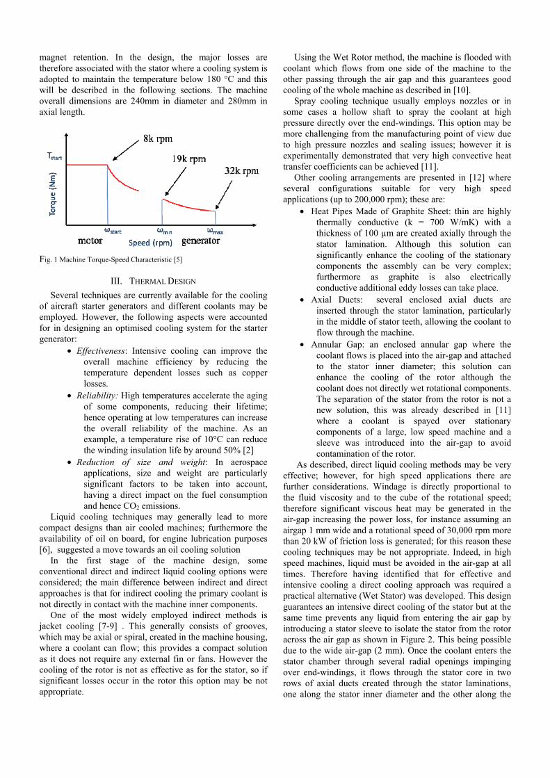
magnet retention. In the design, the major losses are therefore associated with the stator where a cooling system is adopted to maintain the temperature below 180 °C and this will be described in the following sections. The machine overall dimensions are 240mm in diameter and 280mm in axial length.
Fig. 1 Machine Torque-Speed Characteristic [5]
III. THERMAL DESIGN
Several techniques are currently available for the cooling of aircraft starter generators and different coolants may be employed. However, the following aspects were accounted for in designing an optimised cooling system for the starter generator:
• Effectiveness: Intensive cooling can improve the overall machine efficiency by reducing the temperature dependent losses such as copper losses.
• Reliability: High temperatures accelerate the aging of some components, reducing their lifetime; hence operating at low temperatures can increase the overall reliability of the machine. As an example, a temperature rise of 10°C can reduce the winding insulation life by around 50% [2]
• Reduction of size and weight: In aerospace applications, size and weight are particularly significant factors to be taken into account, having a direct impact on the fuel consumption and hence CO2 emissions.
Liquid cooling techniques may generally lead to more compact designs than air cooled machines; furthermore the availability of oil on board, for engine lubrication purposes [6], suggested a move towards an oil cooling solution
In the first stage of the machine design, some conventional direct and indirect liquid cooling options were considered; the main difference between indirect and direct approaches is that for indirect cooling the primary coolant is not directly in contact with the machine inner components.
One of the most widely employed indirect methods is jacket cooling [7-9] . This generally consists of grooves, which may be axial or spiral, created in the machine housing, where a coolant can flow; this provides a compact solution as it does not require any external fin or fans. However the cooling of the rotor is not as effective as for the stator, so if significant losses occur in the rotor this option may be not appropriate.
Using the Wet Rotor method, the machine is flooded with coolant which flows from one side of the machine to the other passing through the air gap and this guarantees good cooling of the whole machine as described in [10].
Spray cooling technique usually employs nozzles or in some cases a hollow shaft to spray the coolant at high pressure directly over the end-windings. This option may be more challenging from the manufacturing point of view due to high pressure nozzles and sealing issues; however it is experimentally demonstrated that very high convective heat transfer coefficients can be achieved [11].
Other cooling arrangements are presented in [12] where several configurations suitable for very high speed applications (up to 200,000 rpm); these are:
• Heat Pipes Made of Graphite Sheet: thin are highly thermally conductive (k = 700 W/mK) with a thickness of 100 µm are created axially through the stator lamination. Although this solution can significantly enhance the cooling of the stationary components the assembly can be very complex; furthermore as graphite is also electrically conductive additional eddy losses can take place.
• Axial Ducts: several enclosed axial ducts are inserted through the stator lamination, particularly in the middle of stator teeth, allowing the coolant to flow through the machine.
• Annular Gap: an enclosed annular gap where the coolant flows is placed into the air-gap and attached to the stator inner diameter; this solution can enhance the cooling of the rotor although the coolant does not directly wet rotational components. The separation of the stator from the rotor is not a new solution, this was already described in [11] where a coolant is spayed over stationary components of a large, low speed machine and a sleeve was introduced into the air-gap to avoid contamination of the rotor.
As described, direct liquid cooling methods may be very effective; however, for high speed applications there are further considerations. Windage is directly proportional to the fluid viscosity and to the cube of the rotational speed; therefore significant viscous heat may be generated in the air-gap increasing the power loss, for instance assuming an airgap 1 mm wide and a rotational speed of 30,000 rpm more than 20 kW of friction loss is generated; for this reason these cooling techniques may be not appropriate. Indeed, in high speed machines, liquid must be avoided in the air-gap at all times. Therefore having identified that for effective and intensive cooling a direct cooling approach was required a practical alternative (Wet Stator) was developed. This design guarantees an intensive direct cooling of the stator but at the same time prevents any liquid from entering the air gap by introducing a stator sleeve to isolate the stator from the rotor across the air gap as shown in Figure 2. This being possible due to the wide air-gap (2 mm). Once the coolant enters the stator chamber through several radial openings impinging over end-windings, it flows through the stator core in two rows of axial ducts created through the stator laminations, one along the stator inner diameter and the other along the

stator outer diameter as shown in Figure 3.
Fig. 2: Schematic Wet Stator [13]
Fig 3: Layout of axial ducts [13]
IV. THERMAL MODELLING
The thermal modelling of the machine was carried out by using both analytical (lumped parameter thermal network) and numerical (computational fluid-dynamics) approaches.
The commercial packages employed to analyse the thermal networks were MotorCAD and Simulink. MotorCAD, was used in the early stages of design process to investigate the thermal behaviour of initial machine designs and the performance of existing cooling strategies. A custom network of rotational components only was developed in Simulink and was mainly employed to investigate the heat transfer in bearing chambers.
However, the lumped parameter method is not fully capable of predicting all aspects of the fluid flow and the convective heat transfer phenomena; for this reason, some critical areas of the machine such as the end regions, the axial ducts and the airgap were investigated using CFD. By importing some numerical data into MotorCAD from the CFD models the thermal network could be improved.
A full 360° domain of the machine was modelled to perform steady-state conjugate heat transfer analysis. Due to the complexity of the real design several simplifications were made; these mainly consisted of the removal of small features such as screws, bolts and threads. Components such as coils, laminations and bearing chambers were modelled as bulk solids with overall thermal properties assigned. Figure 4 shows a cross-section of the domain created. Machine power losses, used as boundary conditions in the thermal models, are listed in Table I.
Fig 4: Cross-section of 3D Machine domain
TABLE I MACHINE POWER LOSSES AT 32,000 rpm
Source Power loss (W) Windings 1195 (at 180°C) Stator core 293 Bearings Non-Drive End 180 Bearing Drive End 100 Airgap (windage) 94 Magnets 51 Rotor core 9 Total 1,922
Some areas, such as end regions and the air-gap, were
separately investigated in order to have a better understanding of the fluid flow and to identify the optimal mesh densities to be used in the full model.
The Realizable k-epsilon, which is a Reynolds-Averaged Navier-Stokes based model (RANS), was the turbulence model used; this because the Realizable k-epsilon can generally provide better performance than the classic Standard k-epsilon for cases involving rotation and high shear stresses. The rotation is modelled using the Multiple Reference Frame (MRF) technique which is more suitable for steady-state cases and is less computationally demanding than the Sliding Mesh technique [23]. Enhanced wall treatment was used to resolve complex near wall phenomena which may occur; this implies an accurate sizing of the first layer of inflation in order to get the required y+ ~ 1.
V. MACHINE MECHANICAL DESIGN
Following the electrical, magnetic and thermal management studies of the machine, a semi-flooded machine with an oil sleeve between stator and rotor chambers was designed. The oil used to cool the machine also cools and lubricates bearings at both ends of the machine. This arrangement significantly simplifies the machine design. Figure 5 shows the overview of machine and the oil flow loops of machine cooling and bearing lubricant.

Fig 5: Overview of machine and cooling flow loops
Pressurized oil, at 4 bar, flows into the machine front flange via an oil inlet port. This separates into two streams within a manifold behind the front flange, 10% of the oil is used to lubricate the bearings at both ends of machine. The rest of the oil flows into an oil gallery- a donut shaped oil reservoir around the machine housing, shown in Figure 6.
High pressure oil is directly conducted to the bearing chambers and generates oil sprays impinging on the bearings at both ends of machine. The oil sprays in the bearing chambers lubricate the bearings and also remove heat generated by bearings. The oil-air mixture in the bearing chambers is sucked out and returns to the oil tank through an oil manifold, see Figure 5. Labyrinth seals are used to seal the bearing chambers and a lower pressure than ambient is maintained inside the bearing chambers to stop oil leaking to the rotor chamber.
The pressure and flow rate for machine cooling is controlled by an orifice within the inlet manifold before entry to the oil gallery. Evenly distributed circumferential holes are designed along the oil gallery, with oil from these holes impinging on the end windings and cooling the coil, see Figure 6. Also shown in Figure 6, is a deflection surface. Oil flows through channels between the stator core and housing is deflected by this surface to form a plane jet onto the end winding to cools these. The sizes, locations of oil jet and angle of the deflector face are optimized by CFD. A safety valve is designed within the inlet oil manifold to control the pressure inlet of the machine as can be seen in Figure 6. When the supplied oil pressure is too high, above 4 bar, the safety valve is opened and triggers an alarm.
Fig 6: Machine Cross-section view and detailed internal cooling flow path
The oil sleeve is one of the key components in this cooling design, see Figure 7. It separates the machine into two chambers: an oil flooded stator chamber and an oil free rotor chamber. This enables the machine to be well cooled
with low windage losses at high speed. The design of oil sleeve is important and ideally should
not be electrical conductive as it is placed in a rotating magnetic field. The sleeve should also be as thin as possible to reduce the air gap between the permanent magnets and stator laminate core. Both carbon fibre and glass fibre composite materials were considered, Figure 7. Finite Element Analysis (ANSYS), was used to check the linear buckling strength of the oil sleeve made by both carbon fibre (CF) and glass fibre (GF). A sleeve made of carbon fibre, 0.5mm thickness will be strong enough to bear the pressure in the stator chamber, but for a sleeve made of glass fibre, 1mm thickness should be used considering a safety factor of 1.5.
Fig 7: Oil sleeves made of carbon fibre and glass fibre.
Although the carbon sleeve is thinner than the glass fibre sleeve, considering the electrical conductivity of the material, a glass fibre sleeve is used for the final design.
VI. RESULTS AND EXPERIMENTAL VALIDATION
Throughout the design process the performance of the cooling system was evaluated by analysing and comparing the results obtained from the analytical and numerical thermal models developed.
Information regarding the machine temperatures distribution was used to establish whether the cooling strategy adopted was capable of letting the machine run safely when running at full power. Key machine components, such as windings and magnets, have to operate within acceptable temperature limits (220 °C and 200°C respectively).
Both the LPTN and CFD models developed provided detailed temperature distributions within the machine. Although the thermal network can only provide temperatures at a few locations compared to the numerical CFD model, key temperatures could still be identified.
The temperatures predicted show that in key machine components, such as windings and magnets the maximum difference is 5°C for the three analysis methods. Figure 8 shows the maximum temperature rise predicted in main machine components. As can be seen the most significant differences can be observed in end-windings and bearings where the discrepancy between the maximum temperatures

predicted is between 6% and 15%. The major limitation of the lumped parameters network is the modelling of the fluid flow; although some numerical data were implemented to overcome this deficiency the difference shown in end-winding temperatures highlights the issue. The significantly lower bearing temperatures predicted using the custom thermal network developed in Simulink can be attributed to the fact that the very detailed model can account for the heat dissipated into the oil.
Fig 8: Predicted maximum Temperature Rises at Full Power (32,000 rpm)
Figure 9 also shows the temperatures distribution within the machine; for better clarity only half of the machine is shown.
Fig 9: Temperatures distribution inside the machine
Validation of the machine thermal performance was investigated by carrying out a Short Circuit Test (SC Test) up to 12,000 rpm.
In order to evaluate the performance of the final design some measurements were taken; some in the middle of the coils inside the stator slots in order to identify the winding highest temperature and two in the inlet and outlet oil lines respectively. The oil flow rate was also measured. Measurements allowed the calculation of the oil temperature rise (ΔT) and the heat removed by the oil. All data presented refer to the steady state condition.
Machine losses, oil inlet temperature and oil flow rate were used as boundary conditions for the thermal models developed. A comparison between the maximum winding temperatures rise recorded experimentally and those obtained by modelling are shown in Figure 10.
Fig 10: Maximum Windings Temperature rise predicted and measured
VII. CONCLUSIONS
The work presented describes the cooling arrangement adopted for a high speed starter generator system for an aeroengine application. The key design feature is the glass fibre stator sleeve located in the airgap; this allows flooding the stationary components with liquid coolant but letting the rotating components run dry at all times, keeping windage manageable. The 1 mm stator sleeve is capable of withstanding up to 4 bar gauge according to the buckling analyses carried out. Several axial ducts created through the stator lamination let the coolant flow through the machine guaranteeing uniform cooling of all stationary components.
Analytical and numerical steady-state thermal analyses were performed for the thermal design of the machine at full power. Results obtained show that the strategy adopted is capable of maintaining temperatures well below the limits. Experimental data collected during initial tests carried out up to 12,000 rpm showed a good agreement with the predictions, as the difference achieved on the maximum temperatures reached in windings was within 3%.
VIII. ACKNOWLEDGEMENT
This research is being conducted in the frame of AEGART Project (No.296090) – a Part of CleanSky JTI FP7 European Integrated Project - http://www.cleansky.eu
IX. REFERENCES [1] Naayagi, R.T. A review of more electric aircraft technology. in Energy
Efficient Technologies for Sustainability (ICEETS), 2013 International Conference on. 2013.
[2] Pyrhonen, J., T. Jokinen, V. Hrabovcová, Design of Rotating Electrical Machines2008, Chichester, West Sussex, United Kingdom: Wiley.
[3] Stone G., C.I., Boulter E., Dhirani H., Electrical Insulation for Rotating Machines: Design, Evaluation, Aging, Testing, and Repair, 2nd Edition2014: Wiley-IEEE Press.
[4] Polikarpova, M., Liquid Cooling Solutions for Rotating Permanent Magnet Synchronous Machines, 2014, Lappeenranta University of Technology: Finland.
[5] Arumugam, P., Gerada, C., Bozhko, S., Zhang, H. et al.,, Permanent Magnet Starter-Generator for Aircraft Application, in SAE 2014 Aerospace Systems and Technology Conference2014: USA.
[6] Streifinger, H., Fuel/Oil System Thermal Management in Aircraft Turbine Engines, in Design Principles and Methods for Aircraft Gas Turbine Engines1998: Toulouse.
[7] Gerada, D., et al. Electrical machines for high speed applications with a wide constant-power region requirement. in Electrical Machines and Systems (ICEMS), 2011 International Conference on. 2011.
[8] Gerada, D., et al., Design Aspects of High-Speed High-Power-Density Laminated-Rotor Induction Machines. Industrial Electronics, IEEE Transactions on, 2011. 58(9): p. 4039-4047.
[9] Yu, W., et al. Research of novel water cooling jacket for explosion-proof motor. in Electrical Machines and Systems (ICEMS), 2013 International Conference on. 2013.
[10] Ponomarev, P., M. Polikarpova, and J. Pyrhonen. Thermal modeling of directly-oil-cooled permanent magnet synchronous machine. in Electrical Machines (ICEM), 2012 XXth International Conference on. 2012.
[11] Li, Z., et al. Study on spraying evaporative cooling technology for the large electrical machine. in Electrical Machines and Systems, 2009. ICEMS 2009. International Conference on. 2009.
[12] Tüysüz, A.S., M. Zwyssig, C. Kolar, J. Advanced Cooling Concepts for Ultra-High-Speed Machines. in Proceedings of the 9th International Conference on Power Electronics (ECCE Asia 2015). 2015. Seoul, South Korea: IEEE.
[13] Xu, Z., La Rocca, A., Pickering, S. J., Eastwick, C. N., Gerada, C., Bozhko, S., Mechanical and Thermal Design of an Aeroengine Starter/Generator in IEEE International Electric Machines and Drives Conference2015: USA.
X. BIOGRAPHIES
Antonino La Rocca obtained his PhD in Mechanical Engineering from the University of Nottingham, UK, in 2016; received his BEng and MEng in Mechanical Engineering from the University of Palermo in 2010 and 2011 respectively. He is currently working as researcher in the Fluids and Thermal Engineering research group. His research is mainly focused on fluid-dynamics, heat transfer and analytical and numerical thermal modelling of electrical machines.
Zeyuan Xu obtained his PhD in in Mechanical Engineering from the University of Manchester, UK, in 2002. He subsequently worked as a researcher at UMIST, Brunel University and University of Nottingham. His main research interests are in turbulent thermofluid flow, heat transfer enhancement, thermal management of advance electrical motor and power electronics, and mechanical design of high speed electrical machine.
Puvaneswaran Arumugam received the B.Eng. (Hons.) and Ph.D. degrees from the University of Nottingham, Nottingham, U.K., in 2009 and 2013, respectively. He is currently working as a researcher in the area of more electric aircraft propulsion and high performance electrical machines within the Power Electronics, Machines, and Control Group at the University of Nottingham, Nottingham, U.K. His main research interests are electrical machines and drives for more electric transportations, electro mechanical devices and systems, and analytical computation of electromagnetic fields. Stephen J. Pickering received the B.Sc. and Ph.D. degrees in mechanical engineering from the University of Nottingham, Nottingham, U.K., in 1979 and 1984, respectively. He joined the University of Nottingham as a lecturer in 1988, where he is currently Hives Professor of Mechanical Engineering in the Faculty of Engineering. He has extensive research experience in thermo-fluids and has undertaken research into the cooling of electric machines for over twenty years. Carol N. Eastwick received her BEng and PhD in Mechanical Engineering in 1990 and 1995 respectively. She is currently an Associate Professor in the Faculty of Engineering at the University of Nottingham, having worked on modelling and experimental investigations of thermofluids associated with rotating machinery for nearly twenty years. Chris Gerada obtained his PhD in Numerical Modelling of Electrical Machines from the University of Nottingham, England in 2005. He subsequently worked as a Researcher at The University of Nottingham, working on high performance electrical drives and on the design and modelling of electromagnetic actuators for aerospace applications, where he was appointed as a Lecturer in electrical machines in 2008, an Associate Professor in 2011, and a Professor in 2013. He has been the Project Manager of the GE Aviation Strategic Partnership since 2006. His core research interests include the design and modelling of high-performance electric drives and machines. Prof. Gerada was awarded a Royal Academy of Engineering Senior Research Fellowship supported by Cummins in 2011. He is an Associate Editor of the IEEE TRANSACTIONS ON INDUSTRY APPLICATIONS and an executive member of the management board of the
U.K. Magnetic Society and the IET Aerospace Technical and Professional Network. Serhiy Bozhko has received his MSc (1987) and PhD (1994) in electromechanical systems from the National Technical University of Ukraine. From 2000 he is with the Power Electronics, Machines and Controls Research Group in the University of Nottingham, United Kingdom in which he currently is in position of Associate Professor in Aircraft Electrical Systems. He is leading several EU- and industry funded projects in the area of aircraft electric power systems, including their control, power management, as well as advanced modelling and simulations methods.