lab 3 xbees and lcds and accelerometers, oh my!ese205/labs/ese205lab3revised.pdf · goal: - to...
TRANSCRIPT
University of Pennsylvania Department of Electrical and Systems Engineering
ESE 205: Intro to Circuit and Systems Lab
Last updated: September 25, 2012 by Nick Howarth, EE ‘13
Lab 3 – XBees and LCDs and Accelerometers, Oh My!
Introduction:
In the first part of this lab, you will learn how to use two XBee modules to transmit and receive
information wirelessly. XBee is a brand of low-power radio transmitter/receiver based on the
ZigBee digital communication protocol. First, you will program one Arduino board to transmit
one byte per second through an XBee module. The other Arduino will receive the byte through
an XBee module configured on the same channel as the transmitter, and it will turn a servo left
or right based on the identity of the byte. Next, you will use the XBee modules to remotely
control an LED on one Arduino with a photoresistor on another Arduino. This is similar to what
you did in the last part of Lab 1, except this time, it’s WIRELESS!
In the second part of this lab, you will learn how to use a LCD (liquid crystal display) screen for
text display and other interesting applications. You will first create a timer that shows a
countdown and sounds a buzzer after a certain amount of time has elapsed. You will then
change the pitch of a buzzer by tilting an accelerometer, while displaying the frequency of the
pitch on the LCD screen. Finally, you will use the accelerometer and LCD screen to simulate a
spirit-level indicator.
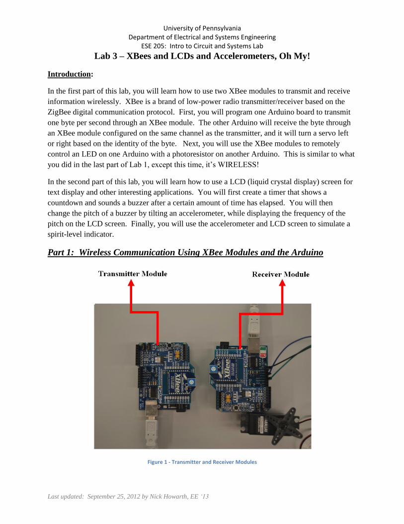
Part 1: Wireless Communication Using XBee Modules and the Arduino
Figure 1 - Transmitter and Receiver Modules
Goal:
- To control the motion of a continuous rotation Parallax motor using Arduino
communication via XBee.
- To control the lighting of an LED with a photoresistor using Arduino communication
via XBee.
Parts Required
1. 2 Arduino Boards
2. 2 USB Cables
3. 2 XBee Shields
4. 2 XBee Modules
5. 2 Extension Shields
6. Wires
7. Photoresistor
8. Two (2) 1 k resistors
9. LED
For this part of the lab, you will be paired up with another group since you must use two Arduino
boards. Your group will be assigned two XBee modules and two XBee Arduino shields. Each
pair of XBee modules is configured to communicate on a unique channel, so do not accidentally
switch one of your XBees with another group.
Remote control of a continuous rotation Parallax motor using XBee
Procedure:
One group (2 people) should set up the receiver (parts a through e) while the other group sets up
the transmitter (parts f through g).
Receiver Module
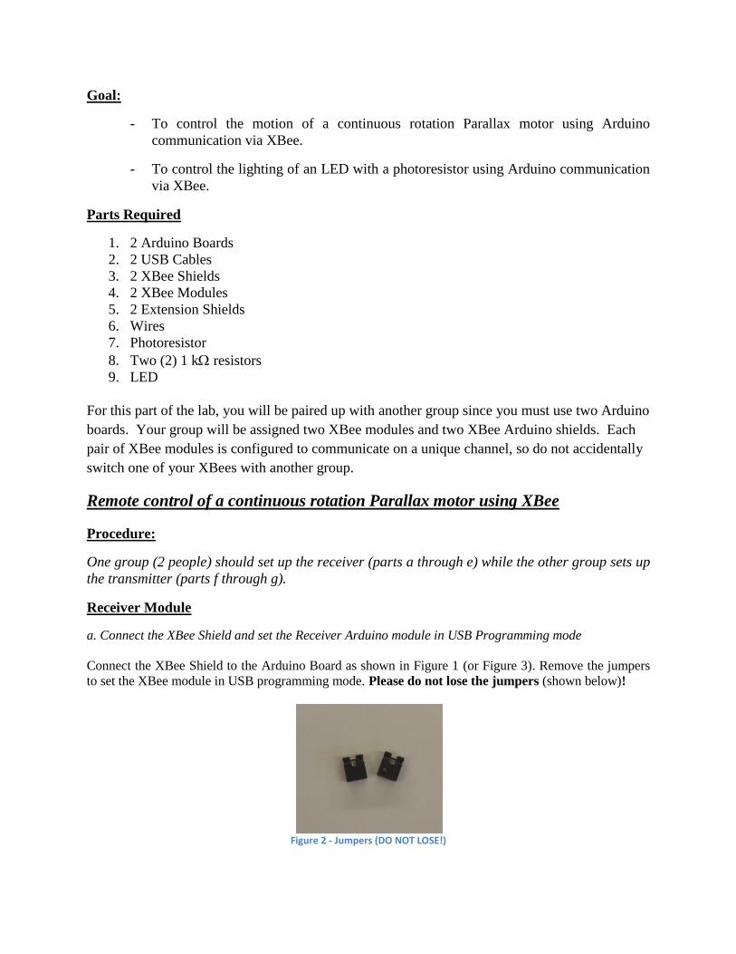
a. Connect the XBee Shield and set the Receiver Arduino module in USB Programming mode
Connect the XBee Shield to the Arduino Board as shown in Figure 1 (or Figure 3). Remove the jumpers
to set the XBee module in USB programming mode. Please do not lose the jumpers (shown below)!
Figure 2 - Jumpers (DO NOT LOSE!)
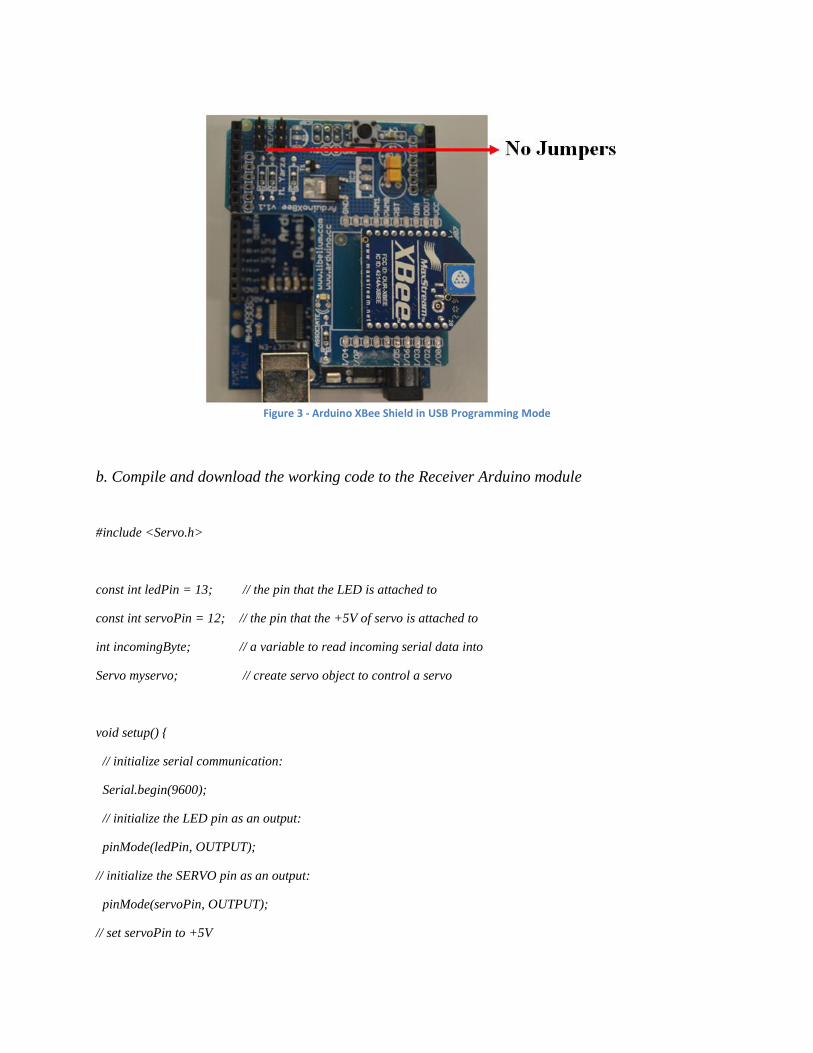
Figure 3 - Arduino XBee Shield in USB Programming Mode
b. Compile and download the working code to the Receiver Arduino module
#include <Servo.h>
const int ledPin = 13; // the pin that the LED is attached to
const int servoPin = 12; // the pin that the +5V of servo is attached to
int incomingByte; // a variable to read incoming serial data into
Servo myservo; // create servo object to control a servo
void setup() {
// initialize serial communication:
Serial.begin(9600);
// initialize the LED pin as an output:
pinMode(ledPin, OUTPUT);
// initialize the SERVO pin as an output:
pinMode(servoPin, OUTPUT);
// set servoPin to +5V

digitalWrite(servoPin, HIGH);
// Pin 10 of the Arduino output is connected to the PWN input of the servo motor
myservo.attach(10);
}
void loop() {
// see if there's incoming serial data:
if (Serial.available() > 0) {
// read the oldest byte in the serial buffer:
incomingByte = Serial.read();
// if it's a capital L (ASCII 72), turn on the LED and rotate the servo motor clockwise
if (incomingByte == 'L') {
digitalWrite(ledPin, HIGH);
myservo.write(0);
}
// if it's an R (ASCII 76) turn off the LED and rotate the servo motor anti-clockwise
if (incomingByte == 'R') {
digitalWrite(ledPin, LOW);
myservo.write(180);
}
}
}
d. Set the Receiver Arduino module in XBee mode
Connect the jumpers to the XBee shield, as shown in Figure 4, to set it on XBee mode. This will be the
receiver Arduino module.

Figure 4 - Arduino XBee Shield in XBee Mode
e. Connect one of the Boe-Bot’s servos to the receiver Arduino module as shown in Figure 5.
Figure 5 - Continuous Rotation Parallax Motor
Note: You are using one of the servos on your Boe-Bot platform, not the servo pictured above.
Transmitter Module
f. Follow step ‘a’ to set the Transmitter Arduino module in USB Programming mode
g. Compile and download the working code to the Transmitter Arduino module

void setup()
{
Serial.begin(9600); // initialize serial communication
}
void loop()
{
Serial.print('L');
delay(1000);
Serial.print('R');
delay(1000);
}
h. Set the Transmitter Arduino module in XBee mode as in step ‘d’, by connecting the jumper
wires
i. Observe the rotation of the servo motor
In the Arduino window containing the code for the transmitter, open the serial monitor by
pressing the “Serial Monitor” button to the right of the “Upload” button. You should see
alternating L’s and R’s appear every second. The servo motor attached to the receiver module
will turn clockwise and anticlockwise based on the serial data transmitted from the transmitter
module. The LED on the receiver module should blink on and off.
Remote control of an LED using a photoresistor circuit and XBee
Procedure:
The group (2 people) that set up the receiver in the previous part should now set up the
transmitter, and the group that set up the transmitter last time should set up the receiver.
This part requires you to construct a circuit on both the receiving and transmitting Arduino
boards. However, there is no room to fit a breadboard on the Arduino since it is occupied by the
XBee shield. For this reason, we have constructed extension shields that can hold a breadboard
shield, XBee shield, and LCD screen all on one shield. The only limitation is that each
component occupies a number of digital I/O pins; consequently, only two components can be
used at a time. In this part of the lab, you will use the extension shield to hold the XBee shield
and the breadboard shield.
Connect your shields as shown in Figure 6.

Figure 6 - Configuration of Arduino Shields on Extension Shield
Receiver Module
a. Construct the circuit given by the schematic in Figure 7.
Figure 7 - Receiver LED circuit
b. Set the Arduino in USB Programming mode (remove jumpers) and copy the following code into
your window.
const int ledPin = 12; // the pin that the LED is attached to
int incomingByte; // a variable to read incoming serial data into
void setup() {
Serial.begin(9600); // initialize serial communication
pinMode(ledPin, OUTPUT); // initialize the LED pin as an output
}
void loop() {
// see if there's incoming serial data:
if (Serial.available() > 0){
Transmitter Receiver

// read the oldest value in the serial buffer:
incomingByte = Serial.read();
if(incomingByte == 'D'){
digitalWrite(ledPin, HIGH);
}
else if(incomingByte == 'L'){
digitalWrite(ledPin, LOW);
}
}
}
c. Finish writing the code above. Hint: you did this at the end of Lab 1!
d. Set the Arduino in XBee mode by connecting the jumpers.
Transmitter Module
e. Construct the circuit given by the schematic in Figure 8. Choose any analog pin (0-5).
Figure 8 - Transmitter voltage divider circuit
f. Set the Arduino in USB Programming mode (remove jumpers) and upload the following code:
int analogPin = ***; // change *** to the pin number you're reading from
int value;
void setup(){
Serial.begin(9600); // initialize serial communication
//pinMode(analogPin, INPUT);
}
void loop(){
value = analogRead(analogPin);
if(value >= 150){ // you may need to modify this argument
Serial.print('L');
delay(500);
}
if(value < 150){
Serial.print('D');
delay(500);
}
}
g. Set the Transmitter Arduino in XBee mode by connecting the jumpers.
h. Demonstrate to a TA that your system works!
Thinking Further – Biomedical application
With technology rapidly evolving, it is becoming possible for medical professionals to remotely
observe and treat patients. This new form of medicine, called telemedicine, allows people in
need of medical surveillance to move around comfortably at home while their physiological
signals, such as heart rate, brain and muscle activity, etc., are wirelessly transmitted to a
computer and sent to a medical center to be analyzed.
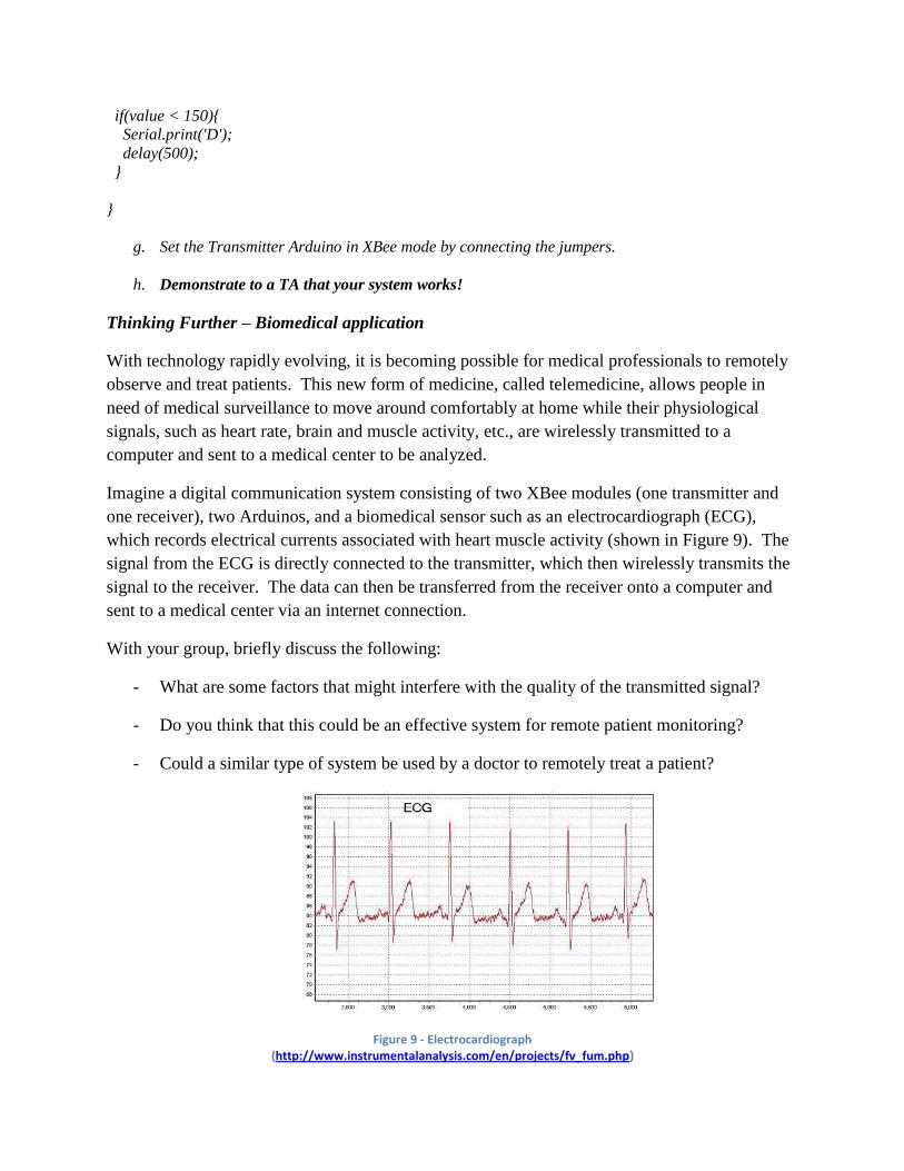
Imagine a digital communication system consisting of two XBee modules (one transmitter and
one receiver), two Arduinos, and a biomedical sensor such as an electrocardiograph (ECG),
which records electrical currents associated with heart muscle activity (shown in Figure 9). The
signal from the ECG is directly connected to the transmitter, which then wirelessly transmits the
signal to the receiver. The data can then be transferred from the receiver onto a computer and
sent to a medical center via an internet connection.
With your group, briefly discuss the following:
- What are some factors that might interfere with the quality of the transmitted signal?
- Do you think that this could be an effective system for remote patient monitoring?
- Could a similar type of system be used by a doctor to remotely treat a patient?
Figure 9 - Electrocardiograph (http://www.instrumentalanalysis.com/en/projects/fv_fum.php)

Part 2: Applications of LCD Screen and Accelerometer
Parts Required:
1. Arduino Board
2. USB Cable
3. Sound Buzzer
4. 16X2 LCD Display
5. ADXL335, 3-axis Accelerometer
6. Wires
Self-Timer using the Arduino
Procedure:
a. Building the circuit
Attach the LCD screen shield to the Arduino, and place the breadboard shield on top, as shown
in Figure 10. Build the sound buzzer circuit as described in Figure 11.
Figure 10 - Arduino Shield Configuration
Figure 11 - Sound Buzzer Circuit
6
b. Compile and download the following working code to the Arduino Board using Arduino IDE.
#include <LiquidCrystal.h>
// initialize the library with the numbers of the interface pins
LiquidCrystal lcd(12, 11, 13, 10, 9, 8);
int runTimer = 1; // true condition for timer
int serialData = 0; // false condition for serial communication
int speakerPin = 6;
int data = 0; // default condition
void setup() {
pinMode(speakerPin, OUTPUT);
// set up the LCD's number of rows and columns:
lcd.begin(16, 2);
}
void loop() {
// To execute timer only once
if(runTimer == 1){
// Print a message to the LCD.
lcd.clear();
lcd.print("Timer: ");
//Start timer
timer(); // runs the timer code below, under void timer()
}
runTimer = 0;
lcd.noDisplay();
delay(250);
// Sound Buzzer
for(int duration = 0; duration < 100; duration ++){
digitalWrite(speakerPin, HIGH);

delayMicroseconds(2000);
digitalWrite(speakerPin, LOW);
delayMicroseconds(2000);
}
lcd.display();
delay(250);
}
void timer(){
// For loop to run the COUNT-DOWN in Seconds
for(int timer = 10; timer > 0; --timer){
// Set the Cursor to the space after the display "TIMER: "
if(timer >= 10)
lcd.setCursor(6,0);
else{
lcd.setCursor(6,0);
lcd.print("0");
lcd.setCursor(7,0);
}
// Display the COUNT-DOWN Seconds
lcd.print(timer);
lcd.print("s");
delay(1000);
}
// Bring the Cursor to the initial position
lcd.setCursor(0,0);
lcd.clear();
lcd.print("Buzzer!");
}

c. Self-Timer and Sound Buzzer
Press the RESET Button of the Arduino board, the timer will countdown from 10 seconds, as
programmed. Once the timer countdown reaches 0s, the buzzer will go on and the LCD display
will blink “Buzzer!”
The program is reset every time you press the RESET Button of the Arduino board and the timer
countdown begins again.
d. Questions
i. Can you make the timer countdown from 100 seconds?
ii. Can you make the buzzer buzz only for a fixed amount of time after the timer countdown
reaches 0s? Show a TA!
Possibly helpful reference links:
http://arduino.cc/en/Reference/For
http://arduino.cc/en/Reference/While
Pitch-Control Using an Accelerometer and the Arduino
Procedure:
a. 3-Axis Accelerometer
An accelerometer is used to measure the acceleration experienced by an object. The ADXL335
(two versions shown in Figure 12) is adopted to measure the acceleration experienced by the
object in motion with respect to the X or Y or Z axis. We will only be measuring movements to
the Y axis in this lab.
Figure 12 – Two versions of the ADXL335, 3-axis Accelerometer
b. Interface the 3-Axis Accelerometer
Connect the 3-Axis accelerometer to the Arduino shield as shown in Figure 13. Keep your
buzzer circuit from the previous part connected.

Figure 13 – Interfacing ADXL335, 3-Axis Accelerometer, with the Arduino Board
c. Copy the following code into the Arduino IDE.
The code below will work correctly for the red Sparkfun accelerometers connected as
shown in Figure 13. If you are using a blue or green ADXL335, you must make sure the
groundpin, powerpin, and ypin values match the corresponding pins on the accelerometer.
Note that analog I/O pins 0-5 are referred to as pins 14-19 (to distinguish them from the
digital I/O pins).
#include <LiquidCrystal.h>
// initialize the library with the numbers of the interface pins
LiquidCrystal lcd(12, 11, 13, 10, 9, 8);
const int groundpin = 18; // analog input pin4 -- ground
const int powerpin = 19; // analog input pin5 -- voltage (Vcc)
const int ypin = 16; // analog input pin3 -- y-axis pin
const int buzzerPin = 6; // digital input pin6 -- buzzer
int yvalue;
int freq;
int ymin = 0; // Replace with measured minimum yvalue
int ymax = 1; // Replace with measured maximum yvalue
void setup() {
pinMode(ypin, INPUT);

pinMode(buzzerPin, OUTPUT);
pinMode(groundpin, OUTPUT);
pinMode(powerpin, OUTPUT);
digitalWrite(groundpin, LOW); // make analog pin (4) equivalent to ground
digitalWrite(powerpin, HIGH); // make analog pin (5) equivalent to Vcc (voltage source)
// set up the LCD's number of rows and columns:
lcd.begin(16, 2);
}
void loop() {
yvalue = analogRead(ypin);
freq = map(yvalue, ymin, ymax, 100, 10000); // maps yvalue into frequency range
tone(buzzerPin, freq); // sounds buzzer at given frequency
lcd.clear();
lcd.setCursor(0,0);
lcd.print("Freq: ");
lcd.print(freq);
lcd.print(" Hz");
lcd.setCursor(0,1);
lcd.print("yvalue: ");
lcd.print(yvalue);
delay(150);
}
d. Find the range of the y-axis acceleration
Find the minimum and maximum values of the y-axis acceleration (yvalue). Replace the values
of ymin and ymax with the values you found. Upload the code to the Arduino and tilt the board
along the y-axis to observe its effect.
The map function map(value, fromLow, fromHigh, toLow, toHigh) maps a value of
fromLow to toLow, a value of fromHigh to toHigh, values in-between to values in-
between, etc. In this case, yvalue is converted from an acceleration value to a frequency value.
To get more information about any function, right-click the function name and click “Find in
Reference.”

e. Questions
i. If yvalue is 450, then what is the value of freq?
ii. How would you change the range of frequencies that is swept through?
iii. Can you modify the code so that change of pitch sounds more continuous?
iv. Change the code so that the change in frequency correlates with acceleration on the x-
axis instead of the y-axis? Show a TA!
Spirit-Level Indicator using the Arduino
Procedure:
a. Compile and upload the working code to the Arduino Board.
#include <LiquidCrystal.h>
LiquidCrystal lcd(12, 11, 13, 10, 9, 8);
const int groundpin = 14; // analog input pin0 -- ground
const int powerpin = 18; // analog input pin4 -- voltage
const int ypin =2; // y-axis of the accelerometer
void setup() {
lcd.begin(16, 2);
Serial.begin(9600);
pinMode(groundpin, OUTPUT);
pinMode(powerpin, OUTPUT);
digitalWrite(groundpin, LOW);
digitalWrite(powerpin, HIGH);
}
void loop() {
int avalue = 0;
int lcd_Cursor_Position = 0;
lcd.clear();
avalue = analogRead(ypin); // read value of the X-axis acceleration
lcd_Cursor_Position = 46 - avalue/13; // calculation to position the lcd cursor
Serial.print(avalue); // prints x-axis acceleration in serial monitor
lcd.setCursor((15 - lcd_Cursor_Position), 1);

lcd.print('.');
lcd.setCursor((15 - lcd_Cursor_Position), 0);
lcd.print('.');
delay(100);
}
b. Questions:
v. Can you display the spirit level using other characters apart from ‘.’?
vi. Can you make the spirit level indicator ‘.’ move in the direction of the acceleration?
vii. Can you make one spirit level indicator ‘.’ move in opposite direction to the other?
viii. Extra Credit: Using a sound buzzer, play any musical note, if the level indicator is
stationary in a particular position for more than 10 seconds. Show a TA!