lab 9.2.5 vtp client and server configurations – 2924xl...
TRANSCRIPT
533 - 577 CCNA 3: Switching Basics and Intermediate Routing v 3.1 - Lab 9.2.5 Copyright 2003, Cisco Systems, Inc.
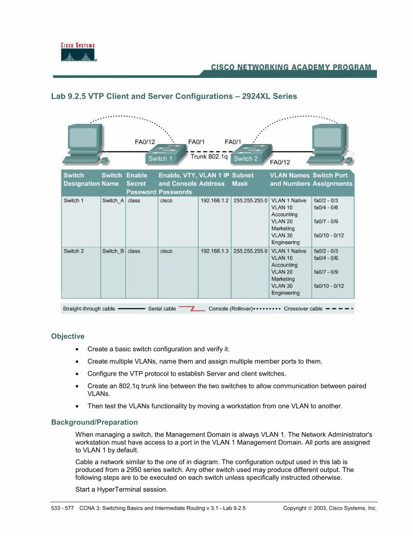
Lab 9.2.5 VTP Client and Server Configurations – 2924XL Series
Objective • Create a basic switch configuration and verify it.
• Create multiple VLANs, name them and assign multiple member ports to them.
• Configure the VTP protocol to establish Server and client switches.
• Create an 802.1q trunk line between the two switches to allow communication between paired VLANs.
• Then test the VLANs functionality by moving a workstation from one VLAN to another.
Background/Preparation When managing a switch, the Management Domain is always VLAN 1. The Network Administrator's workstation must have access to a port in the VLAN 1 Management Domain. All ports are assigned to VLAN 1 by default.
Cable a network similar to the one of in diagram. The configuration output used in this lab is produced from a 2950 series switch. Any other switch used may produce different output. The following steps are to be executed on each switch unless specifically instructed otherwise.
Start a HyperTerminal session.
534 - 577 CCNA 3: Switching Basics and Intermediate Routing v 3.1 - Lab 9.2.5 Copyright 2003, Cisco Systems, Inc.
Note: Go to the erase and reload instructions at the end of this lab. Perform those steps on all switches in this lab assignment before continuing.
Step 1 Configure the switch Configure the hostname, access, and command mode passwords, as well as the management LAN settings. These values are shown in the chart. If problems occur while performing this configuration, refer to the Basic Switch Configuration lab.
Step 2 Configure the hosts attached to the switch Configure the IP address, mask, and default gateway on each host. Be sure to choose addresses that are on the same subnet as the switch.
Step 3 Verify connectivity a. To verify that the host and switch are correctly configured, ping the switch from the hosts.
b. Were the pings successful? Yes
c. If the answer is no, troubleshoot the host and switches configurations.
Step 4 Display the VLAN interface information On Switch_A, type the command show vlan at the Privileged EXEC prompt as follows:
Switch_A#show vlan
Note: There should be an entry for VLAN 1 and the default VLANs (1002 +). If other VLANs appear, they could be deleted as instructed in Step 2 of the Erasing and Reloading instructions at the end of this lab or refer to the Lab Exercise: Deleting VLAN Configurations.
Step 5 Configure VTP a. VLAN Trunking Protocol (VTP) needs to be configured on both switches. VTP is the protocol that
will communicate information about which VLANs exist from one switch to another. If VTP did not provide this information, VLANs would have to be created on all switches individually.
b. By default, the Catalyst switch series are configured as VTP servers. In the event that the server services are turned off, use the following command to turn it back on:
Switch_A#vlan database Switch_A(vlan)#vtp server Switch_A(vlan)#vtp domain group1 Switch_A(vlan)#exit
Step 6 Create and name three VLANs Enter the following commands to create and name three VLANs:
Switch_A#vlan database Switch_A(vlan)#vlan 10 name Accounting Switch_A(vlan)#vlan 20 name Marketing Switch_A(vlan)#vlan 30 name Engineering Switch_A(vlan)#exit
Use the show vlan command to verify that the VLANs have been created correctly.
535 - 577 CCNA 3: Switching Basics and Intermediate Routing v 3.1 - Lab 9.2.5 Copyright 2003, Cisco Systems, Inc.
Step 7 Assign ports to VLAN 10 Assigning ports to VLANs must be done from the interface mode. Enter the following commands to add ports 0/4 to 0/6 to VLAN 10:
Switch_A#configure terminal Switch_A(config)#interface fastethernet 0/4 Switch_A(config-if)#switchport mode access Switch_A(config-if)#switchport access vlan 10 Switch_A(config-if)#interface fastethernet 0/5 Switch_A(config-if)#switchport mode access Switch_A(config-if)#switchport access vlan 10 Switch_A(config-if)#interface fastethernet 0/6 Switch_A(config-if)#switchport mode access Switch_A(config-if)#switchport access vlan 10 Switch_A(config-if)#end
Step 8 Assign ports to VLAN 20 Enter the following commands to add ports 0/7 to 0/9 to VLAN 20:
Switch_A#configure terminal Switch_A(config)#interface fastethernet 0/7 Switch_A(config-if)#switchport mode access Switch_A(config-if)#switchport access vlan 20 Switch_A(config-if)#interface fastethernet 0/8 Switch_A(config-if)#switchport mode access Switch_A(config-if)#switchport access vlan 20 Switch_A(config-if)#interface fastethernet 0/9 Switch_A(config-if)#switchport mode access Switch_A(config-if)#switchport access vlan 20 Switch_A(config-if)#end
Step 9 Assign ports to VLAN 30 Enter the following commands to add ports 0/10 to 0/12 to VLAN 30:
Switch_A#configure terminal Switch_A(config)#interface fastethernet 0/10 Switch_A(config-if)#switchport mode access Switch_A(config-if)#switchport access vlan 30 Switch_A(config-if)#interface fastethernet 0/11 Switch_A(config-if)#switchport mode access Switch_A(config-if)#switchport access vlan 30 Switch_A(config-if)#interface fastethernet 0/12 Switch_A(config-if)#switchport mode access Switch_A(config-if)#switchport access vlan 30 Switch_A(config-if)#end
Step 10 Display the VLAN interface information a. On Switch_A, type the command show vlan at the Privileged EXEC prompt as follows:
Switch_A#show vlan
536 - 577 CCNA 3: Switching Basics and Intermediate Routing v 3.1 - Lab 9.2.5 Copyright 2003, Cisco Systems, Inc.
b. Are ports 0/10 through 0/12 assigned to VLAN 30? Yes
Step 11 Configure VTP client Enter the following commands to configure Switch_B to be a VTP client:
Switch_B#vlan database Switch_B(vlan)#vtp client Switch_B(vlan)#vtp domain group1 Switch_B(vlan)#exit
Step 12 Create the trunk On both switches, Switch_A and Switch_B, type the following command at the fastethernet 0/1 interface command prompt. Note that it is not necessary to specify the encapsulation on a 2950, since it only supports 802.1Q.
Switch_A(config)#interface fastethernet 0/1 Switch_A(config-if)#switchport mode trunk Switch_A(config-if)#end Switch_B(config)#interface fastethernet 0/1 Switch_B(config-if)#switchport mode trunk Switch_B(config-if)#end
2900:Note that it is necessary to specify the encapsulation on a 2924XL, since it supports 802.1Q and ISL.
Switch_A(config)#interface fastethernet0/1 Switch_A(config-if)#switchport mode trunk Switch_A(config-if)#switchport trunk encapsulation dot1q Switch_A(config-if)#end Switch_B(config)#interface fastethernet0/1 Switch_B(config-if)#switchport mode trunk Switch_B(config-if)#switchport trunk encapsulation dot1q Switch_B(config-if)#end
Step 13 Verify the trunk a. To verify that port fastethernet 0/1 has been established as a trunk port, type show interface
fastethernet 0/1 switchport at the Privileged EXEC mode prompt
b. What type of trunking encapsulation is shown on the output results? Dot1q
Step 14 Display the VLAN interface information a. On Switch_B, type the command show vlan at the Privileged EXEC prompt as follows:
Switch_B#show vlan
b. Do VLANs 10, 20, and 30 show without having to type them in? Yes
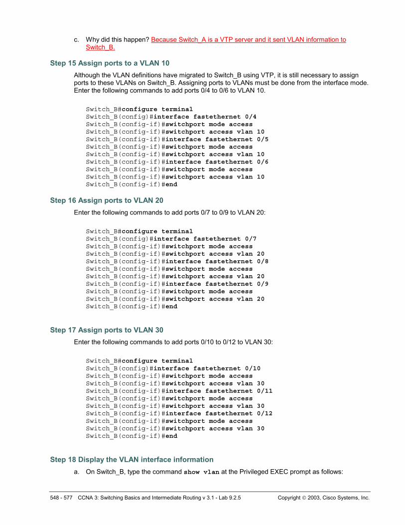
c. Why did this happen? Because Switch_A is a VTP server and it sent VLAN information to Switch_B
537 - 577 CCNA 3: Switching Basics and Intermediate Routing v 3.1 - Lab 9.2.5 Copyright 2003, Cisco Systems, Inc.
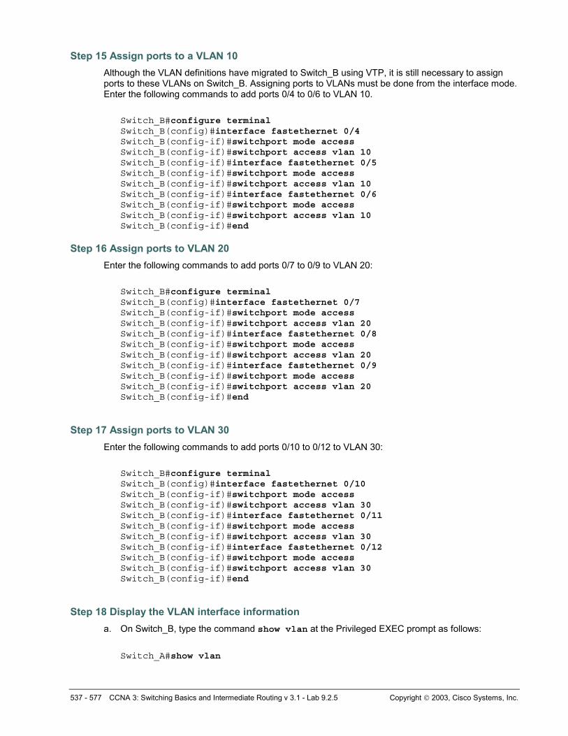
Step 15 Assign ports to a VLAN 10 Although the VLAN definitions have migrated to Switch_B using VTP, it is still necessary to assign ports to these VLANs on Switch_B. Assigning ports to VLANs must be done from the interface mode. Enter the following commands to add ports 0/4 to 0/6 to VLAN 10.
Switch_B#configure terminal Switch_B(config)#interface fastethernet 0/4 Switch_B(config-if)#switchport mode access Switch_B(config-if)#switchport access vlan 10 Switch_B(config-if)#interface fastethernet 0/5 Switch_B(config-if)#switchport mode access Switch_B(config-if)#switchport access vlan 10 Switch_B(config-if)#interface fastethernet 0/6 Switch_B(config-if)#switchport mode access Switch_B(config-if)#switchport access vlan 10 Switch_B(config-if)#end
Step 16 Assign ports to VLAN 20 Enter the following commands to add ports 0/7 to 0/9 to VLAN 20:
Switch_B#configure terminal Switch_B(config)#interface fastethernet 0/7 Switch_B(config-if)#switchport mode access Switch_B(config-if)#switchport access vlan 20 Switch_B(config-if)#interface fastethernet 0/8 Switch_B(config-if)#switchport mode access Switch_B(config-if)#switchport access vlan 20 Switch_B(config-if)#interface fastethernet 0/9 Switch_B(config-if)#switchport mode access Switch_B(config-if)#switchport access vlan 20 Switch_B(config-if)#end
Step 17 Assign ports to VLAN 30 Enter the following commands to add ports 0/10 to 0/12 to VLAN 30:
Switch_B#configure terminal Switch_B(config)#interface fastethernet 0/10 Switch_B(config-if)#switchport mode access Switch_B(config-if)#switchport access vlan 30 Switch_B(config-if)#interface fastethernet 0/11 Switch_B(config-if)#switchport mode access Switch_B(config-if)#switchport access vlan 30 Switch_B(config-if)#interface fastethernet 0/12 Switch_B(config-if)#switchport mode access Switch_B(config-if)#switchport access vlan 30 Switch_B(config-if)#end
Step 18 Display the VLAN interface information a. On Switch_B, type the command show vlan at the Privileged EXEC prompt as follows:
Switch_A#show vlan
538 - 577 CCNA 3: Switching Basics and Intermediate Routing v 3.1 - Lab 9.2.5 Copyright 2003, Cisco Systems, Inc.
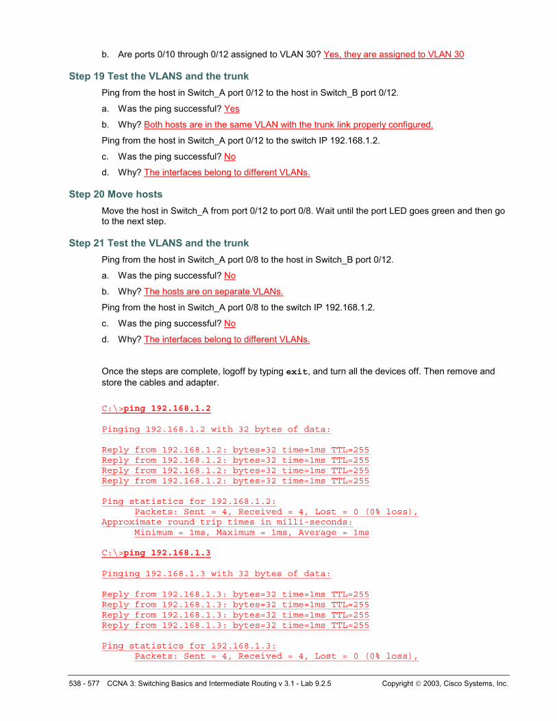
b. Are ports 0/10 through 0/12 assigned to VLAN 30? Yes, they are assigned to VLAN 30
Step 19 Test the VLANS and the trunk Ping from the host in Switch_A port 0/12 to the host in Switch_B port 0/12.
a. Was the ping successful? Yes
b. Why? Both hosts are in the same VLAN with the trunk link properly configured.
Ping from the host in Switch_A port 0/12 to the switch IP 192.168.1.2.
c. Was the ping successful? No
d. Why? The interfaces belong to different VLANs.
Step 20 Move hosts Move the host in Switch_A from port 0/12 to port 0/8. Wait until the port LED goes green and then go to the next step.
Step 21 Test the VLANS and the trunk Ping from the host in Switch_A port 0/8 to the host in Switch_B port 0/12.
a. Was the ping successful? No
b. Why? The hosts are on separate VLANs.
Ping from the host in Switch_A port 0/8 to the switch IP 192.168.1.2.
c. Was the ping successful? No
d. Why? The interfaces belong to different VLANs.
Once the steps are complete, logoff by typing exit, and turn all the devices off. Then remove and store the cables and adapter.
C:\>ping 192.168.1.2 Pinging 192.168.1.2 with 32 bytes of data: Reply from 192.168.1.2: bytes=32 time=1ms TTL=255 Reply from 192.168.1.2: bytes=32 time=1ms TTL=255 Reply from 192.168.1.2: bytes=32 time=1ms TTL=255 Reply from 192.168.1.2: bytes=32 time=1ms TTL=255 Ping statistics for 192.168.1.2:
Packets: Sent = 4, Received = 4, Lost = 0 (0% loss), Approximate round trip times in milli-seconds:
Minimum = 1ms, Maximum = 1ms, Average = 1ms C:\>ping 192.168.1.3 Pinging 192.168.1.3 with 32 bytes of data: Reply from 192.168.1.3: bytes=32 time=1ms TTL=255 Reply from 192.168.1.3: bytes=32 time=1ms TTL=255 Reply from 192.168.1.3: bytes=32 time=1ms TTL=255 Reply from 192.168.1.3: bytes=32 time=1ms TTL=255 Ping statistics for 192.168.1.3:
Packets: Sent = 4, Received = 4, Lost = 0 (0% loss),
539 - 577 CCNA 3: Switching Basics and Intermediate Routing v 3.1 - Lab 9.2.5 Copyright 2003, Cisco Systems, Inc.
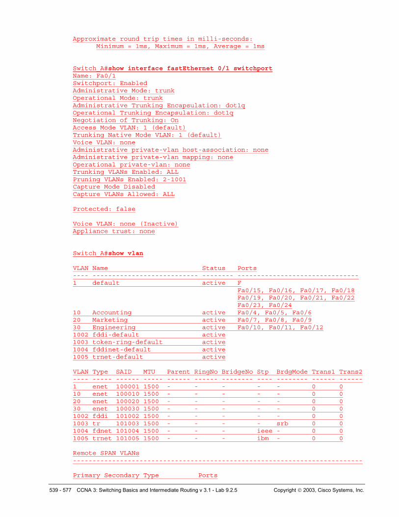
Approximate round trip times in milli-seconds: Minimum = 1ms, Maximum = 1ms, Average = 1ms
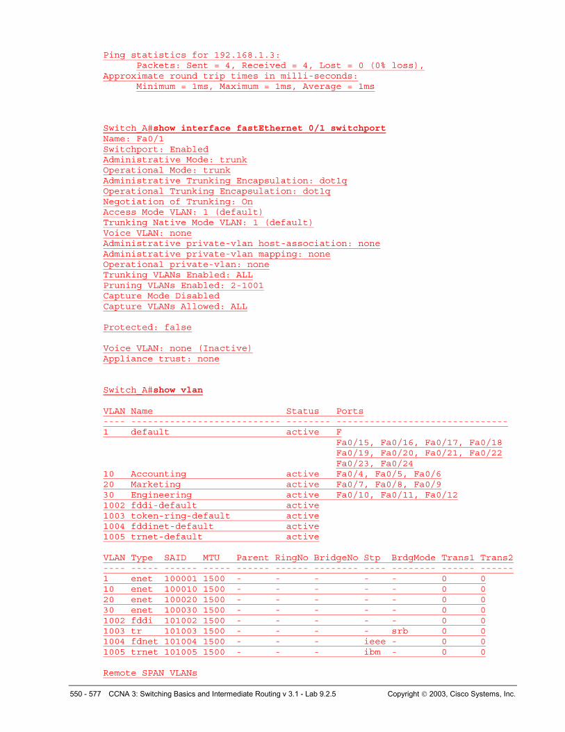
Switch_A#show interface fastEthernet 0/1 switchport Name: Fa0/1 Switchport: Enabled Administrative Mode: trunk Operational Mode: trunk Administrative Trunking Encapsulation: dot1q Operational Trunking Encapsulation: dot1q Negotiation of Trunking: On Access Mode VLAN: 1 (default) Trunking Native Mode VLAN: 1 (default) Voice VLAN: none Administrative private-vlan host-association: none Administrative private-vlan mapping: none Operational private-vlan: none Trunking VLANs Enabled: ALL Pruning VLANs Enabled: 2-1001 Capture Mode Disabled Capture VLANs Allowed: ALL Protected: false Voice VLAN: none (Inactive) Appliance trust: none
Switch_A#show vlan VLAN Name Status Ports ---- --------------------------- -------- ------------------------------- 1 default active F
Fa0/15, Fa0/16, Fa0/17, Fa0/18 Fa0/19, Fa0/20, Fa0/21, Fa0/22 Fa0/23, Fa0/24
10 Accounting active Fa0/4, Fa0/5, Fa0/6 20 Marketing active Fa0/7, Fa0/8, Fa0/9 30 Engineering active Fa0/10, Fa0/11, Fa0/12 1002 fddi-default active 1003 token-ring-default active 1004 fddinet-default active 1005 trnet-default active VLAN Type SAID MTU Parent RingNo BridgeNo Stp BrdgMode Trans1 Trans2 ---- ----- ------ ----- ------ ------ -------- ---- -------- ------ ------ 1 enet 100001 1500 - - - - - 0 0 10 enet 100010 1500 - - - - - 0 0 20 enet 100020 1500 - - - - - 0 0 30 enet 100030 1500 - - - - - 0 0 1002 fddi 101002 1500 - - - - - 0 0 1003 tr 101003 1500 - - - - srb 0 0 1004 fdnet 101004 1500 - - - ieee - 0 0 1005 trnet 101005 1500 - - - ibm - 0 0 Remote SPAN VLANs --------------------------------------------------------------------------
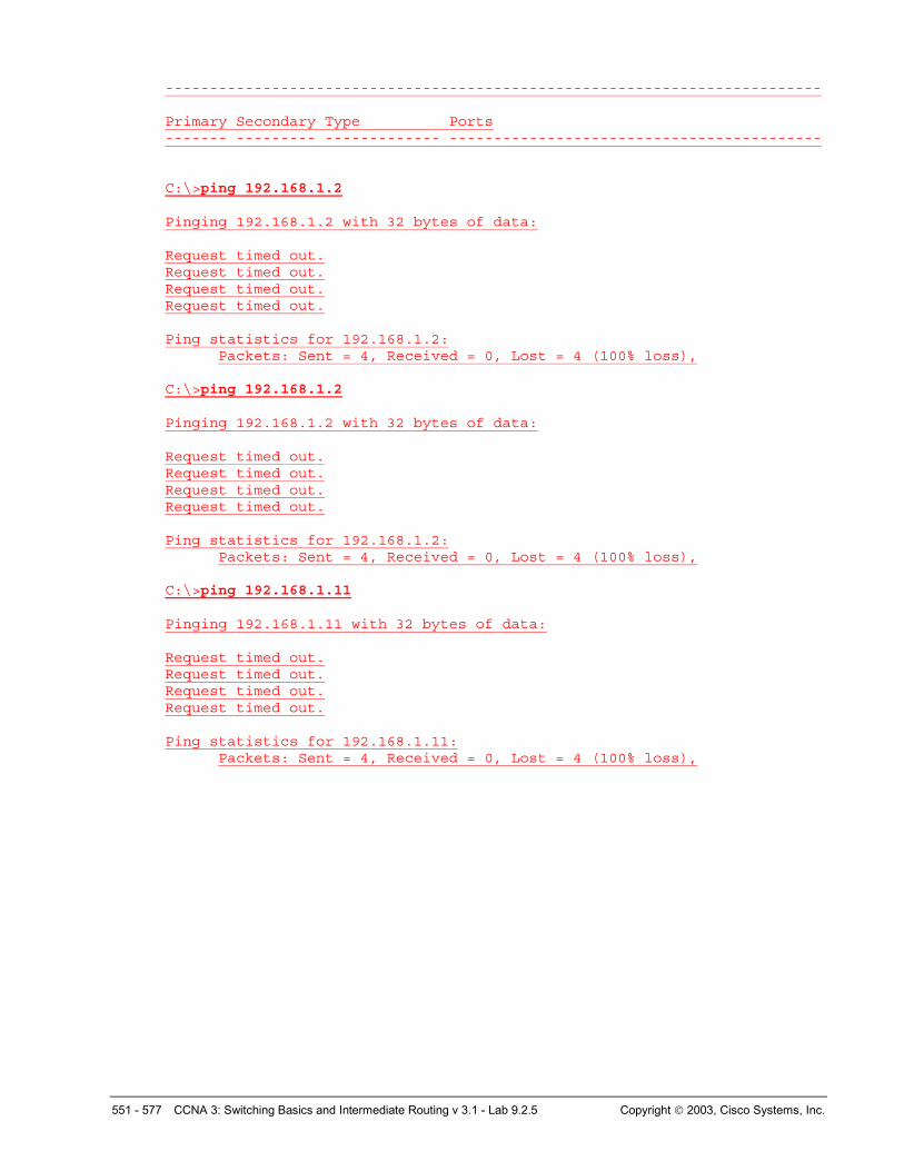
Primary Secondary Type Ports

540 - 577 CCNA 3: Switching Basics and Intermediate Routing v 3.1 - Lab 9.2.5 Copyright 2003, Cisco Systems, Inc.
------- --------- ------------- ------------------------------------------
C:\>ping 192.168.1.2 Pinging 192.168.1.2 with 32 bytes of data: Request timed out. Request timed out. Request timed out. Request timed out. Ping statistics for 192.168.1.2:
Packets: Sent = 4, Received = 0, Lost = 4 (100% loss),
C:\>ping 192.168.1.2 Pinging 192.168.1.2 with 32 bytes of data: Request timed out. Request timed out. Request timed out. Request timed out. Ping statistics for 192.168.1.2:
Packets: Sent = 4, Received = 0, Lost = 4 (100% loss),
C:\>ping 192.168.1.11 Pinging 192.168.1.11 with 32 bytes of data: Request timed out. Request timed out. Request timed out. Request timed out. Ping statistics for 192.168.1.11:
Packets: Sent = 4, Received = 0, Lost = 4 (100% loss),
541 - 577 CCNA 3: Switching Basics and Intermediate Routing v 3.1 - Lab 9.2.5 Copyright 2003, Cisco Systems, Inc.
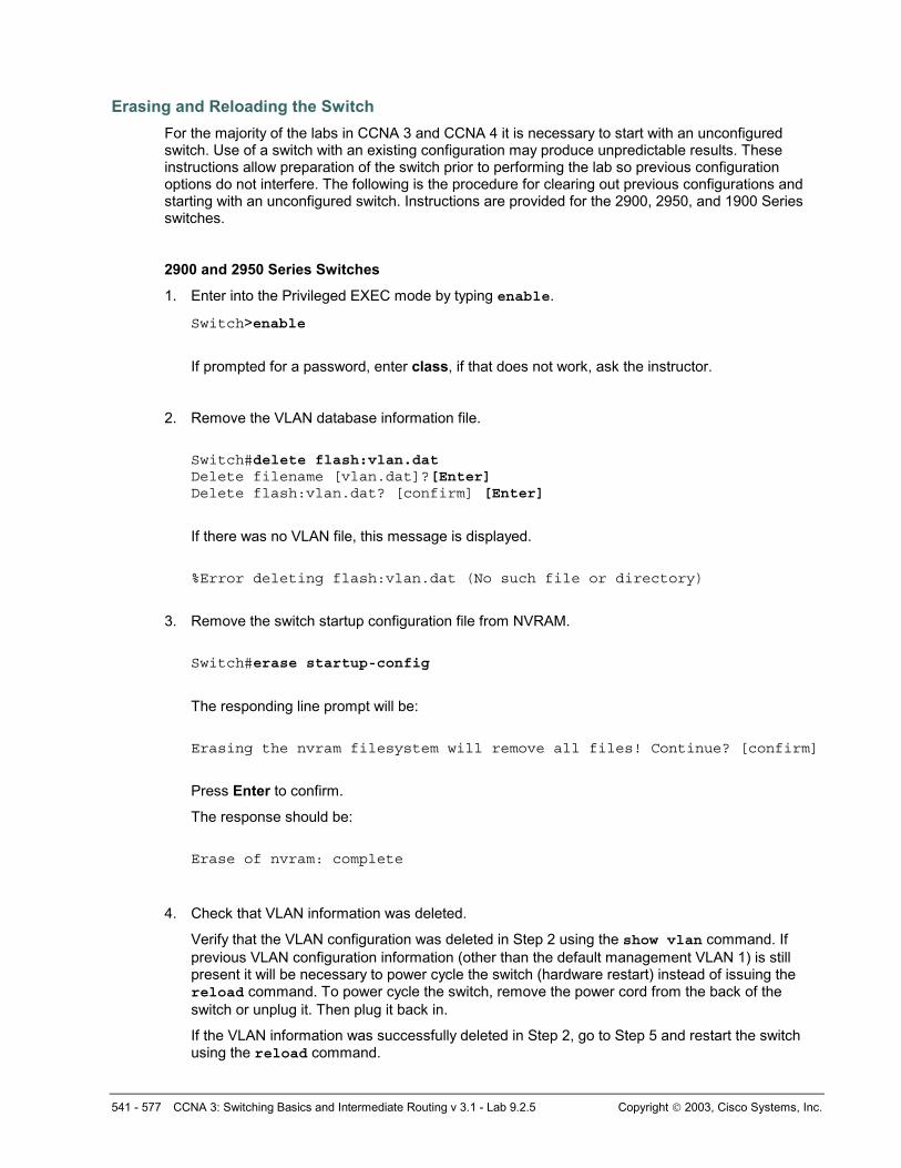
Erasing and Reloading the Switch For the majority of the labs in CCNA 3 and CCNA 4 it is necessary to start with an unconfigured switch. Use of a switch with an existing configuration may produce unpredictable results. These instructions allow preparation of the switch prior to performing the lab so previous configuration options do not interfere. The following is the procedure for clearing out previous configurations and starting with an unconfigured switch. Instructions are provided for the 2900, 2950, and 1900 Series switches.
2900 and 2950 Series Switches
1. Enter into the Privileged EXEC mode by typing enable.
Switch>enable
If prompted for a password, enter class, if that does not work, ask the instructor.
2. Remove the VLAN database information file.
Switch#delete flash:vlan.dat Delete filename [vlan.dat]?[Enter] Delete flash:vlan.dat? [confirm] [Enter]
If there was no VLAN file, this message is displayed.
%Error deleting flash:vlan.dat (No such file or directory)
3. Remove the switch startup configuration file from NVRAM.
Switch#erase startup-config
The responding line prompt will be:
Erasing the nvram filesystem will remove all files! Continue? [confirm]
Press Enter to confirm.
The response should be:
Erase of nvram: complete
4. Check that VLAN information was deleted.
Verify that the VLAN configuration was deleted in Step 2 using the show vlan command. If previous VLAN configuration information (other than the default management VLAN 1) is still present it will be necessary to power cycle the switch (hardware restart) instead of issuing the reload command. To power cycle the switch, remove the power cord from the back of the switch or unplug it. Then plug it back in.
If the VLAN information was successfully deleted in Step 2, go to Step 5 and restart the switch using the reload command.
542 - 577 CCNA 3: Switching Basics and Intermediate Routing v 3.1 - Lab 9.2.5 Copyright 2003, Cisco Systems, Inc.
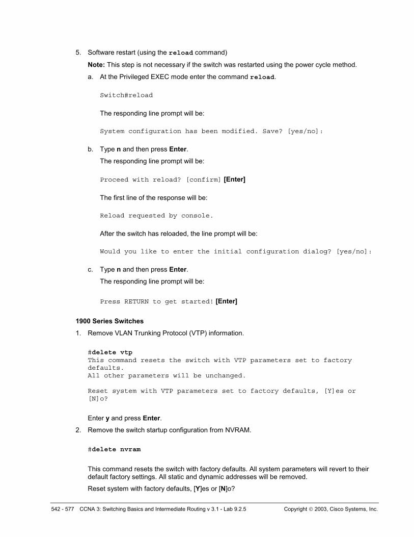
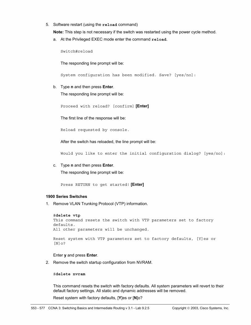
5. Software restart (using the reload command)
Note: This step is not necessary if the switch was restarted using the power cycle method.
a. At the Privileged EXEC mode enter the command reload.
Switch#reload
The responding line prompt will be:
System configuration has been modified. Save? [yes/no]:
b. Type n and then press Enter.
The responding line prompt will be:
Proceed with reload? [confirm] [Enter]
The first line of the response will be:
Reload requested by console.
After the switch has reloaded, the line prompt will be:
Would you like to enter the initial configuration dialog? [yes/no]:
c. Type n and then press Enter.
The responding line prompt will be:
Press RETURN to get started! [Enter]
1900 Series Switches
1. Remove VLAN Trunking Protocol (VTP) information.
#delete vtp This command resets the switch with VTP parameters set to factory defaults. All other parameters will be unchanged. Reset system with VTP parameters set to factory defaults, [Y]es or [N]o?
Enter y and press Enter.
2. Remove the switch startup configuration from NVRAM.
#delete nvram
This command resets the switch with factory defaults. All system parameters will revert to their default factory settings. All static and dynamic addresses will be removed.
Reset system with factory defaults, [Y]es or [N]o?

543 - 577 CCNA 3: Switching Basics and Intermediate Routing v 3.1 - Lab 9.2.5 Copyright 2003, Cisco Systems, Inc.
Enter y and press Enter.

544 - 577 CCNA 3: Switching Basics and Intermediate Routing v 3.1 - Lab 9.2.5 Copyright 2003, Cisco Systems, Inc.
Lab 9.2.5 VTP Client and Server Configurations – 2950 Series
Objective • Create a basic switch configuration and verify it.
• Create multiple VLANs, name them and assign multiple member ports to them.
• Configure the VTP protocol to establish Server and client switches.
• Create an 802.1q trunk line between the two switches to allow communication between paired VLANs.
• Then test the VLANs functionality by moving a workstation from one VLAN to another.
Background/Preparation When managing a switch, the Management Domain is always VLAN 1. The Network Administrator's workstation must have access to a port in the VLAN 1 Management Domain. All ports are assigned to VLAN 1 by default.
545 - 577 CCNA 3: Switching Basics and Intermediate Routing v 3.1 - Lab 9.2.5 Copyright 2003, Cisco Systems, Inc.
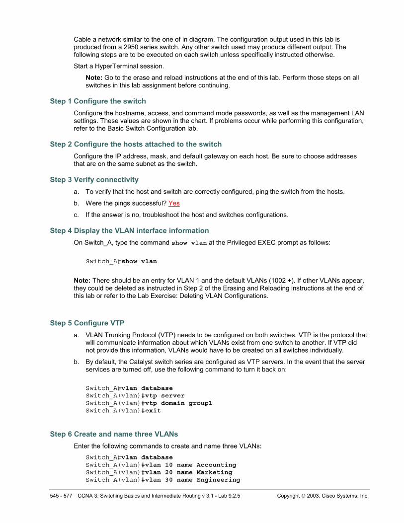
Cable a network similar to the one of in diagram. The configuration output used in this lab is produced from a 2950 series switch. Any other switch used may produce different output. The following steps are to be executed on each switch unless specifically instructed otherwise.
Start a HyperTerminal session.
Note: Go to the erase and reload instructions at the end of this lab. Perform those steps on all switches in this lab assignment before continuing.
Step 1 Configure the switch Configure the hostname, access, and command mode passwords, as well as the management LAN settings. These values are shown in the chart. If problems occur while performing this configuration, refer to the Basic Switch Configuration lab.
Step 2 Configure the hosts attached to the switch Configure the IP address, mask, and default gateway on each host. Be sure to choose addresses that are on the same subnet as the switch.
Step 3 Verify connectivity a. To verify that the host and switch are correctly configured, ping the switch from the hosts.
b. Were the pings successful? Yes
c. If the answer is no, troubleshoot the host and switches configurations.
Step 4 Display the VLAN interface information On Switch_A, type the command show vlan at the Privileged EXEC prompt as follows:
Switch_A#show vlan
Note: There should be an entry for VLAN 1 and the default VLANs (1002 +). If other VLANs appear, they could be deleted as instructed in Step 2 of the Erasing and Reloading instructions at the end of this lab or refer to the Lab Exercise: Deleting VLAN Configurations.
Step 5 Configure VTP a. VLAN Trunking Protocol (VTP) needs to be configured on both switches. VTP is the protocol that
will communicate information about which VLANs exist from one switch to another. If VTP did not provide this information, VLANs would have to be created on all switches individually.
b. By default, the Catalyst switch series are configured as VTP servers. In the event that the server services are turned off, use the following command to turn it back on:
Switch_A#vlan database Switch_A(vlan)#vtp server Switch_A(vlan)#vtp domain group1 Switch_A(vlan)#exit
Step 6 Create and name three VLANs Enter the following commands to create and name three VLANs:
Switch_A#vlan database Switch_A(vlan)#vlan 10 name Accounting Switch_A(vlan)#vlan 20 name Marketing Switch_A(vlan)#vlan 30 name Engineering
546 - 577 CCNA 3: Switching Basics and Intermediate Routing v 3.1 - Lab 9.2.5 Copyright 2003, Cisco Systems, Inc.
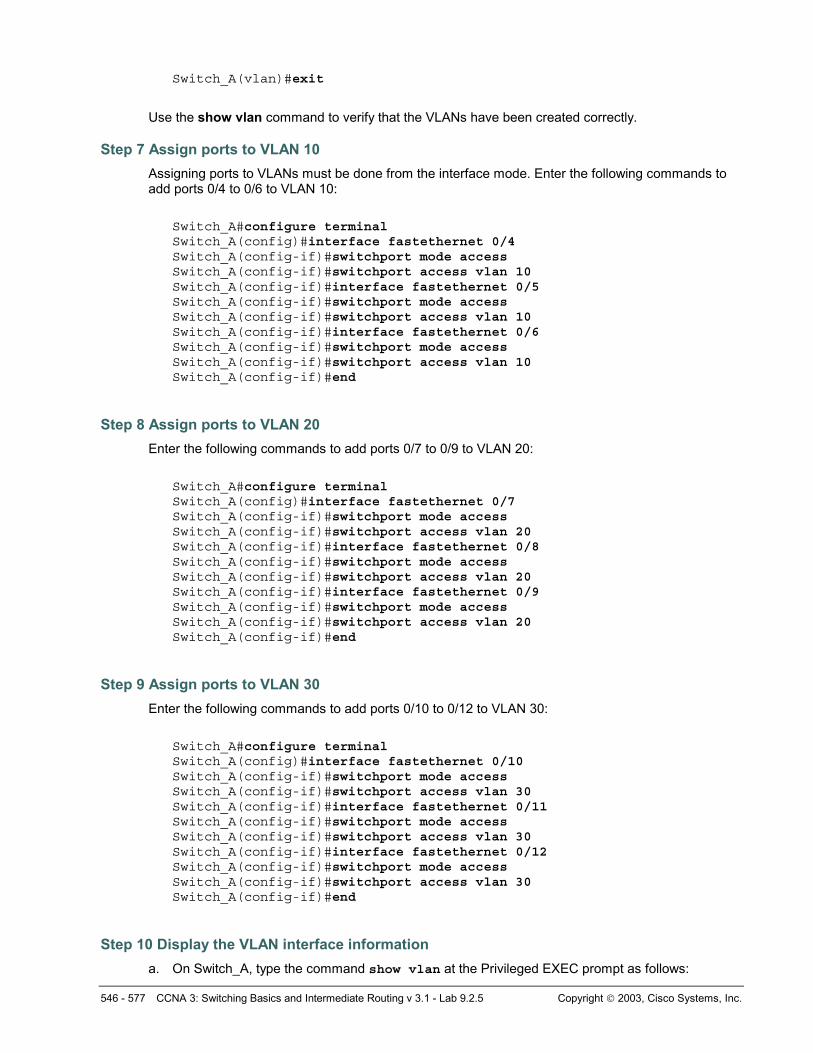
Switch_A(vlan)#exit
Use the show vlan command to verify that the VLANs have been created correctly.
Step 7 Assign ports to VLAN 10 Assigning ports to VLANs must be done from the interface mode. Enter the following commands to add ports 0/4 to 0/6 to VLAN 10:
Switch_A#configure terminal Switch_A(config)#interface fastethernet 0/4 Switch_A(config-if)#switchport mode access Switch_A(config-if)#switchport access vlan 10 Switch_A(config-if)#interface fastethernet 0/5 Switch_A(config-if)#switchport mode access Switch_A(config-if)#switchport access vlan 10 Switch_A(config-if)#interface fastethernet 0/6 Switch_A(config-if)#switchport mode access Switch_A(config-if)#switchport access vlan 10 Switch_A(config-if)#end
Step 8 Assign ports to VLAN 20 Enter the following commands to add ports 0/7 to 0/9 to VLAN 20:
Switch_A#configure terminal Switch_A(config)#interface fastethernet 0/7 Switch_A(config-if)#switchport mode access Switch_A(config-if)#switchport access vlan 20 Switch_A(config-if)#interface fastethernet 0/8 Switch_A(config-if)#switchport mode access Switch_A(config-if)#switchport access vlan 20 Switch_A(config-if)#interface fastethernet 0/9 Switch_A(config-if)#switchport mode access Switch_A(config-if)#switchport access vlan 20 Switch_A(config-if)#end
Step 9 Assign ports to VLAN 30 Enter the following commands to add ports 0/10 to 0/12 to VLAN 30:
Switch_A#configure terminal Switch_A(config)#interface fastethernet 0/10 Switch_A(config-if)#switchport mode access Switch_A(config-if)#switchport access vlan 30 Switch_A(config-if)#interface fastethernet 0/11 Switch_A(config-if)#switchport mode access Switch_A(config-if)#switchport access vlan 30 Switch_A(config-if)#interface fastethernet 0/12 Switch_A(config-if)#switchport mode access Switch_A(config-if)#switchport access vlan 30 Switch_A(config-if)#end
Step 10 Display the VLAN interface information a. On Switch_A, type the command show vlan at the Privileged EXEC prompt as follows:
547 - 577 CCNA 3: Switching Basics and Intermediate Routing v 3.1 - Lab 9.2.5 Copyright 2003, Cisco Systems, Inc.
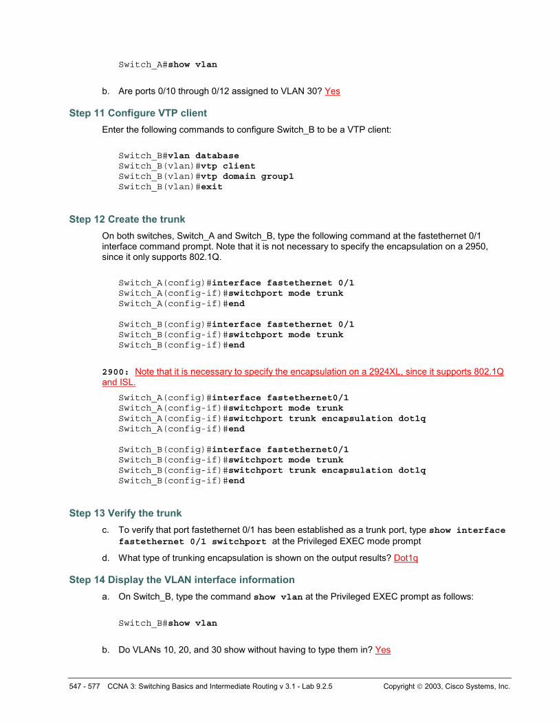
Switch_A#show vlan
b. Are ports 0/10 through 0/12 assigned to VLAN 30? Yes
Step 11 Configure VTP client Enter the following commands to configure Switch_B to be a VTP client:
Switch_B#vlan database Switch_B(vlan)#vtp client Switch_B(vlan)#vtp domain group1 Switch_B(vlan)#exit
Step 12 Create the trunk On both switches, Switch_A and Switch_B, type the following command at the fastethernet 0/1 interface command prompt. Note that it is not necessary to specify the encapsulation on a 2950, since it only supports 802.1Q.
Switch_A(config)#interface fastethernet 0/1 Switch_A(config-if)#switchport mode trunk Switch_A(config-if)#end Switch_B(config)#interface fastethernet 0/1 Switch_B(config-if)#switchport mode trunk Switch_B(config-if)#end
2900: Note that it is necessary to specify the encapsulation on a 2924XL, since it supports 802.1Q and ISL.
Switch_A(config)#interface fastethernet0/1 Switch_A(config-if)#switchport mode trunk Switch_A(config-if)#switchport trunk encapsulation dot1q Switch_A(config-if)#end Switch_B(config)#interface fastethernet0/1 Switch_B(config-if)#switchport mode trunk Switch_B(config-if)#switchport trunk encapsulation dot1q Switch_B(config-if)#end
Step 13 Verify the trunk c. To verify that port fastethernet 0/1 has been established as a trunk port, type show interface
fastethernet 0/1 switchport at the Privileged EXEC mode prompt
d. What type of trunking encapsulation is shown on the output results? Dot1q
Step 14 Display the VLAN interface information a. On Switch_B, type the command show vlan at the Privileged EXEC prompt as follows:
Switch_B#show vlan
b. Do VLANs 10, 20, and 30 show without having to type them in? Yes
548 - 577 CCNA 3: Switching Basics and Intermediate Routing v 3.1 - Lab 9.2.5 Copyright 2003, Cisco Systems, Inc.
c. Why did this happen? Because Switch_A is a VTP server and it sent VLAN information to Switch_B.
Step 15 Assign ports to a VLAN 10 Although the VLAN definitions have migrated to Switch_B using VTP, it is still necessary to assign ports to these VLANs on Switch_B. Assigning ports to VLANs must be done from the interface mode. Enter the following commands to add ports 0/4 to 0/6 to VLAN 10.
Switch_B#configure terminal Switch_B(config)#interface fastethernet 0/4 Switch_B(config-if)#switchport mode access Switch_B(config-if)#switchport access vlan 10 Switch_B(config-if)#interface fastethernet 0/5 Switch_B(config-if)#switchport mode access Switch_B(config-if)#switchport access vlan 10 Switch_B(config-if)#interface fastethernet 0/6 Switch_B(config-if)#switchport mode access Switch_B(config-if)#switchport access vlan 10 Switch_B(config-if)#end
Step 16 Assign ports to VLAN 20 Enter the following commands to add ports 0/7 to 0/9 to VLAN 20:
Switch_B#configure terminal Switch_B(config)#interface fastethernet 0/7 Switch_B(config-if)#switchport mode access Switch_B(config-if)#switchport access vlan 20 Switch_B(config-if)#interface fastethernet 0/8 Switch_B(config-if)#switchport mode access Switch_B(config-if)#switchport access vlan 20 Switch_B(config-if)#interface fastethernet 0/9 Switch_B(config-if)#switchport mode access Switch_B(config-if)#switchport access vlan 20 Switch_B(config-if)#end
Step 17 Assign ports to VLAN 30 Enter the following commands to add ports 0/10 to 0/12 to VLAN 30:
Switch_B#configure terminal Switch_B(config)#interface fastethernet 0/10 Switch_B(config-if)#switchport mode access Switch_B(config-if)#switchport access vlan 30 Switch_B(config-if)#interface fastethernet 0/11 Switch_B(config-if)#switchport mode access Switch_B(config-if)#switchport access vlan 30 Switch_B(config-if)#interface fastethernet 0/12 Switch_B(config-if)#switchport mode access Switch_B(config-if)#switchport access vlan 30 Switch_B(config-if)#end
Step 18 Display the VLAN interface information a. On Switch_B, type the command show vlan at the Privileged EXEC prompt as follows:

549 - 577 CCNA 3: Switching Basics and Intermediate Routing v 3.1 - Lab 9.2.5 Copyright 2003, Cisco Systems, Inc.
Switch_A#show vlan
b. Are ports 0/10 through 0/12 assigned to VLAN 30? Yes, they are assigned to VLAN 30.
Step 19 Test the VLANS and the trunk Ping from the host in Switch_A port 0/12 to the host in Switch_B port 0/12.
a. Was the ping successful? Yes
b. Why? Both hosts are in the same VLAN with the trunk link properly configured.
Ping from the host in Switch_A port 0/12 to the switch IP 192.168.1.2.
c. Was the ping successful? No
d. Why? The interfaces belong to different VLANs.
Step 20 Move hosts Move the host in Switch_A from port 0/12 to port 0/8. Wait until the port LED goes green and then go to the next step.
Step 21 Test the VLANS and the trunk Ping from the host in Switch_A port 0/8 to the host in Switch_B port 0/12.
a. Was the ping successful? No
b. Why? The hosts are on separate VLANs.
Ping from the host in Switch_A port 0/8 to the switch IP 192.168.1.2.
c. Was the ping successful? No
d. Why? The interfaces belong to different VLANs.
Once the steps are complete, logoff by typing exit, and turn all the devices off. Then remove and store the cables and adapter. C:\>ping 192.168.1.2 Pinging 192.168.1.2 with 32 bytes of data: Reply from 192.168.1.2: bytes=32 time=1ms TTL=255 Reply from 192.168.1.2: bytes=32 time=1ms TTL=255 Reply from 192.168.1.2: bytes=32 time=1ms TTL=255 Reply from 192.168.1.2: bytes=32 time=1ms TTL=255 Ping statistics for 192.168.1.2:
Packets: Sent = 4, Received = 4, Lost = 0 (0% loss), Approximate round trip times in milli-seconds:
Minimum = 1ms, Maximum = 1ms, Average = 1ms C:\>ping 192.168.1.3 Pinging 192.168.1.3 with 32 bytes of data: Reply from 192.168.1.3: bytes=32 time=1ms TTL=255 Reply from 192.168.1.3: bytes=32 time=1ms TTL=255 Reply from 192.168.1.3: bytes=32 time=1ms TTL=255 Reply from 192.168.1.3: bytes=32 time=1ms TTL=255
550 - 577 CCNA 3: Switching Basics and Intermediate Routing v 3.1 - Lab 9.2.5 Copyright 2003, Cisco Systems, Inc.
Ping statistics for 192.168.1.3: Packets: Sent = 4, Received = 4, Lost = 0 (0% loss),
Approximate round trip times in milli-seconds: Minimum = 1ms, Maximum = 1ms, Average = 1ms
Switch_A#show interface fastEthernet 0/1 switchport Name: Fa0/1 Switchport: Enabled Administrative Mode: trunk Operational Mode: trunk Administrative Trunking Encapsulation: dot1q Operational Trunking Encapsulation: dot1q Negotiation of Trunking: On Access Mode VLAN: 1 (default) Trunking Native Mode VLAN: 1 (default) Voice VLAN: none Administrative private-vlan host-association: none Administrative private-vlan mapping: none Operational private-vlan: none Trunking VLANs Enabled: ALL Pruning VLANs Enabled: 2-1001 Capture Mode Disabled Capture VLANs Allowed: ALL Protected: false Voice VLAN: none (Inactive) Appliance trust: none
Switch_A#show vlan VLAN Name Status Ports ---- --------------------------- -------- ------------------------------- 1 default active F
Fa0/15, Fa0/16, Fa0/17, Fa0/18 Fa0/19, Fa0/20, Fa0/21, Fa0/22 Fa0/23, Fa0/24
10 Accounting active Fa0/4, Fa0/5, Fa0/6 20 Marketing active Fa0/7, Fa0/8, Fa0/9 30 Engineering active Fa0/10, Fa0/11, Fa0/12 1002 fddi-default active 1003 token-ring-default active 1004 fddinet-default active 1005 trnet-default active VLAN Type SAID MTU Parent RingNo BridgeNo Stp BrdgMode Trans1 Trans2 ---- ----- ------ ----- ------ ------ -------- ---- -------- ------ ------ 1 enet 100001 1500 - - - - - 0 0 10 enet 100010 1500 - - - - - 0 0 20 enet 100020 1500 - - - - - 0 0 30 enet 100030 1500 - - - - - 0 0 1002 fddi 101002 1500 - - - - - 0 0 1003 tr 101003 1500 - - - - srb 0 0 1004 fdnet 101004 1500 - - - ieee - 0 0 1005 trnet 101005 1500 - - - ibm - 0 0 Remote SPAN VLANs
551 - 577 CCNA 3: Switching Basics and Intermediate Routing v 3.1 - Lab 9.2.5 Copyright 2003, Cisco Systems, Inc.
--------------------------------------------------------------------------
Primary Secondary Type Ports ------- --------- ------------- ------------------------------------------
C:\>ping 192.168.1.2 Pinging 192.168.1.2 with 32 bytes of data: Request timed out. Request timed out. Request timed out. Request timed out. Ping statistics for 192.168.1.2:
Packets: Sent = 4, Received = 0, Lost = 4 (100% loss),
C:\>ping 192.168.1.2 Pinging 192.168.1.2 with 32 bytes of data: Request timed out. Request timed out. Request timed out. Request timed out. Ping statistics for 192.168.1.2:
Packets: Sent = 4, Received = 0, Lost = 4 (100% loss),
C:\>ping 192.168.1.11 Pinging 192.168.1.11 with 32 bytes of data: Request timed out. Request timed out. Request timed out. Request timed out. Ping statistics for 192.168.1.11:
Packets: Sent = 4, Received = 0, Lost = 4 (100% loss),

552 - 577 CCNA 3: Switching Basics and Intermediate Routing v 3.1 - Lab 9.2.5 Copyright 2003, Cisco Systems, Inc.
Erasing and Reloading the Switch For the majority of the labs in CCNA 3 and CCNA 4 it is necessary to start with an unconfigured switch. Use of a switch with an existing configuration may produce unpredictable results. These instructions allow preparation of the switch prior to performing the lab so previous configuration options do not interfere. The following is the procedure for clearing out previous configurations and starting with an unconfigured switch. Instructions are provided for the 2900, 2950, and 1900 Series switches.
2900 and 2950 Series Switches
1. Enter into the Privileged EXEC mode by typing enable.
Switch>enable
If prompted for a password, enter class, if that does not work, ask the instructor.
2. Remove the VLAN database information file.
Switch#delete flash:vlan.dat Delete filename [vlan.dat]?[Enter] Delete flash:vlan.dat? [confirm] [Enter]
If there was no VLAN file, this message is displayed.
%Error deleting flash:vlan.dat (No such file or directory)
3. Remove the switch startup configuration file from NVRAM.
Switch#erase startup-config
The responding line prompt will be:
Erasing the nvram filesystem will remove all files! Continue? [confirm]
Press Enter to confirm.
The response should be:
Erase of nvram: complete
4. Check that VLAN information was deleted.
Verify that the VLAN configuration was deleted in Step 2 using the show vlan command. If previous VLAN configuration information (other than the default management VLAN 1) is still present it will be necessary to power cycle the switch (hardware restart) instead of issuing the reload command. To power cycle the switch, remove the power cord from the back of the switch or unplug it. Then plug it back in.
If the VLAN information was successfully deleted in Step 2, go to Step 5 and restart the switch using the reload command.
553 - 577 CCNA 3: Switching Basics and Intermediate Routing v 3.1 - Lab 9.2.5 Copyright 2003, Cisco Systems, Inc.
5. Software restart (using the reload command)
Note: This step is not necessary if the switch was restarted using the power cycle method.
a. At the Privileged EXEC mode enter the command reload.
Switch#reload
The responding line prompt will be:
System configuration has been modified. Save? [yes/no]:
b. Type n and then press Enter.
The responding line prompt will be:
Proceed with reload? [confirm] [Enter]
The first line of the response will be:
Reload requested by console.
After the switch has reloaded, the line prompt will be:
Would you like to enter the initial configuration dialog? [yes/no]:
c. Type n and then press Enter.
The responding line prompt will be:
Press RETURN to get started! [Enter]
1900 Series Switches
1. Remove VLAN Trunking Protocol (VTP) information.
#delete vtp This command resets the switch with VTP parameters set to factory defaults. All other parameters will be unchanged. Reset system with VTP parameters set to factory defaults, [Y]es or [N]o?
Enter y and press Enter.
2. Remove the switch startup configuration from NVRAM.
#delete nvram
This command resets the switch with factory defaults. All system parameters will revert to their default factory settings. All static and dynamic addresses will be removed.
Reset system with factory defaults, [Y]es or [N]o?

554 - 577 CCNA 3: Switching Basics and Intermediate Routing v 3.1 - Lab 9.2.5 Copyright 2003, Cisco Systems, Inc.
Enter y and press Enter.