lab manual machining and forming processes (me 785)
TRANSCRIPT

CHAROTAR UNIVERSITY OF SCIENCE & TECHNOLOGYFACULTY OF TECHNOLOGY & ENGINEERINGCHAMOS Matrusanstha Department of Mechanical Engineering
1
LAB MANUAL
Machining and Forming Processes
(ME 785)
CHAROTAR UNIVERSITY OF SCIENCE & TECHNOLOGYFACULTY OF TECHNOLOGY & ENGINEERINGCHAMOS Matrusanstha Department of Mechanical Engineering
2
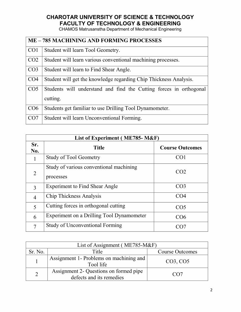
ME – 785 MACHINING AND FORMING PROCESSES
CO1 Student will learn Tool Geometry.
CO2 Student will learn various conventional machining processes.
CO3 Student will learn to Find Shear Angle.
CO4 Student will get the knowledge regarding Chip Thickness Analysis.
CO5 Students will understand and find the Cutting forces in orthogonal
cutting.
CO6 Students get familiar to use Drilling Tool Dynamometer.
CO7 Student will learn Unconventional Forming.
List of Experiment ( ME785- M&F)Sr.No. Title Course Outcomes
1 Study of Tool Geometry CO1
2Study of various conventional machining
processesCO2
3 Experiment to Find Shear Angle CO3
4 Chip Thickness Analysis CO4
5 Cutting forces in orthogonal cutting CO5
6 Experiment on a Drilling Tool Dynamometer CO6
7 Study of Unconventional Forming CO7
List of Assignment ( ME785-M&F)Sr. No. Title Course Outcomes
1 Assignment 1- Problems on machining andTool life CO3, CO5
2 Assignment 2- Questions on formed pipedefects and its remedies CO7

CHAROTAR UNIVERSITY OF SCIENCE & TECHNOLOGYFACULTY OF TECHNOLOGY & ENGINEERINGCHAMOS Matrusanstha Department of Mechanical Engineering
3
INDEX
Sr.No.
PerformanceDate
TitleNo.of
PagesMarks
AssessmentDate Sign
1 Study of Tool Geometry
2 Study of various conventionalmachining processes
3Experiment to Find ShearAngle
4 Chip Thickness Analysis
5Cutting forces in orthogonalcutting
6Experiment on a Drilling ToolDynamometer
7Study of UnconventionalForming

CHAROTAR UNIVERSITY OF SCIENCE & TECHNOLOGYFACULTY OF TECHNOLOGY & ENGINEERINGCHAMOS Matrusanstha Department of Mechanical Engineering
4
Machining and Forming Processes (ME-785) Date:
EXPERIMENT No. 1
STUDY OF TOOL GEOMETRY
AIM:
STUDY OF TOOL GEOMETRY OF SINGLE POINT, MULTI POINTCUTTING TOOL.
THEORY:
It is an instrumental media which helps to remove material from the work piece,and to give desired shape and size with the help of single point contact tool ormulti point cutting tool. The relative motion is established between work and thecutting tool to undergo cutting process.
According to different methods-
According to method of manufacturing-
Forged tool, Tipped tool brazed to the carbon steel shank, Tipped tool fastenedmechanically to the carbon steel shank.
According to the method of holding the tool- Solid tool, Tool bit inserted in thetool holder.
According to the method of using the tool- Turning, Chamfering, Threadcutting, Facing, Grooving, Forming, Boring, Internal thread cutting, parting off.
According to the method of applying the feed- Right hand, Left hand, Roundnose.

CHAROTAR UNIVERSITY OF SCIENCE & TECHNOLOGYFACULTY OF TECHNOLOGY & ENGINEERINGCHAMOS Matrusanstha Department of Mechanical Engineering
5
Fig. - Nomenclature of Single point cutting tool

CHAROTAR UNIVERSITY OF SCIENCE & TECHNOLOGYFACULTY OF TECHNOLOGY & ENGINEERINGCHAMOS Matrusanstha Department of Mechanical Engineering
6
QUESTIONS:
1. Explain with the help of neat sketch the complex geometry of a single point
cutting tool and Multi point cutting tool.
2. State the different types of the tool nomenclature system. Explain briefly
ASA system and ORS system of tool nomenclature with neat sketch.
3. Explain orthogonal cutting and oblique cutting.
Marks obtained Signature of faculty Date

CHAROTAR UNIVERSITY OF SCIENCE & TECHNOLOGYFACULTY OF TECHNOLOGY & ENGINEERINGCHAMOS Matrusanstha Department of Mechanical Engineering
7
Machining and Forming Processes (ME-785) Date:
EXPERIMENT No. 2
STUDY OF VARIOUS CONVENTIONAL MACHINING PROCESSES
AIM:
TO STUDY OF VARIOUS CONVENTIONAL MACHINING PROCESSES.
INTRODUCTION:
Machining is any of various processes in which a piece of raw material is cut into adesired final shape and size by a controlled material-removal process. Theprocesses that have this common theme, controlled material removal, are todaycollectively known as subtractive manufacturing, in distinction from processes ofcontrolled material addition, which are known as additive manufacturing. Exactlywhat the "controlled" part of the definition implies can vary, but it almost alwaysimplies the use of machine tools (in addition to just power tools and hand tools).
Machining is a part of the manufacture of many metal products, but it can also beused on materials such as wood, plastic, ceramic, and composites. A person whospecializes in machining is called a machinist. A room, building, or companywhere machining is done is called a machine shop. Machining can be a business,a hobby, or both. Much of modern day machining is carried out by computernumerical control (CNC), in which computers are used to control the movementand operation of the mills, lathes, and other cutting machines.
"Traditional" or "conventional" machining processes, machine tools, suchas lathes, milling machines, drill presses, or others, are used with a sharp cuttingtool to remove material to achieve a desired geometry.
So ultimately Machining is any process in which a cutting tool is used to removesmall chips of material from the workpiece (the workpiece is often called the

CHAROTAR UNIVERSITY OF SCIENCE & TECHNOLOGYFACULTY OF TECHNOLOGY & ENGINEERINGCHAMOS Matrusanstha Department of Mechanical Engineering
8
"work"). To perform the operation, relative motion is required between the tool andthe work. This relative motion is achieved in most machining operation by meansof a primary motion, called "cutting speed" and a secondary motion called "feed".The shape of the tool and its penetration into the work surface, combined withthese motions, produce the desired shape of the resulting work surface.
MACHINING OPERATIONS:There are many kinds of machining operations, each of which is capable ofgenerating a certain part geometry and surface texture.In turning, a cutting tool with a single cutting edge is used to remove material froma rotating workpiece to generate a cylindrical shape. The primary motion isprovided by rotating the workpiece, and the feed motion is achieved by moving thecutting tool slowly in a direction parallel to the axis of rotation of the workpiece.Drilling is used to create a round hole. It is accomplished by a rotating tool thattypically has two or four helical cutting edges. The tool is fed in a direction parallelto its axis of rotation into the workpiece to form the round hole.In boring, a tool with a single bent pointed tip is advanced into a roughly made holein a spinning workpiece to slightly enlarge the hole and improve its accuracy. It isa fine finishing operation used in the final stages of product manufacture.Reaming is one of the sizing operations that remove a small amount of metal from ahole that already drilled.In milling, a rotating tool with multiple cutting edges is moved slowly relative to thematerial to generate a plane or straight surface. The direction of the feed motion isperpendicular to the tool's axis of rotation. The speed motion is provided by therotating milling cutter. The two basic forms of milling are peripheral milling andface milling.
Questions:1. Discuss and attach any two research papers on “current research trends in
conventional machining processes.”
Marks obtained Signature of faculty Date
CHAROTAR UNIVERSITY OF SCIENCE & TECHNOLOGYFACULTY OF TECHNOLOGY & ENGINEERINGCHAMOS Matrusanstha Department of Mechanical Engineering
9
Machining and Forming Processes (ME-785) Date:
EXPERIMENT No. 3
EXPERIMENT TO FIND SHEAR ANGLE
AIM:
TO EVALUATE SHEAR ANGLE AS A FUNCTION OF THE RAKE ANGLEOF THE TOOL
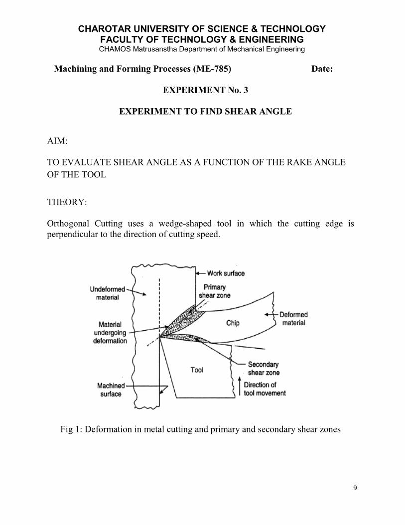
THEORY:
Orthogonal Cutting uses a wedge-shaped tool in which the cutting edge isperpendicular to the direction of cutting speed.
Fig 1: Deformation in metal cutting and primary and secondary shear zones

CHAROTAR UNIVERSITY OF SCIENCE & TECHNOLOGYFACULTY OF TECHNOLOGY & ENGINEERINGCHAMOS Matrusanstha Department of Mechanical Engineering
10
Fig 2: Illustrating the shear zone (ABCD), shear plane and shear angle (ɸ)
Primary deformation zone– shear in the work materialSecondary deformation zone – friction between chip and rake faceTertiary deformation zone– friction between machined surface and flank face
Shear plane:
As the tool is forced into the material, the chip is formed by shear deformationalong a plane called the shear plane.
Chip thickness ratio (or chip ratio):
Shear angle:

CHAROTAR UNIVERSITY OF SCIENCE & TECHNOLOGYFACULTY OF TECHNOLOGY & ENGINEERINGCHAMOS Matrusanstha Department of Mechanical Engineering
11
Fig 3: Illustrating shear angle (ɸ), shear plane and rake angle (α)
The Merchant equation defines the general relationship between rake angle, tool-chip friction, and shear plane angle as under:
Where, = shear angle
rake angle
= friction angle
OBSERVATIONS:
Tool Material:
Workpiece Material:
Spindle Speed (rpm):

CHAROTAR UNIVERSITY OF SCIENCE & TECHNOLOGYFACULTY OF TECHNOLOGY & ENGINEERINGCHAMOS Matrusanstha Department of Mechanical Engineering
12
Depth of Cut:
OBSERVATION TABLE:
Test
Side RakeAngle,
α (Degrees)Feed t1,(mm)
Chip Thickness t2
(mm)Theoretical Shear
Angle,ɸ(Degrees)
Practical Shear Angleɸ(Degrees)
1 -5
2 0
3 +5
4 +10
5 +15
6 +20
7 +25
8 +30
GRAPH:
Rake angle vs. Chip thickness
Rake angle vs. Theoretical shear angle
Rake angle vs. Practical shear angle
CONCLUSION:

CHAROTAR UNIVERSITY OF SCIENCE & TECHNOLOGYFACULTY OF TECHNOLOGY & ENGINEERINGCHAMOS Matrusanstha Department of Mechanical Engineering
13
Marks obtained Signature of faculty Date
CHAROTAR UNIVERSITY OF SCIENCE & TECHNOLOGYFACULTY OF TECHNOLOGY & ENGINEERINGCHAMOS Matrusanstha Department of Mechanical Engineering
14
Machining and Forming Processes (ME-785) Date:
EXPERIMENT No. 4
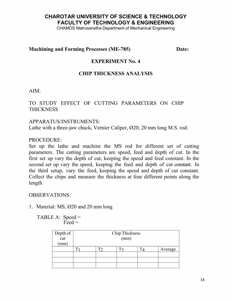
CHIP THICKNESS ANALYSIS
AIM:
TO STUDY EFFECT OF CUTTING PARAMETERS ON CHIPTHICKNESS
APPARATUS/INSTRUMENTS:Lathe with a three-jaw chuck, Vernier Caliper, Ø20; 20 mm long M.S. rod.
PROCEDURE:Set up the lathe and machine the MS rod for different set of cuttingparameters. The cutting parameters are speed, feed and depth of cut. In thefirst set up vary the depth of cut, keeping the speed and feed constant. In thesecond set up vary the speed, keeping the feed and depth of cut constant. Inthe third setup, vary the feed, keeping the speed and depth of cut constant.Collect the chips and measure the thickness at four different points along thelength
OBSERVATIONS:
1. Material: MS, Ø20 and 20 mm long
TABLE A: Speed =Feed =
Depth ofcut
(mm)
Chip Thickness(mm)
T1 T2 T3 T4 Average

CHAROTAR UNIVERSITY OF SCIENCE & TECHNOLOGYFACULTY OF TECHNOLOGY & ENGINEERINGCHAMOS Matrusanstha Department of Mechanical Engineering
15
TABLE B: Feed =Depth of cut =
Speed(rpm)
Chip Thickness(mm)
T1 T2 T3 T4 Average
TABLE C: Speed =Depth of cut =
Feed(mm/rev)
Chip Thickness(mm)
T1 T2 T3 T4 Average
GRAPHS:
TABLE A: Depth of cut Vs Chip ThicknessTABLE B: Speed Vs Chip ThicknessTABLE C: Feed Vs Chip Thickness
CONCLUSION:

CHAROTAR UNIVERSITY OF SCIENCE & TECHNOLOGYFACULTY OF TECHNOLOGY & ENGINEERINGCHAMOS Matrusanstha Department of Mechanical Engineering
16
Marks obtained Signature of faculty DateMachining and Forming Processes (ME-785) Date:
EXPERIMENT No. 5
CUTTING FORCES IN ORTHOGONAL CUTTING
AIM:TO STUDY VARIOUS CUTTING FORCES IN ORTHOGONAL CUTTING.
INTRODUCTION:
Forces acting on the tool in orthogonal cutting are shown in fig.
Cutting force Fc acts in the direction of cutting speed V and supplies theenergy required for the machining operation.
Thrust force Ft acts in the direction normal to the cutting velocity. The two forces produces the resultant force R which can be resolved into
two components acting on tool (friction force F resisting the flow of chip onrake face and normal force N perpendicular to F.)
The resultant force R of F and N is oriented at β called the friction angle.

CHAROTAR UNIVERSITY OF SCIENCE & TECHNOLOGYFACULTY OF TECHNOLOGY & ENGINEERINGCHAMOS Matrusanstha Department of Mechanical Engineering
17
Fs shear force that causes shear deformation and Fn normal to Fs.
Problem 1: During turning a ductile alloy by a tool of γ0 =100, it isfound PZ=1000 N, Px=400 N, Py=300 N and ζ=2.5.Evaluate using MCD, thevalues of F,N and µ as well as PS and Pn for the above machining.
Problem 2: During turning a steel rod of diameter 160 mm at speed 560 rpm,feed 0.32 mm/rev and depth of cut 4.0 mm by a ceramic insert of geometry00,-100, 60, 60, 150, 750, 0(mm)The following was observed:Pz=1600 N, Px=800 N and chip thickness=1mm. Determine with the help ofMCD the possible values of F, N, µa, PS and Pn cutting power and specificenergy consumption.
Problem 3: For turning a given steel rod by a tool of given geometry if shearforce PS, Frictional force F and shear angle γ0 could be estimated to be 400Nand 300N resp. then what would be the possible values of Px, PY And PZ? UseMCD.
Problem 4: During shaping like single point machining/turning) a steel plate atfeed, 0.20 mm/stroke and depth 4 mm by a tool of λ = γ = 0o and φ = 90o Pzand Px were found (measured by dynamometer) to be 800 N and 400 Nrespectively, chip thickness, a2 is 0.4 mm. From the aforesaid conditions andusing Merchant’s Circle Diagram determine the yield shear strength of thework material in the machining condition.

CHAROTAR UNIVERSITY OF SCIENCE & TECHNOLOGYFACULTY OF TECHNOLOGY & ENGINEERINGCHAMOS Matrusanstha Department of Mechanical Engineering
18
Marks obtained Signature of faculty Date
Machining and Forming Processes (ME-785) Date:
EXPERIMENT No. 6
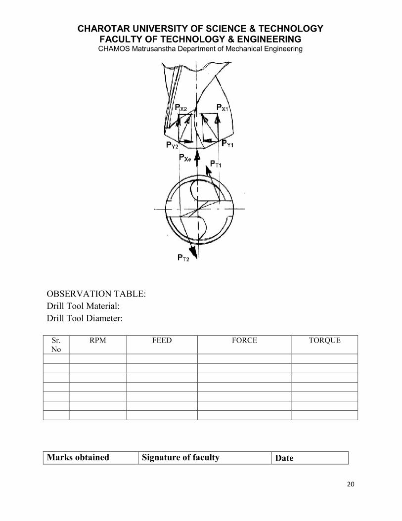
EXPERIMENT ON DRILLING TOOL DYNAMOMETER
AIM:
TO STUDY EFFECT OF INPUT PARAMETER ON FORCE IN DRILLINGMACHINE.
APPARATUS:
Drilling machineDrilling toolDrilling tool dynamometer
THEORY:
In a drill there are two main cutting edges and a small chisel edge at the centre asshown in Fig.
The force components that develop during drilling operation are:
• a pair of tangential forces, PT1 and PT2 (equivalent to PZ in turning) at themain cutting edges
• axial forces PX1 and PX2 acting in the same direction• a pair of identical radial force components, PY1 and PY2
• One additional axial force, PXe at the chisel edge which also removesmaterial at the centre and under more stringent condition.

CHAROTAR UNIVERSITY OF SCIENCE & TECHNOLOGYFACULTY OF TECHNOLOGY & ENGINEERINGCHAMOS Matrusanstha Department of Mechanical Engineering
19
PT1
and PT2
produce the torque, T and causes power consumption PC
as,
T = PT
x ½ (D)
and
PC= 2πTN
Where,
D = diameter of the drillN = speed of the drill in rpm.
The total axial force PXT
which is normally very large in drilling, is provided by
PXT
= PX1
+ PX2
+ PXe
But there is no radial or transverse force as PY1 and PY2, being in oppositedirection, nullify each other if the tool geometry is perfectly symmetrical.
CHAROTAR UNIVERSITY OF SCIENCE & TECHNOLOGYFACULTY OF TECHNOLOGY & ENGINEERINGCHAMOS Matrusanstha Department of Mechanical Engineering
20
OBSERVATION TABLE:Drill Tool Material:Drill Tool Diameter:
Sr.No
RPM FEED FORCE TORQUE
Marks obtained Signature of faculty Date

CHAROTAR UNIVERSITY OF SCIENCE & TECHNOLOGYFACULTY OF TECHNOLOGY & ENGINEERINGCHAMOS Matrusanstha Department of Mechanical Engineering
21
Machining and Forming Processes (ME-785) Date:
EXPERIMENT No. 7
STUDY OF UNCONVENTIONAL FORMING
AIM:
TO STUDY THE DIFFERENT UNCONVENTIONAL FORMING PROCESSES.
INTRODUCTION:
Numerous technological forming processes achieve deformations, which aresubstantially higher than those achieved during the tensile test. One of theturbulently developing areas is the development of nano-structural materials,which is currently one of the priority areas of scientific research in the field ofmaterials and forming technologies all over the world. This concern in particularforming of non-ferrous metals and their alloys. At the same time they bringsignificant reduction of manufacturing costs for products made from thesematerials. Importance of their use, particularly in the automotive industry, militaryand aerospace industries is ever increasing. Major world car makers, such as Opel,Audi, Jaguar, Ford, Fiat, Volvo and Toyota are at present developing an entirelynew concept of fuel-efficient cars with a high share of aluminium and its alloys. Alalloys with ultra-fine structure serve as basic, initial semi-product. Theirdevelopment uses technologies for achievement of nano-structural materials.Achievement of ultra-fine grained structure in initial material leads to substantialincrease of plasticity and makes it possible to form materials in conditions of superplastic state.
Man’s quest to produce large, complicated components out of tougher materialshas resulted in the search for new methods of manufacturer. The high energy rateforming processes makes use of the releases of the energy from high energycontent substances such as explosive. The important processes under this categoryare explosive forming, electromagnetic forming and electro hydraulic forming.
Brief explanation of some of the unconventional forming processes is as under:

CHAROTAR UNIVERSITY OF SCIENCE & TECHNOLOGYFACULTY OF TECHNOLOGY & ENGINEERINGCHAMOS Matrusanstha Department of Mechanical Engineering
22
1. ECAP (Equal channel Angular Pressing):
Application of the ECAP method makes it possible to obtain an ultra-fined grain inlarger volumes, when the initial cross-section does not change during extrusion. Itfinds an important of use namely in automotive industry and also in military andaerospace industries. The products manufactured by this technology meet the basicpre-requisites for their subsequent use at super-plastic forming. Diagram of theEqual Channel Angular Pressing (ECAP) method is shown in Fig.
Fig.: Schematic illustration of the ECAP method

CHAROTAR UNIVERSITY OF SCIENCE & TECHNOLOGYFACULTY OF TECHNOLOGY & ENGINEERINGCHAMOS Matrusanstha Department of Mechanical Engineering
23
The machined specimen is inserted into the L-shaped matrix. For the case when theangle between two parts of the L-shaped matrix is equal to 90 , the test specimenis exposed to shear at the moment of transition from one part into another. It isevident that specimens are extruded in the channel without any change of theirdimensions in the cross-section. By this the given process differs from majority ofusual methods of metal forming, such as rolling and extrusion, which areaccompanied by reduction of cross-section of the processed piece, and where thedeformation is achieved by the change of the initial cross-section. In practice it isappropriate to define individual planes inside the specimen extruded by the ECAPtechnology, namely the plane X perpendicular to the longitudinal axis, and theplanes Y and Z that are parallel to the lateral and top face of the specimen
2. Accumulative Roll Bonding:
The plate is in this process cut to two equally large parts, one part is thoroughlycleaned, the parts are put one onto another and then they are re-rolled to theoriginal width. This rolling should ensure a diffusion welding of both plates, that'swhy this process requires mostly higher temperatures and low strain rates. Theplate has after processing again the initial dimensions, it can be therefore cut againto two equally large parts and the process can be repeated as many times asneeded. Schematic diagram of this method, which is currently intensivelyinvestigated in Japan, is shown in Fig. At present experiments are carried outattempting production of finely crystallised steel and aluminium alloy.

CHAROTAR UNIVERSITY OF SCIENCE & TECHNOLOGYFACULTY OF TECHNOLOGY & ENGINEERINGCHAMOS Matrusanstha Department of Mechanical Engineering
24
Fig.: Schematic illustration of the ARB method
Disadvantage of this method is considerable heterogeneity of structure connectedwith an elongated shape of the deformed grain. Apart from this the contact surfaceof both plates must be carefully cleaned before each rolling, which increasesproduction costs.
3. HIGH ENERGY RATE FORMING
High energy rate forming is the forming of sheet metal by a high energy surge,delivered over a very short time. Since the forming of the metal occurs so quickly,desirable materials for (HERF) will be ductile at high deformation speeds.

CHAROTAR UNIVERSITY OF SCIENCE & TECHNOLOGYFACULTY OF TECHNOLOGY & ENGINEERINGCHAMOS Matrusanstha Department of Mechanical Engineering
25
EXPLOSIVE FORMING-
Explosives can deliver a huge amount of power. Although most explosivedetonations are destructive, the power from an explosive charge can be used tomanufacture parts. An explosive forming process commonly used for theproduction of large parts is called a standoff system. Typically the mold and workpiece are submerged in water. The sheet metal is secured over the mold by a ringclamp. Air is drawn out, creating a vacuum in the die cavity. An explosive isplaced between the die cavity and the work, a certain distance from the work. Thisdistance is called the standoff distance. Standoff distance depends on the size ofthe work, for larger parts it is usually about half the diameter of the blank. Theexplosive itself is also deeply submersed in water. Upon detonation, the shockwave travels through the water and delivers great energy to the work, forming it tothe die cavity near instantaneously. This high energy rate forming process can beused to form big thick plates.
Explosive forming has a long cycle time and is suitable for low quantity productionof large, unique parts. Mechanical properties imparted to the material as a result ofthe explosive forming process are similar to mechanical properties imparted towork manufactured by other forming processes. Molds can be made out ofinexpensive or easy to shape materials, or molds can be made more permanent.Materials for molds include aluminum, wood, concrete, plastic, iron and steel. If amold is manufactured from a material such as plastic, the low modulus of elasticitywill greatly reduce spring back in the sheet metal, resulting in higher accuracy.

CHAROTAR UNIVERSITY OF SCIENCE & TECHNOLOGYFACULTY OF TECHNOLOGY & ENGINEERINGCHAMOS Matrusanstha Department of Mechanical Engineering
26
The amount of explosive depends upon the type of system used and the amount ofpressure needed to form the part. The shock wave generated by the explosivetravels along an expanding spherical front. Much of the energy from the shockwave is not absorbed by the work piece. A modified setup of the standoff systemuses reflectors to focus the energy surge. This provides a more effective use ofpower and a smaller explosive can be used to form the same part. Another systemcalled a confined system uses a canned explosive or cartridge. This is usually usedfor relatively smaller parts than the standoff system. All of the energy is directedinto a closed container, the walls of which contain the die cavity. The energy fromthe canned explosive forces the sheet metal into the walls of the mold, forming thepart. Safety is always a consideration when manufacturing by explosive forming,particularly with the confined system, where die failure is a significant concern.
4. STRETCH FORMING
Stretch forming simultaneouslystretches and bends a piece ofsheet metal to form a largecontoured shape. Automanufacturers use the process toproduce outer-body panels;aircraft manufacturers stretch-form fuselage skin sections.Benefits of the process include alack surface marring, distortionsand ripples, and accuratealignment of complex profiles.
Stretch forming occurs in astretch press, with the sheetmetal securely held along its edges by gripping jaws. The gripping jaws, attachedto a carriage, are pulled by pneumatic or hydraulic force to stretch the sheet (Fig.).The tooling used a stretch form block comprises a solid contoured piece againstwhich the sheet metal is pressed. As the form die drives into the sheet, tensileforces increase until the sheet plastically deforms into its new shape.

CHAROTAR UNIVERSITY OF SCIENCE & TECHNOLOGYFACULTY OF TECHNOLOGY & ENGINEERINGCHAMOS Matrusanstha Department of Mechanical Engineering
27
Stampers select from two basic types of stretch-forming equipment: longitudinaland transverse. Longitudinal equipment stretches the workpiece along its length;transverse equipment stretches the workpiece along its width. Stretch presses aredesigned to be accurate and efficient, while CNC controls help provide part-to-partrepeatability.
Questions:
1. Write down the differences between conventional and unconventional formingprocesses.
2. Write any two case studies on any unconventional forming processes.
Marks obtained Signature of faculty Date

CHAROTAR UNIVERSITY OF SCIENCE & TECHNOLOGYFACULTY OF TECHNOLOGY & ENGINEERINGCHAMOS Matrusanstha Department of Mechanical Engineering
28