lab manual - cittumkur.org semester/metallography a… · iii a semester name: u.s.n:_ ... sub...
TRANSCRIPT

QMP 7.1 D/F
Channabasaveshwara Institute of Technology(An ISO 9001:2000 Certified Institution)
NH 206 (B.H. Road), Gubbi, Tumkur – 572 216. Karnataka.
Department of Mechanical Engineering
LAB MANUAL(2017-18)
METALLOGRAPHY AND MATERIAL TESTINGLABORATORY
(15MEL37A/47A)
III A Semester
Name:
U.S.N:_
Batch: Section:

Caution
1. Do not play with electricity.
2. Carelessness not only destroys the valuable equipment in the lab but alsocosts your life.
3. Mere conductivity of the experiment without a clear knowledge of the theoryis of no value.
4. Before you turn on a switch, think of the consequences.
5. Do not start the experiment until the experimental setup is verified.
‘Instructions to the Candidates’
1. Students should come with thorough preparation for the experiment to beconducted.
2. Students will not be permitted to attend the laboratory unless they bring thepractical record fully completed in all respects pertaining to the experimentconducted in the previous class.
3. Experiment should be started only after the staff-in-charge has checked theexperimental setup.
4. All the calculations should be made in the observation book. Specimencalculations for one set of readings have to be shown in the practical record.
5. Wherever graphs are to be drawn, A-4 size graphs only should be used andthe same should be firmly attached to the practical record.
6. Practical record should be neatly maintained.
7. They should obtain the signature of the staff-in-charge in the observationbook after completing each experiment.
8. Theory regarding each experiment should be written in the practical recordbefore procedure in your own words.

Syllabus
METALLOGRAPHY AND MATERIAL TESTING LABORATORY
Sub Code: 15MEL37A IA Marks : 20Hrs/week : 03 Exam Marks : 80Total Lecture Hrs: 48 Exam Hours : 03
COURSE OBJECTIVES
Students are expected-1. To learn the concept of the preparation of samples to perform
characterization such as microstructure, volume fraction of phases andgrain size.
2. To understand mechanical behavior of various engineering materials byconducting standard tests.
3. To learn material failure modes and the different loads causing failure.4. To learn the concepts of improving the mechanical properties of
materials by different methods like heat treatment, surface treatmentetc.
COURSE OUTCOMES
At the end of the course, the students will be able to:1. Acquire experimentation skills in the field of material testing.2. Develop theoretical understanding of the mechanical properties of materials
by performing experiments.3. Apply the knowledge to analyze a material failure and determine the failure
inducing agent/s.4. Apply the knowledge of testing methods in related areas.5. Know how to improve structure/behavior of materials for various industrial
applications.
PART – A1. Preparation of specimen for Metallographic examination of different
engineering materials.To report microstructures of plain carbon steel, tool steel, gray C.I, SG iron,Brass, Bronze & composites.
2. Heat treatment: Annealing, normalizing, hardening and tempering of steel.Metallographic specimens of heat treated components to be supplied andstudents should report microstructures of furnace cooled, water cooled, aircooled, tempered steel.Students should be able to distinguish the phase changes in a heat treatedspecimen compared to untreated specimen.

3. Brinell, Rockwell and Vickers’s Hardness tests on untreated and heat treatedspecimens.
4. To study the defects of cast and welded components using Non-destructivetests like:
a) Ultrasonic flaw detectionb) Magnetic crack detectionc) Dye penetration testing.
PART – B5. Tensile, shear and compression tests of steel, aluminum and cast iron
specimens using Universal Testing Machine
6. Torsion Test on steel bar.7. Bending Test on steel and wood specimens.8. Izod and Charpy Tests on Mild steel and C.I Specimen.9. To study the wear characteristics of ferrous and non-ferrous materials under
different parameters.10. Fatigue Test (demonstration only).
Scheme of Examination:ONE question from part -A: 25 MarksONE question from part -B: 40 Marks
Viva -Voice: 15 MarksTotal: 80 Marks

Channabasaveshwara Institute of Technology(An ISO 9001:2008 Certified Institution)
NH 206 (B.H. Road), Gubbi, Tumkur – 572 216. Karnataka.
DEPARTMENT OF MECHANICAL ENGG.CONTENTS
Exp.No Title of the Experiment Page No
1 Tensile test on Universal Testing Machine. 01
2 Compression test on Universal Testing Machine. 09
3 Shear test on Universal Testing Machine. 15
4 Bending Test on metallic and non-metallic specimens. 17
5 Torsion Test. 21
6 Izod Impact Test 23
7 Charpy Impact Test 27
8 Rockwell Hardness test 31
9 Brinell Hardness test. 35
10 Vickers’s Hardness test 39
11Preparation of specimen for Metallographic examination
of different Engineering materials.43
12Heat treatment: Annealing, normalizing, hardening and
tempering of steel.47
13
To study the wear characteristics of ferrous,
non-ferrous and composite material for different
parameters.
53
14
Non-destructive testing
a) Magnetic crack detection 55
b) Dye penetration testing. 57
Viva Questions 59

15MEL37A – MT LAB Iii Sem, ME.
Page 1Dept. of ME, CIT, Gubbi- 572216
2 2
Observations
Least count of dial gauge = 0.01mm.
Specimen Material = …………………
Initial length (li) = ………….. ….. mm
Initial diameter (di ) = ………….. ….. mm
Original C/S Area (Ai or Ao) =πxd i =………………….mm4
Yield Load (pY ) =………………. KNWhere „pY‟ is the load at yield point
Breaking Load (pB) =………………. KNWhere „pB‟ is the load at breaking point.
Ultimate Load (pu ) =…………KNWhere „pu‟ is the maximum load applied.
Final length (lf) =……………….mm
Final diameter (df) =……………..mm
Final Area (A f) = π x df2 = ………………mm2
4

15MEL37A – MT LAB Iii Sem, ME.
Page 2Dept. of ME, CIT, Gubbi- 572216
Experiment 1:TENSION TEST
Objective: To study the behavior of the given material under tensile load and todetermine the following:
Percentage elongation in length Percentage reduction in area Working stress or permissible stress or safe stress Young‟s modulus Yield stress Ultimate stress or Maximum tensile stress Breaking stress or Failure stress
Practical importance: while designing a component, selection of metals for differentapplications is based on salient points such as limit of proportionality or elastic limit,yield strength, ultimate strength, and breaking strength. Therefore, from this tensiontest above said salient points can be calculated.
Apparatus Required:Universal Testing machine, Dial gauge, Vernier caliper and scale.
Theory:In engineering, tension test is widely used to provide basic design information on thestrength of the materials. In the tension test a specimen is subjected to a continuallyincreasing uniaxial tensile force while simultaneous observations are made of theelongation of the specimen. A stress-strain curve is plotted from the load-elongationmeasurements.
The parameters which are used to describe the stress-strain curve of amaterial are the tensile strength, yield strength or yield point, percent elongation andreduction of area. The first two are strength parameters; the last two indicateductility.
Definitions:Limit of proportionality (A): It is the limiting value of the stress up to whichstress is proportional to strain.
Elastic limit: This is the limiting value of stress up to which if the material isstressed and then released (unloaded), Strain disappears completely and the originallength is regained.

15MEL37A – MT LAB Iii Sem, ME.
Page 3Dept. of ME, CIT, Gubbi- 572216
Tabular Column
Sl.No.
Load inKN Load in N Extension (δl )
in mmStress inN/mm2 Strain
Young’smodulusN/mm2
1
E = stressstrain
Resultfrom
the graph
23456789
101112131415
Calculations
Stress = Load = P =…………….N/mm2
Area Ai
Strain = Change in length =…………..Original Length
Young‟s modulus = Stress = ………N/mm2 (obtained from the graph)Strain
Working stress = yield stress =………. N/mm2
Factor of Safety.
% Elongation= Final length-Initial length X100 = (l f –l i) x 100 …%Initial length l i
% reduction in Area = Initial area- Final area = (Ai –Af) x 100 =…….%Initial area Ai
Yield strength = Yield load = pY = ……………… N/mm2
Initial area Ai
Ultimate Tensile strength = Ultimate load = pu = …………… N/mm2
Initial area Ai

15MEL37A – MT LAB Iii Sem, ME.
Page 4Dept. of ME, CIT, Gubbi- 572216
Upper Yield Point (B): This is the stress at which, the load starts reducing and theextension increases. This phenomenon is called yielding of material.
Lower Yield Point (C): At this stage the stress remains same but strainincreases for some time.Ultimate Stress (D): This is the maximum stress the material can resist. At thisstage cross sectional area at a particular section starts reducing very fast (fig.1). Thisis called neck formation.Breaking Point (E): The stress at which finally the specimen fails is called breakingpoint.Hooks law: Within the elastic limit, the stress is proportional to the strain for anIsentropic material.
Fig.1: Linear stress - strain Curve
A - Elastic LimitB - Upper Yield StressC - Lower Yield StressD -Ultimate StressE -Breaking Stress

15MEL37A – MT LAB Iii Sem, ME.
Page 5Dept. of ME, CIT, Gubbi- 572216
Breaking strength = Breaking load = pB = ……………… N/mm2
Final Area Af
Graph: Stress v/s Strain
Universal Testing Machine
lg = gauge length i.e. length of the specimen on which we want to determine themechanical properties.L= Total length of the specimen
Proof Resilience: It is defined as the "partial strain energy stored in the specimenfrom zero upto elasti.c point". Graphically, it is the area bounded below the graphfrom zero upto elastic point. Hence proof resilience=Approximately the Triangulararea from zero upto elastic point (Fig: 1),

15MEL37A – MT LAB Iii Sem, ME.
Page 6Dept. of ME, CIT, Gubbi- 572216
Proof resilience = [1/2 ∆EP WEP] kg- cm.
Modulus of Resilence: It is defined as the" Total strain energy stored in thespecimen from 'zero upto the fracture point of the specimen". Graphically, it is thearea bounded below the graph from zero upto the point of fracture From the Graph.Modulus of Resilience=Triangular area Al + Rectangular area A2 + Remaining area A3Modulus of Resilience = (AI+A2+A2) kg.cm

15MEL37A – MT LAB Iii Sem, ME.
Page 7Dept. of ME, CIT, Gubbi- 572216
.

15MEL37A – MT LAB Iii Sem, ME.
Page 8Dept. of ME, CIT, Gubbi- 572216
Procedure
The original dimensions of the specimen like original diameter, gauge lengthetc. is to be measured.
The specimen is mounted on the Universal Testing machine between thefixed and movable jaws.
The load range in the machine is adjusted to its maximum capacity (160tonnes)
The dial gauge is mounted on the machine at the appropriate positions andadjusted to zero.
The machine is switched on and the tensile load is applied gradually. For every 5 KN of load, the readings of dial gauge is noted and tabulated. Remove the dial gauge at slightly below the expected load at yield point. Record the load at yield point, at the yield point the pointer on load scale will
remain stationary for small interval of time and blue needle will come backby 2 or 3 divisions that point is lower yield point.
The specimen is loaded continuously up to the ultimate load (red needle willstops) where there is formation of cup and cone at neck in the specimen,which is to be noted.
With further loading the specimen breaks, and breaking load is noted. The specimen is removed and final dimensions are measured.
Results and Conclusions:
1. Working stress =
2. Young‟s Modulus of specimen =
3. Yield stress =
4. Ultimate stress =
5. Breaking stress =
6. % reduction in Area =
7. % Elongation=
Date……………. Signature of the Faculty

15MEL37A – MT LAB Iii Sem, ME.
Page 9Dept. of ME, CIT, Gubbi- 572216
Observations1. Least count of dial gauge = 0.01mm.
2. Specimen Material = …………………
3. Initial length (li) = ………….. ….. mm
4. Initial diameter (di ) = ………….. ….. mm
5. Original C/S Area (Ai ) = πxd 2 =………………….mm2
4
6. Ultimate Load (pu ) =…………KN
i. Where „pu‟ is the maximum load applied.
7. Final length (lf) =……………….mm
8. Final diameter (df) =……………..mm
9. Final Area (A f) = π x df2 = ………………mm2
4
Tabular Column:
Sl.No. Load in
KN
Load in
N
Compression
(δl )
in mm
Stressin
N/mm2
Strain Young’smodulusN/mm2
1
E = stressstrain
Resultfrom
the graph
23456789
101112131415

15MEL37A – MT LAB Iii Sem, ME.
Page 10Dept. of ME, CIT, Gubbi- 572216
Experiment 2:COMPRESSION TEST
Objective: To study the behavior of the given material under Compressive load and
to determine the following:
Modulus of elasticity Maximum Compressive strength or ultimate stress Percentage Decrease in length Percentage Increase in area
Principle: Ductile materials attain a Bulge or a Barrel shape after reaching themaximum compression load. No fracture takes place and there is change in cross-section and compression value remains the same on reaching the maximum load. Forbrittle materials, there will be no change in the cross-sections or height of thespecimen due to the compression load. On reaching the maximum compression load,the specimen suddenly fractures as shown in the Fig.
Apparatus Required:Universal Testing machine, Dial gauge, Vernier caliper and scale.
Theory:The compression test is just opposite to tension test, with regard to direction.However, there are certain practical difficulties which may induce error in this test.They are: Difficulty in applying truly axial load.
There is always a tendency of the specimen to bend in addition to Contraction.
To avoid these errors, usually the specimen for this test shall be short in
length (not more than 2 time the diameter)

15MEL37A – MT LAB Iii Sem, ME.
Page 11Dept. of ME, CIT, Gubbi- 572216
Calculations
Stress = Load = P =…………….N/mm2
Area Ai
Strain = Change in length(δl) = ……………Original Length (l)
Young‟s modulus= Stress =……… N/mm2 (obtained from the graph)Strain
% Decrease in Length = (li – lf) x 100 =……………%li
% Increase in area = (Af – Ai) x 100 =………..%Ai
Ultimate Compressive strength = Ultimate load = pu = …………… N/mm2
Initial area Ai

15MEL37A – MT LAB Iii Sem, ME.
Page 12Dept. of ME, CIT, Gubbi- 572216
In a compression test, stress – strain curve is drawn up to the elastic limit ofproportionality. Metals have approximately the same modulus of elasticity as intension test. The curve, for ductile materials, continues almost without limit as thereis no fracture of the material due to its ductility and cross sectional area increasescontinuously with increase in load. The specimen will shorten and bulge out.Compression test is mainly used for testing brittle materials such as cast iron,concrete etc. Brittle materials commonly fail along a diagonal plane due to shearing.
Graph: Stress v/s Strain

15MEL47A – MT LAB IV Sem, ME.
Dept. of ME, CIT, Gubbi- 572216 Page 13

15MEL47A – MT LAB IV Sem, ME.
Page 14Dept. of ME, CIT, Gubbi- 572216
Procedure The original dimensions of the specimen like original dia., gauge length etc.
is to be measured. The specimen is mounted on the Universal Testing machine between the
fixed and movable jaws. The load range in the machine is adjusted to its maximum capacity (300
tonnes) The dial gauge is mounted on the machine at the appropriate positions and
adjusted to zero. The machine is switched on and the compressive load is applied gradually. For every 10 KN of load, the readings of dial gauge is noted and tabulated. Remove the dial gauge at slightly below the expected load at yield point. Record the load at yield point, at the yield point the pointer on load scale will
remain stationary for small interval of time and blue needle will come backby 1 or 2 divisions that point is lower yield point.
The specimen is loaded continuously up to the ultimate load (red needle willstops) which is to be noted.
The specimen is removed and final dimensions are measured.
Results and Conclusions:1. Modulus of elasticity =
2. Maximum Compressive strength or ultimate stress =
3. Percentage Decrease in length =
4. Percentage Increase in area =
Date……………. Signature of the Faculty

15MEL47A – MT LAB IV Sem, ME.
Page 15Dept. of ME, CIT, Gubbi- 572216
2. Shear Stress = load =(double shear) 2 x c/s Area
OBSERVATIONS
1. Diameter of specimen for single shear = mm
2. Diameter of specimen for double shear = mm
TABULATION:
Sl.No.Type ofShear
Load(P) Cross SectionalAreamm2
Shear StressN/ mm2
Kgf N
CALCULATIONS:
1. Shear Stress = load =(single shear) c/s Area
_N/mm2
N/mm2

15MEL47A – MT LAB IV Sem, ME.
Page 16Dept. of ME, CIT, Gubbi- 572216
Experiment 3:
SHEAR TEST
AIM: To determine the shear strength of the given standard specimen undersingle and double shear.
APPARATUS: UTM, Vernier Calipers, Standard MS Specimen
THEORY:
A shear stress acts parallel to a C/S plane where as tensile and compressive stressesact at normal to the C/S plane. For direct shear test of metals, a bar is usuallysheared in the same device that changes the position of the specimen while theremaining position is subject to load by suitable dies.
PROCEDURE:
1. Measure the diameter of the specimen
2. Fix the shear Specimen in the Single/Double Shear fixture.
3. Keep the shear equipment on the fixed jaw of UTM and apply the load
Slowly at right angles to the axis of piece through the central block.
4. Note the load at fracture.
Date……………. Signature of the Faculty

15MEL47A – MT LAB IV Sem, ME.
Page 17Dept. of ME, CIT, Gubbi- 572216
Tabular Column
Sl.No
Load(p)KN
Deflection()mm
(P/)value
1
2
3
4
5
6
7
8
9
10
11
12
Observations Material =……………….
Span length(L) =……………..mm
Breadth (b) =……………….mm
Height (h) =……………….mm
Cross sectional area at centre= b x h=…………….. mm2
Load at fracture, Pf =……………..kN

15MEL47A – MT LAB IV Sem, ME.
Page 18Dept. of ME, CIT, Gubbi- 572216
Experiment 4:BENDING TEST
Objective: To Conduct bending test for the given specimen and to determine the
following:
Modulus of elasticity
Modulus of Rupture or flexure modulus (maximum bending stress at failure
using bending equation).
PrincipleA Bending test may be performed on actual beam cross-section by using the threepoint loading system. The bending fixture is supported on the platform of thehydraulic cylinder of the universal testing machine. The loading knife edge is held inthe middle crosshead. At a particular load, the deflection at the centre of the beam isdetermined by using a dial gauge.
The deflection at the beam centre is given by ∆ = WL3/48EI.By knowing W, L, D and I, it is possible to obtain the modulus of elasticity ofbeam material.
Apparatus Required:
Universal Testing machine, Dial gauge, Vernier caliper and scale.
Theory:Application of a simple concentrated load at centre in the case of Bending associatedwith shear. Application of two concentrated loads will lead to pure bending withoutshear. Beams are usually subjected to bending moment and shearing forces whichvary from section to section. Bending moment at a section in a beam is the momentthat is trying to bend it and is obtained as the algebraic sum of the moments aboutthe section of all the forces acting on the beam either to the left or to the right of thesection. Due to the bending moment, beam sags or hogs as shown below;

15MEL47A – MT LAB IV Sem, ME.
Page 19Dept. of ME, CIT, Gubbi- 572216
Calculations
Moment of inertia, I = b x h 3 =………………. mm4
12Section modulus (Z) = I = bh2
Y 6From the graph, Load/ Deflection= P /=…………
Deflection (δ) = PL3
48EI
Young‟s Modulus, E= l3 *Slope of the load-deflection at yield48I point. (Obtained from the graph)
Maximum Bending moment= M= Pf L =……………N-mm4
Where,M = Bending moment in N – mmI = Moment of Inertia in mm4
b = Bending Stress in N / mm2 (Mpa)y = Distance from neutral axis to the outer most fiber in mm.
E = Young‟s modulus in N / mm2 (Mpa)R = Radius of curvature in mm.
Bending Stress, b = M y =………………N / mm2
Iy = h / 2 =………….. mm
Modulus of rupture(f) = 3Pf L =……………N/ mm2
2bh2
OrModulus of rupture (f) = M = ……………..N/ mm2
Z
Bending equation: M = b = EI y R
Graph : Load v /s Deflection

15MEL47A – MT LAB IV Sem, ME.
Page 20Dept. of ME, CIT, Gubbi- 572216
Procedure: The dimensions of the specimen are noted. The specimen is placed on the supports and is fitted to the universal testing
machine. Dial gauge is mounted on the UTM at the appropriate position and adjusted
to read zero. The UTM is adjusted to have the suitable load range. The machine is switched on and bending load is applied gradually. For every 0.5 KN rise in load, the corresponding dial gauge and scale
readings are noted. The load is applied until the specimen breaks and the breaking load is noted.
Results and Conclusions:
Modulus of Rupture =
Modulus of elasticity =
Date……………. Signature of the Faculty

15MEL47A – MT LAB IV Sem, ME.
Page 21Dept. of ME, CIT, Gubbi- 572216
CALCULATIONS:
Modulus of Rigidity C = 32 l TπD4 θ
Maximum Torsional Shear Stress ζ = 16 TmaxπD3
OBSERVATIONS:
1. Length of the specimen (l) = mm
2. Mean diameter of a specimen (D) = mm
TABULAR COLUMN:
Sl.No.
Twisting MomentT Kg-m
Angle of Twist θ Modulusof Rigidity
Kgm
TorsionalShear StressIn
degreesIn
Radians1
2
3
4
5
6
7
8
9
10
15MEL47A – MT LAB IV Sem, ME.
Page 22Dept. of ME, CIT, Gubbi- 572216
Experiment 5:
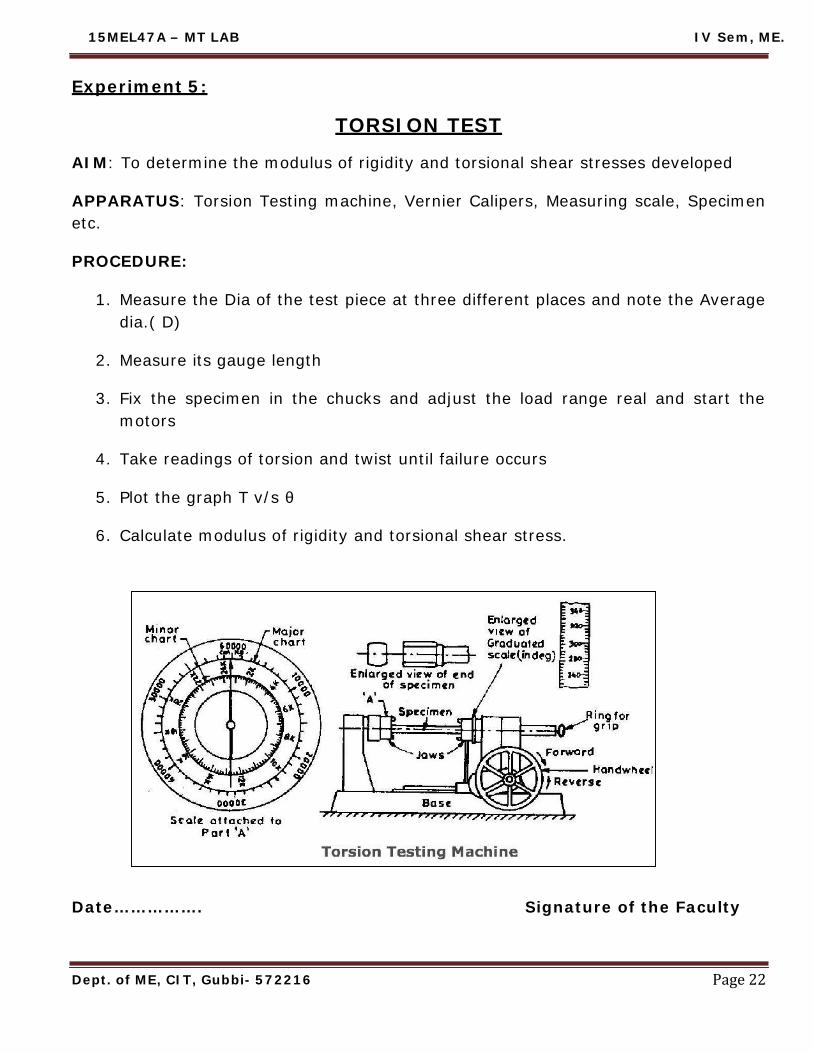
TORSION TEST
AIM: To determine the modulus of rigidity and torsional shear stresses developed
APPARATUS: Torsion Testing machine, Vernier Calipers, Measuring scale, Specimenetc.
PROCEDURE:
1. Measure the Dia of the test piece at three different places and note the Averagedia.( D)
2. Measure its gauge length
3. Fix the specimen in the chucks and adjust the load range real and start themotors
4. Take readings of torsion and twist until failure occurs
5. Plot the graph T v/s θ
6. Calculate modulus of rigidity and torsional shear stress.
Date……………. Signature of the Faculty

15MEL47A – MT LAB IV Sem, ME.
Page 23Dept. of ME, CIT, Gubbi- 572216
Fig: Izod Impact testing equipment
Fig: Position of specimen for Izod test

15MEL47A – MT LAB IV Sem, ME.
Page 24Dept. of ME, CIT, Gubbi- 572216
Experiment 6:IZOD IMPACT TEST
Objective: To determine the Impact strength (Specific impact factor) through Izod test.
Principle: Static tests are not satisfactory in determining the resistance to shock orimpact loads such as automobile parts are subjected to shock loads, and in theimpact test a notched specimen of the material is fractured by a single blow from aheavy hammer, the energy required being a measure of the resistance to impact.
Materials and equipments required
Impact testing machine, MS Specimen
Theory
IZOD Impact Test:
A pendulum type single blow impact test in which the specimen, usuallynotched, is fixed at one end and free at other end. Specimen is broken by a fallingpendulum. The energy absorbed as measured by the subsequent rise of thependulum is a measure of impact strength or notch toughness.
Notch: A slot or groove of specified characteristics intentionally cut in a test piece soas to concentrate the stress localizing the rupture.
Notch Toughness: The high resistance of the material to fracture under suddenlyapplied loads at any Stress raiser such as notch.
Toughness: The ability of the material to absorb energy and deform plasticallybefore fracture. It is usually measured by the energy absorbed in a notched impacttest like Charpy and Izod tests. The area under the stress -strain curve in a tensiletest is also a measure of toughness and as such is proportional to the combinedeffects of tensile strength and ductility.
The Izod impact energy (I) i.e, the energy required to break the specimen isobtained directly from the test. The depth below the notch and the breadth of thespecimen is measured (i.e d and b). The effective cross-sectional area below thenotch is obtained (A=bd mm2) hence, specific Impact factor=If=I/A Joules /mm2
15MEL47A – MT LAB IV Sem, ME.
Page 25Dept. of ME, CIT, Gubbi- 572216
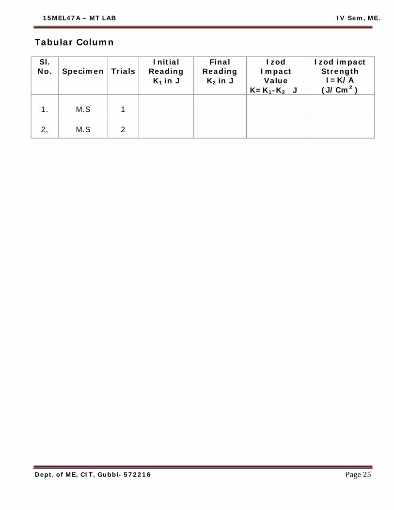
Tabular Column
Sl.No. Specimen Trials
InitialReadingK1 in J
FinalReadingK2 in J
IzodImpactValue
K=K1-K2 J
Izod impactStrengthI=K/A
(J/Cm2 )
1. M.S 1
2. M.S 2

15MEL47A – MT LAB IV Sem, ME.
Page 26Dept. of ME, CIT, Gubbi- 572216
Specification
Specimen size= 75*10*10
Type of notch = V- Notch
Angle of notch= 45o
Depth of notch= 2mm
Procedure
1. Fix the charpy striker in its respective position; place the charpy test specimenon supports.
2. Align the centre at the specimen notch with respect to centre of support bymeans of setting gauge.
3. Touch the striker to the test specimen and adjust the indicating pointer to 170J.4. Lift the pendulum till it gets latched in its position at 900 from its vertical axis.5. Allow the pendulum to swing freely and break the specimen.6. After rupture apply the break to the pendulum slowly by operating break lever.7. Note down the reading at observed energy directly on the dial as indicated by
the indicating pointer.8. Before proceeding for next test, remove the broken piece of the tested
specimen and bring indicating pointer, striker to its original position at 170J.
Results and Conclusion
Average impact value of Mild Steel = ------------Joules
Average impact strength = ------------Joules/cm2
Date……………. Signature of the Faculty

15MEL47A – MT LAB IV Sem, ME.
Page 27Dept. of ME, CIT, Gubbi- 572216
Fig: Charpy impact testing equipment
Fig: Specimen for Charpy test

15MEL47A – MT LAB IV Sem, ME.
Page 28Dept. of ME, CIT, Gubbi- 572216
Experiment 7:CHARPY TEST
Objective: To determine the Impact strength (Specific impact factor) through Charpy
test.
Principle:
The Charpy Impact Test is similar in principle to the Izod, but the notched specimenis supported at each end as a beam and struck by the hammer in the centre.
Materials and equipments required
Impact testing machine, MS Specimen
Theory
In an impact test a specially prepared notched specimen is fractured by a singleblow from a heavy hammer and energy required being a measure of resistance toImpact. Impact load is produced by a swinging of an impact weight (hammer) from aheight. Release of the weight from the height swings the weight through the arc of acircle, which strikes the specimen to fracture at the notch. Here it is interesting tonote that height through which hammer drops determines the velocity and height andmass of a hammer combined determine the energy. Energy used can be measuredfrom the scale given. The difference between potential energies is the fractureenergy. In test machine this value indicated by the pointer on the scale. This energyvalue called impact toughness or impact value, which will be measured, per unit areaat the notch.
Specification
Specimen size= 55*10*10
Type of notch = U - Notch
Angle of notch= 45o
Depth of notch= 2mm

15MEL47A – MT LAB IV Sem, ME.
Page 29Dept. of ME, CIT, Gubbi- 572216
Tabular Column
Sl.No. Specimen Trials
InitialReadingK1 in J
FinalReadingK2 in J
CharpyImpactValue
K=K1-K2 J
Charpy impactStrengthI=K/A
(J/Cm2 )
1. M.S 1
2. M.S 2

15MEL47A – MT LAB IV Sem, ME.
Page 30Dept. of ME, CIT, Gubbi- 572216
Procedure
1. Fix the charpy striker in its respective position; place the charpy test specimenon supports.
2. Align the centre at the specimen notch with respect to centre of support bymeans of setting gauge.
3. Touch the striker to the test specimen and adjust the indicating pointer to 300J.4. Lift the pendulum till it gets latched in its position at 1400 from its vertical axis.5. Allow the pendulum to swing freely and break the specimen.6. After rupture apply the break to the pendulum slowly by operating break lever.7. Note down the reading at observed energy directly on the dial as indicated by
the indicating pointer.8. Before proceeding for next test, remove the broken piece of the tested
specimen and bring indicating pointer, striker to its original position at 300J.
Results and Conclusion
Average impact value of Mild Steel = ------------JoulesAverage impact strength = ------------Joules/cm2
Date……………. Signature of the Faculty

15MEL47A – MT LAB IV Sem, ME.
Dept. of ME, CIT, Gubbi- 572216 Page 31

15MEL47A – MT LAB IV Sem, ME.
Page 32Dept. of ME, CIT, Gubbi- 572216
Experiment 8:ROCKWELL HARDNESS TEST
Objective: To determine the Rockwell hardness number of the given Specimenusing “Rockwell Hardness tester”.
Principle: A standard load (Based on type of material) is applied through astandard indentor (cone or ball indentor) for a standard duration of time. Thehardness number is directly obtained in the experiment.
Practical importance: Hardness is the property of the material by which itoffers resistance to scratch or indentation. It is the most important property, as thematerial is subjected to friction and scratch. By this experiment we can determine theHardness of the given material.
Materials and equipments required: Rockwell hardness testing machine. Diamond cone indentor, ball indentor. Specimens (Hardened steel, Mild steel, Brass, Copper, Aluminium )
Theory:Hardness of a material is generally defined as Resistance to the permanent
indentation under static and dynamic load. When a material is required to use underdirect static or dynamic loads, only indentation hardness test will be useful to find outresistance to indentation.
Rockwell test is developed by the Wilson instrument co U.S.A in 1920. This testis an indentation test used for smaller specimens and harder materials. In this testindentor is forced into the surface of a test piece in two operations, measuring thepermanent increase in depth of an indentation from the depth increased from thedepth reached under a datum load due to an additional load.
Measurement of indentation is made after removing the additional load.Indentor used is the cone having an angle of 120 degrees made of black diamond.

15MEL47A – MT LAB IV Sem, ME.
Page 33Dept. of ME, CIT, Gubbi- 572216
Observation
Type ofspecimen
Type ofIndentor Scale Total load(P)
Kg-F
Hard Metals Diamond cone C (Blackgraduations) 150
Soft Metals Ball (1/16”) B (Redgraduations ) 100
Tabular Column
Sl.No Specimen Type of
IndentorRHN Average
RHN1 2 3
01 Hardened steel Diamondcone
02 Mild steel Ball(1/16”)
03 Brass Ball(1/16”)
04 Copper Ball(1/16”)
05 Aluminium Ball(1/16”)

15MEL47A – MT LAB IV Sem, ME.
Page 34Dept. of ME, CIT, Gubbi- 572216
Specification:Rockwell hardness tester gives the direct reading of hardness number on a dialprovided with the machine. The specimen may be cylinder, cube, thick or thinmetallic sheets.Specifications are as follows.
1. Ability to determine hardness up to = 100 RHN
2. Maximum application of load = 150 Kgf
3. Method of load application = Lever type
4. least measuring hardness number= 1 RHN
Procedure:1.Keep the loading and unloading lever at position “A” which is unloading position.2. Select the suitable indentor & weights according to the scale.3. Place the specimen on testing table anvil.4. Turn the hand wheel to raise a job until it makes contact with indentor &
continue turning till the longer pointer at the dial gauge makes 2 ½ rotations.Then it stops at zero continue turning slowly till the small pointer reaches thered spot at „3‟, this is automatic zero setting dial gauge.
5. Turn the lever position „A‟ to „B‟ i.e. from unloading to loading position. So thatthe total load will act.
6. When the longer pointer of the dial gauge reaches steady position, take backthe lever to the unloading position „A‟. [Avoid sudden release at the lever]
7. Now note down the reading in the last dial indicator by notifying the largepointer
8. Turn back the hand wheel and remove the job.9. Similarly repeat the step from 1-9 for different trials and for different metals.
Results & Conclusion:Rockwell hardness Number of given specimen is
1. Hardened steel =
2. Mild steel =
3. Brass =
4. Copper =
5. Aluminium =
Date……………. Signature of the Faculty

15MEL47A – MT LAB IV Sem, ME.
Page 35Dept. of ME, CIT, Gubbi- 572216
Observation
Type ofIndentor
Totalload(P)
Kg-FSuitable for
Ball Indentor2.5mm dia. 187.5 Non ferrous soft metals, Soft iron, steel
castings, Cast iron, malleable iron.
Ball Indentor5mm dia. 250 Light alloys casting, forging alloys, die casting
alloys.
Tabular Column
Sl.No SpecimenIndentor
Diameter(D)In mm
Totalload(P)
Kg-F
Diameter ofIndentation(d)
in mmAverage
dia BHN
1 2 3
01 Mild steel
02 Brass
03 Copper
04 Aluminium

15MEL47A – MT LAB IV Sem, ME.
Page 36Dept. of ME, CIT, Gubbi- 572216
Experiment 9:BRINELL HARDNESS TEST
Objective: To determine the Brinell hardness number of the given Specimen usingBrinell hardness tester.
Principle: Brinell hardness number (BHN) is obtained by the ratio of the calculatedload and the spherical area of the Indentation or Impression made on the specimenby the corresponding Indentor Ball.
Practical importance: This Brinell Hardness Test is used to determine theHardness Number of hard, moderately hard, and soft material Eg: Brass, Bronze,Aluminum, Gold, Copper, Etc. Very hard material and Brittle material cannot betested by Brinell hardness tester.
Materials and equipments required
Brinell hardness testing machine and Brinell Microscope.
Ball Indentor of diameter 2.5mm and 5mm
Specimens ( Mild steel, Brass, Copper, Aluminium )
SpecificationIn Brinell hardness test, a steel ball of diameter (D) is forced under a load
(F) on to a surface of test specimen. Mean diameter (d) of indentation ismeasured after the removal of the load (P).
Specifications are as follows.
1. Ability to determine hardness up to =1411 BHN
2. Maximum application of load =250 Kgf
3. Method of load application = Lever type
4. least measuring hardness number= 1 BHN3

15MEL47A – MT LAB IV Sem, ME.
Page 37Dept. of ME, CIT, Gubbi- 572216
Calculations2P
Brinell Hardness Number (BHN) = D D - D2 d 2
Where,
D = Diameter of ball indentor in mmd= Diameter of Indentation in mmP= Load applied in Kgf
d=MSR+ (CVSD×LC)
Least Count of Brinell Microscope=0.01mm

15MEL47A – MT LAB IV Sem, ME.
Page 38Dept. of ME, CIT, Gubbi- 572216
Procedure1. Keep the loading and unloading lever at position “A” which is unloading
position.
2. Select the suitable indentor & weights according to the scale.
3. Place the specimen on testing table anvil.
4. Turn the hand wheel to raise a job until it makes contact with indenter &continue turning till the longer pointer at the dial gauge makes 2 ½ rotations.Then it stops at zero continue turning slowly till the small pointer reaches thered spot at „3‟, this is automatic zero setting dial gauge.
5. Turn the lever position „A‟ to „B‟ i.e. from unloading to loading position. So thatthe total load will act.
6. When the longer pointer of the dial gauge reaches steady position, take backthe lever to the unloading position „A‟. [Avoid sudden release at the lever]
7. Remove the job from the platform and note down the diameter of theindentation using Brinell microscope.
8. Using appropriate formula calculate BHN.
9. Similarly repeat the step from 1-8 for different trials and for different metals.
Results & Conclusion: Brinell hardness number of given specimen is
1. Mild steel =
2. Brass =
3. Copper =
4. Aluminium =
Conclusion: Based on BHN for Mild Steel, the Relation between the tensile strengthand Hardness Number is given as follows,
Tensile Strength of Mild Steel = K*BHN for MS
Where K= constant between 3.4 to 3.9 for types of steel.
Date……………. Signature of the Faculty

15MEL47A – MT LAB IV Sem, ME.
Page 39Dept. of ME, CIT, Gubbi- 572216
ObservationType of indentor = Diamond cone
Tabular column
Sl.No Specimen
Loadappliedin Kgf
Length of Indentation inmm(l)
Average
lengthin mm
VHN=1.854P
l 21 2 3

15MEL47A – MT LAB IV Sem, ME.
Page 40Dept. of ME, CIT, Gubbi- 572216
Experiment 10:VICKER’SHARDNESSTEST
Objective: To determine the hardness of the given Specimen using Vicker‟s hardnesstest.
Principle: The required load as calculated by P/D2 ratio is applied on the specimenfor a standard time of 8-10 Sec‟s and BHN is calculated by the ratio of load and thespherical area of indentation. The diameter of the indentation is measured on thefocusing screen of the machine.
Practical Importance :Same as in Experiment NO.8 (i.e., Rockwell Hardness Test).
Materials and equipments required:Vicker‟s Hardness Testing Machine.Diamond cone indentor,Specimen.
Theory:Very Hard materials (e.g. Mild steel, case hardened steel, etc,) can be tested by theVicker's method. If the moderately hard materials like Brass, Copper and Aluminiumare tested in this machine, the indentor makes a deep impression. Hence, a properindentation cannot be made on the specimen and a correct value of the hardnesscannot be obtained for these materials by V. H. Test.
VHN = Load Sloping or pyramidal area of indentation
This test is similar to Brinell hardness test similar relationship and eliminates most ofthe errors. A regular pyramid having a square base and smoothened off diamondpoint is pressed in the material to be tested under a load „F‟. The producedimpression is projected onto a focusing screen and the diagonals of the impressionare measured by means of the measuring equipment.Due to small impressions, it is very suitable for testing polished and hardenedmaterial surfaces. This test is rapid, accurate.

15MEL47A – MT LAB IV Sem, ME.
Page 41Dept. of ME, CIT, Gubbi- 572216
Calculations
Vicker‟s Hardness Number (VHN) =1.854P
l 2
Where,P= Load applied in Kgl= Average length of the diagonal L in mm
Least count of microscope=0.001mm1st scale each division =0.1mm2nd scale each division =0.013rd scale each division =0.001mm

15MEL47A – MT LAB IV Sem, ME.
Page 42Dept. of ME, CIT, Gubbi- 572216
Specification
1 Maximum application of load = 120 kgf2 Method of load application = Push button3 Least measuring indentation length= 0.001mm
Procedure:
1. Clean the surface at the specimen2. Fix the indentor in the hardness tester and switch on the power supply.3. Place the specimen with cleaned surface facing the indentor on the anvil at
work table.4. Focus the work piece surface for clean visibility by rotating the hand wheel at
the work table upwards and downwards.5. Select the load specified (P) push button available on the right side at the
hardness tester.6. Actuate the electric push button (Green Button) at the front for loading, the
loading lever starts moving up words and reaches the study position.7. Now release the loading lever slowly and bring it to the downward position.8. For major reading adjust the display at the indentation made by the indentor to
co inside with the micrometer on the display screen.9. For major (minor) reading adjust the movable side at the micrometer and note
down the total reading.10. The measurement is to be made for two opposite corners of the diagonal
indentation denoted as (l).11. Repeat the above procedure for different material.
Results and Conclusion: Vicker‟s hardness Number of given specimen is
1. Mild steel =
2. Hardened mild steel =
Date……………. Signature of the Faculty

15MEL47A – MT LAB IV Sem, ME.
Page 43Dept. of ME, CIT, Gubbi- 572216
MICROSTRUCTURAL STUDIES OF MATERIALS
Mild Steel High Speed Steel
Grey Cast Iron

15MEL47A – MT LAB IV Sem, ME.
Page 44Dept. of ME, CIT, Gubbi- 572216
Experiment 11:
PREPARATION OF THE SPECIMEN TO STUDY UNDERMETALLURGICAL MICROSCOPE
Introduction: The credit for originating Metallographic examination goes to Alloys Beck
Von Widmanstatten (between 1808 & 1840). Microscope was employed for the purpose in 1841, when Paul Annosow
used the instrument to examine the etched surfaces of oriental steelblades.
It was around 1890 when metallographic technique received generalrecognition, largely as a result of the work of Professor Henry C. Sorby inEngland.
Metallography is the general study of metals and their behavior, withparticular reference to their microstructure and macrostructure.
Microstructure is the characteristic appearance and physicalarrangement of metal molecules as observed with a microscope.
Macrostructure is the appearance and physical arrangement asobserved with the naked eye.
Metallurgical Microscope is by far the most important tool of themetallurgist from both the scientific and technical stand point. It helpsdetermining:
a) Grain size and shape.b) Size, shape and distribution of various phases and inclusion.c) Mechanical and thermal treatment of the alloys.
Preparation of Specimen:
Preparation of specimen is necessary to study its microstructure, because themetallurgical microscope discussed earlier makes use of the principle of reflection oflight from the specimen to obtain the final image of the metal structure. Following arethe steps involved in the preparation of specimen:1) Selection of specimen: When investigating the properties of a metal or alloy, itis essential that the specimen should be selected from that area (of the alloy plate orcasting) which can be taken as representative of the whole mass.2) Cutting of the specimen: After selecting a particular area in the whole mass, thespecimen may be removed with the help of appropriate cutting tools.

15MEL47A – MT LAB IV Sem, ME.
Page 45Dept. of ME, CIT, Gubbi- 572216
S G Iron
Aluminium Alloy Copper Alloy

15MEL47A – MT LAB IV Sem, ME.
Page 46Dept. of ME, CIT, Gubbi- 572216
3) Mounting the specimen: If the specimen is too small to be held in hand forfurther processing, it should be mounted on a thermoplastic resin disc or some otherlow melting point alloy.4) Obtaining flat specimen surface: It is first necessary to obtain a reasonably flatsurface on the specimen. This is achieved by using a fairly coarse file or machining orgrinding.5) Intermediate and Fine Grinding: Intermediate and fine grinding is carried outusing emery papers of progressively finer grade.6) Rough polishing: A very small quantity of diamond powder (particle size about 6microns) carried in a paste that is oil-soluble is placed on the nylon cloth-coveredsurface of a rotating polishing wheel. The specimen is pressed against the cloth of therotating wheel with considerable pressure and is moved around the wheel in thedirection opposite to rotation of the wheel to ensure a more uniform action.
7) Fine polishing: The polishing compound used is alumina (Al2O3) powder placedon a cloth covered rotating wheel. Distilled water is used as a lubricant. Fine polishingremoves fine scratches and very thin distorted layer remaining from the roughpolishing stage.8) Etching:Necessity-Even after fine polishing, the granular structure in a specimen usuallycannot be seen under the microscope; because grain boundaries in a metal have athickness of the order of a few atom diameters at best, and the resolving power of amicroscope is much too low to reveal their presence.
In order to make the grain boundaries visible, after polishing the metalspecimens are usually etched. Etching imparts unlike appearances to the metalconstituents and thus makes metal structure apparent under the microscope.
Method- Before etching, the polished specimen is thoroughly washed in runningwater. Then, the etching is done either by,
(i) Immersing the polished surface of the specimen in the etching reagentor by
(ii) Rubbing the polished surface gently with a cotton swab wetted withthe etching reagent.
After etching, the specimen is again washed thoroughly and dried. Now,the specimen can be studied under the microscope.
Date……………. Signature of the Faculty

15MEL47A – MT LAB IV Sem, ME.
Dept. of ME, CIT, Gubbi- 572216 Page 47

15MEL47A – MT LAB IV Sem, ME.
Experiment 12:
HEAT TREATMENT PROCESSES
In general, heat treatment can be defined as an operation, or the combination ofoperations that involve heating and cooling of a metal in solid phase to obtain certainrequired properties.
The ferrous materials can be heated to above transformation temperature andcan be heat – treated to obtain different structure.
The different heat treatment processes are based on heating the material tocertain temperature and employing different cooling rates.
In this process, heating temperature and rate of cooling adopted plays animportant role.The different processes are:
Annealing Stress-relief annealing. Process annealing. Spheroidising. Full annealing.
Normalizing Hardening Tempering
Annealing:
Annealing primarily is the process of heating a metal which is in a metastableor distorted structural state, to a temperature which will remove the instability ordistortion and then cooling it to the room temperature so that the structure is stableand/or strain free.Purpose of Annealing:
1. Removal of residual stress.2. Refining and homogenizing the structure and to give a coarse pearlite structure.3. Improving machinability.4. Improving cold working characteristics for facilitating further cold work.5. Producing desired microstructure.6. Removing residual stresses.7. Improving mechanical, physical, electrical and magnetic properties.8. Reducing hardness.
Dept. of ME, CIT, Gubbi- 572216 Page 48

15MEL47A – MT LAB IV Sem, ME.
Dept. of ME, CIT, Gubbi- 572216 Page 49

15MEL47A – MT LAB IV Sem, ME.
Normalizing:
This process involves heating the metal above the transformation temperatureup to 900º C and cooling from that temperature adopting the required rate of cooling.This process involves:
Heating the metal to around 900º C so that the metal transforms completelyinto austenite.
Holding at that temperature for some times (3minutes / mm of thickness) Cooling at a rate of 80º C to 90º C per hour up to 700ºC Then air – cooled from 700º C to room temperature.
Purpose of Normalizing:
Refining the grain structure and giving a fine pearlite structure. Producing a uniform structure. Achieving the required strength and ductility in a steel that is too soft and
ductile for machining. Improving structures in welds. In general, improving engineering properties of steels.
Hardening: (By Quenching)
Hardening is performed on metals to obtain desired hardness and structure. Itinvolves:
Heating the metal above transformation temperature, around 900ºC Holding at that temperature for 15 to 30 minutes per 25mm of cross-section. Quenching it immediately in a suitable cold medium (brine solution,
Water, oil etc.)Hardness obtained will depend upon the Composition of the material, nature andproperties of quenching medium and quenching temperature.
Properties obtained by hardening are:
Desired hardness can be obtained. Strength of material is increased. Wear resistance is increased. Martensite structure is obtained.
Dept. of ME, CIT, Gubbi- 572216 Page 50

15MEL47A – MT LAB IV Sem, ME.
Dept. of ME, CIT, Gubbi- 572216 Page 51

15MEL47A – MT LAB IV Sem, ME.
Page 52Dept. of ME, CIT, Gubbi- 572216
Tempering:
Hardening of metal produces Martensite structure with some retained austenite.The martensite structure makes the metal very hard and brittle. The retainedaustenite is unstable and it will change with time. This transformation of retainedaustenite even at room temperature leads to distortion of metal. Due to these factorsthe hardened metal cannot be used as it is. Hence tempering is carried out on themetals.
Tempering treatment involves:
Heating the metal just above Martensite structure temperature (50 O C),Holding it at that temperature for some time and then cooling either rapidly or slowly.The purpose of tempering is to remove brittleness and improve ductility in thematerial.
The Properties obtained after Tempering are:
Improvement in ductility and toughness. Slight reduction in hardness. Increase in tensile strength. Reduction in internal stress.
Date……………. Signature of the Faculty

15MEL47A – MT LAB IV Sem, ME.
Page 53Dept. of ME, CIT, Gubbi- 572216
Tabulation:
Sl.No. SpecimenMaterial
Load onPin(P) Wear
(µm)
FrictionalForce(F)
Co-efficient offriction( F/P)Kg. N Kg. N
Calculation:Frictional force (F)
Co-efficient of Friction at 40N = ……………………..Load on Pin (P)
Graph: Draw a graph of Wear Vs Load

15MEL47A – MT LAB IV Sem, ME.
Page 54Dept. of ME, CIT, Gubbi- 572216
Experiment 13:WEAR TESTING (Pin-on-disk)
Aim: To determine wear and co-efficient of friction of a standard specimenusing pin-on-disk wear testing machine.
Apparatus: Pin-on-disk wear testing machine with control unit, Weights, Alignkey, Spanner, acetone , cotton and a standard specimen pin.
Procedure:1. Clean the steel disk with acetone to free it from any debris from the
earlier usage.2. Remove the existing loads if any on the machine.3. Fix the specimen in the pin holder using align key.4. Note down the track radius.5. Apply a load of 1Kg in the Pan.6. Switch on the power of the control unit and set the timer to 5minutes.7. Set the wear and frictional force to zero.8. Start the wear testing machine and set RPM to 500.9. Note down the readings of wear and frictional force at the end of 5
minutes.10.Repeat the experiment with 2Kg, 3Kg and 4kgs.11.Tabulate the results and calculate the co-efficient of friction.12.Draw a graph of Wear (µm) Vs Load (N).
Date……………. Signature of the Faculty

15MEL47A – MT LAB IV Sem, ME.
Dept. of ME, CIT, Gubbi- 572216 Page 55

15MEL47A – MT LAB IV Sem, ME.
Experiment 14:
NON –DESTRUCTIVE TESTING
A non- destructive test is an examination of a component in any manner whichwill not impair its future use. These tests are conducted on various castings andwelded joints, to find the defects inside the castings and the welded joints, withoutbreaking them. Defects like hair – line crack, sub – surface defect, flaws, internalblow holes etc., can be determined using these techniques. Some of the non-destructive testing techniques available are:
Magnetic Particle Inspection.
Liquid (Dye) Penetrant Test. Etc.,
Ultrasonic Inspection.
Magnetic Particle inspection:Principle of Operation:
When a piece of metal is placed in a magnetic field and the lines of magnetic flux getintersected by a discontinuity, such as a crack or slag inclusion in a casting, magneticpoles are induced on either side of the discontinuity. A surface crack is indicated by aline of fine particles following the crack outline and a subsurface defect by a fuzzycollection of the magnetic particles on the surface near the discontinuity.
Technique:Procedural steps involved are: Magnetizing the component part. Applying magnetic particles on the component part. Locating the defects.
Advantages:
Magnetic particle inspection is a relatively simple and easy technique.
It is almost free from any restriction as to size, shape, composition and
heat-treatment of a ferromagnetic specimen.
Limitations:Suitable only for testing magnetic materials.
Deeper subsurface defects are not satisfactorily detected by this method of
testing.
Dept. of ME, CIT, Gubbi- 572216 Page 56

15MEL47A – MT LAB IV Sem, ME.
Dept. of ME, CIT, Gubbi- 572216 Page 57
15MEL47A – MT LAB IV Sem, ME.
Page 58Dept. of ME, CIT, Gubbi- 572216
Liquid (Dye) Penetrate Test:Principle of Operation:
The principle of liquid penetrate test is that the liquid used enter the smallopenings such as cracks or porosities by Capillary action. The rate and extent ofthis action are dependent upon such properties as surface tension, cohesion,adhesion and viscosity.
For the liquid to penetrate effectively, the surface of the material must bethoroughly cleaned of all material that would obstruct the entrance of the liquidinto the defect.
After cleaning, the liquid penetrant is applied evenly over the surface and allowedto remain long enough to permit penetration into possible discontinuities.
The liquid is then completely removed from the surface and either a wet or drydeveloper is applied. The liquid that has penetrated the defect will bleed out ontothe surface, and the developer will help delineate them.
This will show the location and general nature and magnitude of any defectpresent.
Date……………. Signature of the Faculty

15MEL47A – MT LAB IV Sem, ME.
Page 59Dept. of ME, CIT, Gubbi- 572216
TYPICAL VIVA QUESTION WITH ANSWERSDefine :
1) Homogeneity: Material should be of same type and uniformly distributed throughout the body.2) Arthotropy: Materials have different properties in different directions, e.g.orthotropic Plates.3) Isotropy: Properties is same or identical at all points in the body of the material.4) Anisotropy: Properties will not be identical at all points in the body of the material.5) Elasticity: It is the property by which the deformations caused in a body byexternal force disappears on removal of the forces. The resulting forces are with inthe elastic limit. It is determined from the tension test in graph.
6) Plasticity: It is the property by which the deformation caused in a body by externalforces do not disappear on removal of forces. We say there is permanent set inmaterial. In a tension test, the material enters the plastic region after the elasticregion is passed .
7) Ductility: Property by with the materials can be drawn into thin wires. Thepercentage elongation or contraction gives a measure of Ductility. In this case, largedeformations occur before rupture.
8) Brittleness: If the Fracture in a material occurs when the stress exceeds the elasticlimit. Tendency to break under Impact loads. It is opposite to ductility.
9) Tenacity: The property of a material to resist tension or tensile stress is calledTenacity.10) Malleability: It is the property by which the material can be beaten into sheets.E.g. Gold. Gold is the most malleable metal.
11) Rigidity: Sometimes, some materials are rigid against shear deformation. i e.they resist the deformations caused due to shear. Such property of the materials istermed as rigidity.
12) Toughness: The property of a material to-resist fracture under suddenly appliedloads is termed as Toughness. To some extent, toughness is related to impactresistance.

15MEL47A – MT LAB IV Sem, ME.
Page 60Dept. of ME, CIT, Gubbi- 572216
13) Modulus of Toughness: It is the work-done on the body in loading up to rupturepoint per unit volume or it is the area enclosed between stress-strain diagram up torupture point (see. Graph 2)
14) Resilience: It is the work done on the body in loading it up to elastic limit per unitvolume or it is the strain energy stored at elastic limit per unit volume. It is given bythe area of the stress- strain diagram upto elastic limit (ref Graph 2). It is alsotermed as "Modulus of Resilience".
Modulus of resilience = shaded area in graph 2.
15) Proof resilience or Torsional strain energy: It is the torsional S.E stored at elasticlimit per unit volume It is given by the area ofthe torque-twist diagram up to elastic limit.(Approximately, the triangular area as shown inthe figure).It is equal to = ½ TӨ where T is the torque in N.m upto elastic limit and Ө is the angle of twist inradians.
16) Stress: When a material is subjected to the

15MEL47A – MT LAB IV Sem, ME.
Page 61Dept. of ME, CIT, Gubbi- 572216
action of forces, it develops internal resistance; this Resistance Per unit area is calledthe stress.
Stress= Load N/mm2
Area
17) Strain: It is defined as ratio of change in length to original length.
Strain= Change in dimensionOriginal dimension (Unit: Dimensionless.)
18) Proof Stress: It is the stress atwhich if the material is unloaded,there will be specified percentageof strain permanently left in it.When a stress-strain curve for abrittle material subjected totension is drawn, it indicates froma graph that for such a materialthere is no definite yield point.Then to locate the approximateposition of yield or elastic limit,
stress in-percentage is plotted along y-axis and x-axis. From 0.2 % strain a line isdrawn (Shown dotted) parallel to the straight line portion of graph. From the pointwhere this line cuts the curve, the corresponding stress value is measured. This valueof stress is known as 0.2 % proof stress and the corresponding strain is termed
as .0.2 % proof strain.
19) Yield stress: Stress at which considerable elongation first occurs in the test piecewithout increase in the load. Unit: same as in stress.
20) Ultimate stress: (or Tensile Strength): The maximum load reached in a tensiontest divided by the original area of cross-section. This is also termed as maximumstress.21) Direct stress: The resistance developed in a material due to the action of directload or axial load passing through the centroidal axis of the section- is termed asdirect stress.22) Shear stress: The stress caused by forces which act parallel to an area of crosssection and tends to produce sliding of one portion past another is termed as shearstress.

15MEL47A – MT LAB IV Sem, ME.
Page 62Dept. of ME, CIT, Gubbi- 572216
23) Bending stress: It is the stress due to the applied external bending moment onthe structure.
24) Principal stress: The maximum and minimum direct or the normal stress acting ina body without shear stresses are termed as principal stresses. This can bedetermined either analytically or graphically (by Mohr's graphical method).
25) Young's Modulus of Elasticity: It is defined as the ratio of linear stress to thelinear strain or the Ratio of normal stress to the axial strain, within elastic limit.(From graph) The Young's Modulus is calculated by taking the corresponding value ofstress and strain at elastic limit from the stress- strain graph. (Unit N/mm2)
26) Tangent Modulus / Secant Modulus: It is the slope of the stress / strain diagram
at any specified point. This is used where the stress-strain diagram is not astraight line even in the initial stage. Slope of the tangent (tan Ө) = Stress/strain atany specified point. This is named as tangent modulus.
The slope of the line joining the origin of co-ordinate axis to any point on curve(p) in a load deformation curve in a compression test is called secant Modulus.
27) Modulus of Rigidity: It is defined as the ratio of shearing stress to the shearingstrain. Unit is N/mm2
28) Modulus of Rupture: It is the value of bending stress computed from the formulacorresponds to the bending movement which causes fracture of the specimen.
29) Poisson's ratio: The ratio of Lateral strain to the longitudinal strain is termed asthe Poisson‟s ratio. It is dimensionless. For most of the materials Poisson's ratio is 0.3
30) Hooke's Law: within the elastic limit, the stress is directly proportional to thestrain up to elastic limit.

15MEL47A – MT LAB IV Sem, ME.
Page 63Dept. of ME, CIT, Gubbi- 572216
31) Stiffness: The term stiffness is an indication of deformation of the body underload (load per unit deformation). It is measured by the ratio of stress & strain. If thestress is directly proportional to the strain, the stiffness is constant.
32) Stress Hardening: When a material is subjected to repeated cycle of stressesbelow fatigue limit it will exhibit higher static strength than when it is subsequentlysubjected to static tests. This is termed as stress hardening.
33) Strain Hardening: It is a phenomenon in which the mechanical properties of amaterial suddenly changes when the material changes from elastic to in-elasticrange.
34) Elasticity constants: They are the properties of materials such as Young‟sModulus, Rigidity modulus, Bulk Modulus and Poisson's Ratio.
35) Bulk modulus (K): It is the ratio of identical pressure acting in three mutuallyperpendicular directions to corresponding volumetric strain.
36) Deflection: A beam when loaded gets deflected. The axis of the loaded beambends in a curve known as the elastic curve or deflection curve. The deflection at anypoint on the axis of the beam is the vertical distance between its position beforethe load and after loading.
37) Strength: It is the maximum resistance of a material to type of loading. E.g.Flexural strength, compression strength, impact strength etc.
38) What is the usual range of carbon content in cast iron, wrought iron and Mildsteel?
What is its effect on yield and weight strengths?In M.S. carbon content is 0.3 %In C.I - 0.25 to 0.8 %In W.I -0.2%
Effect of carbon content op yield and weight strengths:As the carbon content increases, the material becomes brittle.

15MEL47A – MT LAB IV Sem, ME.
Page 64Dept. of ME, CIT, Gubbi- 572216
39) Sketch the typical failures in a tension & compression test on a ductile material
and brittle material.
40) State the reason tension test is preferred to compression test for determining themodulus of elasticity.
1. In tension test, the gauge length is quite large. Therefore strains induced areover a larger gauge length. In compression test compression specimens are short.Measurement of G.L is quite difficult. Hence the evaluation of strains is also difficult.Therefore E cannot be found out exactly in a compression test.
2. In tension test in the stress-strain curve, the elastic point is quite welldefined. Therefore Young's modulus can be exactly found out which is the ratio ofstress-strain up to elastic limit. In compression test, the elastic limit is not welldefined, as seen from graph of stress vs. strain for a material subjected tocompression. Therefore evaluation of E is not accurate in a compression test as in atension test.
41) What is Static loading and Dynamic loading as applied to hardness test?Static loading: They are the normally applied loads. They are the standardized loadsfor the Particular type of specimen. The loads are applied gradually, the initial loadbeing applied first And then the total load is finally being applied.Dynamic loading: Application of suddenly applied loads on the surface of specimento determine the hardness of metals is called dynamic loading.

15MEL47A – MT LAB IV Sem, ME.
Page 65Dept. of ME, CIT, Gubbi- 572216
42) Very hard materials cannot be tested in Brinell Hardness testing machine. Statethe reason.
For very hard materials like case hardened steel, spring steel, etc., theindentation made on the specimen in B.H. test is very small, because the standardball diameter is small equal to 2.5mm and intensity of load applied is very small. Asthe B.H. number is a function of the spherical area of indentation and load, if theindentation area is small, it greatly affects the hardness value of the material. Hence,for very hard material B.H. test is not suitable.
43) What is the purpose of applying the minor load in case of Rockwell Hardnesstest?
We should have a datum load (or a reference load) before applying the major loadon the surface of specimen so that a proper and clear indentation is made on thesurface of specimen. The datum or the reference load that is applied on specimen iscalled the minor load which is normally 10 Kg in Rockwell Hardness test. After theapplication of minor load the total major load is applied on the specimen.
44) What physical property is determined from impact test? What is its significance?The physical property determined from impact test is the resistance of a material
due to suddenly applied loads or prepared clutches. Ex. Helipad, i.e. a helicopterlanding suddenly on the Landing pad causing sudden impact, impact of a drophammer, etc.,
45) What are the types of impact tests?Two types:
a)Izod impact test: Specimen is placed as a cantilever. The type of notch will be „V‟type. The notch is facing the direction of striker of hammer.
b) Charpy Impact test Specimen is placed as a simply supported beam. The type ofnotch is „U‟ type. The notch will be facing on the opposite direction of striker ofhammer.
46) What is meant by Notch Sensitivity? Or what is the effect of notching on testspecimens.
In order to induce a fracture to occur in a ductile material under a single blow ina impact test, the specimen is generally notched. The use of notch tends to reducethe ductility causing a brittle type of fracture or the tendency of a ductile material toact like a brittle material, when broken in the form of a notched specimen is calledNotch Sensitivity.

15MEL47A – MT LAB IV Sem, ME.
Page 66Dept. of ME, CIT, Gubbi- 572216
Viva questions on MT lab
Tensile test:1. Differentiate between Engineering Stress/Strain and True Stress/Strain.2. What is meant by Plastic & Elastic Deformation?3. Define Upper Yield Point; Lower Yield Point; Ultimate Strength; Fracture
Strength.4. What is meant by Gauge Length?5. What are the various types of fractures?6. Differentiate between Brittleness and ductility?7. Define the term Malleability?8. What is Strain hardening?9. How the microstructural defect like slip effects the deformation?
Compressive strength test:1. Differentiate between Compressive strength and tensile strength.2. Describe the fracture mechanism of a material under compressive loading.3. Theoretically compressive strength should be same as the tensile strength of a
material, but practically it is not. Why?4. What is anisotropy? How does it effect the mechanical properties?
Modulus of rigidity:1. What is meant by modulus of rigidity?2. Define torsion strength.3. What are the factors which may affect the angle of twist?4. What will be the effect on strength if a solid circular shaft is replaced by a
hallow shaft of same dimension.5. What is meant by strain energy? Give its expression in torsion for solid and
hollow circular shaft.6. What is Poisson‟s Ratio?
Impact test:1. What is meant by toughness?2. What is the purpose of V-notch in impact testing and what is its dimension?3. What is resilience?4. How does tempering changes the toughness of a material?5. Define Notch Impact Strength & Modulus of Rupture.6. Differentiate between Izod & Charpy impact testing techniques?

15MEL47A – MT LAB IV Sem, ME.
Page 67Dept. of ME, CIT, Gubbi- 572216
Young’s modulus:1. What is Young’s Modulus?2. What is meant by Moment of Inertia?3. How to find out the least count of vernier caliper.4. What is the effect of temperature on Young’s Modulus?5. How will you define a “beam‟?6. What is the difference between a simple supported beam & cantilever beam?7. What is the formula used to calculate the Moment of Inertia of a Square section
beam; Rectangular section beam and a circular beam about the axis.8. What is meant by Polar Moment of Inertia & how is it calculated?9. Derive the relationship between Young’s Modulus, Modulus of Rigidity & Bulk
Modulus.10. Describe different types of loads on beam with the help of sketches
Heat Treatment:
1. What is meant by heat treatment?2. What are the different types of heat treatment?3. Enumerate the need for heat treatment of steel?4. List different types of hardness testing methods?5. What is meant by BHN?6. Differentiate between hardenability and hardness?7. What are the different types of indenters used in hardness testing?8. What are the factors which effect the hardness of steels?9. Why is the minor load applied before applying the major load?10. Derive the formula to calculate BHN.
Microstructures:
1. Why the microstructures of metals are different from each other?2. What are the effects of microstructure of steel and CI on their mechanical
properties?3. In which way is the microstructure of copper different from the
microstructure of brass?4. Define Pearlite, Austenite, Ferrite, Cementite, Martensite, Bainite, and
Ledeburite.5. What is the purpose of alloying? Describe few alloys of Copper and Aluminium.6. How are steels classified based on their alloying (carbon) content?

15MEL47A – MT LAB IV Sem, ME.
Page 68Dept. of ME, CIT, Gubbi- 572216
7. What is Cast Iron? What are its types?8. What are stainless steels? Give its composition.9. Discuss in brief, the steel manufacturing process.10.Discuss the properties and manufacturing process of the following:Composites; Ceramics; Plastics and Glass.11.What are the specifications of grinding and polishing machines?12.What is lapping? Which degree of accuracy can be achieved in metals by
polishing?13.Why is grinding performed before polishing?14.What is the need of polishing on four grades of emery paper?15.Why is the specimen rotated by 90°, while changing from one grade of emery
paper to another?16.Why is dry polishing done before wet polishing?17.What is the purpose of wet polishing after dry polishing?18.Why is alumina powder used in wet polishing?19.What is the purpose of etching?20.Which etchant is used for etching MS; aluminium; copper?21.What is the principle of working of metallurgical microscope?

15MEL47A – MT LAB IV Sem, ME.
Page 69Dept. of ME, CIT, Gubbi- 572216
(Beyond the syllabus experiment)EXPERIMENT 01:
TENSILE TEST ON POLYMERIC COMPOSITES
AIM: To determine UTS of glass fiber composite specimen.
Objective: To study the behavior of the given material under tensile load and todetermine the Ultimate tensile strength
Ultimate stress or Maximum tensile stress Breaking stress or Failure stress
Practical importance: While designing a component, selection of materials forlightweight applications in automobile industries, etc., is very important. Differentapplications is based on ultimate strength of different polymer materials. Therefore,from this tension test above said strength can be calculated.
Apparatus Required:Universal Testing machine, Dial gauge, Vernier caliper and scale.
Theory:In engineering, tension test is widely used to provide basic design information on thestrength of the materials. In the tension test a specimen is subjected to a continuallyincreasing uniaxial tensile force while simultaneous observations are made of theelongation of the specimen and the UTS of the specimen material is determined. Astress-strain curve is plotted from the load-elongation measurements.
Procedure: The original dimensions of the specimen like original length, gauge length
etc. is to be measured. The specimen is mounted and gripped in the Universal Testing machine
between the fixed and movable jaws. The load range in the machine is adjusted to its maximum capacity (600
kN) The dial gauge is mounted on the machine at the appropriate positions and
adjusted to zero. The machine is switched on and the tensile load is applied gradually. The specimen is loaded continuously up to the ultimate load. With further loading the specimen breaks, and breaking load is noted.

15MEL47A – MT LAB IV Sem, ME.
Page 70Dept. of ME, CIT, Gubbi- 572216
Observations1. Least count of dial gauge = 0.01mm.
2. Specimen Material = …………………
3. Initial length (li) = ………….. ….. mm
6. Ultimate Load (pu ) =…………KN
i. Where „pu‟ is the maximum load applied.
7. Final length (lf) =……………….mm
Tabular Column:
Sl.No. Load in
KN
Load in
NStress inN/mm2
StrainUTS inN/mm2
Young’smodulusN/mm2
1
E = stressstrain
Resultfrom
the graph
23456789
101112131415
Result: The ultimate strength of the glass fiber polymer composite material is…………………