lab on a chip - labs. · pdf file27-01-2018 · lab on a chip paper cite this: doi:...
TRANSCRIPT
Lab on a Chip
PAPER
Cite this: DOI: 10.1039/c8lc00098k
Received 27th January 2018,Accepted 5th March 2018
DOI: 10.1039/c8lc00098k
rsc.li/loc
Biodegradable 3D printed polymer microneedlesfor transdermal drug delivery†
Michael A. Luzuriaga, a Danielle R. Berry, a John C. Reagan,b
Ronald A. Smaldone *a and Jeremiah J. Gassensmith *ab
Biodegradable polymer microneedle (MN) arrays are an emerging class of transdermal drug delivery de-
vices that promise a painless and sanitary alternative to syringes; however, prototyping bespoke needle ar-
chitectures is expensive and requires production of new master templates. Here, we present a new micro-
fabrication technique for MNs using fused deposition modeling (FDM) 3D printing using polylactic acid, an
FDA approved, renewable, biodegradable, thermoplastic material. We show how this natural degradability
can be exploited to overcome a key challenge of FDM 3D printing, in particular the low resolution of these
printers. We improved the feature size of the printed parts significantly by developing a post fabrication
chemical etching protocol, which allowed us to access tip sizes as small as 1 μm. With 3D modeling soft-
ware, various MN shapes were designed and printed rapidly with custom needle density, length, and shape.
Scanning electron microscopy confirmed that our method resulted in needle tip sizes in the range of 1–55
μm, which could successfully penetrate and break off into porcine skin. We have also shown that these
MNs have comparable mechanical strengths to currently fabricated MNs and we further demonstrated
how the swellability of PLA can be exploited to load small molecule drugs and how its degradability in skin
can release those small molecules over time.
Introduction
Hypodermic needles have been used clinically for more than150 years and are the most common drug delivery devices. Al-though effective, hypodermic needles cause pain, elicit pho-bias in patients, require training and generate biohazardouswaste.1,2 Polymer microneedle (MN) arrays are flexible pat-terned grids of sharp micron-sized protrusions capable of de-livering therapeutic agents into the skin and are notably pain-free. MNs have gained attention in recent years as a mini-mally invasive and cost effective method to enhance drugdelivery.3–5 In an array, polymer MNs can act as a passivedrug delivery system with the potential to improve drug effi-cacy owing to several intrinsic advantages: namely they (i) canelicit a higher immunogenic response,6–10 (ii) inhibit micro-bial entrance at the injection site,11 (iii) can be administeredat home by unskilled caregivers,12,13 (iv) have the capacity toimprove the shelf life of drugs,14–16 (v) have the capability forhigh loading capacity,17,18 and (vi) have flexibility in material
composition that permits smart drug delivery systems.19–22
This flexibility means polymer MN arrays can be tailored tothe therapeutic used and the intended application using dif-ferent MN architectures. At their most basic, microneedlesare used to perforate skin to permit faster passive diffusion ofa topically applied drug directly into the dermis. More com-plex architectures have been discussed in several excellent ar-ticles and reviews23–32 though the most common architecturesin literature either involve coating drug onto the surface ofthe MNs to allow instant dosing upon tissue penetration ortrapping both small- and large-molecular weight agents33,34
within the polymeric matrix of the MNs. In these latter formu-lations, the MNs can be broken off into the skin and the grad-ual dissolution of the needle within the skin concomitantlyreleases drug.
Fabrication of these polymeric MNs is typically accom-plished with a micromolding process that enables the use ofthe mold several times.35 This process typically involves crea-tion of a single master template, which is then used to castall the subsequent MNs.36 Although template driven fabrica-tion has precise control over shape and size, the startup costsassociated with it are high. Template fabrication is generallycomplicated, needs a controlled environment of low particles,and requires expensive photolithography and etching equip-ment.37 Template fabrication becomes problematic when anymodification becomes necessary to the MN. This is
Lab ChipThis journal is © The Royal Society of Chemistry 2018
aDepartment of Chemistry and Biochemistry, University of Texas at Dallas, 800
West Campbell Road, Richardson, TX 75080-3021, USA.
E-mail: [email protected], [email protected] of Bioengineering, University of Texas at Dallas, 800 West Campbell
Road, Richardson, TX 75080-3021, USA
† Electronic supplementary information (ESI) available. See DOI: 10.1039/c8lc00098k
Publ
ishe
d on
07
Mar
ch 2
018.
Dow
nloa
ded
by U
nive
rsity
of
Tex
as S
outh
wes
tern
Med
ical
Cen
ter
on 1
5/03
/201
8 20
:07:
20. View Article Online
View Journal
Lab Chip This journal is © The Royal Society of Chemistry 2018
acceptable for designs that are ready for mass production,but is expensive for screening new designs. Alternativemethods to photolithography have been reported to add flexi-bility and productivity such as two photon polymerization38
and bulk micromachining.39 However, these methods are stillconsidered to be time consuming and expensive in the pro-duction of prototype MNs.
Additive manufacturing, more commonly known as 3Dprinting, is a method of fabricating physical parts from a dig-ital model generated using computer aided design softwareby adding materials layer by layer.40 The 3D printer's abilityto allow users to produce objects on demand has proven use-ful in construction,41 automotive42 and aerospacemanufuacturing,43 and biomedical applications.44,45 Scien-tists are beginning to implement 3D printing in the researchlaboratory as a tool for rapid prototyping,46–48 device fabrica-tion,49 self-healing polymers for improved mechanicalstrength,50–52 and developing scaffolds for tissue engineer-ing.53,54 3D printers commonly used for printing plastic ma-terials include fused deposition modeling (FDM),51,55–57 se-lective laser sintering (SLS),58,59 and stereolithography(SLA).58,60 SLS and SLA printers are capable of producing fea-tures smaller than 100 μm, however, these printers can becostly61 and most materials are not biocompatible. For in-stance, the photo-initiators required in the SLA printing pro-cess are toxic and are incompatible for transdermal drugdelivery.62–64
FDM is versatile, cost effective, and can print renewableand biodegradable materials, such as polylactic acid (PLA)and polyvinyl alcohol, which are approved by the Food andDrug Administration (FDA) for use in dissolvable stitches.65
However, a major limitation is that the resolution of FDM is
lower than other printing methods and generally incapableof making fine structures like MNs. Studies comparing hypo-dermic needles and MNs have been conducted and the opti-mal length, width, thickness, and the number of MNs in anarray that cause pain in humans have been determined.66,67
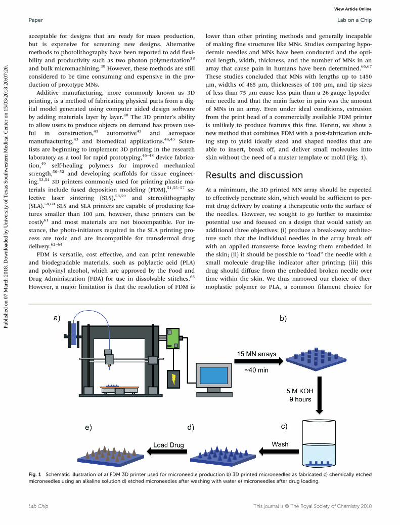
These studies concluded that MNs with lengths up to 1450μm, widths of 465 μm, thicknesses of 100 μm, and tip sizesof less than 75 μm cause less pain than a 26-gauge hypoder-mic needle and that the main factor in pain was the amountof MNs in an array. Even under ideal conditions, extrusionfrom the print head of a commercially available FDM printeris unlikely to produce features this fine. Herein, we show anew method that combines FDM with a post-fabrication etch-ing step to yield ideally sized and shaped needles that areable to insert, break off, and deliver small molecules intoskin without the need of a master template or mold (Fig. 1).
Results and discussion
At a minimum, the 3D printed MN array should be expectedto effectively penetrate skin, which would be sufficient to per-mit drug delivery by coating a therapeutic onto the surface ofthe needles. However, we sought to go further to maximizepotential use and focused on a design that would satisfy anadditional three objectives: (i) produce a break-away architec-ture such that the individual needles in the array break offwith an applied transverse force leaving them embedded inthe skin; (ii) it should be possible to “load” the needle with asmall molecule drug-like indicator after printing; (iii) thisdrug should diffuse from the embedded broken needle overtime within the skin. We thus narrowed our choice of ther-moplastic polymer to PLA, a common filament choice for
Fig. 1 Schematic illustration of a) FDM 3D printer used for microneedle production b) 3D printed microneedles as fabricated c) chemically etchedmicroneedles using an alkaline solution d) etched microneedles after washing with water e) microneedles after drug loading.
Lab on a ChipPaper
Publ
ishe
d on
07
Mar
ch 2
018.
Dow
nloa
ded
by U
nive
rsity
of
Tex
as S
outh
wes
tern
Med
ical
Cen
ter
on 1
5/03
/201
8 20
:07:
20.
View Article Online
Lab ChipThis journal is © The Royal Society of Chemistry 2018
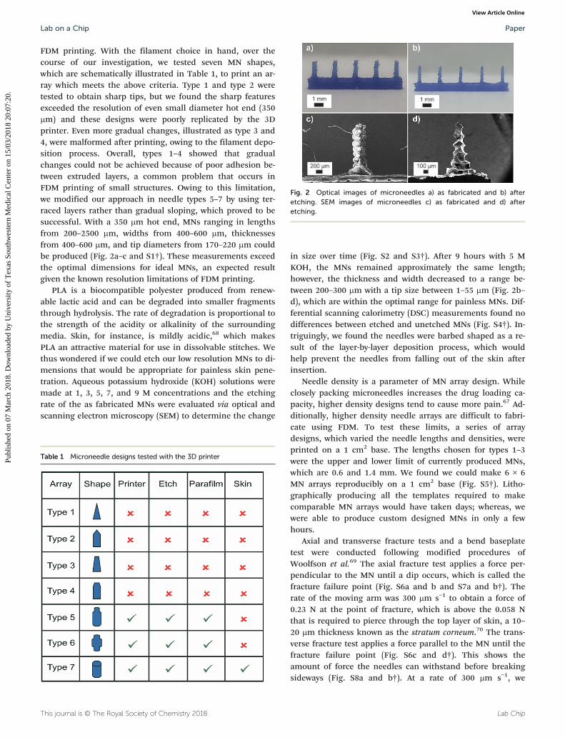
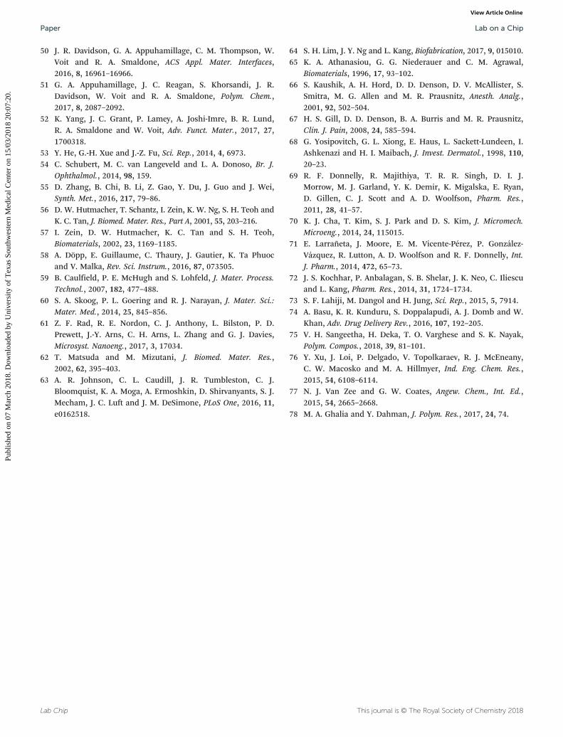
FDM printing. With the filament choice in hand, over thecourse of our investigation, we tested seven MN shapes,which are schematically illustrated in Table 1, to print an ar-ray which meets the above criteria. Type 1 and type 2 weretested to obtain sharp tips, but we found the sharp featuresexceeded the resolution of even small diameter hot end (350μm) and these designs were poorly replicated by the 3Dprinter. Even more gradual changes, illustrated as type 3 and4, were malformed after printing, owing to the filament depo-sition process. Overall, types 1–4 showed that gradualchanges could not be achieved because of poor adhesion be-tween extruded layers, a common problem that occurs inFDM printing of small structures. Owing to this limitation,we modified our approach in needle types 5–7 by using ter-raced layers rather than gradual sloping, which proved to besuccessful. With a 350 μm hot end, MNs ranging in lengthsfrom 200–2500 μm, widths from 400–600 μm, thicknessesfrom 400–600 μm, and tip diameters from 170–220 μm couldbe produced (Fig. 2a–c and S1†). These measurements exceedthe optimal dimensions for ideal MNs, an expected resultgiven the known resolution limitations of FDM printing.
PLA is a biocompatible polyester produced from renew-able lactic acid and can be degraded into smaller fragmentsthrough hydrolysis. The rate of degradation is proportional tothe strength of the acidity or alkalinity of the surroundingmedia. Skin, for instance, is mildly acidic,68 which makesPLA an attractive material for use in dissolvable stitches. Wethus wondered if we could etch our low resolution MNs to di-mensions that would be appropriate for painless skin pene-tration. Aqueous potassium hydroxide (KOH) solutions weremade at 1, 3, 5, 7, and 9 M concentrations and the etchingrate of the as fabricated MNs were evaluated via optical andscanning electron microscopy (SEM) to determine the change
in size over time (Fig. S2 and S3†). After 9 hours with 5 MKOH, the MNs remained approximately the same length;however, the thickness and width decreased to a range be-tween 200–300 μm with a tip size between 1–55 μm (Fig. 2b–d), which are within the optimal range for painless MNs. Dif-ferential scanning calorimetry (DSC) measurements found nodifferences between etched and unetched MNs (Fig. S4†). In-triguingly, we found the needles were barbed shaped as a re-sult of the layer-by-layer deposition process, which wouldhelp prevent the needles from falling out of the skin afterinsertion.
Needle density is a parameter of MN array design. Whileclosely packing microneedles increases the drug loading ca-pacity, higher density designs tend to cause more pain.67 Ad-ditionally, higher density needle arrays are difficult to fabri-cate using FDM. To test these limits, a series of arraydesigns, which varied the needle lengths and densities, wereprinted on a 1 cm2 base. The lengths chosen for types 1–3were the upper and lower limit of currently produced MNs,which are 0.6 and 1.4 mm. We found we could make 6 × 6MN arrays reproducibly on a 1 cm2 base (Fig. S5†). Litho-graphically producing all the templates required to makecomparable MN arrays would have taken days; whereas, wewere able to produce custom designed MNs in only a fewhours.
Axial and transverse fracture tests and a bend baseplatetest were conducted following modified procedures ofWoolfson et al.69 The axial fracture test applies a force per-pendicular to the MN until a dip occurs, which is called thefracture failure point (Fig. S6a and b and S7a and b†). Therate of the moving arm was 300 μm s−1 to obtain a force of0.23 N at the point of fracture, which is above the 0.058 Nthat is required to pierce through the top layer of skin, a 10–20 μm thickness known as the stratum corneum.70 The trans-verse fracture test applies a force parallel to the MN until thefracture failure point (Fig. S6c and d†). This shows theamount of force the needles can withstand before breakingsideways (Fig. S8a and b†). At a rate of 300 μm s−1, we
Table 1 Microneedle designs tested with the 3D printer
Fig. 2 Optical images of microneedles a) as fabricated and b) afteretching. SEM images of microneedles c) as fabricated and d) afteretching.
Lab on a Chip Paper
Publ
ishe
d on
07
Mar
ch 2
018.
Dow
nloa
ded
by U
nive
rsity
of
Tex
as S
outh
wes
tern
Med
ical
Cen
ter
on 1
5/03
/201
8 20
:07:
20.
View Article Online

Lab Chip This journal is © The Royal Society of Chemistry 2018
obtained 0.64 N for our etched MNs. These results, in combi-nation with the DSC, shows that etching the needles does notaffect the mechanical and material properties of PLA—simi-lar to currently fabricated MNs.35,70 All needles fractured ineach test were verified optically and these results are tabu-lated in Table S1.† Because FDM prints layers of plastic, wecan easily adjust the thickness—and presumably the flexibil-ity—of the base by changing the number of printed layers(Fig. S9†). To that end, a base plate test was conducted forbases produced with two, three, and four layers of PLA (TableS2†). We obtained 15.6° for the four layers before the basebroke in half (Fig. S10†). This is far more flexible thanreported69 values of bases made from polyIJlactic-co-glycolic)acid using conventional molds, which break at 1.28°. Theflexibility allows the MN array to easily deform when appliedto any surface on the body.
The performance of the etched MNs in transdermal drugdelivery was evaluated via penetration and staining test. Weinitially tested penetration on a 1.8 mm thick sheet of para-film, which has been shown to mimic the mechanical proper-ties of skin.71 Etched MN arrays 1.4 mm in length wereinserted perpendicular into the parafilm and were broken offby applying transverse force after insertion with a successrate of 92% (Fig. 3a). In other words, 92% of the needles onthe array successfully pierced the parafilm and remained im-bedded in the film following transverse pressure to breakthem off. This was further tested with MNs with lengths of0.6, 1.0, and 1.2 mm. Similar results were obtained for 1.2mm needles, however, 0.6 mm and 1.0 mm failed to breakoff. While useful for mechanical testing, parafilm does notmimic the physiological environment of skin and not ade-quate to measure drug diffusion.
Porcine skin was used as a physiological mimic of humanskin and was cut into 3 × 3 cm slabs. The insertion of MNs
1.4 mm in length into porcine skin, followed by applicationof transverse force resulted in 84% of the needles breakingaway from the array and remaining embedded in the tissue.This was also tested with the shorter length MNs, which dem-onstrated penetration but again did not break-off with trans-verse force. These results are in line with published dissolv-able MNs made via photolithography (Fig. 3b and c).72,73
Cross-sectional measurements at the location of insertion ofthe 1.4 mm MNs confirmed insertion and showed depths upto 250 μm (Fig. 3d).
A key quality of these needles is that they can be used assolid, coated, or dissolvable MNs. Drugs can be loaded bycoating the needles or encapsulation within the polymer ma-trix. To assess our etched MNs for drug delivery by coatingwe used methylene blue, followed by insertion into porcineskin. The MNs remained in the porcine skin to allow the ab-sorption of methylene blue to diffuse into the tissue and wereremoved after 30 s. The tissue was then optically imaged(Fig. 3e and f) and the expected transfer of methylene bluewas seen in the perforated tissue.
While coated MNs are easy to prepare, drug loading is lim-ited and release rates are difficult to control. A more sophisti-cated architecture to control drug release and improve load-ing is to absorb drugs into the polymeric matrix of adissolvable MN array. Previous results65 have shown that PLAsutures degrade in physiological environments. It stands toreason that small molecules embedded in polymer matrixshould be released as the PLA MNs dissolve. To load ourdrug-like molecule—we used fluorescein in these tests—weidentified solvents capable of swelling, but not dissolvingPLA. To load our needles, arrays were soaked in an acetonesolution containing 2 mg mL−1 of fluorescein for 1 h. Acetonewas then removed from the MN arrays by evaporation for 30min under dynamic vacuum (Fig. S11†). We tested drug
Fig. 3 Fracture test of microneedles a) in parafilm, b) in porcine skin, c) zoomed in image of porcine skin, and d) cross-section image indicatingneedle penetration depth in porcine skin. The solid line represents the end of the stratum corneum. Penetration test of microneedles e) to demon-strate the diffusion of methylene blue in the porcine skin and f) close up image of a single puncture showing delivery in the surrounding tissue.
Lab on a ChipPaper
Publ
ishe
d on
07
Mar
ch 2
018.
Dow
nloa
ded
by U
nive
rsity
of
Tex
as S
outh
wes
tern
Med
ical
Cen
ter
on 1
5/03
/201
8 20
:07:
20.
View Article Online

Lab ChipThis journal is © The Royal Society of Chemistry 2018
release under pH conditions representative of those found inthe skin. Our general procedure involved submerging 100 in-dividual MNs (equivalent to four MN arrays) in sodium ace-tate/acetic acid buffer solution (pH 4.0) to simulate needlesbroken off into the skin. The release of fluorescein was moni-tored by UV-vis spectroscopy (Fig. 4a) for 36 hours and thedrug concentrations per MN array were calculated using theBeer–Lambert law (Fig. S12†). We have demonstrated that3.23 μg of the model drug can be delivered from 25 needles(a single MN array, Fig. 4b and c and S13†), with 50% drugrelease occurring after approximately 4 h.
Fluorescent MN arrays were inserted into porcine skinsamples to visualize release and diffusion over time (Fig. 5).Shortly after insertion, fluorescein was localized at the site ofpenetration (Fig. 5a) and over time the fluorescein began todiffuse as seen in Fig. 5b–d. It should be noted that after 12h further diffusion of fluorescein was minimal as approxi-mately 80% had been released. Cross-sections of porcinesamples at the site of insertion were imaged to determine theextent of fluorescein diffusion over time (Fig. 5e–h). Asexpected, the fluorescein diffused evenly throughout the por-
cine skin as time progressed. This diffusion behaviour ver-ifies the MNs ability to penetrate past the stratum corneumand facilitate passive drug delivery.
Conclusions
In summary, we have developed a new chemical etchingmethod that improves the feature size resolution of FDMprinted materials allowing for the fabrication of biocompati-ble MNs capable of penetrating the outer layers of skin anddelivering a model therapeutic agent. We have shown thatprinting parameters can easily be tuned to develop MNs ofvarying shapes, lengths, and array densities without theneed of a master template. While PLA, a polyester derivedfrom renewable monomers, is a common filament choicefor FDM printing, other polyesters have been investigatedfor uses in tissue engineering,74 blends to enhanceproperties,75–77 and other medical applications.78 Further-more, FDM is compatible with other biorenewable thermo-plastic materials that are FDA approved such as polyglycolicacid, polycaprolactone, and polyIJlactic-co-glycolic) acid. Usingour etching method, all of these biocompatible polyesters—which currently cannot be used with higher resolution print-ing techniques such as SLA—could now be applied in MNfabrication. Future work involves improving the FDM 3Dprinter's nozzle design to enhance the resolution withoutraising the cost significantly or developing a technique thatwill allow for more versatile MNs. By enhancing the resolu-tion, more defined shapes can be made, which would lowerthe amount of time needed for etching. With the advance-ment of 3D printing in industry, particularly recent commer-cial launches of 3D printed products, this method providesa scalable fabrication of MNs. This novel fabrication methodhas demonstrated the potential of rapid prototyping MNs atlow costs, bridging the gap between additive manufacturingand passive drug delivery.
Fig. 5 Images of porcine samples inserted with loaded microneedles a) after initial insertion, b) 4 h, c) 12 h, and d) 36 h. Images of cross-sectionsof porcine samples e) after initial insertion, f) 4 h, g) 12 h, and h) 36 h. All images were illuminated by a 15 W UV (365 nm) light.
Fig. 4 The release of microneedles containing fluorescein in asolution of buffer at pH 4 a) monitored over 36 h b) fluorescentmicroneedles under UV light (365 nm) c) loaded microneedles aftersolvent removal.
Lab on a Chip Paper
Publ
ishe
d on
07
Mar
ch 2
018.
Dow
nloa
ded
by U
nive
rsity
of
Tex
as S
outh
wes
tern
Med
ical
Cen
ter
on 1
5/03
/201
8 20
:07:
20.
View Article Online

Lab Chip This journal is © The Royal Society of Chemistry 2018
ExperimentalMaterials
Fluorescein, acetone, and potassium hydroxide were pur-chased from Sigma Aldrich or Fisher Scientifics and used asreceived without further purification. Porcine skin was pur-chased from Sierra for Medical Science. Polylactic acid fila-ment was purchased from SUNLU.
Fabrication of 3D printed microneedles
Types 1–7 MNs were designed using the Blender softwarepackage and fabricated using a LulzBot TAZ 5 3D printer(Aleph Object, Inc., Loveland, CO) with 3.0 mm PLA filament(Zhunhai Sunlu Industrial Co., LTD). The printer was oper-ated with the Cura software package for LulzBot. The printingparameters used to fabricate MNs are as such: print speed:50 mm s−1, layer height: 0.2 mm, shell thickness: 0.30 mm,retraction speed: 10 mm s−1, travel speed: 175 mm s−1, bot-tom layer speed: 15 mm s−1, infill speed: 30 mm s−1, top/bot-tom speed: 20 mm s−1, outer shell speed: 20 mm s−1, and in-ner shell speed: 20 mm s−1. The temperature of the hot endwas set at 195 °C, and the temperature of the print bed wasset to 60 °C. A print head with a 0.35 mm nozzle diameterwas used.
Microneedle array etching and loading
As fabricated MNs made from PLA were placed in a 5 M KOHbath for 4 h, such that only the needle tips were submerged.After 4 h, the MN arrays were completely immersed for an ad-ditional 5 h followed by several washes with water to removethe KOH solution. To load fluorescein, etched MN arrayswere immersed in an acetone solution containing fluorescein(2 mg mL−1) for 1 h. Acetone was then removed from the MNarrays by evaporation for 30 min under dynamic vacuum.
Mechanical testing of MN arrays
All mechanical properties were performed on a Instron 5848Micro Tester (Illinois Tool Works, Inc, Norwood, MA). Themoving arm in all test moved at 300 μm s−1. For axial fracturetest, MNs were placed directly on the loading cell and a cylin-drical probe was used to apply an axial force. For the trans-verse fracture test, an aluminium block was used (Fig. S9 andS10†). The backing layer of the MN array was attached withethyl cyanoacrylate super glue gel (Harbor Freight Tools,Caramillo, CA). A metal probe with a 1 cm blunt end wasused to apply a transverse force on the needle. For bend test,two aluminium blocks were used to hold the MN array abovethe loading cell (Fig. S10†). The probe was then used to applyforce on the center of the backing layer.
Porcine skin cargo delivery tests
Porcine skin (Sierra for Medical Science) was cut into 3 × 3cm slabs and nailed to a wooden block. For needle fracturetesting, etched MNs were inserted perpendicular to the por-cine skin and transverse force was applied until needle frac-
ture occurred. To test the delivery of cargo that was coatedonto the MNs, methylene blue was applied on the needles.Tweezers were used to hold the backing layer to submergeonly the needle tips into the dye. The coated needles werethen inserted into porcine skin for 30 s, and delivery intoporcine skin was verified with an optical microscope(AmScope SE306R-PZ). To test the diffusion rate and efficacyof fluorescein from the MNs into porcine skin tissue, the MNarrays were inserted into to the porcine skin and removed af-ter initial insertion, 4, 12, and 36 h under ambient conditionswithout shearing the needles. Images were taken under ambi-ent and ultraviolet light (365 nm).
Characterization
All MNs were imaged using scanning electron microscopy(SEM, LEO, 1530, Zeiss) with an accelerating voltage of 2.5kV. To enhance the conductivity, the samples were treatedwith gold sputtering method prior to microscopecharacterization.
UV-vis drug release tests were performed using a Cary5000 UV-vis-NIR spectrophotometer (Agilent, Santa Clara,CA). MNs loaded with fluorescein were removed from thebase of four MN arrays (100 needles) and placed into a quartzcuvette with a 1 cm path length. The cuvette was filled withsodium acetate/acetic acid buffer (3.3 mL, pH 4) and mea-sured in 1 h intervals for 36 h. The samples were agitated be-fore each measurement for the first 6 h.
Author contribution
All authors have given approval to the final version of themanuscript M. A. L., R. A. S., and J. J. G. designed andconducted the experiments; M. A. L. and J. C. R. optimizedparameters for the 3D printed microneedles; M. A. L. devel-oped etching protocol, took SEM images, performed the me-chanical properties, and time studies of fluorescein diffusioninto porcine skin; M. A. L. and D. R. B. did porcine inser-tions; D. R. B. loaded microneedles with fluorescein andconducted the kinetics studies.
Conflicts of interest
There are no conflicts to declare.
Acknowledgements
R. A. S. acknowledges support from the Department ofEnergy's Kansas City National Security Campus, which is op-erated and managed by Honeywell FM&T, LLC, for the Na-tional Nuclear Security Administration. J. J. G. acknowledgesthe National Science Foundation (DMR-1654405) forfunding.
References
1 B. Deacon and J. Abramowitz, J. Anxiety Disord., 2006, 20,946–960.
Lab on a ChipPaper
Publ
ishe
d on
07
Mar
ch 2
018.
Dow
nloa
ded
by U
nive
rsity
of
Tex
as S
outh
wes
tern
Med
ical
Cen
ter
on 1
5/03
/201
8 20
:07:
20.
View Article Online

Lab ChipThis journal is © The Royal Society of Chemistry 2018
2 R. Hanas, Pediatr. Diabetes, 2004, 5, 102–111.3 S. Henry, D. V. McAllister, M. G. Allen and M. R. Prausnitz,
J. Pharm. Sci., 1998, 87, 922–925.4 R. F. Donnelly, T. R. R. Singh and A. D. Woolfson, Drug
Delivery, 2010, 17, 187–207.5 P. Ghosh, N. K. Brogden and A. L. Stinchcomb, J. Pharm.
Sci., 2014, 103, 652–660.6 H.-W. Yang, L. Ye, X. D. Guo, C. Yang, R. W. Compans and
M. R. Prausnitz, Adv. Healthcare Mater., 2017, 6, 1600750.7 J. M. Arya, K. Dewitt, M. Scott-Garrard, Y.-W. Chiang and
M. R. Prausnitz, J. Controlled Release, 2016, 239, 19–26.8 P. C. DeMuth, A. V. Li, P. Abbink, J. Liu, H. Li, K. A. Stanley,
K. M. Smith, C. L. Lavine, M. S. Seaman, J. A. Kramer, A. D.Miller, W. Abraham, H. Suh, J. Elkhader, P. T. Hammond,D. H. Barouch and D. J. Irvine, Nat. Biotechnol., 2013, 31,1082–1085.
9 Z. Zhu, X. Ye, Z. Ku, Q. Liu, C. Shen, H. Luo, H. Luan, C.Zhang, S. Tian, C. Lim, Z. Huang and H. Wang, J. ControlledRelease, 2016, 243, 291–302.
10 A. K. Shakya, C. H. Lee and H. S. Gill, J. Controlled Release,2017, 265, 75–82.
11 R. F. Donnelly, T. R. R. Singh, M. M. Tunney, D. I. J.Morrow, P. A. McCarron, C. O'Mahony and A. D. Woolfson,Pharm. Res., 2009, 26, 2513–2522.
12 R. F. Donnelly, K. Moffatt, A. Z. Alkilani, E. M. Vicente-Pérez,J. Barry, M. T. C. McCrudden and A. D. Woolfson, Pharm.Res., 2014, 31, 1989–1999.
13 J. C. Birchall, R. Clemo, A. Anstey and D. N. John, Pharm.Res., 2011, 28, 95–106.
14 D. Kristensen, D. Chen and R. Cummings, Vaccine, 2011, 29,7122–7124.
15 Y. Hiraishi, T. Nakagawa, Y.-S. Quan, F. Kamiyama, S.Hirobe, N. Okada and S. Nakagawa, Int. J. Pharm., 2013, 441,570–579.
16 E. S. Esser, J. A. Pulit-Penaloza, H. Kalluri, D. McAllister,E. V. Vassilieva, E. Q. Littauer, N. Lelutiu, M. R. Prausnitz,R. W. Compans and I. Skountzou, Sci. Rep., 2017, 7, 5705.
17 S. Li, M. Dharmarwardana, R. P. Welch, Y. Ren, C. M.Thompson, R. A. Smaldone and J. J. Gassensmith, Angew.Chem., 2016, 128, 10849–10854.
18 Z. Chen, N. Li, L. Chen, J. Lee and J. J. Gassensmith, Small,2016, 12, 4563–4571.
19 Y. Zhang, J. Yu, J. Wang, N. J. Hanne, Z. Cui, C. Qian, C.Wang, H. Xin, J. H. Cole, C. M. Gallippi, Y. Zhu and Z. Gu,Adv. Mater., 2017, 29, 1604043.
20 L. Y. Chu and M. R. Prausnitz, J. Controlled Release,2011, 149, 242–249.
21 K. Lee, C. Y. Lee and H. Jung, Biomaterials, 2011, 32,3134–3140.
22 J. Yu, Y. Zhang, Y. Ye, R. DiSanto, W. Sun, D. Ranson, F. S.Ligler, J. B. Buse and Z. Gu, Proc. Natl. Acad. Sci. U. S. A.,2015, 112, 8260–8265.
23 R. F. Donnelly, T. R. R. Singh, M. J. Garland, K. Migalska, R.Majithiya, C. M. McCrudden, P. L. Kole, T. M. T. Mahmood,H. O. McCarthy and A. D. Woolfson, Adv. Funct. Mater.,2012, 22, 4879–4890.
24 A. Nayak and D. B. Das, Biotechnol. Lett., 2013, 35, 1351–1363.25 J. Chen, Y. Qiu, S. Zhang, G. Yang and Y. Gao, Drug Dev. Ind.
Pharm., 2015, 41, 415–422.26 G. Du, R. M. Hathout, M. Nasr, M. R. Nejadnik, J. Tu, R. I.
Koning, A. J. Koster, B. Slütter, A. Kros, W. Jiskoot, J. A.Bouwstra and J. Mönkäre, J. Controlled Release, 2017, 266,109–118.
27 J. McCaffrey, R. F. Donnelly and H. O. McCarthy, DrugDelivery Transl. Res., 2015, 5, 424–437.
28 N. S. Rejinold, J.-H. Shin, H. Y. Seok and Y.-C. Kim, ExpertOpin. Drug Delivery, 2016, 13, 109–131.
29 H. Kalluri, C. S. Kolli and A. K. Banga, AAPS J., 2011, 13,473–481.
30 E. Larrañeta, R. E. M. Lutton, A. D. Woolfson and R. F.Donnelly, Mater. Sci. Eng., R, 2016, 104, 1–32.
31 W. Chen, H. Li, D. Shi, Z. Liu and W. Yuan, Front.Pharmacol., 2016, 7, 137.
32 S. Yang, Y. Feng, L. Zhang, N. Chen, W. Yuan and T. Jin, Int.J. Nanomed., 2012, 7, 1415–1422.
33 Y. Ye, J. Yu, D. Wen, A. R. Kahkoska and Z. Gu, Adv. DrugDelivery Rev., 2018, DOI: 10.1016/j.addr.2018.01.015.
34 S. Yang, F. Wu, J. Liu, G. Fan, W. Welsh, H. Zhu and T. Jin,Adv. Funct. Mater., 2015, 25, 4633–4641.
35 J.-H. Park, M. G. Allen and M. R. Prausnitz, J. ControlledRelease, 2005, 104, 51–66.
36 L. Y. Chu, S.-O. Choi and M. R. Prausnitz, J. Pharm. Sci.,2010, 99, 4228–4238.
37 J. A. Rogers, Z. Bao, K. Baldwin, A. Dodabalapur, B. Crone,V. R. Raju, V. Kuck, H. Katz, K. Amundson, J. Ewing and P.Drzaic, Proc. Natl. Acad. Sci. U. S. A., 2001, 98, 4835–4840.
38 S. D. Gittard, A. Ovsianikov, N. A. Monteiro-Riviere, J. Lusk,P. Morel, P. Minghetti, C. Lenardi, B. N. Chichkov and R. J.Narayan, J. Diabetes Sci. Technol., 2009, 3, 304–311.
39 E. Parker, M. Rao, K. Turner, C. Meinhart and N.MacDonald, J. Microelectromech. Syst., 2007, 16, 289–295.
40 N. Guo and M. C. Leu, Front. Mech. Eng., 2013, 8, 215–243.41 K. Henke and S. Treml, Eur. J. Wood Wood Prod., 2013, 71,
139–141.42 M. Richardson and B. Haylock, Comput. Aided Des. Appl.,
2012, 2, 33–48.43 N. A. Ahmed and J. R. Page, Appl. Mech. Mater., 2013, 397,
970–980.44 D. M. Kirchmajer and R. Gorkin III, J. Mater. Chem. B,
2015, 3, 4105–4117.45 L. R. Hart, S. Li, C. Sturgess, R. Wildman, J. R. Jones and W.
Hayes, ACS Appl. Mater. Interfaces, 2016, 8, 3115–3122.46 C. S. Lee, S. G. Kim, H. J. Kim and S. H. Ahn, J. Mater.
Process. Technol., 2007, 187, 627–630.47 M. D. Symes, P. J. Kitson, J. Yan, C. J. Richmond, G. J. T.
Cooper, R. W. Bowman, T. Vilbrandt and L. Cronin, Nat.Chem., 2012, 4, 349–354.
48 P. J. Kitson, G. Marie, J.-P. Francoia, S. S. Zalesskiy, R. C.Sigerson, J. S. Mathieson and L. Cronin, Science, 2018, 359,314–319.
49 G. Comina, A. Suska and D. Filippini, Lab Chip, 2014, 14,2978–2982.
Lab on a Chip Paper
Publ
ishe
d on
07
Mar
ch 2
018.
Dow
nloa
ded
by U
nive
rsity
of
Tex
as S
outh
wes
tern
Med
ical
Cen
ter
on 1
5/03
/201
8 20
:07:
20.
View Article Online
Lab Chip This journal is © The Royal Society of Chemistry 2018
50 J. R. Davidson, G. A. Appuhamillage, C. M. Thompson, W.Voit and R. A. Smaldone, ACS Appl. Mater. Interfaces,2016, 8, 16961–16966.
51 G. A. Appuhamillage, J. C. Reagan, S. Khorsandi, J. R.Davidson, W. Voit and R. A. Smaldone, Polym. Chem.,2017, 8, 2087–2092.
52 K. Yang, J. C. Grant, P. Lamey, A. Joshi-Imre, B. R. Lund,R. A. Smaldone and W. Voit, Adv. Funct. Mater., 2017, 27,1700318.
53 Y. He, G.-H. Xue and J.-Z. Fu, Sci. Rep., 2014, 4, 6973.54 C. Schubert, M. C. van Langeveld and L. A. Donoso, Br. J.
Ophthalmol., 2014, 98, 159.55 D. Zhang, B. Chi, B. Li, Z. Gao, Y. Du, J. Guo and J. Wei,
Synth. Met., 2016, 217, 79–86.56 D. W. Hutmacher, T. Schantz, I. Zein, K. W. Ng, S. H. Teoh and
K. C. Tan, J. Biomed. Mater. Res., Part A, 2001, 55, 203–216.57 I. Zein, D. W. Hutmacher, K. C. Tan and S. H. Teoh,
Biomaterials, 2002, 23, 1169–1185.58 A. Döpp, E. Guillaume, C. Thaury, J. Gautier, K. Ta Phuoc
and V. Malka, Rev. Sci. Instrum., 2016, 87, 073505.59 B. Caulfield, P. E. McHugh and S. Lohfeld, J. Mater. Process.
Technol., 2007, 182, 477–488.60 S. A. Skoog, P. L. Goering and R. J. Narayan, J. Mater. Sci.:
Mater. Med., 2014, 25, 845–856.61 Z. F. Rad, R. E. Nordon, C. J. Anthony, L. Bilston, P. D.
Prewett, J.-Y. Arns, C. H. Arns, L. Zhang and G. J. Davies,Microsyst. Nanoeng., 2017, 3, 17034.
62 T. Matsuda and M. Mizutani, J. Biomed. Mater. Res.,2002, 62, 395–403.
63 A. R. Johnson, C. L. Caudill, J. R. Tumbleston, C. J.Bloomquist, K. A. Moga, A. Ermoshkin, D. Shirvanyants, S. J.Mecham, J. C. Luft and J. M. DeSimone, PLoS One, 2016, 11,e0162518.
64 S. H. Lim, J. Y. Ng and L. Kang, Biofabrication, 2017, 9, 015010.65 K. A. Athanasiou, G. G. Niederauer and C. M. Agrawal,
Biomaterials, 1996, 17, 93–102.66 S. Kaushik, A. H. Hord, D. D. Denson, D. V. McAllister, S.
Smitra, M. G. Allen and M. R. Prausnitz, Anesth. Analg.,2001, 92, 502–504.
67 H. S. Gill, D. D. Denson, B. A. Burris and M. R. Prausnitz,Clin. J. Pain, 2008, 24, 585–594.
68 G. Yosipovitch, G. L. Xiong, E. Haus, L. Sackett-Lundeen, I.Ashkenazi and H. I. Maibach, J. Invest. Dermatol., 1998, 110,20–23.
69 R. F. Donnelly, R. Majithiya, T. R. R. Singh, D. I. J.Morrow, M. J. Garland, Y. K. Demir, K. Migalska, E. Ryan,D. Gillen, C. J. Scott and A. D. Woolfson, Pharm. Res.,2011, 28, 41–57.
70 K. J. Cha, T. Kim, S. J. Park and D. S. Kim, J. Micromech.Microeng., 2014, 24, 115015.
71 E. Larrañeta, J. Moore, E. M. Vicente-Pérez, P. González-Vázquez, R. Lutton, A. D. Woolfson and R. F. Donnelly, Int.J. Pharm., 2014, 472, 65–73.
72 J. S. Kochhar, P. Anbalagan, S. B. Shelar, J. K. Neo, C. Iliescuand L. Kang, Pharm. Res., 2014, 31, 1724–1734.
73 S. F. Lahiji, M. Dangol and H. Jung, Sci. Rep., 2015, 5, 7914.74 A. Basu, K. R. Kunduru, S. Doppalapudi, A. J. Domb and W.
Khan, Adv. Drug Delivery Rev., 2016, 107, 192–205.75 V. H. Sangeetha, H. Deka, T. O. Varghese and S. K. Nayak,
Polym. Compos., 2018, 39, 81–101.76 Y. Xu, J. Loi, P. Delgado, V. Topolkaraev, R. J. McEneany,
C. W. Macosko and M. A. Hillmyer, Ind. Eng. Chem. Res.,2015, 54, 6108–6114.
77 N. J. Van Zee and G. W. Coates, Angew. Chem., Int. Ed.,2015, 54, 2665–2668.
78 M. A. Ghalia and Y. Dahman, J. Polym. Res., 2017, 24, 74.
Lab on a ChipPaper
Publ
ishe
d on
07
Mar
ch 2
018.
Dow
nloa
ded
by U
nive
rsity
of
Tex
as S
outh
wes
tern
Med
ical
Cen
ter
on 1
5/03
/201
8 20
:07:
20.
View Article Online