lab overview - hol-1725-use-2
TRANSCRIPT
Table of ContentsLab Overview - HOL-1725-USE-2 - VMware NSX Multi-Site with DR and SRM....................2
Lab Introduction ...................................................................................................... 3Lab Guidance .......................................................................................................... 4
Module 1 - Review Pre-Configured Multi-Site NSX and Configure Site-Local Routing (45Minutes) .......................................................................................................................... 11
Module Guidance .................................................................................................. 12Topology Overview ................................................................................................ 13Review vCenter Configurations ............................................................................. 19Review NSX Manager Configurations .................................................................... 21Review Universal Controller Cluster ..................................................................... 23Review Universal Logical Network Preparation ..................................................... 24Review the Logical Switches in the Environment & Create a new Universal LogicalSwitches................................................................................................................ 28Review NSX Edge Configurations .......................................................................... 35Set Locale-ID on RegionB0 .................................................................................... 45Configure BGP Filter on RegionB0_Perimeter_GW ................................................. 52Enable BGP on Universal Logical Router RegionA0................................................ 60Enable BGP on Universal Logical Router RegionB0................................................ 69Verify Application Connectivity ............................................................................. 78Create Universal Distributed Firewall Rules........................................................... 81Module 1 Conclusion ........................................................................................... 120
Module 2 - Site Recovery Manager Configuration (45 Minutes) ....................................121Module Guidance ................................................................................................ 122Creation of SRM protection groups for Application.............................................. 125Configure Network Mappings .............................................................................. 126Folder Mappings.................................................................................................. 134Resource Mappings ............................................................................................. 138Placeholder Datastore......................................................................................... 141Create Protection Groups .................................................................................... 145Create Recovery Plans ........................................................................................ 159Failing Over and Testing Application ................................................................... 168Check the connectivity to 3-Tier App................................................................... 176Bring down the Edge GW .................................................................................... 184Run the recovery plan to Failover the site........................................................... 187Connect to 3-Tier App.......................................................................................... 199Module 2 Conclusion ........................................................................................... 202
HOL-1725-USE-2
Page 1HOL-1725-USE-2
Lab Overview -HOL-1725-USE-2 -
VMware NSX Multi-Sitewith DR and SRM
HOL-1725-USE-2
Page 2HOL-1725-USE-2
Lab IntroductionIT organizations require a methodology for replicating and recovering workloads from aprimary site to a recovery site in an event of a disaster or an un-planned outage. Tofacilitate and automate this recovery process of workloads VMware has products such asSite Recovery Manager (SRM) and vSphere Replication that can automate andorchestrate the recovery process during a failure from a primary site to a recovery site.Today, SRM recovers replicated virtual machines from a primary to a secondary datacenter. SRM can perform network mapping (and re-mapping) between the primary andsecondary locations so that recovered virtual machines can be re-connected to theappropriate network. These networks can be a VLAN-backed Distributed Virtual PortGroup (dvPG) or a NSX Logical Switch.
NSX and network virtualization enhance the Disaster Recovery solution by preserving L2and recovering the entire logical network topology at the recovery site. NSX also addsAPI based automation at the networking layer to further improve Recovery PointObjective (RPO) and Recovery Time Objective (RTO) goals. Combining NSX with a SRMbased DR design dramatically simplifies the recovery of vital networking services in thesecondary location including Logical Switches, Distributed Logical Routers andDistributed Firewall (DFW) Rules. This lab will describe the process of recoveringworkloads backed by NSX virtual networks.
NSX supports seamless spanning of network and security policies across multiple sitesthrough the use of the Cross-VC NSX feature introduced in NSX 6.2. The DR solution canalso be built without leveraging Cross-VC NSX by using an external replication/synchronization mechanism (such as vRO) to recreate Logical Networks and Securitybetween separate NSX instances across the two sites.
However, cross vCenter NSX greatly simplifies the process. Deployment elementsconsist of Universal Logical Switches, Universal Distributed Logical Router and UniversalDistributed Firewalls. These universal objects facilitate the creation of a single unifiedlogical network (L2, L3, DFW) across protected and recovery sites. The application canfailover and recover seamlessly without the need for manually re-creating the networkon the recovery site or manually mapping/re-mapping IP addresses.
In this lab, we will address the most popular scenarios of partial failover of theapplication with minimal changes to the network configuration and full failover of theapplication in case of extended outage or a catastrophic failure.
HOL-1725-USE-2
Page 3HOL-1725-USE-2
Lab GuidanceNote: It can take more than 90 minutes to complete this lab. If you have takenHOL-1725-SDC-1, you can skip the following sections of this lab to save timebut we still recommend to check the various NSX components are inoperational state.
• Review vCenter Configurations• Review NSX Manager Configurations• Review Universal Controller Cluster• Review Universal Logical Network Preparation• Review Universal Logical Switches• Review NSX Edge Configurations
The Table of Contents can be accessed in the upper right-hand corner of theLab Manual.
This lab assumes that students know the basics of NSX and are equipped with basicknowledge of SRM in multi-site scenarios. This lab is not intended to equip the studentswith the basic knowledge of SRM. If this is your first NSX lab, we recommend taking thefollowing labs before you attempt this lab in order to build the basic knowledge on NSX:
1. HOL-1703-SDC-1 NSX Feature Tour2. HOL-1725-SDC-1 NSX Advanced Consumption
In this lab, students will review and configure NSX for multiple sites. In this case, we willrefer to each site as the Protected Site and Recovery Site. Students will configure SRMcomponents including protection plan and recovery plan for a web-based 3-Tierapplication. Then, they will facilitate a partial failover for maintenance purposes and fullfailover in case of multiple components failure. We have configured the building blocksof NSX and SRM in order to save the time. Both the modules of the labs are independentof each other. If you are doing the entire Lab then you can follow the modules one byone. If you would like to only learn about SRM portion and are familiar with NSX in amulti-site configuration, then you can skip Module 1 and jump to the Module 2. Beforejumping to Module 2 run the SRM FastFailover.ps1 power shell script. The process to runthe script is described in the following section:
Running the SRM FastForward Script
Lab Module List:
• Module 1 - Active-Standby DR Solution with NSX and SRM(45 minutes) Inthis module students will review the three different logical topologies whichdescribes the current state, state after the partial failover and state after the fullfailover of the application traffic. This module will walk the students throughconfiguring site specific local routing in a multi-site environment, influence egress
HOL-1725-USE-2
Page 4HOL-1725-USE-2
traffic utilizing Locale ID, influence ingress routing using route filters as well asconfiguring universal distributed firewall rules.
• Module 2 - Configuring SRM(45 minutes) In this module students willconfigure SRM including protection groups, recovery and protection plans. In thismodule, students will learn and witness partial failover and full failover of theapplication.
Lab Captain:
• Module 1-2 - Dev Sharma, Staff Systems Engineer, Canada
This lab manual can be downloaded from the Hands-on Labs Document site found here:
http://docs.hol.vmware.com
This lab may be available in other languages. To set your language preference and havea localized manual deployed with your lab, you may utilize this document to help guideyou through the process:
http://docs.hol.vmware.com/announcements/nee-default-language.pdf
HOL-1725-USE-2
Page 5HOL-1725-USE-2
Location of the Main Console
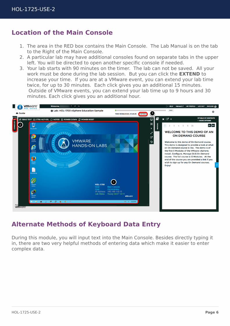
1. The area in the RED box contains the Main Console. The Lab Manual is on the tabto the Right of the Main Console.
2. A particular lab may have additional consoles found on separate tabs in the upperleft. You will be directed to open another specific console if needed.
3. Your lab starts with 90 minutes on the timer. The lab can not be saved. All yourwork must be done during the lab session. But you can click the EXTEND toincrease your time. If you are at a VMware event, you can extend your lab timetwice, for up to 30 minutes. Each click gives you an additional 15 minutes.Outside of VMware events, you can extend your lab time up to 9 hours and 30
minutes. Each click gives you an additional hour.
Alternate Methods of Keyboard Data Entry
During this module, you will input text into the Main Console. Besides directly typing itin, there are two very helpful methods of entering data which make it easier to entercomplex data.
HOL-1725-USE-2
Page 6HOL-1725-USE-2
Click and Drag Lab Manual Content Into Console ActiveWindow
You can also click and drag text and Command Line Interface (CLI) commands directlyfrom the Lab Manual into the active window in the Main Console.
Accessing the Online International Keyboard
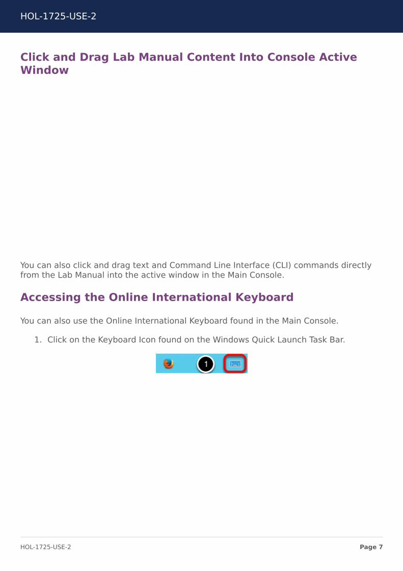
You can also use the Online International Keyboard found in the Main Console.
1. Click on the Keyboard Icon found on the Windows Quick Launch Task Bar.
<div class="player-unavailable"><h1 class="message">An error occurred.</h1><div class="submessage"><ahref="http://www.youtube.com/watch?v=xS07n6GzGuo" target="_blank">Try watching this video on www.youtube.com</a>, or enableJavaScript if it is disabled in your browser.</div></div>
HOL-1725-USE-2
Page 7HOL-1725-USE-2
Click once in active console window
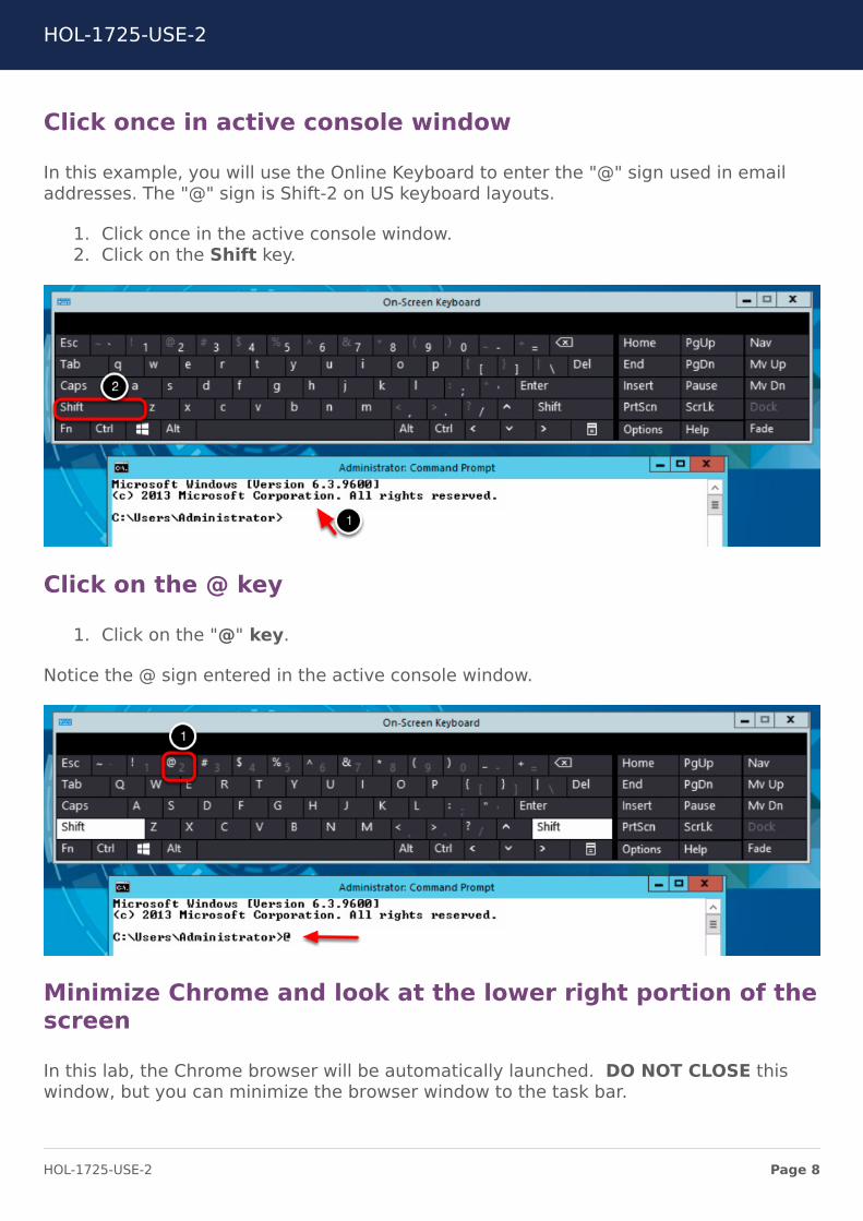
In this example, you will use the Online Keyboard to enter the "@" sign used in emailaddresses. The "@" sign is Shift-2 on US keyboard layouts.
1. Click once in the active console window.2. Click on the Shift key.
Click on the @ key
1. Click on the "@" key.
Notice the @ sign entered in the active console window.
Minimize Chrome and look at the lower right portion of thescreen
In this lab, the Chrome browser will be automatically launched. DO NOT CLOSE thiswindow, but you can minimize the browser window to the task bar.
HOL-1725-USE-2
Page 8HOL-1725-USE-2
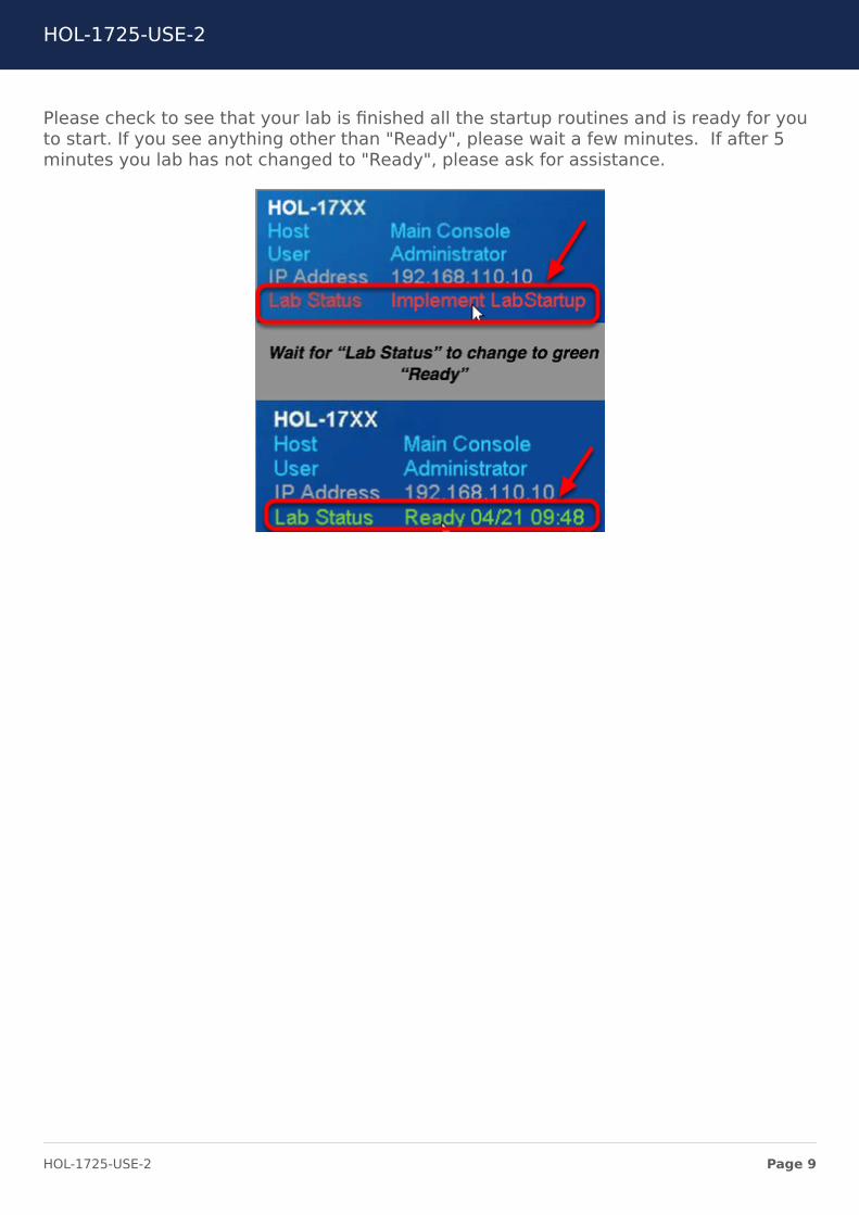
Please check to see that your lab is finished all the startup routines and is ready for youto start. If you see anything other than "Ready", please wait a few minutes. If after 5minutes you lab has not changed to "Ready", please ask for assistance.
HOL-1725-USE-2
Page 9HOL-1725-USE-2
Activation Prompt or Watermark
In this lab, the Chrome browser will be automatically launched. DO NOT CLOSE thiswindow, but you can minimize the browser window to the task bar.
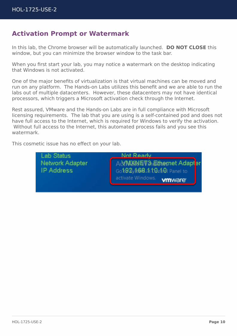
When you first start your lab, you may notice a watermark on the desktop indicatingthat Windows is not activated.
One of the major benefits of virtualization is that virtual machines can be moved andrun on any platform. The Hands-on Labs utilizes this benefit and we are able to run thelabs out of multiple datacenters. However, these datacenters may not have identicalprocessors, which triggers a Microsoft activation check through the Internet.
Rest assured, VMware and the Hands-on Labs are in full compliance with Microsoftlicensing requirements. The lab that you are using is a self-contained pod and does nothave full access to the Internet, which is required for Windows to verify the activation.Without full access to the Internet, this automated process fails and you see this
watermark.
This cosmetic issue has no effect on your lab.
HOL-1725-USE-2
Page 10HOL-1725-USE-2
Module 1 - Review Pre-Configured Multi-Site NSXand Configure Site-Local
Routing (45 Minutes)
HOL-1725-USE-2
Page 11HOL-1725-USE-2
Module GuidanceIn this module, students will review the existing multi-site configuration for variouscomponents such as NSX Managers, vCenter configuration, controller cluster, hostpreparation, logical network preparation as well as configuration of Edge GW's on bothsites. Students will also modify the Locale-ID of the Site RegionB01 to influence theegress traffic for all the application traffic. We will also walk you through configuringrouting between Universal Distributed Logical Routers and Edge GW's on both sitesusing BGP.
HOL-1725-USE-2
Page 12HOL-1725-USE-2
Topology OverviewThis section will familiarize you with the overall lab setup. It describes and explains theenvironment including the pre-configured logical topology, interim topology and finallogical topology after you are done with both Module 1 and 2.
HOL-1725-USE-2
Page 13HOL-1725-USE-2
Virtual Environment Topology
The picture shows the vSphere hosts and how VMs are placed across the differentclusters,the Distributed Virtual Switches (DVS). The VTEP IP addresses associated to thehosts are also displayed.
Clusters RegionA01-MGMT01& RegionA01-COMP01 are both managed by vCenter ServerA (vcsa-01a.corp.local).
RegionB01-COMP01 is managed by vCenter Server B (vcsa-01b.corp.local).
Both vCenters are connected to a common Platform Services Controller(psc-01a.corp.local) that resides on the management network of Region A01.
NSX Transport Zone (TZ) configuration in the lab consists in the following:
• RegionA0_TZ: this TZ has a local scope for vCenter A and is available on bothclusters of Region A01. It is already pre-configured in the lab upon startup.
• Universal_TZ: this TZ has a universal scope and is available on both vCenters. Itis already pre-configured in the lab upon startup.
HOL-1725-USE-2
Page 14HOL-1725-USE-2
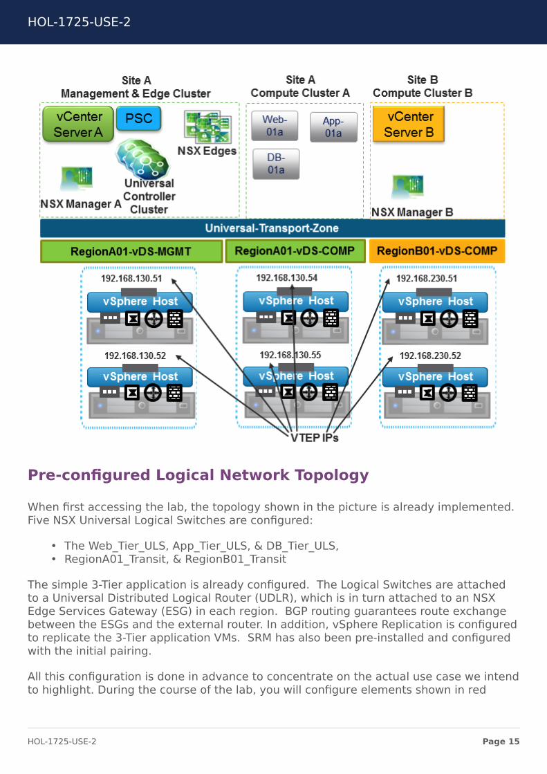
Pre-configured Logical Network Topology
When first accessing the lab, the topology shown in the picture is already implemented.Five NSX Universal Logical Switches are configured:
• The Web_Tier_ULS, App_Tier_ULS, & DB_Tier_ULS,• RegionA01_Transit, & RegionB01_Transit
The simple 3-Tier application is already configured. The Logical Switches are attachedto a Universal Distributed Logical Router (UDLR), which is in turn attached to an NSXEdge Services Gateway (ESG) in each region. BGP routing guarantees route exchangebetween the ESGs and the external router. In addition, vSphere Replication is configuredto replicate the 3-Tier application VMs. SRM has also been pre-installed and configuredwith the initial pairing.
All this configuration is done in advance to concentrate on the actual use case we intendto highlight. During the course of the lab, you will configure elements shown in red
HOL-1725-USE-2
Page 15HOL-1725-USE-2
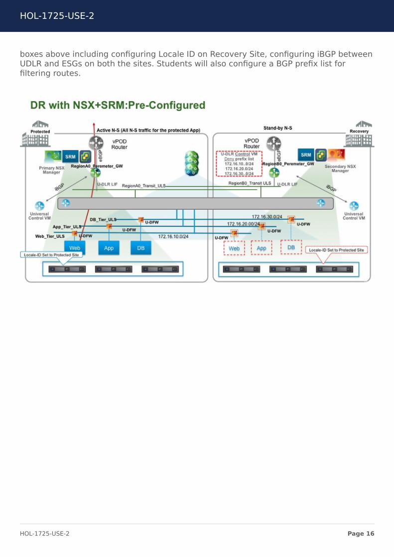
boxes above including configuring Locale ID on Recovery Site, configuring iBGP betweenUDLR and ESGs on both the sites. Students will also configure a BGP prefix list forfiltering routes.
HOL-1725-USE-2
Page 16HOL-1725-USE-2
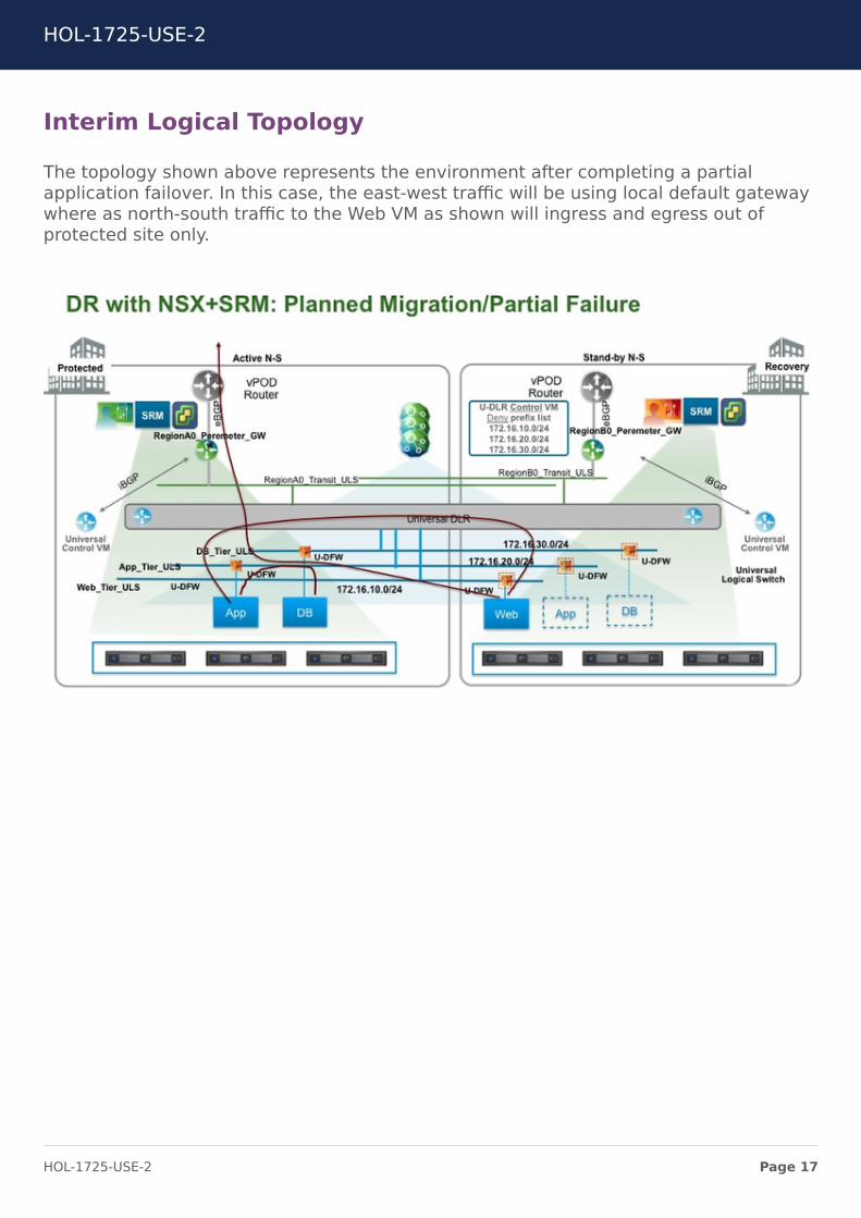
Interim Logical Topology
The topology shown above represents the environment after completing a partialapplication failover. In this case, the east-west traffic will be using local default gatewaywhere as north-south traffic to the Web VM as shown will ingress and egress out ofprotected site only.
HOL-1725-USE-2
Page 17HOL-1725-USE-2
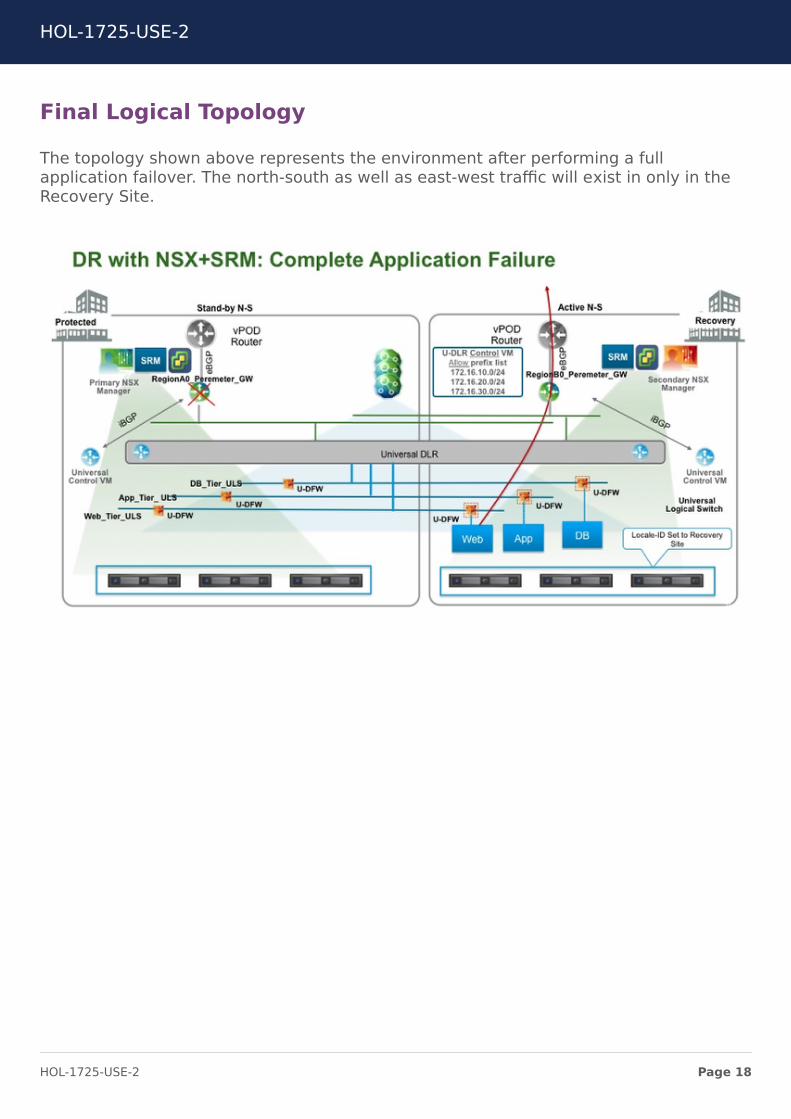
Final Logical Topology
The topology shown above represents the environment after performing a fullapplication failover. The north-south as well as east-west traffic will exist in only in theRecovery Site.
HOL-1725-USE-2
Page 18HOL-1725-USE-2
Review vCenter ConfigurationsIn this lab, the two vCenter servers have been configured in Enhanced Linked Mode.This allows both vCenter Servers to be managed through the same vSphere Web Client
session. While in Enhanced Linked Mode, both NSX envionrments can also beconfigured in the the same vSphere Web Client session.
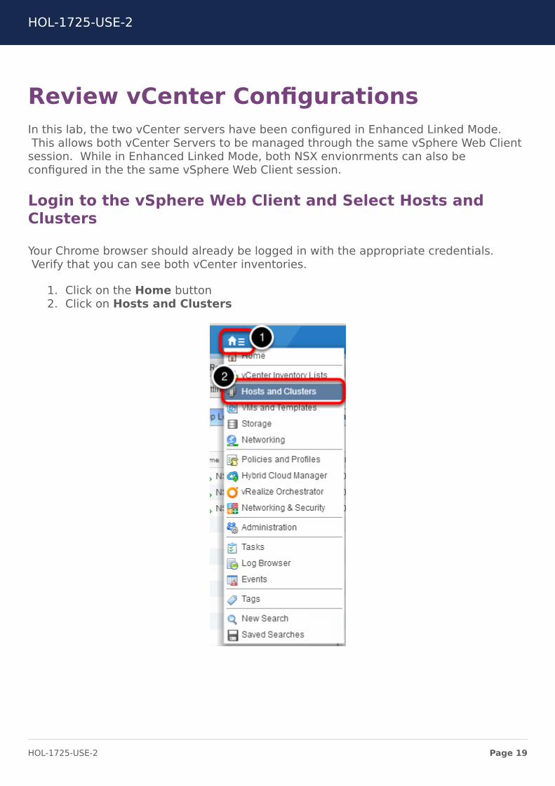
Login to the vSphere Web Client and Select Hosts andClusters
Your Chrome browser should already be logged in with the appropriate credentials.Verify that you can see both vCenter inventories.
1. Click on the Home button2. Click on Hosts and Clusters
HOL-1725-USE-2
Page 19HOL-1725-USE-2
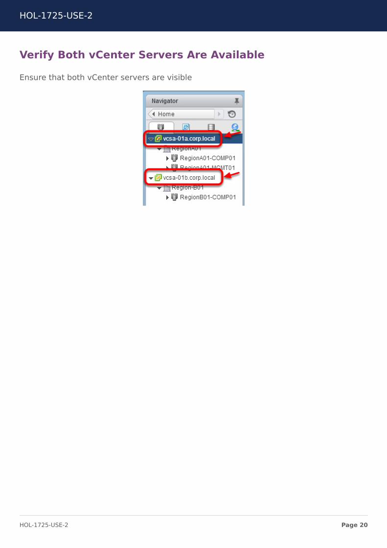
Verify Both vCenter Servers Are Available
Ensure that both vCenter servers are visible
HOL-1725-USE-2
Page 20HOL-1725-USE-2
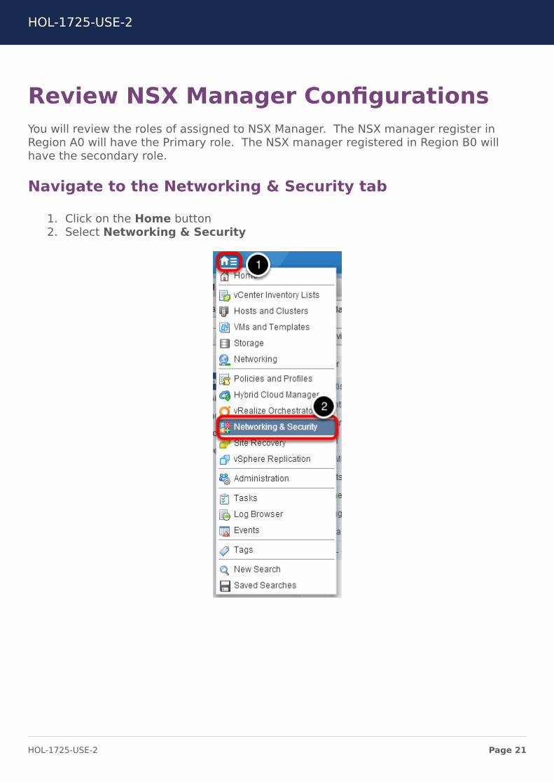
Review NSX Manager ConfigurationsYou will review the roles of assigned to NSX Manager. The NSX manager register inRegion A0 will have the Primary role. The NSX manager registered in Region B0 willhave the secondary role.
Navigate to the Networking & Security tab
1. Click on the Home button2. Select Networking & Security
HOL-1725-USE-2
Page 21HOL-1725-USE-2
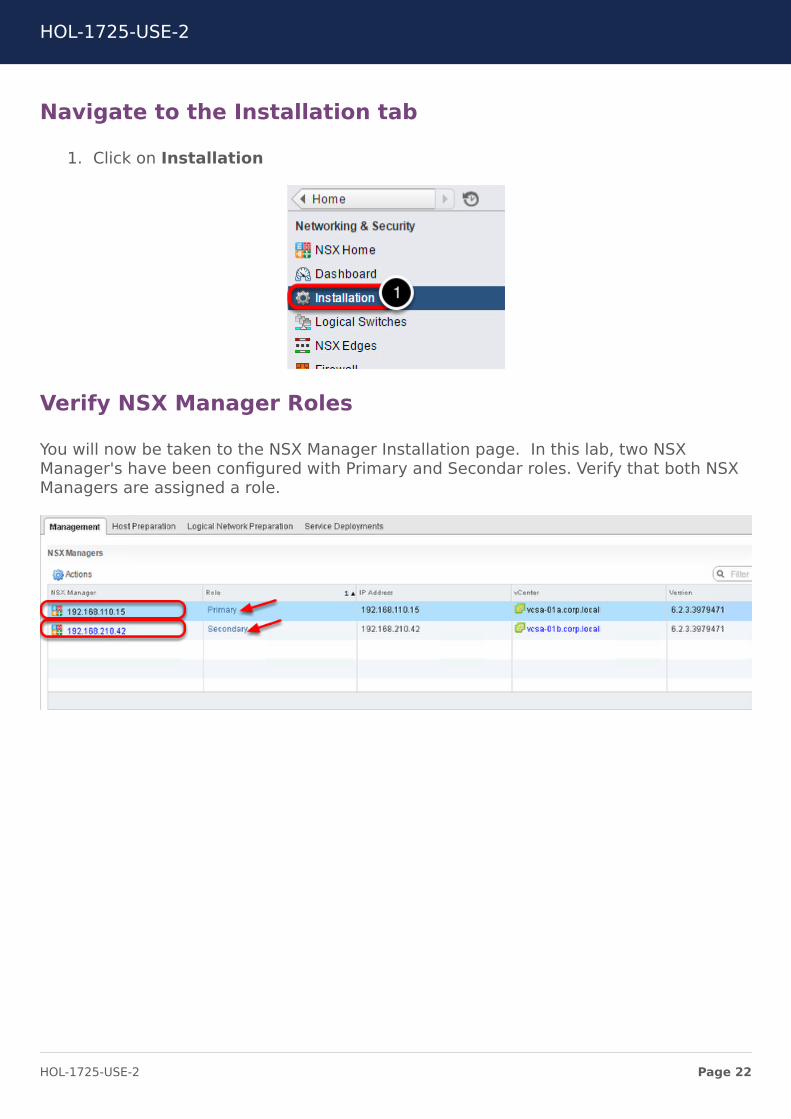
Navigate to the Installation tab
1. Click on Installation
Verify NSX Manager Roles
You will now be taken to the NSX Manager Installation page. In this lab, two NSXManager's have been configured with Primary and Secondar roles. Verify that both NSXManagers are assigned a role.
HOL-1725-USE-2
Page 22HOL-1725-USE-2
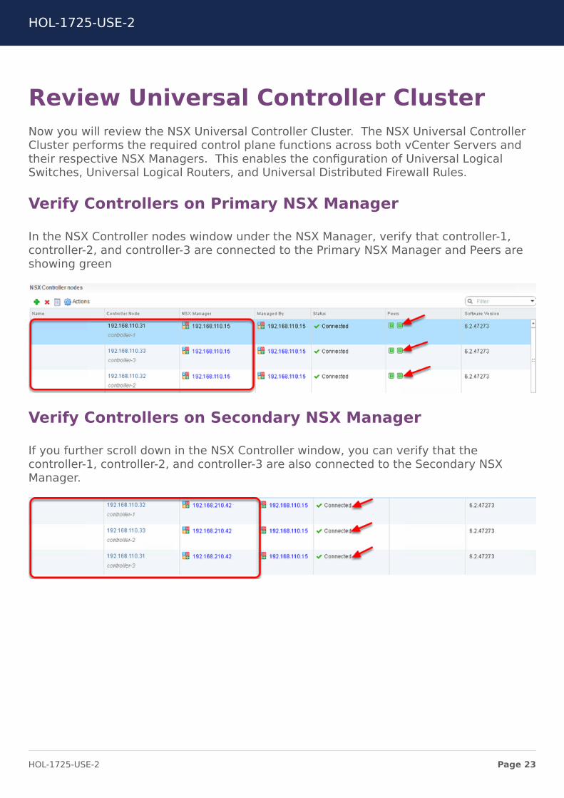
Review Universal Controller ClusterNow you will review the NSX Universal Controller Cluster. The NSX Universal ControllerCluster performs the required control plane functions across both vCenter Servers andtheir respective NSX Managers. This enables the configuration of Universal LogicalSwitches, Universal Logical Routers, and Universal Distributed Firewall Rules.
Verify Controllers on Primary NSX Manager
In the NSX Controller nodes window under the NSX Manager, verify that controller-1,controller-2, and controller-3 are connected to the Primary NSX Manager and Peers areshowing green
Verify Controllers on Secondary NSX Manager
If you further scroll down in the NSX Controller window, you can verify that thecontroller-1, controller-2, and controller-3 are also connected to the Secondary NSXManager.
HOL-1725-USE-2
Page 23HOL-1725-USE-2
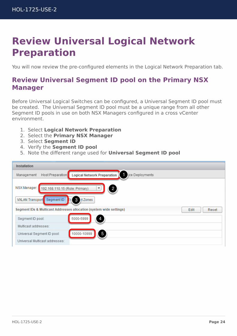
Review Universal Logical NetworkPreparationYou will now review the pre-configured elements in the Logical Network Preparation tab.
Review Universal Segment ID pool on the Primary NSXManager
Before Universal Logical Switches can be configured, a Universal Segment ID pool mustbe created. The Universal Segment ID pool must be a unique range from all otherSegment ID pools in use on both NSX Managers configured in a cross vCenterenvironment.
1. Select Logical Network Preparation2. Select the Primary NSX Manager3. Select Segment ID4. Verify the Segment ID pool5. Note the different range used for Universal Segment ID pool
HOL-1725-USE-2
Page 24HOL-1725-USE-2
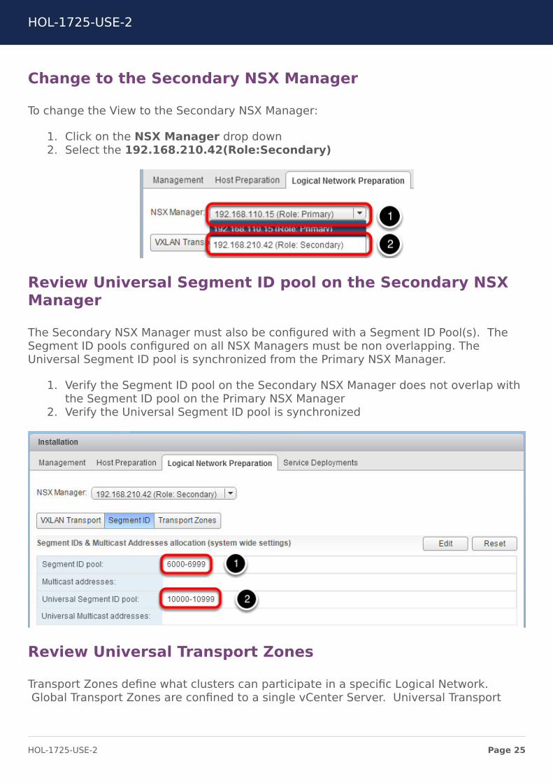
Change to the Secondary NSX Manager
To change the View to the Secondary NSX Manager:
1. Click on the NSX Manager drop down2. Select the 192.168.210.42(Role:Secondary)
Review Universal Segment ID pool on the Secondary NSXManager
The Secondary NSX Manager must also be configured with a Segment ID Pool(s). TheSegment ID pools configured on all NSX Managers must be non overlapping. TheUniversal Segment ID pool is synchronized from the Primary NSX Manager.
1. Verify the Segment ID pool on the Secondary NSX Manager does not overlap withthe Segment ID pool on the Primary NSX Manager
2. Verify the Universal Segment ID pool is synchronized
Review Universal Transport Zones
Transport Zones define what clusters can participate in a specific Logical Network.Global Transport Zones are confined to a single vCenter Server. Universal Transport
HOL-1725-USE-2
Page 25HOL-1725-USE-2
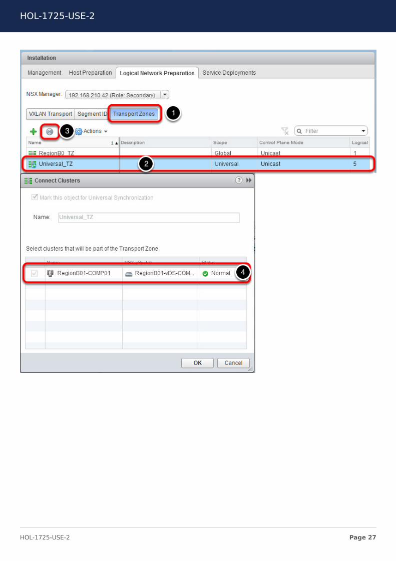
Zones may span vCenter Servers. Verify the clusters connected to the Universal TransitZone.
1. Select Transport Zones2. Select Universal_TZ3. Click the Connect Clusters icon4. Verify the cluster RegionB01-COMP01 is connected and in Normal status
Switch to the Primary NSX Manager by changing the in the drop-down from the previousstep and review the configuration of the Universal_TZ. Using the same view and stepsoutlined above. Verify clusters RegionA01-COMP01 and RegionA01-MGMT01 areconnected and in Normal status.
HOL-1725-USE-2
Page 26HOL-1725-USE-2
HOL-1725-USE-2
Page 27HOL-1725-USE-2
Review the Logical Switches in theEnvironment & Create a new UniversalLogical SwitchesNext, you will review the pre-configured Universal Logical Switches and create a newULS.
Review Universal Logical Switches on Primary NSXManager
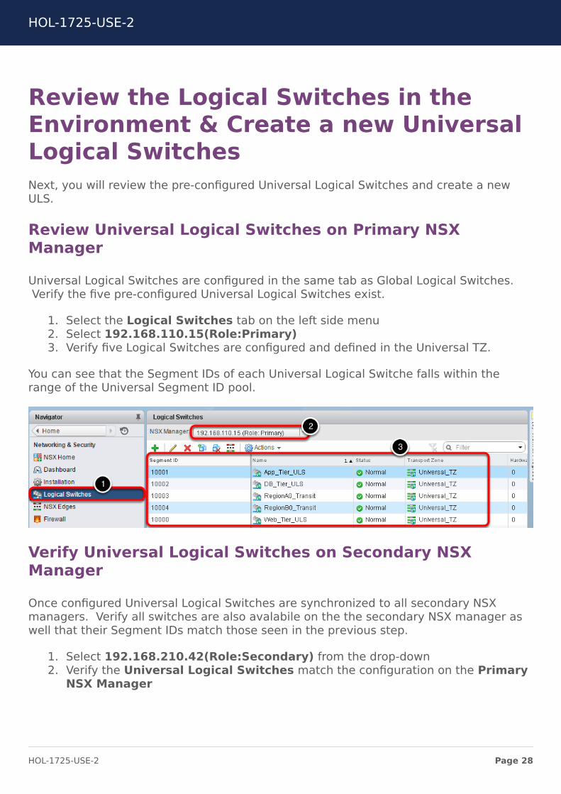
Universal Logical Switches are configured in the same tab as Global Logical Switches.Verify the five pre-configured Universal Logical Switches exist.
1. Select the Logical Switches tab on the left side menu2. Select 192.168.110.15(Role:Primary)3. Verify five Logical Switches are configured and defined in the Universal TZ.
You can see that the Segment IDs of each Universal Logical Switche falls within therange of the Universal Segment ID pool.
Verify Universal Logical Switches on Secondary NSXManager
Once configured Universal Logical Switches are synchronized to all secondary NSXmanagers. Verify all switches are also avalabile on the the secondary NSX manager aswell that their Segment IDs match those seen in the previous step.
1. Select 192.168.210.42(Role:Secondary) from the drop-down2. Verify the Universal Logical Switches match the configuration on the Primary
NSX Manager
HOL-1725-USE-2
Page 28HOL-1725-USE-2
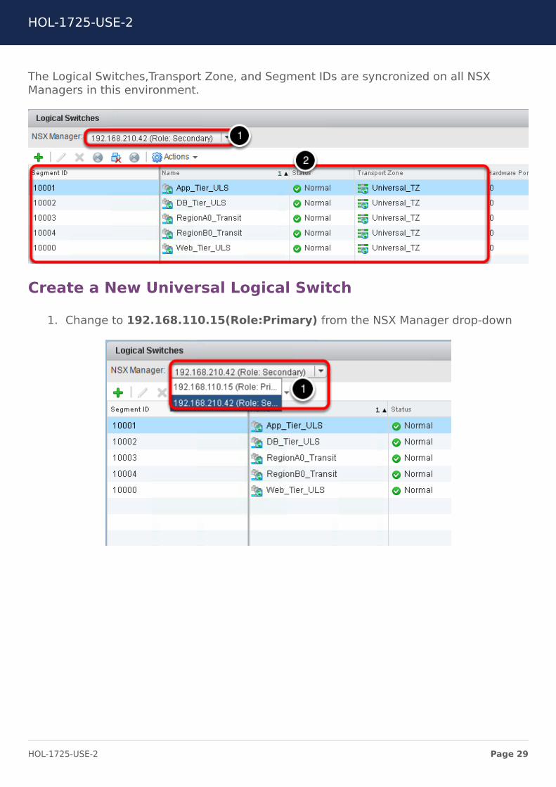
The Logical Switches,Transport Zone, and Segment IDs are syncronized on all NSXManagers in this environment.
Create a New Universal Logical Switch
1. Change to 192.168.110.15(Role:Primary) from the NSX Manager drop-down
HOL-1725-USE-2
Page 29HOL-1725-USE-2

Create Universal Logical Switch
Universal Logical Switches are only configurable on the Primary NSX Manager, then theyare synchronized across the remaining NSX Managers. Create a Universal LogicalSwitch on the Primary NSX Manager
1. Click on the green plus sign to add Logical Switch
HOL-1725-USE-2
Page 30HOL-1725-USE-2
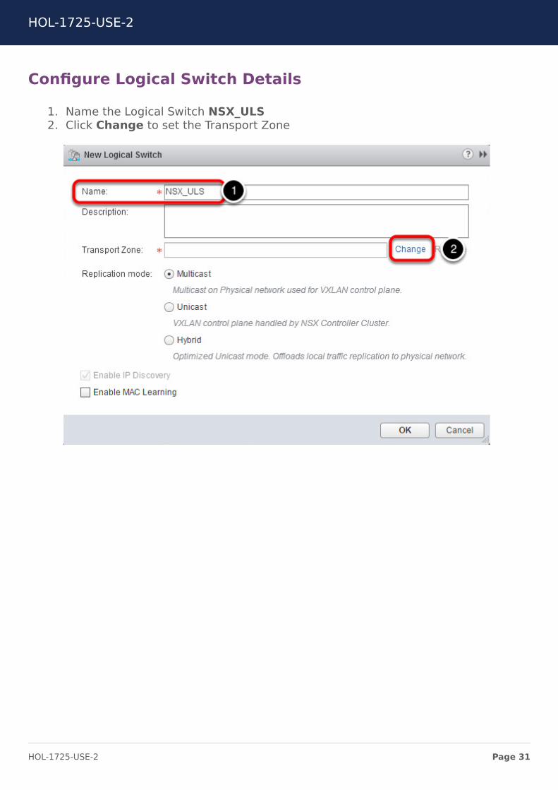
Configure Logical Switch Details
1. Name the Logical Switch NSX_ULS2. Click Change to set the Transport Zone
HOL-1725-USE-2
Page 31HOL-1725-USE-2
Select the Universal Transport Zone
1. Select Radio Button for Universal_TZ2. Click OK3. Click OK
HOL-1725-USE-2
Page 32HOL-1725-USE-2
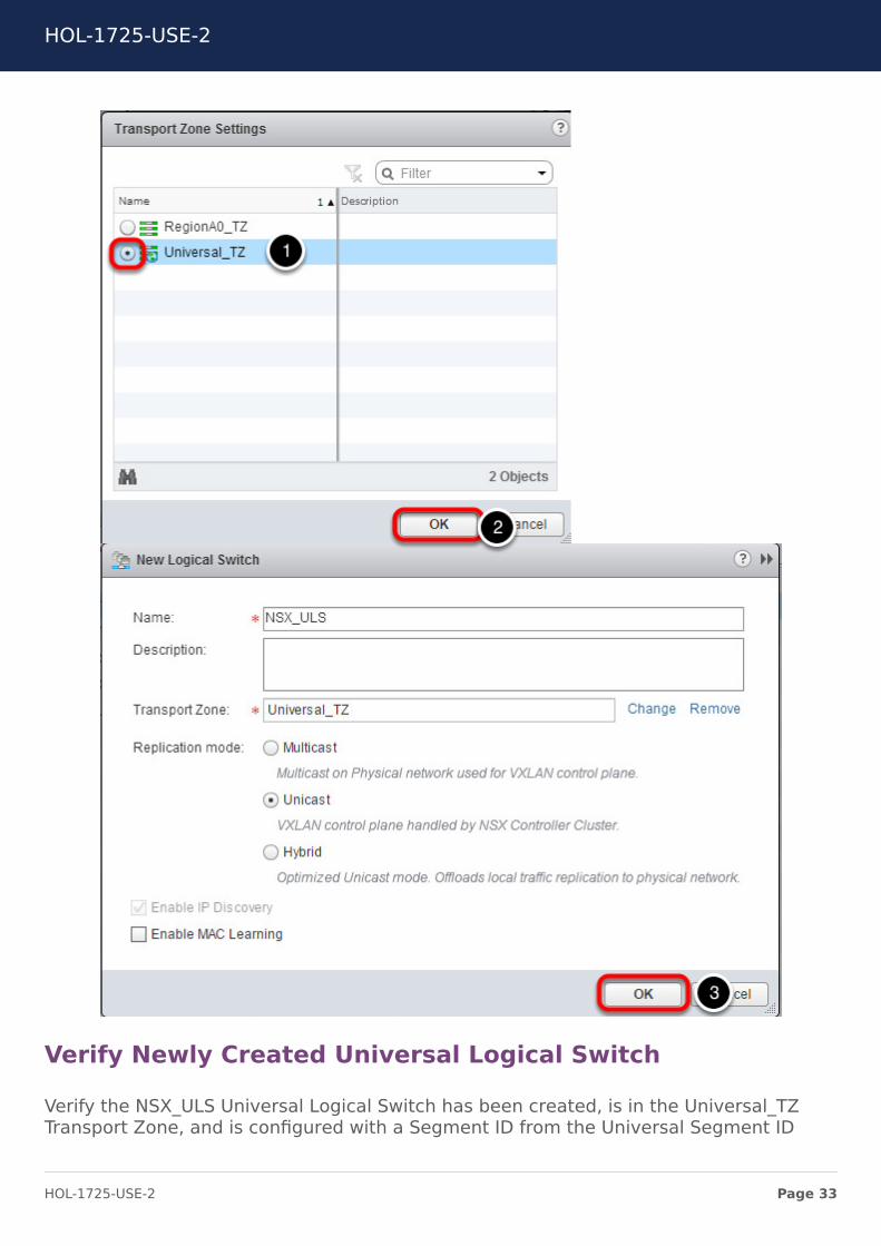
Verify Newly Created Universal Logical Switch
Verify the NSX_ULS Universal Logical Switch has been created, is in the Universal_TZTransport Zone, and is configured with a Segment ID from the Universal Segment ID
HOL-1725-USE-2
Page 33HOL-1725-USE-2
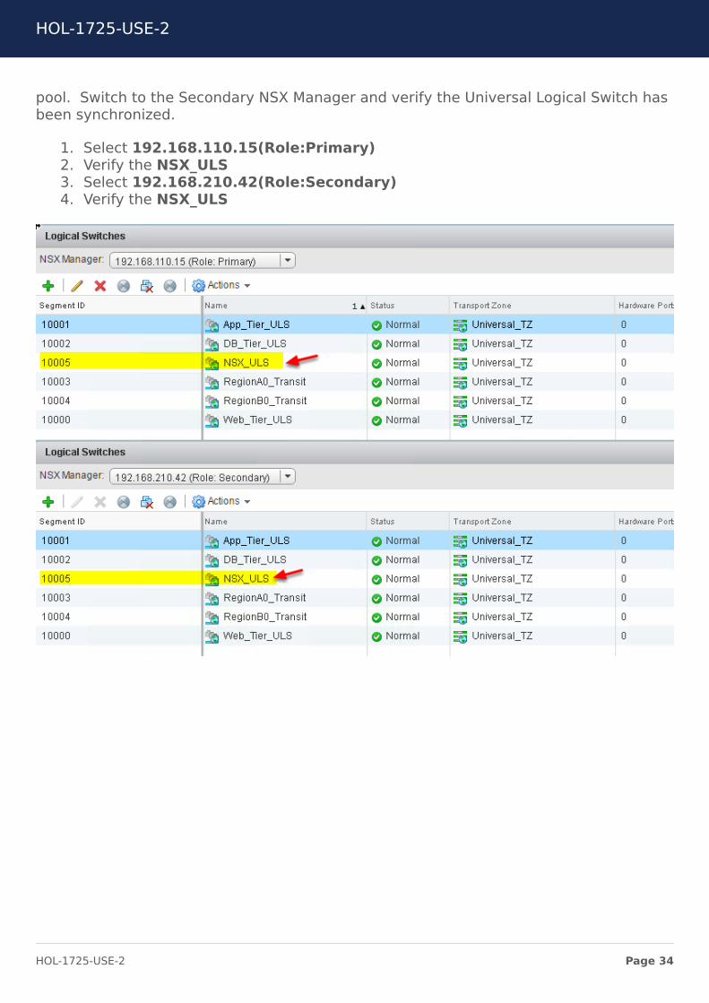
pool. Switch to the Secondary NSX Manager and verify the Universal Logical Switch hasbeen synchronized.
1. Select 192.168.110.15(Role:Primary)2. Verify the NSX_ULS3. Select 192.168.210.42(Role:Secondary)4. Verify the NSX_ULS
HOL-1725-USE-2
Page 34HOL-1725-USE-2
Review NSX Edge ConfigurationsIn this lab, NSX Edge devices provide connectivity for north-south communication aswell as east-west communication. There are two pre-configured NSX Edge devices fornorth-south communication. These perimeter gateways are configured with dynamicrouting utilizing BGP. The perimeter gateways utilize equal cost multipathing (ECMP) toallow traffic in and out of both sites. A third NSX Edge has been pre-configured as aUniversal Distributed Logical Router (UDLR) providing east-west routing among theapplication logical switches as well as connectivity to a transit ULS in each site for north-south communication to the perimeter gateway ESGs. This UDLR has been configuredfor ECMP and local egress.
HOL-1725-USE-2
Page 35HOL-1725-USE-2
Local Egress
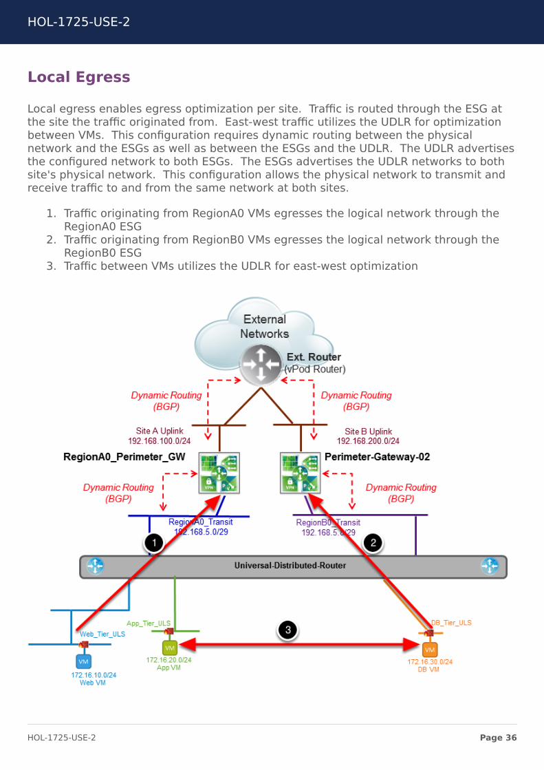
Local egress enables egress optimization per site. Traffic is routed through the ESG atthe site the traffic originated from. East-west traffic utilizes the UDLR for optimizationbetween VMs. This configuration requires dynamic routing between the physicalnetwork and the ESGs as well as between the ESGs and the UDLR. The UDLR advertisesthe configured network to both ESGs. The ESGs advertises the UDLR networks to bothsite's physical network. This configuration allows the physical network to transmit andreceive traffic to and from the same network at both sites.
1. Traffic originating from RegionA0 VMs egresses the logical network through theRegionA0 ESG
2. Traffic originating from RegionB0 VMs egresses the logical network through theRegionB0 ESG
3. Traffic between VMs utilizes the UDLR for east-west optimization
HOL-1725-USE-2
Page 36HOL-1725-USE-2
Review Perimeter Gateway Configurations
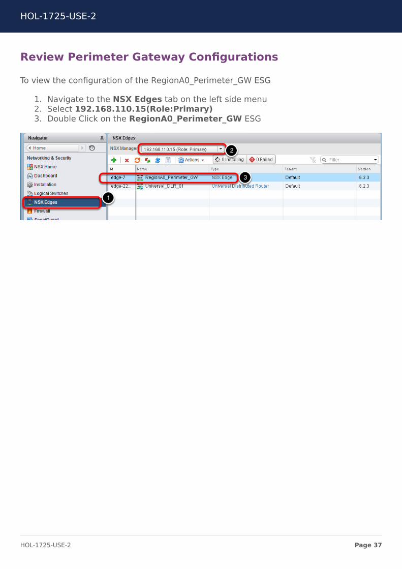
To view the configuration of the RegionA0_Perimeter_GW ESG
1. Navigate to the NSX Edges tab on the left side menu2. Select 192.168.110.15(Role:Primary)3. Double Click on the RegionA0_Perimeter_GW ESG
HOL-1725-USE-2
Page 37HOL-1725-USE-2

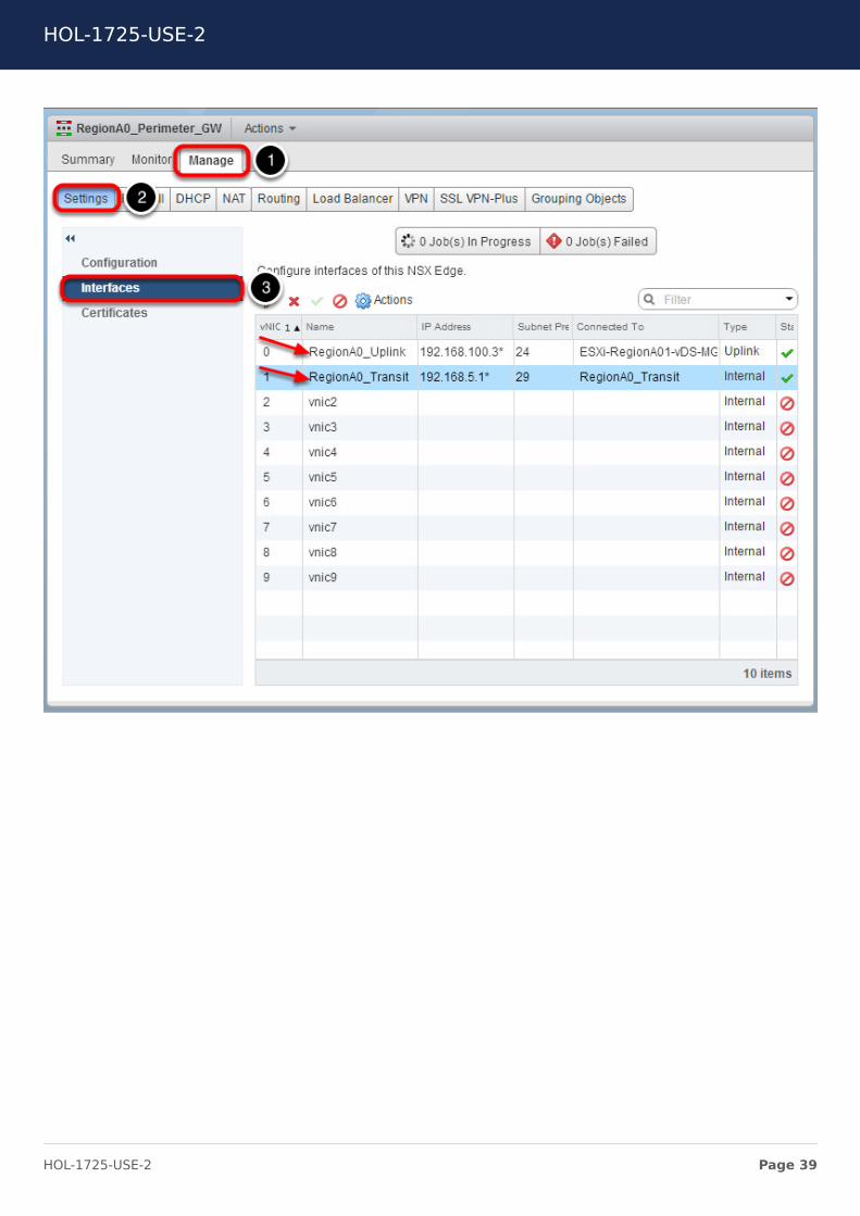
Review the Interface Configuration
To view the interface configuration
1. Select the Manage tab2. Select the Settings tab3. Select the Interfaces section
Review the Interfaces configured
vNIC0 is configured with an address in the subnet of the RegionA0 uplink network. It isconnected to the VLAN backed portgroup ESXi-RegionA01-vDS-COMP. The type ofinterface is an uplink typically providing updates to the datacenter's physical routinginfrastructure.
vNIC1 is configured with an address in the subnet of the RegionA0_Transit network. It isconnected to the Universal Logical Switch RegionA0_Transit. The type of interface isinternal (and in this case) connected downstream to a logical switch shared by theUDLR.
HOL-1725-USE-2
Page 38HOL-1725-USE-2
HOL-1725-USE-2
Page 39HOL-1725-USE-2
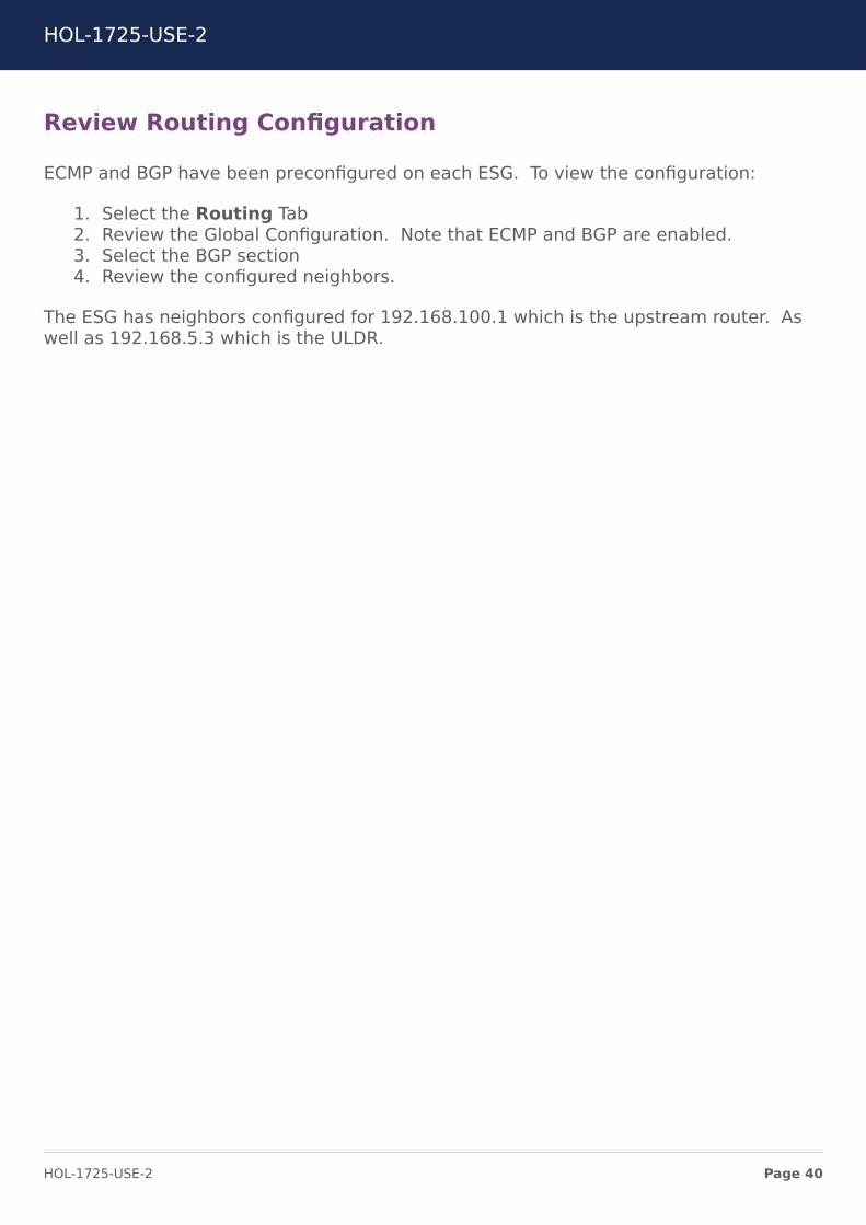
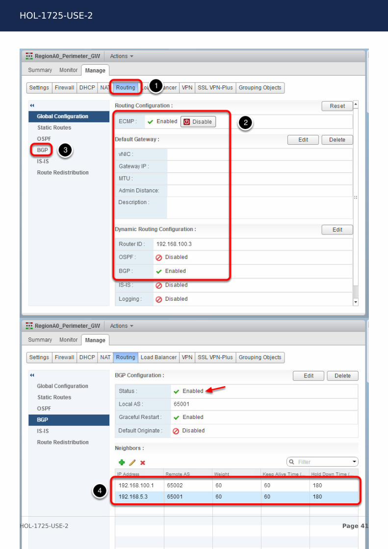
Review Routing Configuration
ECMP and BGP have been preconfigured on each ESG. To view the configuration:
1. Select the Routing Tab2. Review the Global Configuration. Note that ECMP and BGP are enabled.3. Select the BGP section4. Review the configured neighbors.
The ESG has neighbors configured for 192.168.100.1 which is the upstream router. Aswell as 192.168.5.3 which is the ULDR.
HOL-1725-USE-2
Page 40HOL-1725-USE-2
HOL-1725-USE-2
Page 41HOL-1725-USE-2
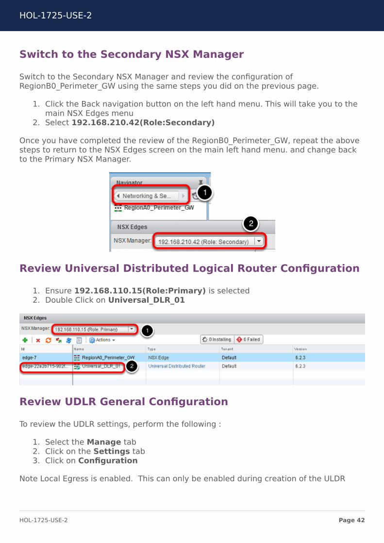
Switch to the Secondary NSX Manager
Switch to the Secondary NSX Manager and review the configuration ofRegionB0_Perimeter_GW using the same steps you did on the previous page.
1. Click the Back navigation button on the left hand menu. This will take you to themain NSX Edges menu
2. Select 192.168.210.42(Role:Secondary)
Once you have completed the review of the RegionB0_Perimeter_GW, repeat the abovesteps to return to the NSX Edges screen on the main left hand menu. and change backto the Primary NSX Manager.
Review Universal Distributed Logical Router Configuration
1. Ensure 192.168.110.15(Role:Primary) is selected2. Double Click on Universal_DLR_01
Review UDLR General Configuration
To review the UDLR settings, perform the following :
1. Select the Manage tab2. Click on the Settings tab3. Click on Configuration
Note Local Egress is enabled. This can only be enabled during creation of the ULDR
HOL-1725-USE-2
Page 42HOL-1725-USE-2
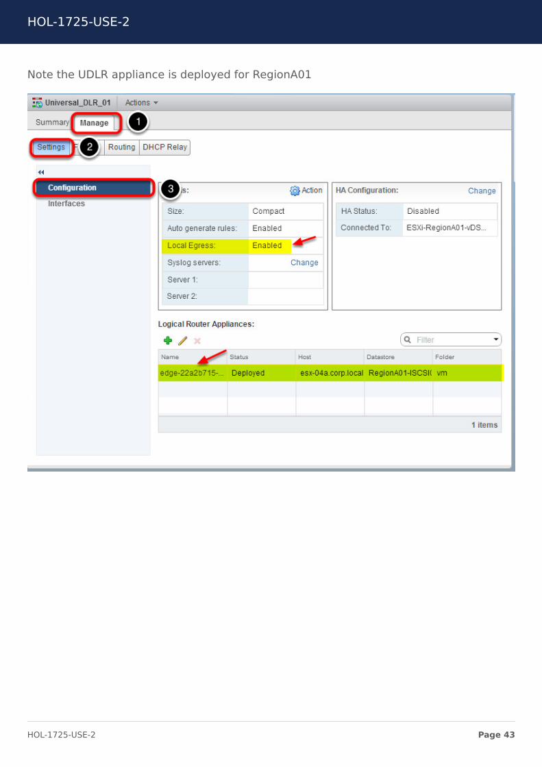
Note the UDLR appliance is deployed for RegionA01
HOL-1725-USE-2
Page 43HOL-1725-USE-2
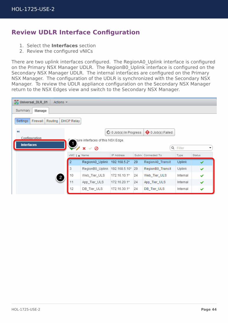
Review UDLR Interface Configuration
1. Select the Interfaces section2. Review the configured vNICs
There are two uplink interfaces configured. The RegionA0_Uplink interface is configuredon the Primary NSX Manager UDLR. The RegionB0_Uplink interface is configured on theSecondary NSX Manager UDLR. The internal interfaces are configured on the PrimaryNSX Manager. The configuration of the UDLR is synchronized with the Secondary NSXManager. To review the UDLR appliance configuration on the Secondary NSX Managerreturn to the NSX Edges view and switch to the Secondary NSX Manager.
HOL-1725-USE-2
Page 44HOL-1725-USE-2
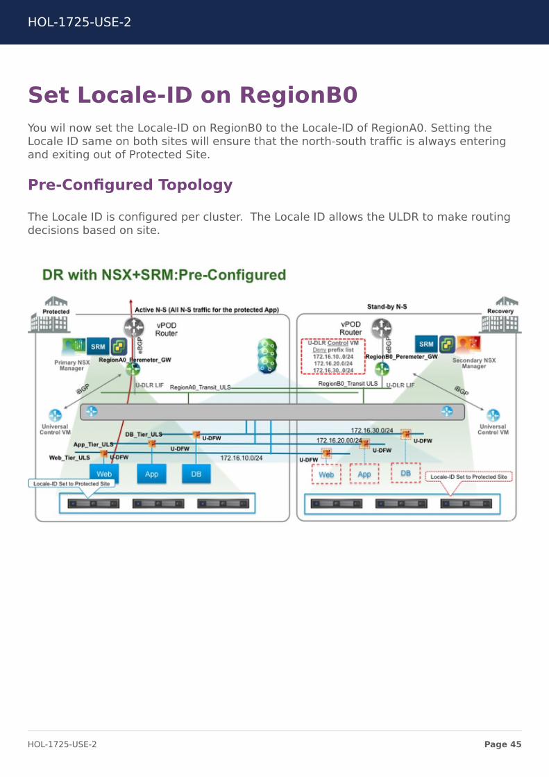
Set Locale-ID on RegionB0You wil now set the Locale-ID on RegionB0 to the Locale-ID of RegionA0. Setting theLocale ID same on both sites will ensure that the north-south traffic is always enteringand exiting out of Protected Site.
Pre-Configured Topology
The Locale ID is configured per cluster. The Locale ID allows the ULDR to make routingdecisions based on site.
HOL-1725-USE-2
Page 45HOL-1725-USE-2
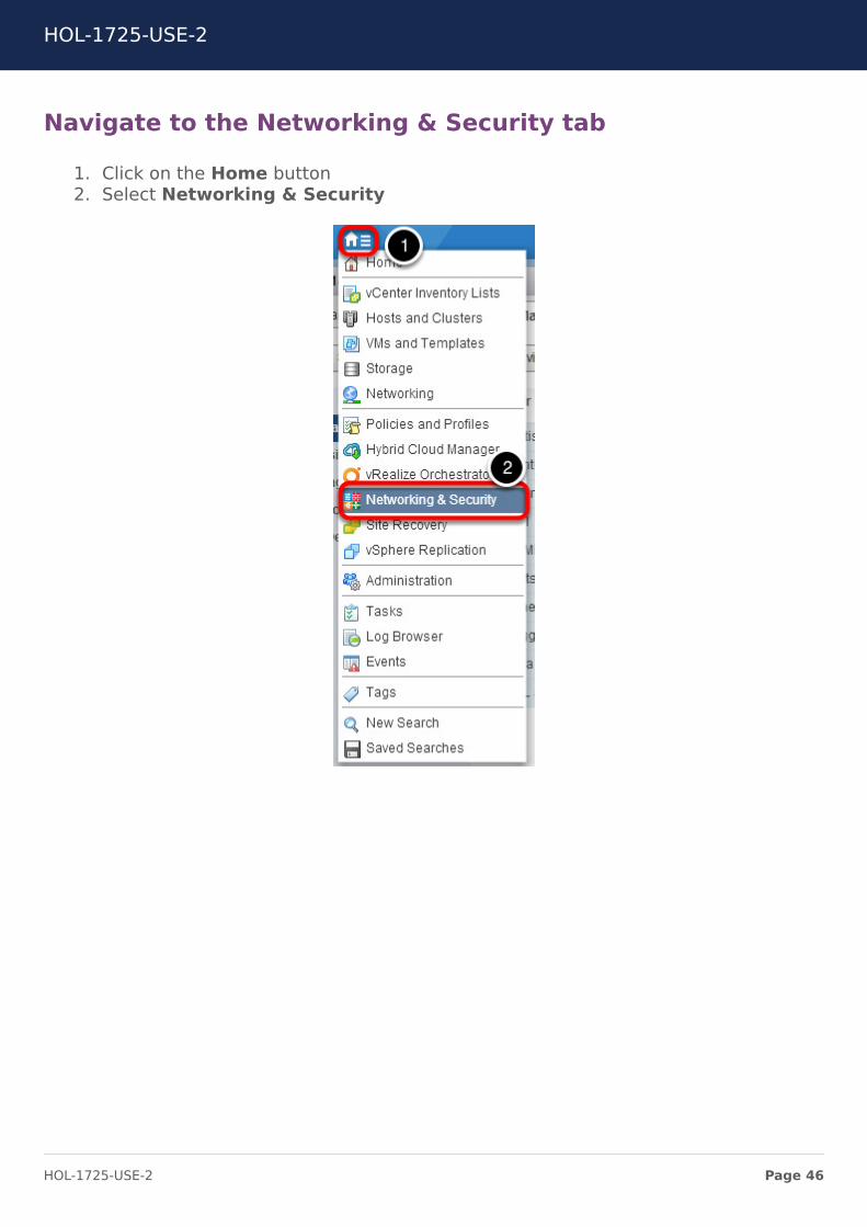
Navigate to the Networking & Security tab
1. Click on the Home button2. Select Networking & Security
HOL-1725-USE-2
Page 46HOL-1725-USE-2
Navigate to the Installation tab
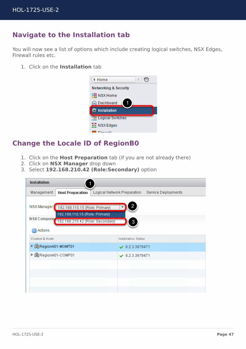
You will now see a list of options which include creating logical switches, NSX Edges,Firewall rules etc.
1. Click on the Installation tab
Change the Locale ID of RegionB0
1. Click on the Host Preparation tab (if you are not already there)2. Click on NSX Manager drop down3. Select 192.168.210.42 (Role:Secondary) option
HOL-1725-USE-2
Page 47HOL-1725-USE-2
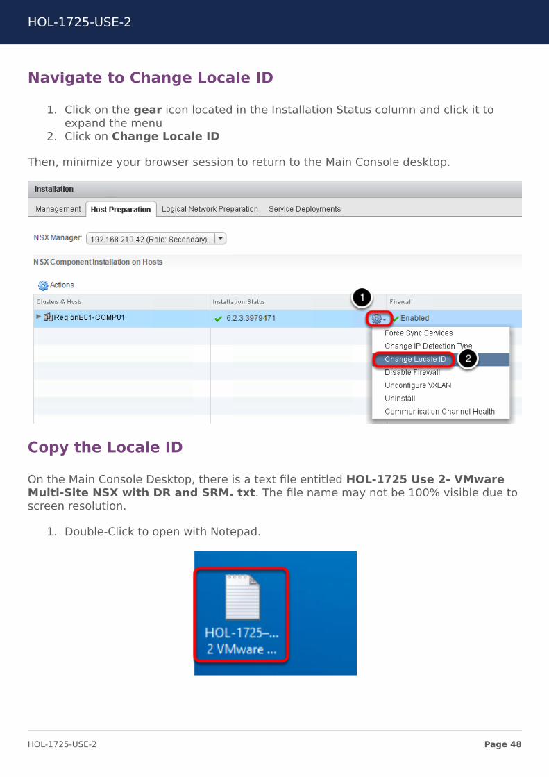
Navigate to Change Locale ID
1. Click on the gear icon located in the Installation Status column and click it toexpand the menu
2. Click on Change Locale ID
Then, minimize your browser session to return to the Main Console desktop.
Copy the Locale ID
On the Main Console Desktop, there is a text file entitled HOL-1725 Use 2- VMwareMulti-Site NSX with DR and SRM. txt. The file name may not be 100% visible due toscreen resolution.
1. Double-Click to open with Notepad.
HOL-1725-USE-2
Page 48HOL-1725-USE-2
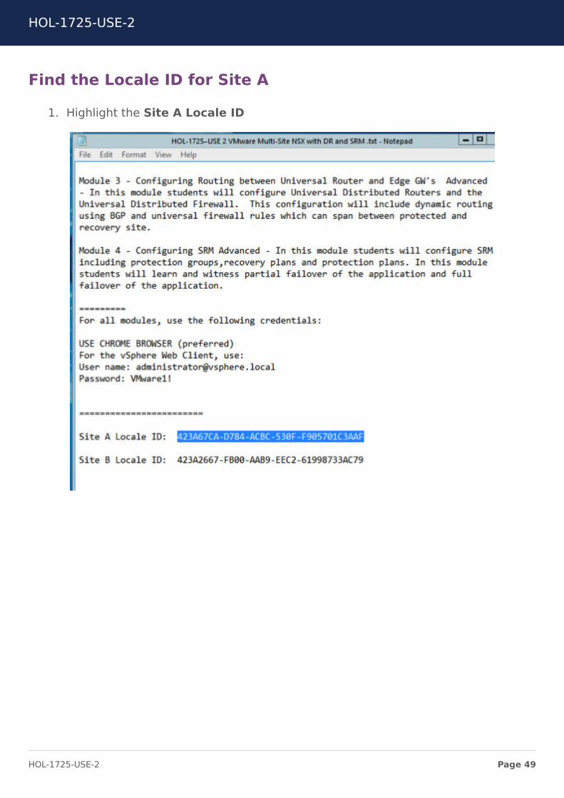
Find the Locale ID for Site A
1. Highlight the Site A Locale ID
HOL-1725-USE-2
Page 49HOL-1725-USE-2
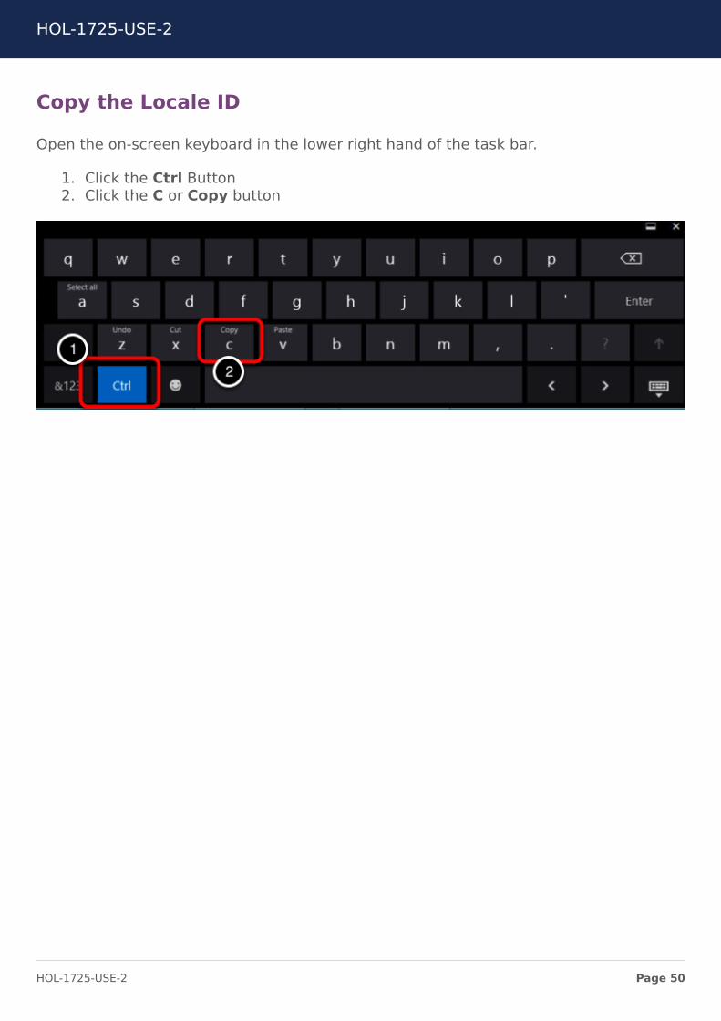
Copy the Locale ID
Open the on-screen keyboard in the lower right hand of the task bar.
1. Click the Ctrl Button2. Click the C or Copy button
HOL-1725-USE-2
Page 50HOL-1725-USE-2
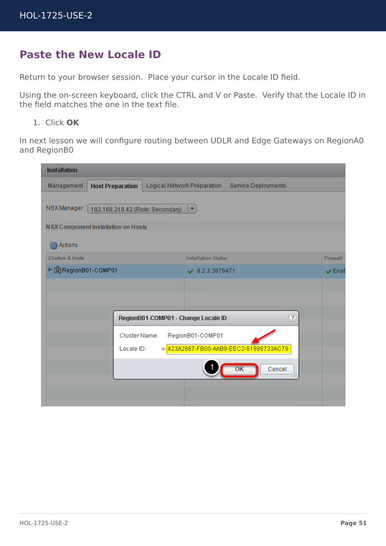
Paste the New Locale ID
Return to your browser session. Place your cursor in the Locale ID field.
Using the on-screen keyboard, click the CTRL and V or Paste. Verify that the Locale ID inthe field matches the one in the text file.
1. Click OK
In next lesson we will configure routing between UDLR and Edge Gateways on RegionA0and RegionB0
HOL-1725-USE-2
Page 51HOL-1725-USE-2
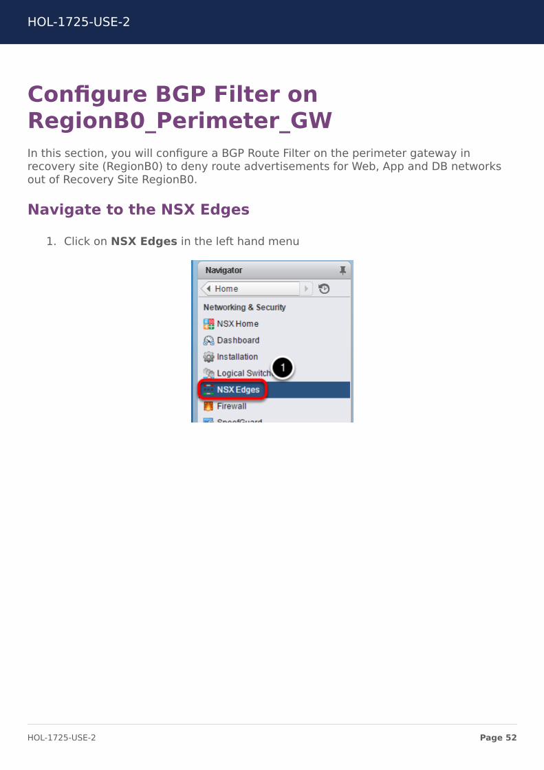
Configure BGP Filter onRegionB0_Perimeter_GWIn this section, you will configure a BGP Route Filter on the perimeter gateway inrecovery site (RegionB0) to deny route advertisements for Web, App and DB networksout of Recovery Site RegionB0.
Navigate to the NSX Edges
1. Click on NSX Edges in the left hand menu
HOL-1725-USE-2
Page 52HOL-1725-USE-2
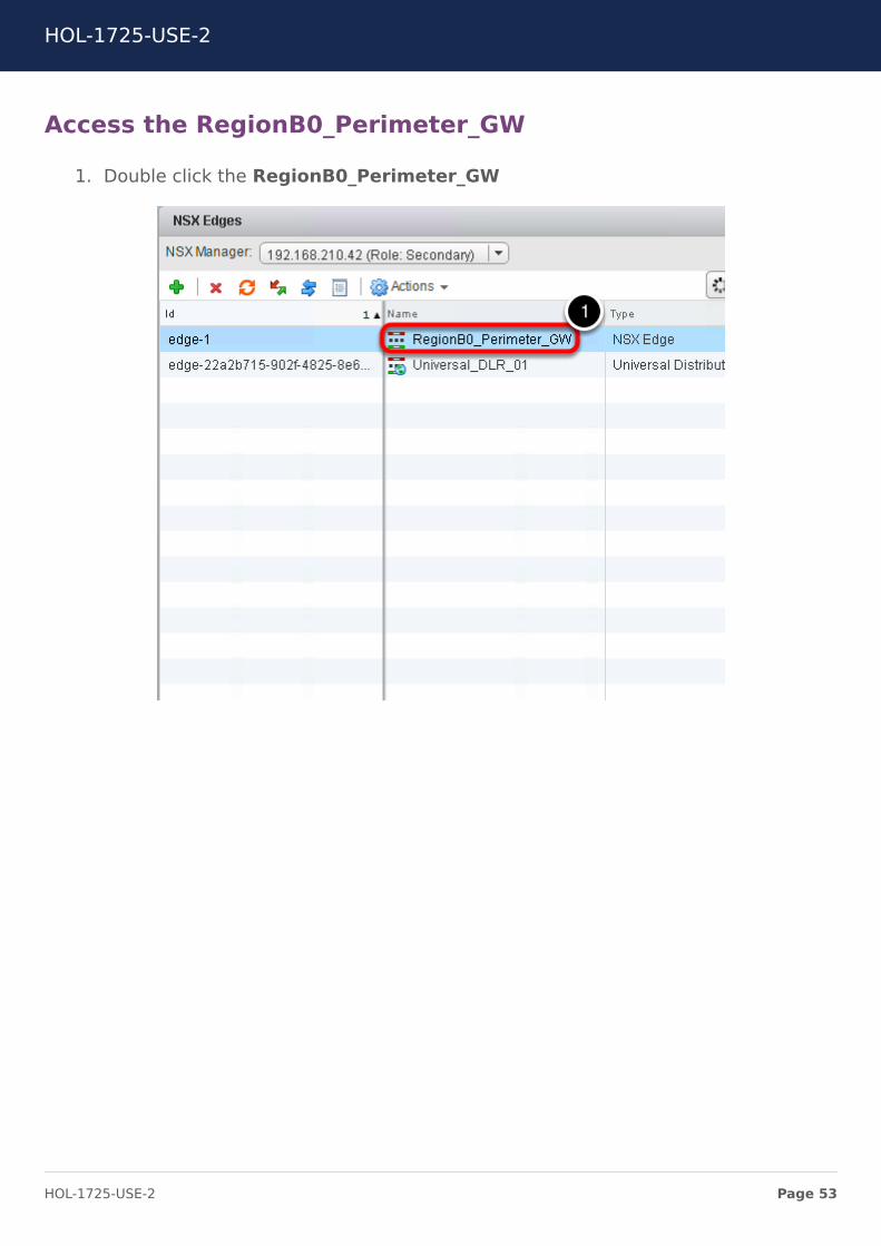
Access the RegionB0_Perimeter_GW
1. Double click the RegionB0_Perimeter_GW
HOL-1725-USE-2
Page 53HOL-1725-USE-2
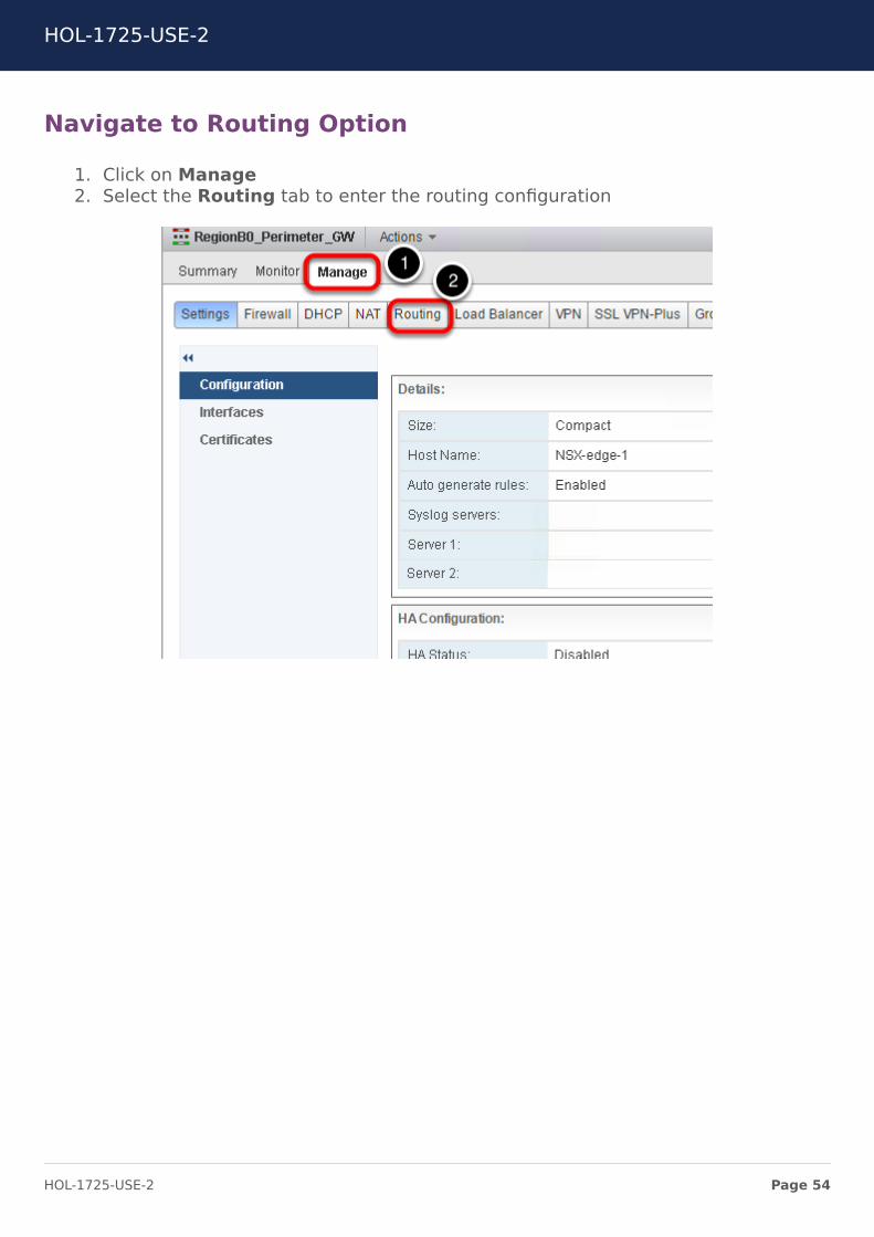
Navigate to Routing Option
1. Click on Manage2. Select the Routing tab to enter the routing configuration
HOL-1725-USE-2
Page 54HOL-1725-USE-2
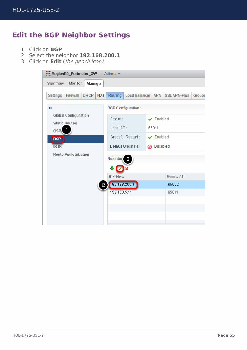
Edit the BGP Neighbor Settings
1. Click on BGP2. Select the neighbor 192.168.200.13. Click on Edit (the pencil icon)
HOL-1725-USE-2
Page 55HOL-1725-USE-2
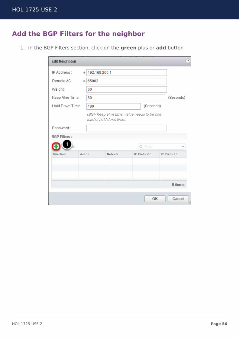
Add the BGP Filters for the neighbor
1. In the BGP Filters section, click on the green plus or add button
HOL-1725-USE-2
Page 56HOL-1725-USE-2
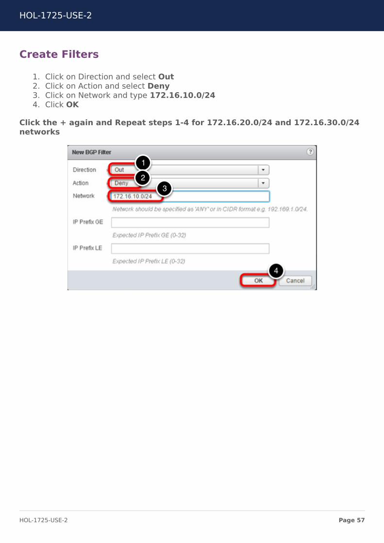
Create Filters
1. Click on Direction and select Out2. Click on Action and select Deny3. Click on Network and type 172.16.10.0/244. Click OK
Click the + again and Repeat steps 1-4 for 172.16.20.0/24 and 172.16.30.0/24networks
HOL-1725-USE-2
Page 57HOL-1725-USE-2
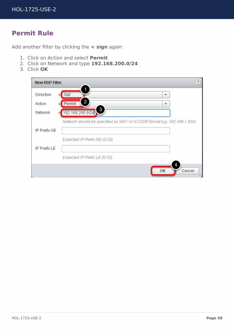
Permit Rule
Add another filter by clicking the + sign again
1. Click on Action and select Permit2. Click on Network and type 192.168.200.0/243. Click OK
HOL-1725-USE-2
Page 58HOL-1725-USE-2
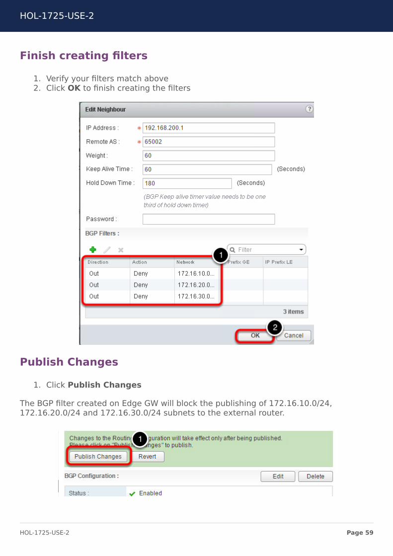
Finish creating filters
1. Verify your filters match above2. Click OK to finish creating the filters
Publish Changes
1. Click Publish Changes
The BGP filter created on Edge GW will block the publishing of 172.16.10.0/24,172.16.20.0/24 and 172.16.30.0/24 subnets to the external router.
HOL-1725-USE-2
Page 59HOL-1725-USE-2

Enable BGP on Universal LogicalRouter RegionA0You will now configure BGP on the Universal Logical Distributed Router.
Navigate to NSX Edges
1. Click on NSX Edges on the left side menu
Select the Primary NSX Manager
1. Click on the NSX Manager drop down menu2. Select 192.168.110.15 (Role:Primary)
HOL-1725-USE-2
Page 60HOL-1725-USE-2

Navigate to the UDLR
1. Double click on Universal_DLR_01
Edit the Routing of the UDLR
1. Click on Manage2. Click on Routing
Edit Dynamic Routing Configuration
The Router ID is a required setting for dynamic routing. The Router ID is a unique valuethat identifies the router in the routing table. This is normally an IP address configuredon the router.
1. Click the Edit Button in the upper right hand corner2. Select RegionA0_Uplink as the Router ID
HOL-1725-USE-2
Page 61HOL-1725-USE-2
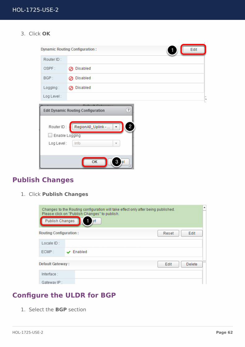
3. Click OK
Publish Changes
1. Click Publish Changes
Configure the ULDR for BGP
1. Select the BGP section
HOL-1725-USE-2
Page 62HOL-1725-USE-2

2. Under BGP Configuration click Edit
Enable BGP
BGP must be enabled and a Local Autonomous System (AS) must be configured. The ASis configured globally on an ESG, DLR, & ULDR.
1. Check the Enable BGP check box2. Enter 65001 as the Local AS3. Click OK
HOL-1725-USE-2
Page 63HOL-1725-USE-2
Add a Neighbor
Add the RegionA0_Perimeter_GW as a Neighboor. The IP address is the IP of the internalinterface or the RegionA0_Perimeter_GW. The forwarding address is the IP address ofthe Universal_DLR RegionA0 uplink interface. The protocol address is an unused IPaddress in the same network as the forwarding address. The RegionA0_Perimeter_GWESG is configured with this address as a BGP neighboor. The forwarding address is usedas the data plane while the protocol address is used in the control plane.
1. In the Neighbour Section, Click the Green Plus2. in the IP Address field, enter 192.168.5.13. In the Forwarding Address field, enter 192.168.5.24. In the Protocol Address field, enter 192.168.5.35. In the Remote AS Field, Enter 65001
Leave all other fields as their default.
6. Click OK
HOL-1725-USE-2
Page 64HOL-1725-USE-2
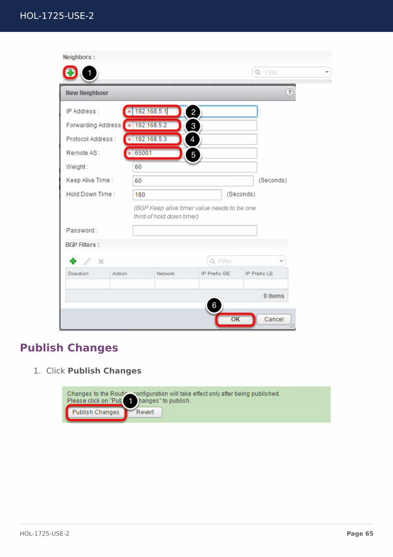
Publish Changes
1. Click Publish Changes
HOL-1725-USE-2
Page 65HOL-1725-USE-2
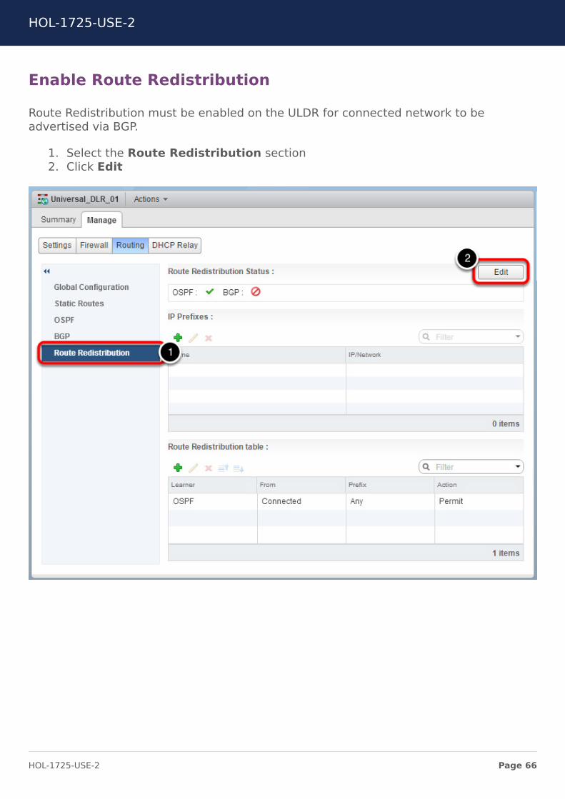
Enable Route Redistribution
Route Redistribution must be enabled on the ULDR for connected network to beadvertised via BGP.
1. Select the Route Redistribution section2. Click Edit
HOL-1725-USE-2
Page 66HOL-1725-USE-2
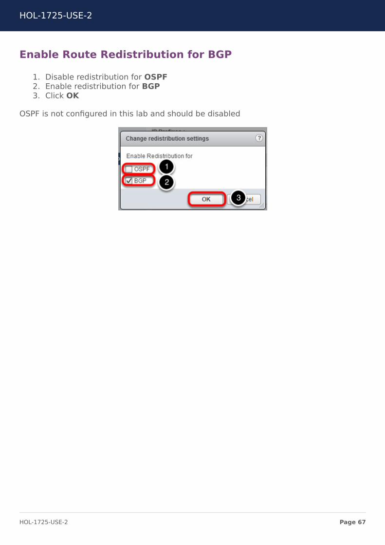
Enable Route Redistribution for BGP
1. Disable redistribution for OSPF2. Enable redistribution for BGP3. Click OK
OSPF is not configured in this lab and should be disabled
HOL-1725-USE-2
Page 67HOL-1725-USE-2
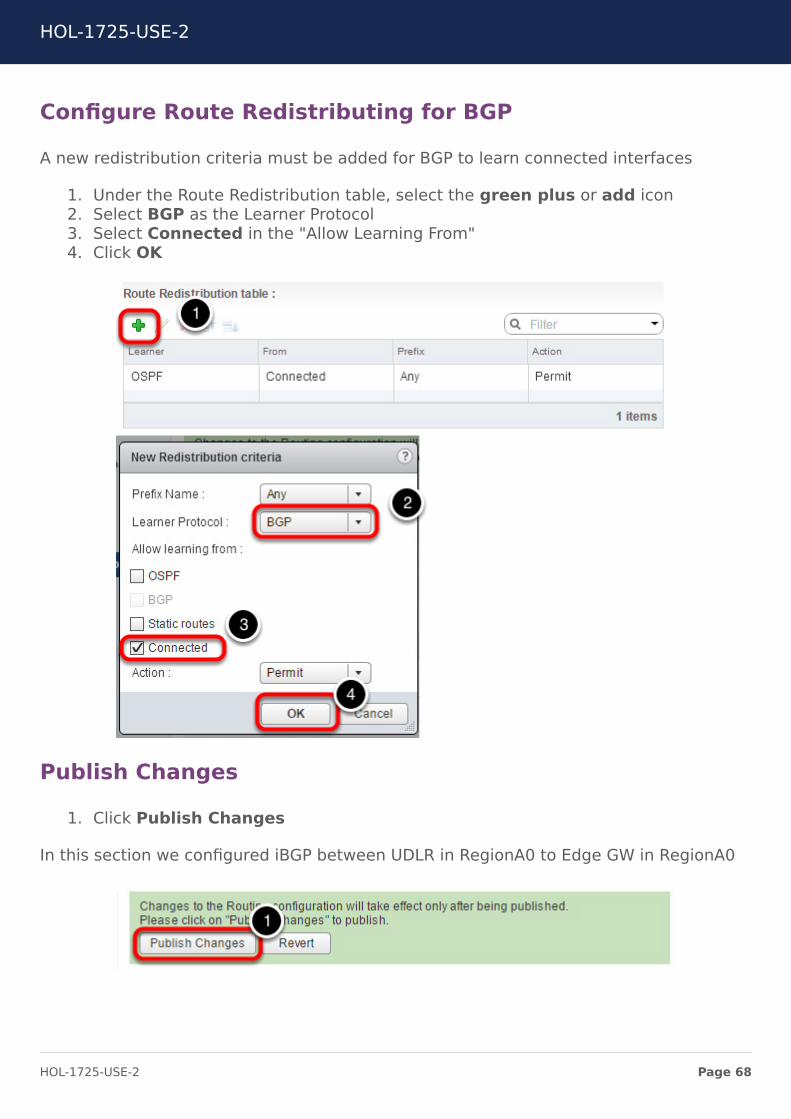
Configure Route Redistributing for BGP
A new redistribution criteria must be added for BGP to learn connected interfaces
1. Under the Route Redistribution table, select the green plus or add icon2. Select BGP as the Learner Protocol3. Select Connected in the "Allow Learning From"4. Click OK
Publish Changes
1. Click Publish Changes
In this section we configured iBGP between UDLR in RegionA0 to Edge GW in RegionA0
HOL-1725-USE-2
Page 68HOL-1725-USE-2
Enable BGP on Universal LogicalRouter RegionB0You will now configure BGP on the Universal Logical Distributed Router.
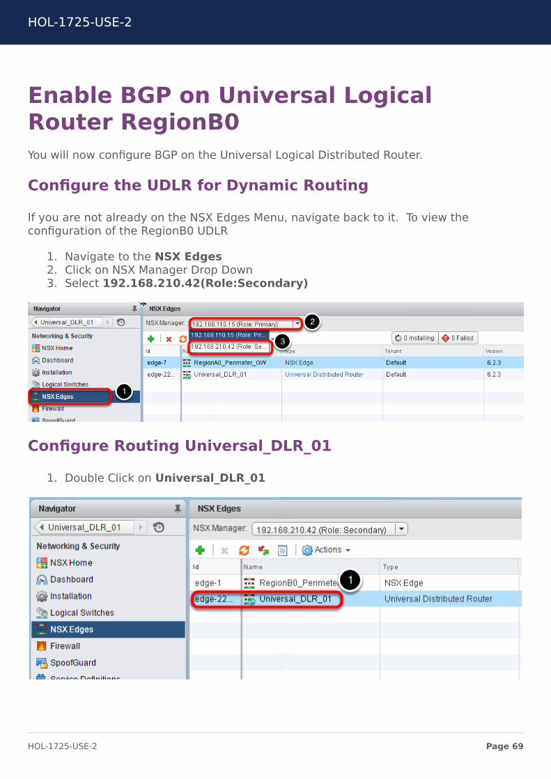
Configure the UDLR for Dynamic Routing
If you are not already on the NSX Edges Menu, navigate back to it. To view theconfiguration of the RegionB0 UDLR
1. Navigate to the NSX Edges2. Click on NSX Manager Drop Down3. Select 192.168.210.42(Role:Secondary)
Configure Routing Universal_DLR_01
1. Double Click on Universal_DLR_01
HOL-1725-USE-2
Page 69HOL-1725-USE-2
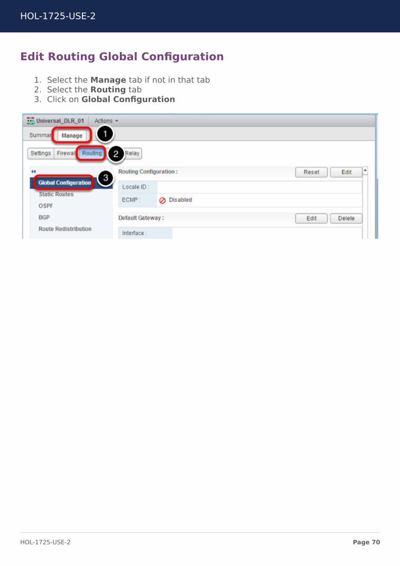
Edit Routing Global Configuration
1. Select the Manage tab if not in that tab2. Select the Routing tab3. Click on Global Configuration
HOL-1725-USE-2
Page 70HOL-1725-USE-2
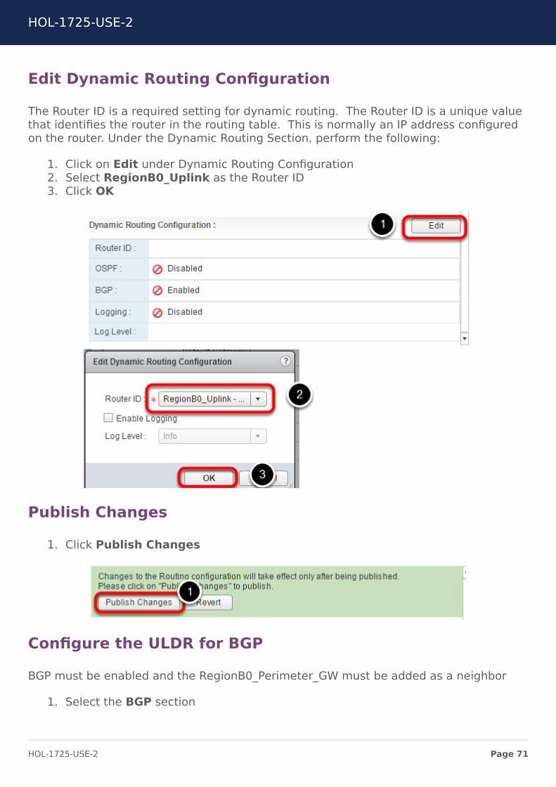
Edit Dynamic Routing Configuration
The Router ID is a required setting for dynamic routing. The Router ID is a unique valuethat identifies the router in the routing table. This is normally an IP address configuredon the router. Under the Dynamic Routing Section, perform the following:
1. Click on Edit under Dynamic Routing Configuration2. Select RegionB0_Uplink as the Router ID3. Click OK
Publish Changes
1. Click Publish Changes
Configure the ULDR for BGP
BGP must be enabled and the RegionB0_Perimeter_GW must be added as a neighbor
1. Select the BGP section
HOL-1725-USE-2
Page 71HOL-1725-USE-2
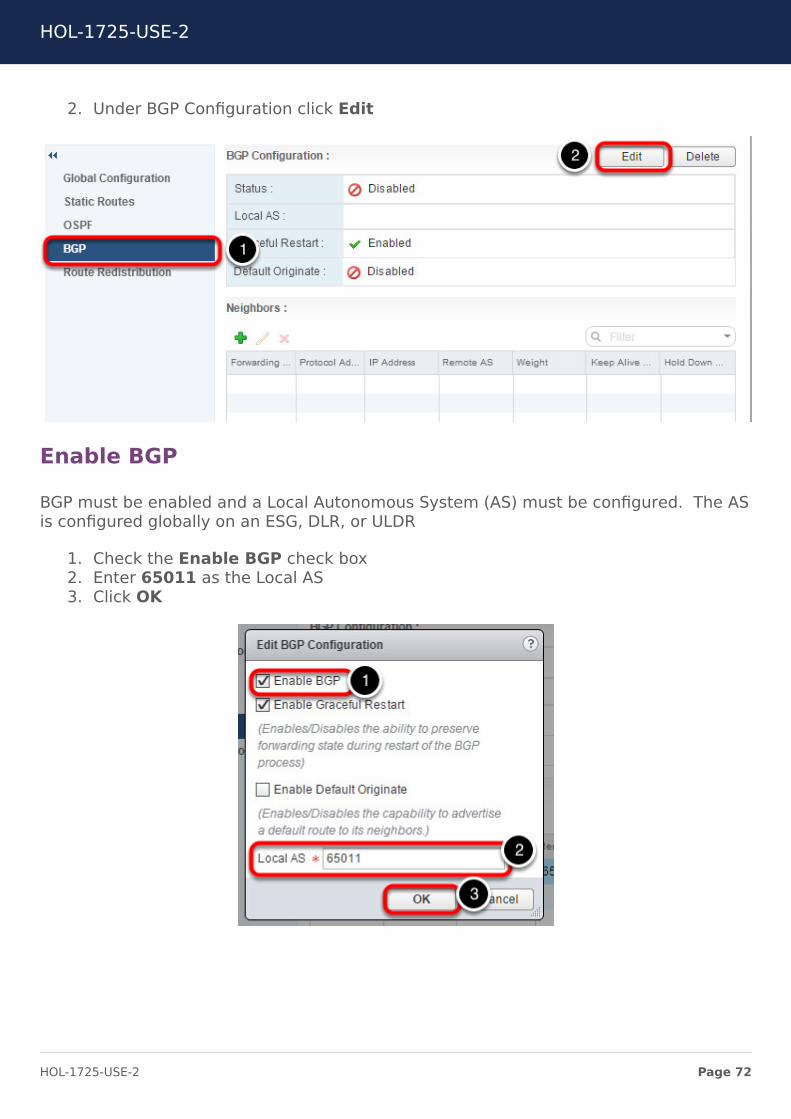
2. Under BGP Configuration click Edit
Enable BGP
BGP must be enabled and a Local Autonomous System (AS) must be configured. The ASis configured globally on an ESG, DLR, or ULDR
1. Check the Enable BGP check box2. Enter 65011 as the Local AS3. Click OK
HOL-1725-USE-2
Page 72HOL-1725-USE-2
Add a Neighbor
Add the RegionA0_Perimeter_GW as a Neighboor. The IP address is the IP of the internalinterface or the RegionA0_Perimeter_GW. The forwarding address is the IP address ofthe Universal_DLR RegionA0 uplink interface. The protocol address is an unused IPaddress in the same network as the forwarding address. The RegionA0_Perimeter_GWESG is configured with this address as a BGP neighboor. The forwarding address is usedas the data plane while the protocol address is used in the control plane.
1. Under the Neighbour Section, Click the Green Plus or add icon2. In the IP Address field, enter 192.168.5.93. In the Forwarding Address field, enter 192.168.5.104. In the Protocol Address field, enter 192.168.5.115. In the Remote AS field, enter 65011
Leave the other fields at their default values
6. Click OK
HOL-1725-USE-2
Page 73HOL-1725-USE-2
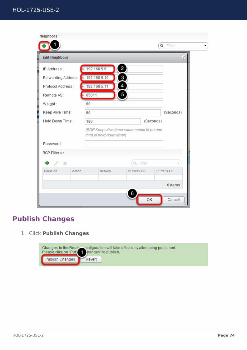
Publish Changes
1. Click Publish Changes
HOL-1725-USE-2
Page 74HOL-1725-USE-2

Enable Route Redistribution
Route Redistribution must be enabled on the ULDR for connected network to beadvertised via BGP.
1. Select the Route Redistribution section2. Click Edit
HOL-1725-USE-2
Page 75HOL-1725-USE-2
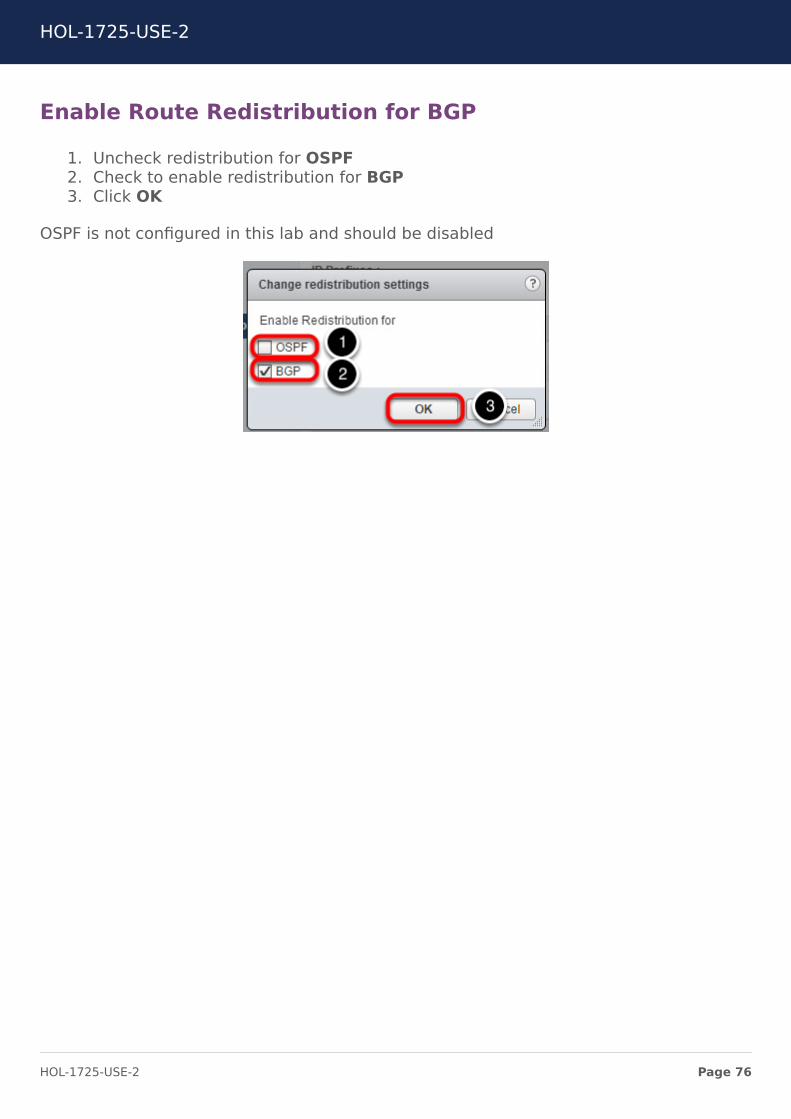
Enable Route Redistribution for BGP
1. Uncheck redistribution for OSPF2. Check to enable redistribution for BGP3. Click OK
OSPF is not configured in this lab and should be disabled
HOL-1725-USE-2
Page 76HOL-1725-USE-2
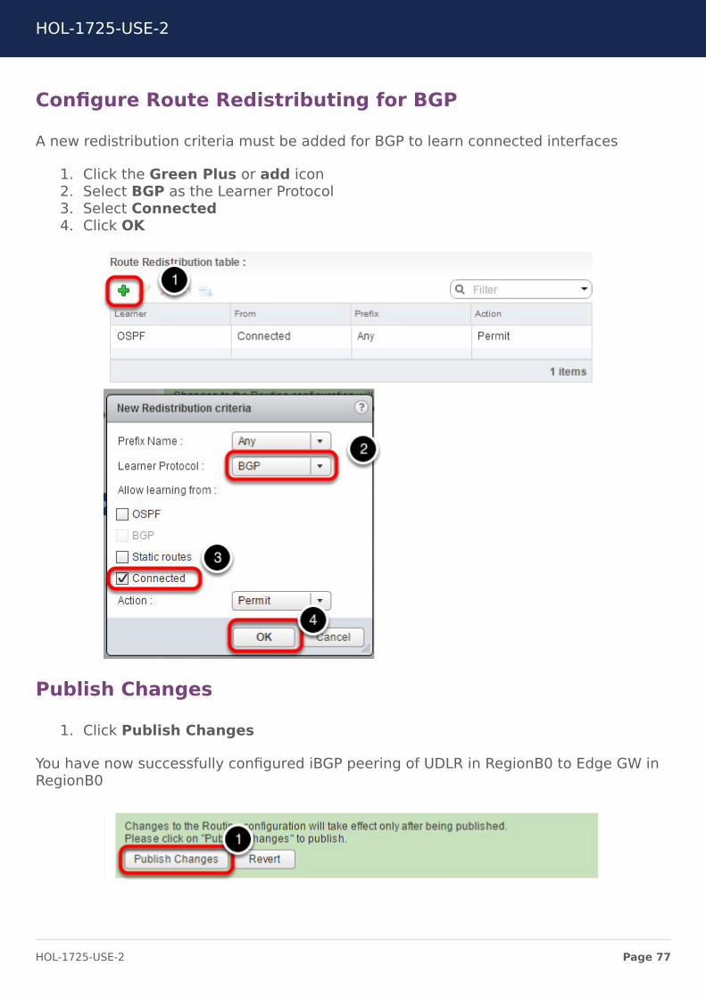
Configure Route Redistributing for BGP
A new redistribution criteria must be added for BGP to learn connected interfaces
1. Click the Green Plus or add icon2. Select BGP as the Learner Protocol3. Select Connected4. Click OK
Publish Changes
1. Click Publish Changes
You have now successfully configured iBGP peering of UDLR in RegionB0 to Edge GW inRegionB0
HOL-1725-USE-2
Page 77HOL-1725-USE-2
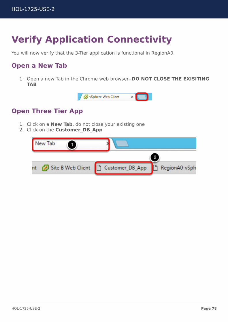
Verify Application ConnectivityYou will now verify that the 3-Tier application is functional in RegionA0.
Open a New Tab
1. Open a new Tab in the Chrome web browser--DO NOT CLOSE THE EXISITINGTAB
Open Three Tier App
1. Click on a New Tab, do not close your existing one2. Click on the Customer_DB_App
HOL-1725-USE-2
Page 78HOL-1725-USE-2
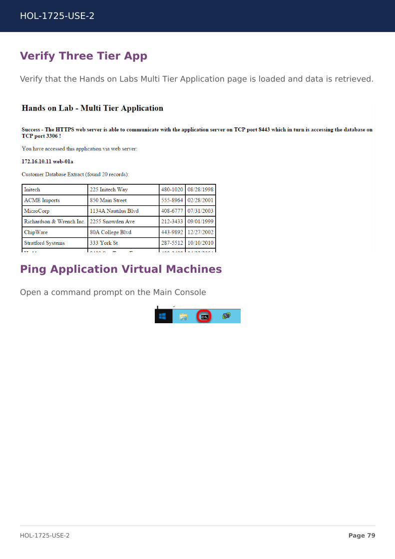
Verify Three Tier App
Verify that the Hands on Labs Multi Tier Application page is loaded and data is retrieved.
Ping Application Virtual Machines
Open a command prompt on the Main Console
HOL-1725-USE-2
Page 79HOL-1725-USE-2
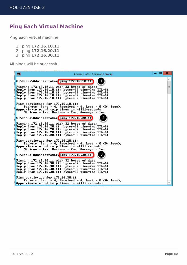
Ping Each Virtual Machine
Ping each virtual machine
1. ping 172.16.10.112. ping 172.16.20.113. ping 172.16.30.11
All pings will be successful
HOL-1725-USE-2
Page 80HOL-1725-USE-2
Create Universal Distributed FirewallRulesYou will now create Universal Distributed Firewall Rules for the Customer_DB_Appapplication. Universal Distributed Firewall Rules must only contain IP addresses, IP Sets,MAC addresses, or MAC Sets. Universal Distributed Firewall rules can span betweenvCenters in same Data Center or across multiple Data Centers. In this section. UniversalRules are created so that they can span between protected and recovery site.
Navigate to the vSphere Web Client
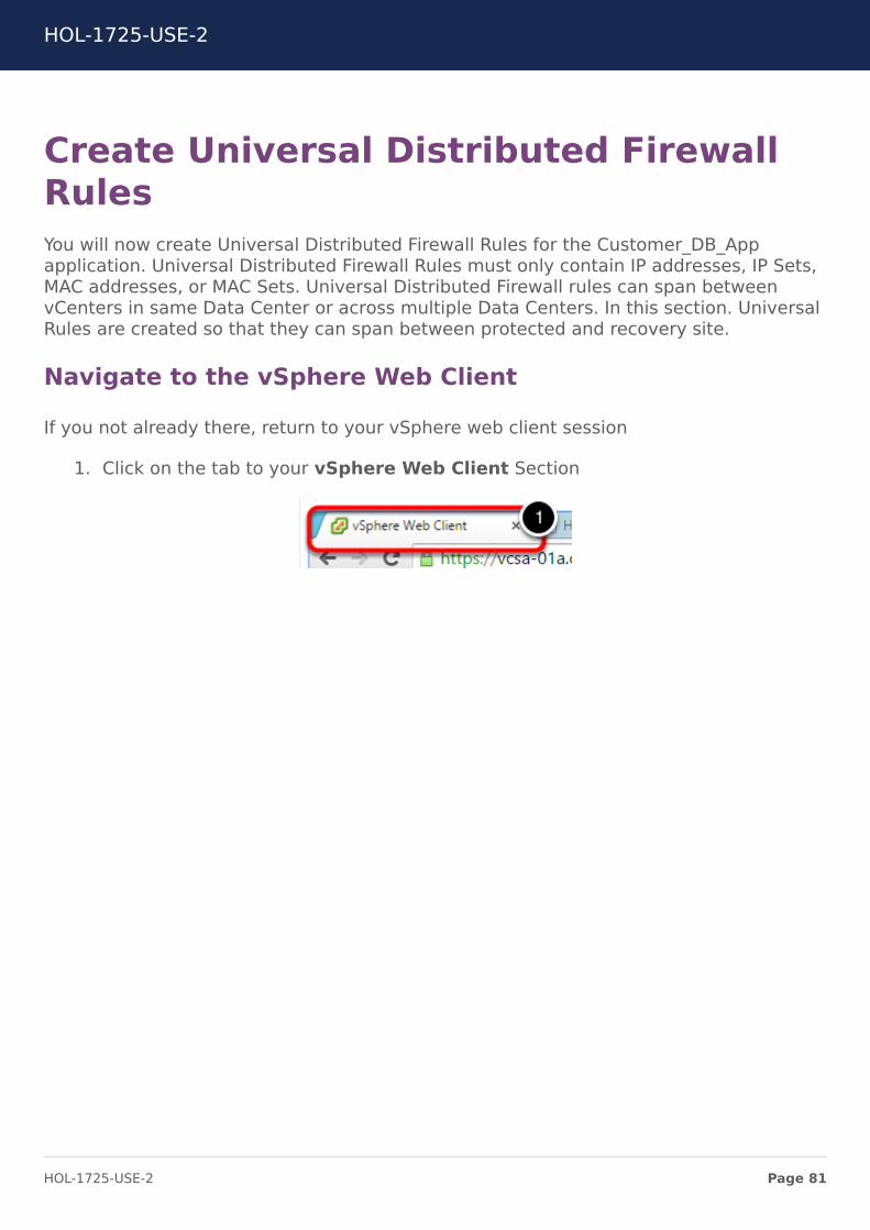
If you not already there, return to your vSphere web client session
1. Click on the tab to your vSphere Web Client Section
HOL-1725-USE-2
Page 81HOL-1725-USE-2
Navigate to the Networking & Security tab
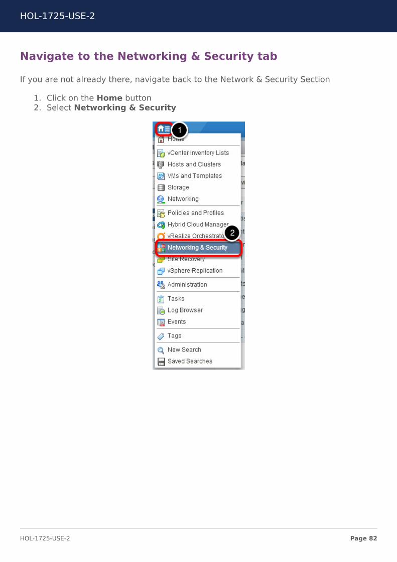
If you are not already there, navigate back to the Network & Security Section
1. Click on the Home button2. Select Networking & Security
HOL-1725-USE-2
Page 82HOL-1725-USE-2
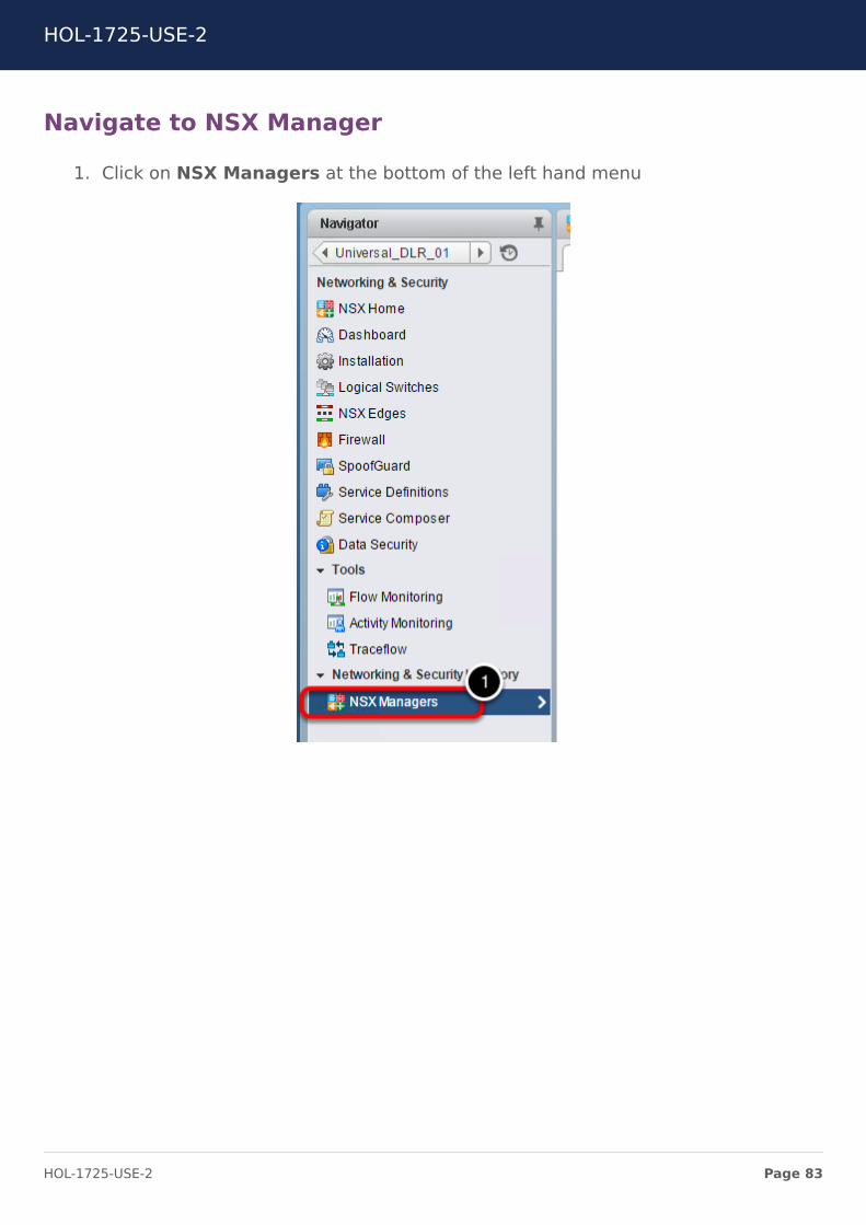
Navigate to NSX Manager
1. Click on NSX Managers at the bottom of the left hand menu
HOL-1725-USE-2
Page 83HOL-1725-USE-2
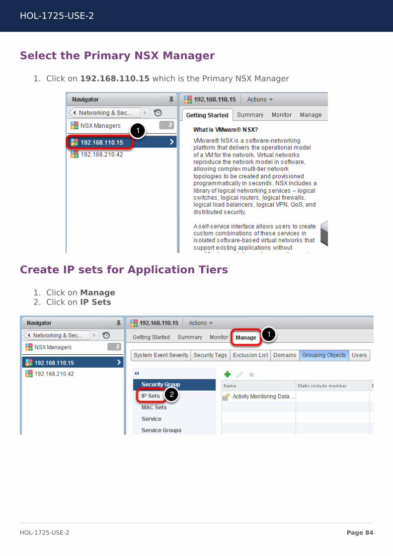
Select the Primary NSX Manager
1. Click on 192.168.110.15 which is the Primary NSX Manager
Create IP sets for Application Tiers
1. Click on Manage2. Click on IP Sets
HOL-1725-USE-2
Page 84HOL-1725-USE-2
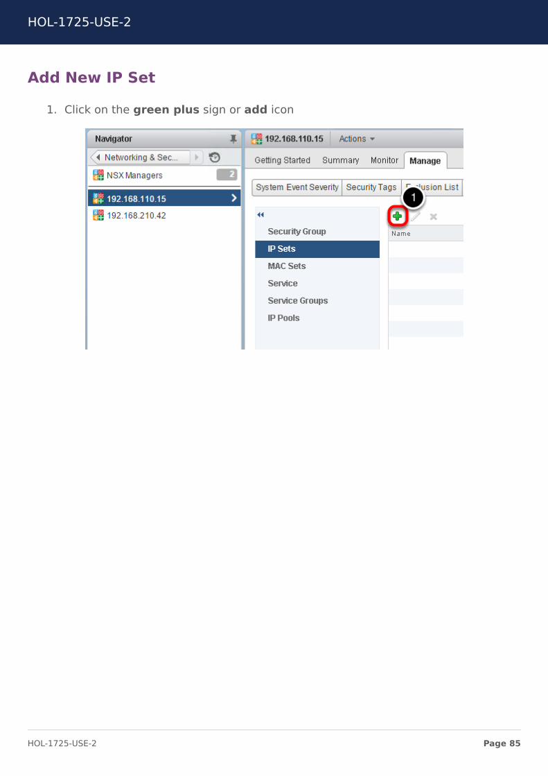
Add New IP Set
1. Click on the green plus sign or add icon
HOL-1725-USE-2
Page 85HOL-1725-USE-2
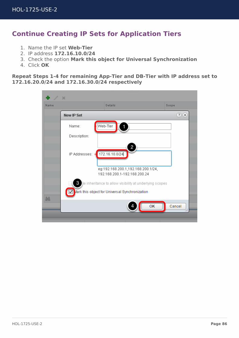
Continue Creating IP Sets for Application Tiers
1. Name the IP set Web-Tier2. IP address 172.16.10.0/243. Check the option Mark this object for Universal Synchronization4. Click OK
Repeat Steps 1-4 for remaining App-Tier and DB-Tier with IP address set to172.16.20.0/24 and 172.16.30.0/24 respectively
HOL-1725-USE-2
Page 86HOL-1725-USE-2

Verify Creation of IP Sets on Secondary NSX Manager
As soon as you create the IP Sets on Primary NSX manager, the Universal SyncronizationService will push the rules to the Secondary NSX manager. It is important to validatethat the synchronization is taking place across both NSX Managers. Validate the IP Setshave been created on the secondary manager by performing the following steps.
1. Click on 192.168.210.422. Verify creation of IP sets Web-Tier,App-Tier and DB-Tier
HOL-1725-USE-2
Page 87HOL-1725-USE-2
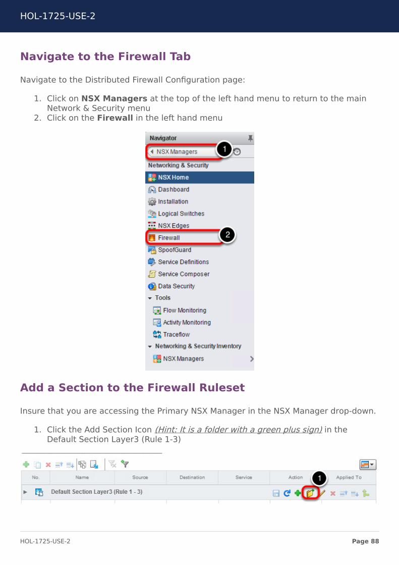
Navigate to the Firewall Tab
Navigate to the Distributed Firewall Configuration page:
1. Click on NSX Managers at the top of the left hand menu to return to the mainNetwork & Security menu
2. Click on the Firewall in the left hand menu
Add a Section to the Firewall Ruleset
Insure that you are accessing the Primary NSX Manager in the NSX Manager drop-down.
1. Click the Add Section Icon (Hint: It is a folder with a green plus sign) in theDefault Section Layer3 (Rule 1-3)
HOL-1725-USE-2
Page 88HOL-1725-USE-2

Create Section
1. Name the Section Three Tier App2. Select Mark this section for Universal Synchronization
Add a Universal Rule
In the newly created Section, add a place holder for a universal rule
1. Click the Add Rule icon (Hint: It is the green plus sign)
HOL-1725-USE-2
Page 89HOL-1725-USE-2
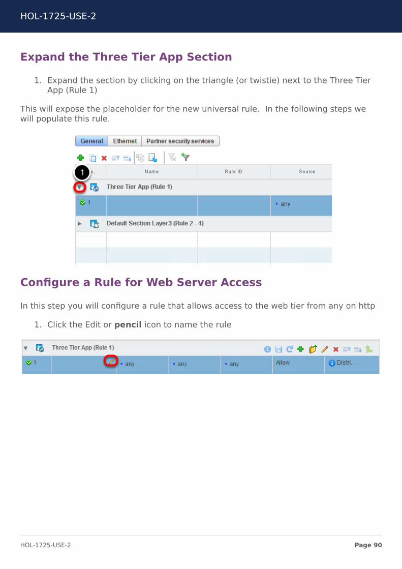
Expand the Three Tier App Section
1. Expand the section by clicking on the triangle (or twistie) next to the Three TierApp (Rule 1)
This will expose the placeholder for the new universal rule. In the following steps wewill populate this rule.
Configure a Rule for Web Server Access
In this step you will configure a rule that allows access to the web tier from any on http
1. Click the Edit or pencil icon to name the rule
HOL-1725-USE-2
Page 90HOL-1725-USE-2
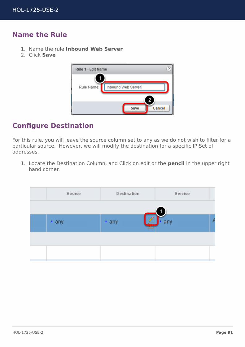
Name the Rule
1. Name the rule Inbound Web Server2. Click Save
Configure Destination
For this rule, you will leave the source column set to any as we do not wish to filter for aparticular source. However, we will modify the destination for a specific IP Set ofaddresses.
1. Locate the Destination Column, and Click on edit or the pencil in the upper righthand corner.
HOL-1725-USE-2
Page 91HOL-1725-USE-2
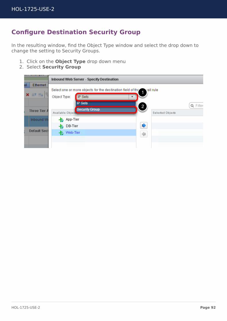
Configure Destination Security Group
In the resulting window, find the Object Type window and select the drop down tochange the setting to Security Groups.
1. Click on the Object Type drop down menu2. Select Security Group
HOL-1725-USE-2
Page 92HOL-1725-USE-2

Create a New Security Group
Once you have selected Security Group as an Object Type, you will see "New SecurityGroup" below Available Objects menu.
1. Click on New Security Group
HOL-1725-USE-2
Page 93HOL-1725-USE-2
Name the Security Group
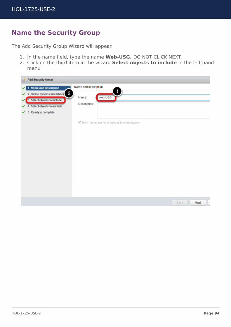
The Add Security Group Wizard will appear.
1. In the name field, type the name Web-USG. DO NOT CLICK NEXT.2. Click on the third item in the wizard Select objects to include in the left hand
menu
HOL-1725-USE-2
Page 94HOL-1725-USE-2

Include the IP Set
1. Click on Object Type drop down menu2. Select IP Sets in the drop down
HOL-1725-USE-2
Page 95HOL-1725-USE-2
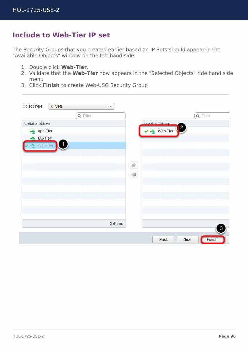
Include to Web-Tier IP set
The Security Groups that you created earlier based on IP Sets should appear in the"Available Objects" window on the left hand side.
1. Double click Web-Tier.2. Validate that the Web-Tier now appears in the "Selected Objects" ride hand side
menu3. Click Finish to create Web-USG Security Group
HOL-1725-USE-2
Page 96HOL-1725-USE-2
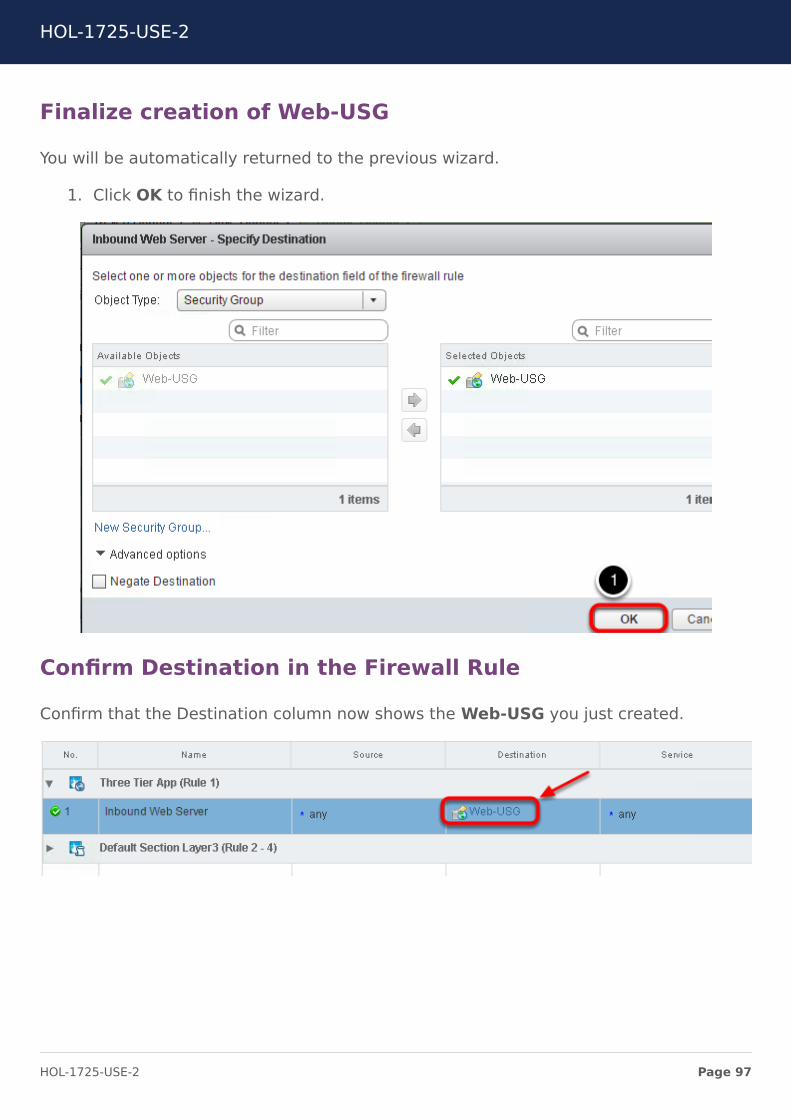
Finalize creation of Web-USG
You will be automatically returned to the previous wizard.
1. Click OK to finish the wizard.
Confirm Destination in the Firewall Rule
Confirm that the Destination column now shows the Web-USG you just created.
HOL-1725-USE-2
Page 97HOL-1725-USE-2
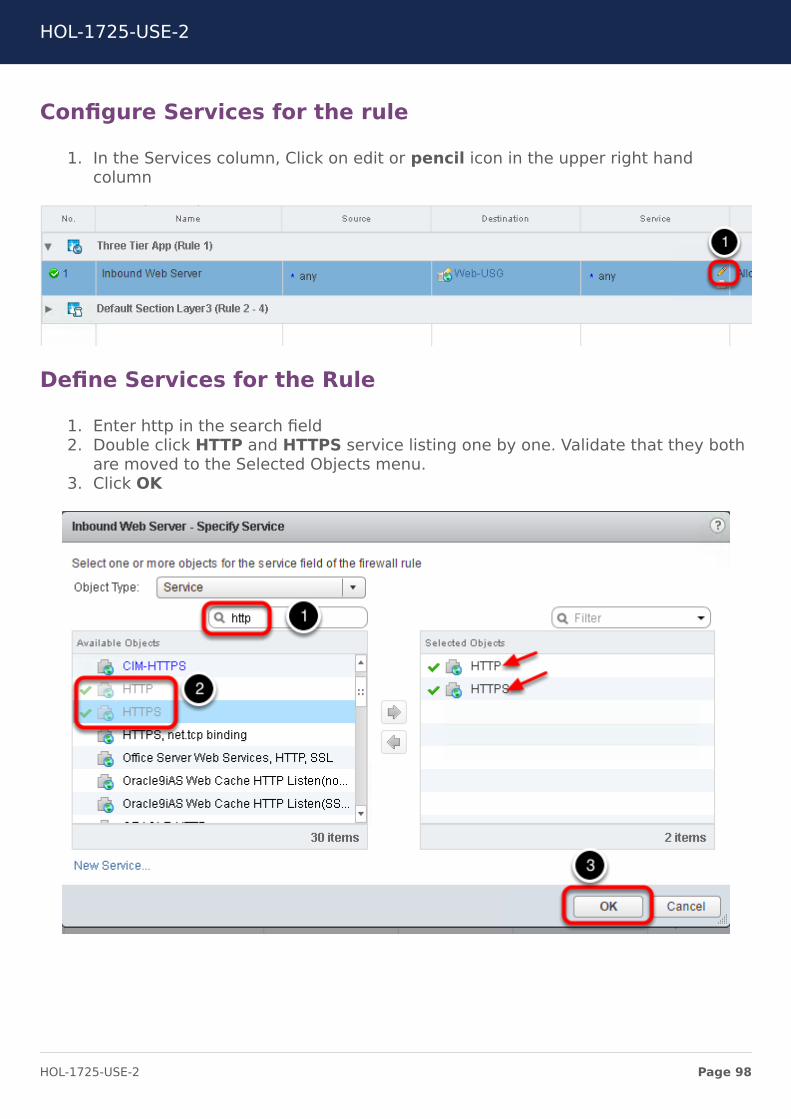
Configure Services for the rule
1. In the Services column, Click on edit or pencil icon in the upper right handcolumn
Define Services for the Rule
1. Enter http in the search field2. Double click HTTP and HTTPS service listing one by one. Validate that they both
are moved to the Selected Objects menu.3. Click OK
HOL-1725-USE-2
Page 98HOL-1725-USE-2
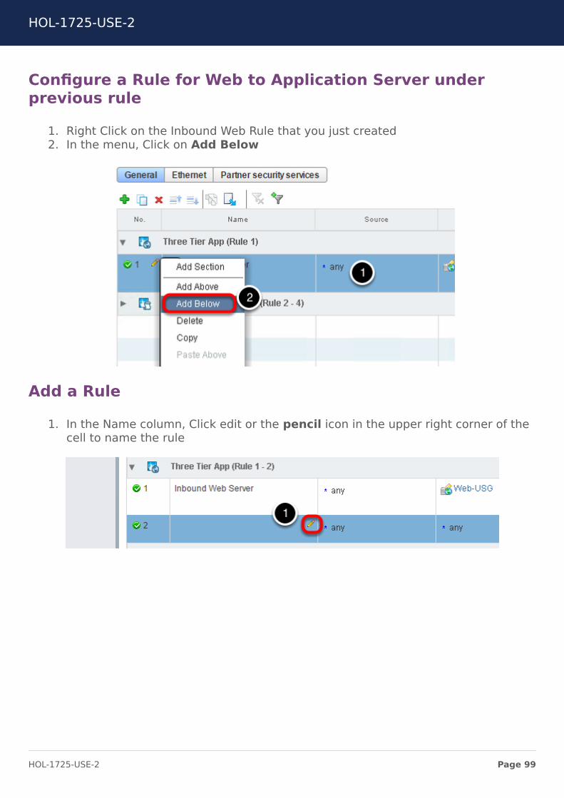
Configure a Rule for Web to Application Server underprevious rule
1. Right Click on the Inbound Web Rule that you just created2. In the menu, Click on Add Below
Add a Rule
1. In the Name column, Click edit or the pencil icon in the upper right corner of thecell to name the rule
HOL-1725-USE-2
Page 99HOL-1725-USE-2
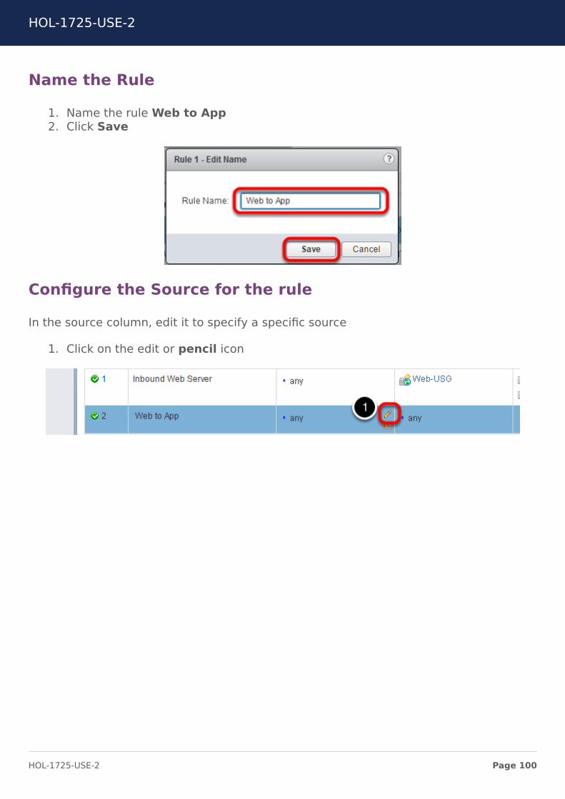
Name the Rule
1. Name the rule Web to App2. Click Save
Configure the Source for the rule
In the source column, edit it to specify a specific source
1. Click on the edit or pencil icon
HOL-1725-USE-2
Page 100HOL-1725-USE-2
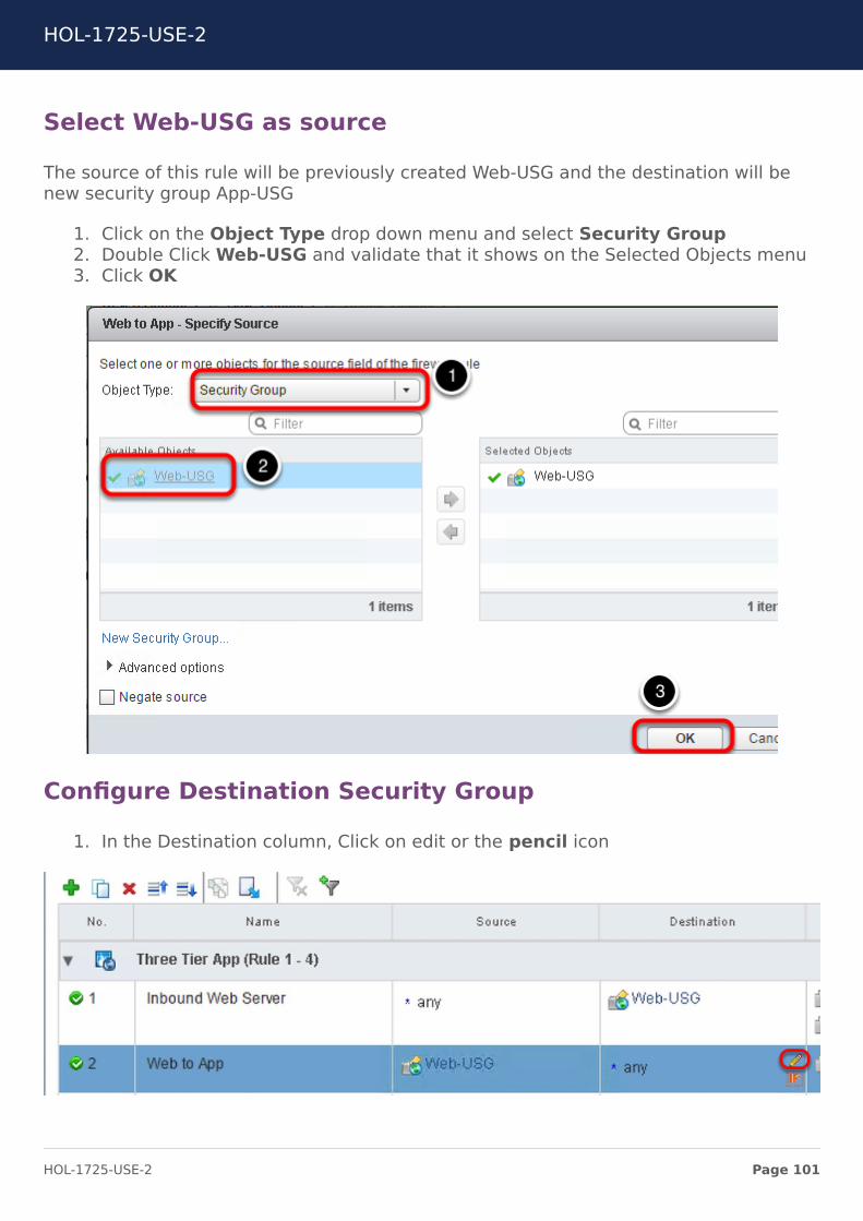
Select Web-USG as source
The source of this rule will be previously created Web-USG and the destination will benew security group App-USG
1. Click on the Object Type drop down menu and select Security Group2. Double Click Web-USG and validate that it shows on the Selected Objects menu3. Click OK
Configure Destination Security Group
1. In the Destination column, Click on edit or the pencil icon
HOL-1725-USE-2
Page 101HOL-1725-USE-2
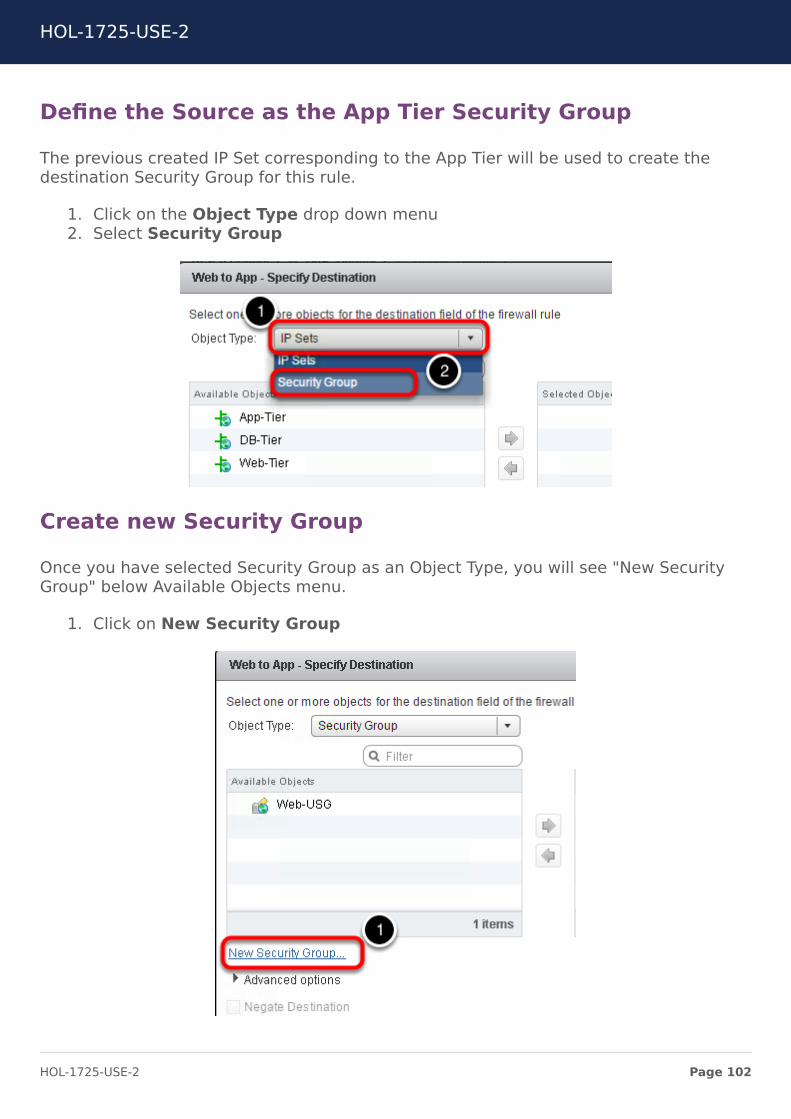
Define the Source as the App Tier Security Group
The previous created IP Set corresponding to the App Tier will be used to create thedestination Security Group for this rule.
1. Click on the Object Type drop down menu2. Select Security Group
Create new Security Group
Once you have selected Security Group as an Object Type, you will see "New SecurityGroup" below Available Objects menu.
1. Click on New Security Group
HOL-1725-USE-2
Page 102HOL-1725-USE-2
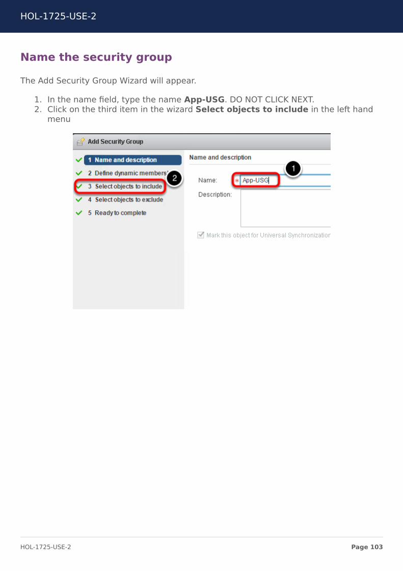
Name the security group
The Add Security Group Wizard will appear.
1. In the name field, type the name App-USG. DO NOT CLICK NEXT.2. Click on the third item in the wizard Select objects to include in the left hand
menu
HOL-1725-USE-2
Page 103HOL-1725-USE-2
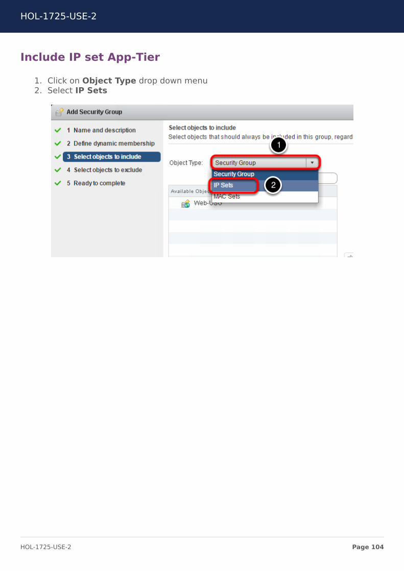
Include IP set App-Tier
1. Click on Object Type drop down menu2. Select IP Sets
HOL-1725-USE-2
Page 104HOL-1725-USE-2
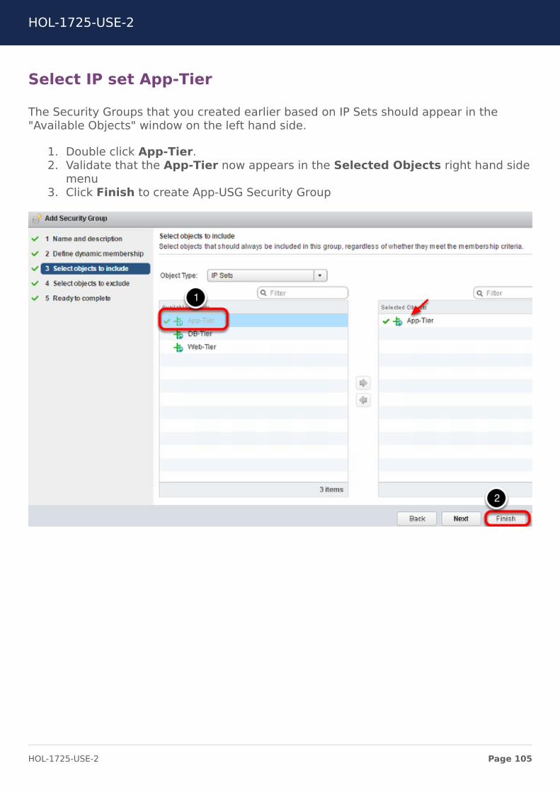
Select IP set App-Tier
The Security Groups that you created earlier based on IP Sets should appear in the"Available Objects" window on the left hand side.
1. Double click App-Tier.2. Validate that the App-Tier now appears in the Selected Objects right hand side
menu3. Click Finish to create App-USG Security Group
HOL-1725-USE-2
Page 105HOL-1725-USE-2
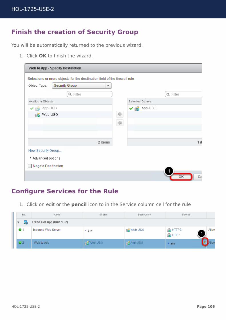
Finish the creation of Security Group
You will be automatically returned to the previous wizard.
1. Click OK to finish the wizard.
Configure Services for the Rule
1. Click on edit or the pencil icon to in the Service column cell for the rule
HOL-1725-USE-2
Page 106HOL-1725-USE-2
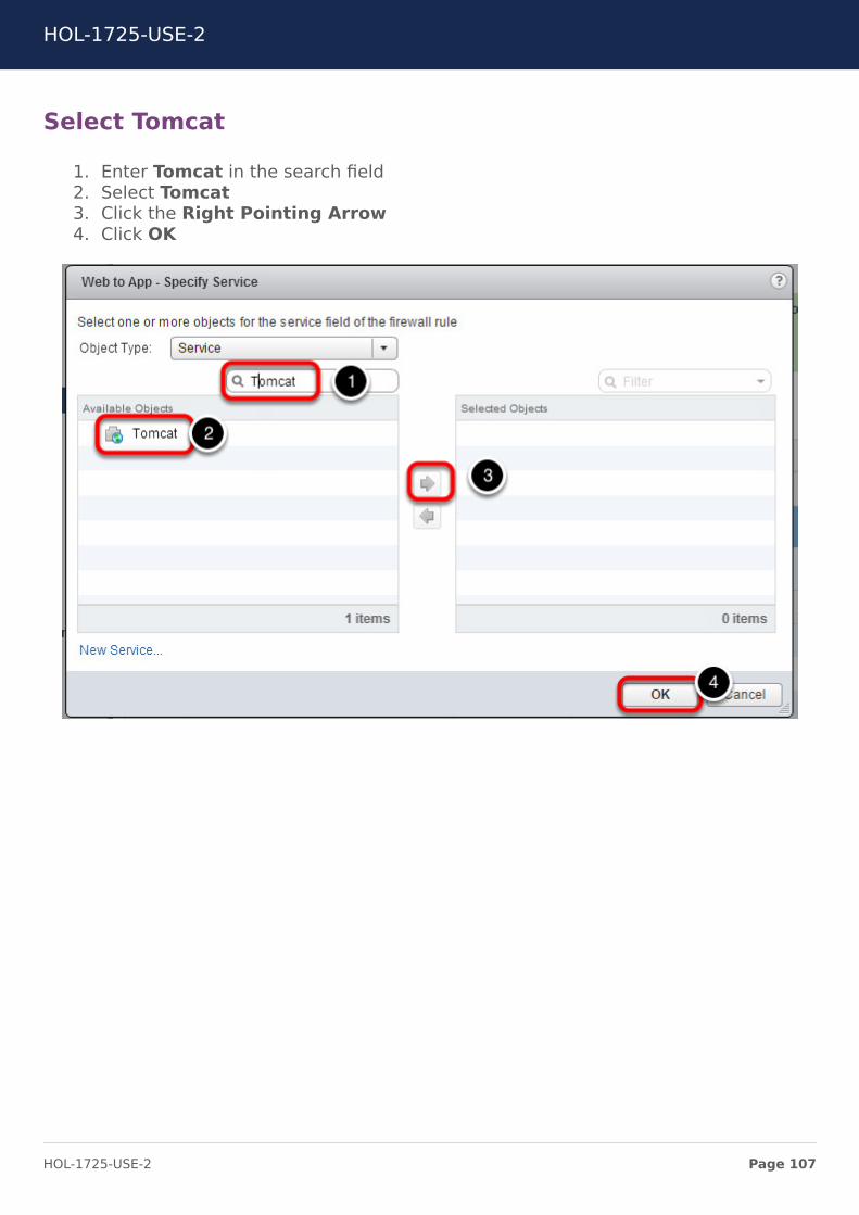
Select Tomcat
1. Enter Tomcat in the search field2. Select Tomcat3. Click the Right Pointing Arrow4. Click OK
HOL-1725-USE-2
Page 107HOL-1725-USE-2
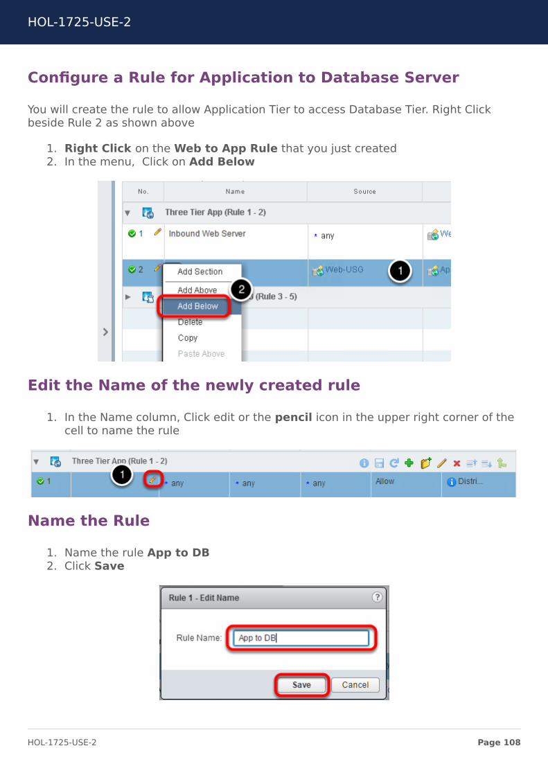
Configure a Rule for Application to Database Server
You will create the rule to allow Application Tier to access Database Tier. Right Clickbeside Rule 2 as shown above
1. Right Click on the Web to App Rule that you just created2. In the menu, Click on Add Below
Edit the Name of the newly created rule
1. In the Name column, Click edit or the pencil icon in the upper right corner of thecell to name the rule
Name the Rule
1. Name the rule App to DB2. Click Save
HOL-1725-USE-2
Page 108HOL-1725-USE-2
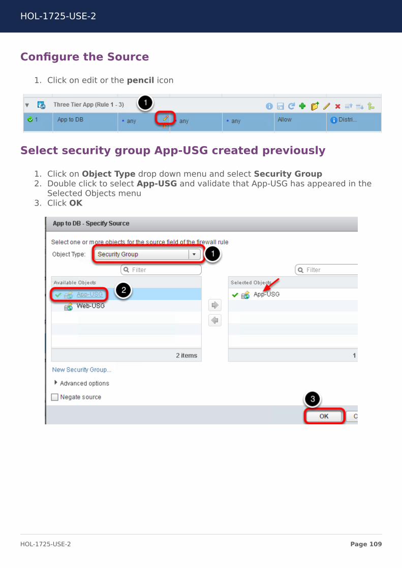
Configure the Source
1. Click on edit or the pencil icon
Select security group App-USG created previously
1. Click on Object Type drop down menu and select Security Group2. Double click to select App-USG and validate that App-USG has appeared in the
Selected Objects menu3. Click OK
HOL-1725-USE-2
Page 109HOL-1725-USE-2
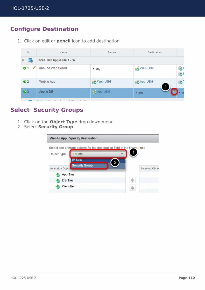
Configure Destination
1. Click on edit or pencil icon to add destination
Select Security Groups
1. Click on the Object Type drop down menu2. Select Security Group
HOL-1725-USE-2
Page 110HOL-1725-USE-2
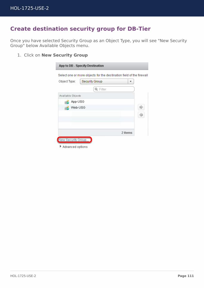
Create destination security group for DB-Tier
Once you have selected Security Group as an Object Type, you will see "New SecurityGroup" below Available Objects menu.
1. Click on New Security Group
HOL-1725-USE-2
Page 111HOL-1725-USE-2
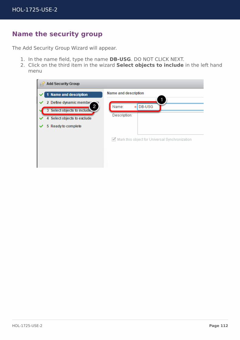
Name the security group
The Add Security Group Wizard will appear.
1. In the name field, type the name DB-USG. DO NOT CLICK NEXT.2. Click on the third item in the wizard Select objects to include in the left hand
menu
HOL-1725-USE-2
Page 112HOL-1725-USE-2
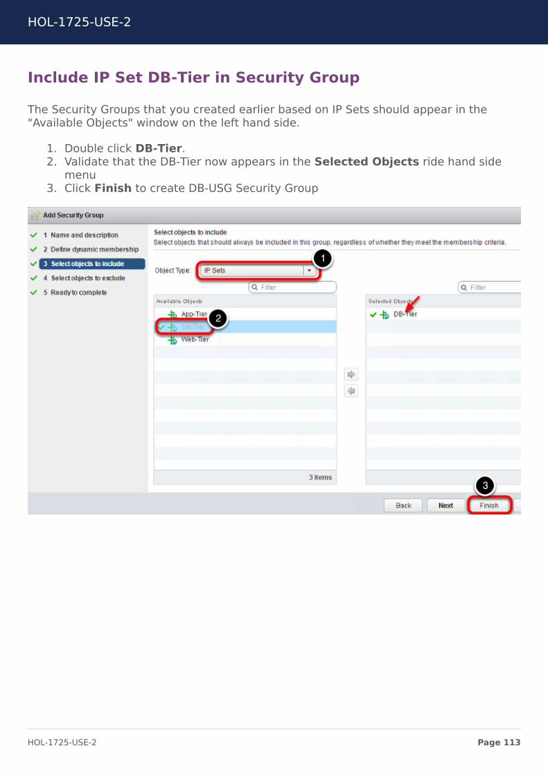
Include IP Set DB-Tier in Security Group
The Security Groups that you created earlier based on IP Sets should appear in the"Available Objects" window on the left hand side.
1. Double click DB-Tier.2. Validate that the DB-Tier now appears in the Selected Objects ride hand side
menu3. Click Finish to create DB-USG Security Group
HOL-1725-USE-2
Page 113HOL-1725-USE-2

Finish the creation of security group
You will be automatically returned to the previous wizard.
1. Click OK to finish the wizard.
Configure Service
1. Click on edit or the pencil icon in the Service column cell for the rule
Select MySQL
1. Enter MySQL in the search field
HOL-1725-USE-2
Page 114HOL-1725-USE-2
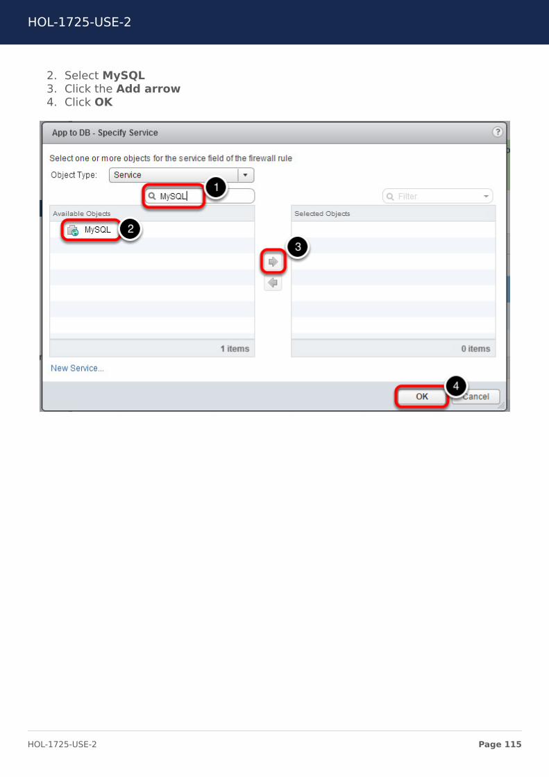
2. Select MySQL3. Click the Add arrow4. Click OK
HOL-1725-USE-2
Page 115HOL-1725-USE-2
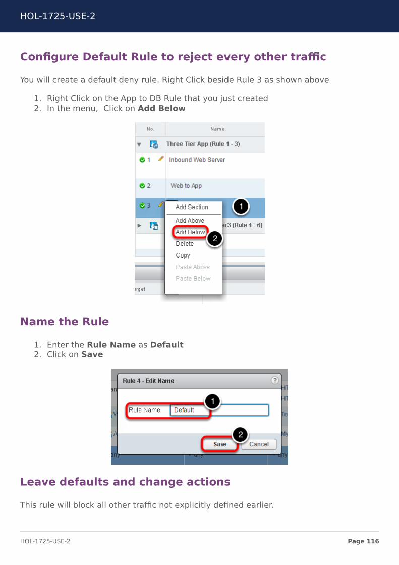
Configure Default Rule to reject every other traffic
You will create a default deny rule. Right Click beside Rule 3 as shown above
1. Right Click on the App to DB Rule that you just created2. In the menu, Click on Add Below
Name the Rule
1. Enter the Rule Name as Default2. Click on Save
Leave defaults and change actions
This rule will block all other traffic not explicitly defined earlier.
HOL-1725-USE-2
Page 116HOL-1725-USE-2
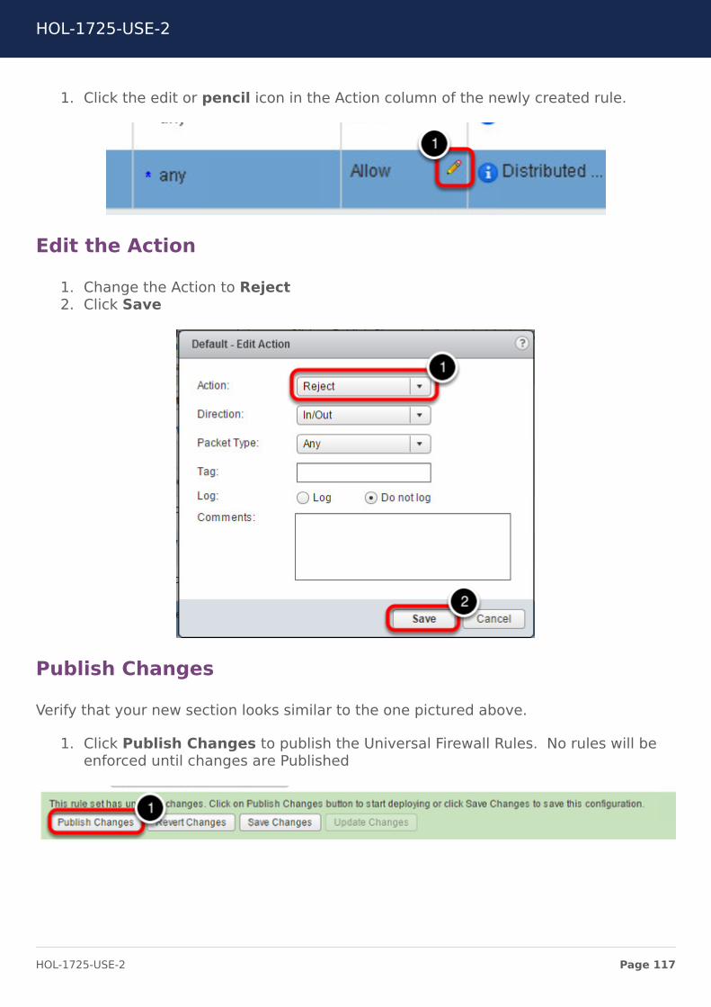
1. Click the edit or pencil icon in the Action column of the newly created rule.
Edit the Action
1. Change the Action to Reject2. Click Save
Publish Changes
Verify that your new section looks similar to the one pictured above.
1. Click Publish Changes to publish the Universal Firewall Rules. No rules will beenforced until changes are Published
HOL-1725-USE-2
Page 117HOL-1725-USE-2
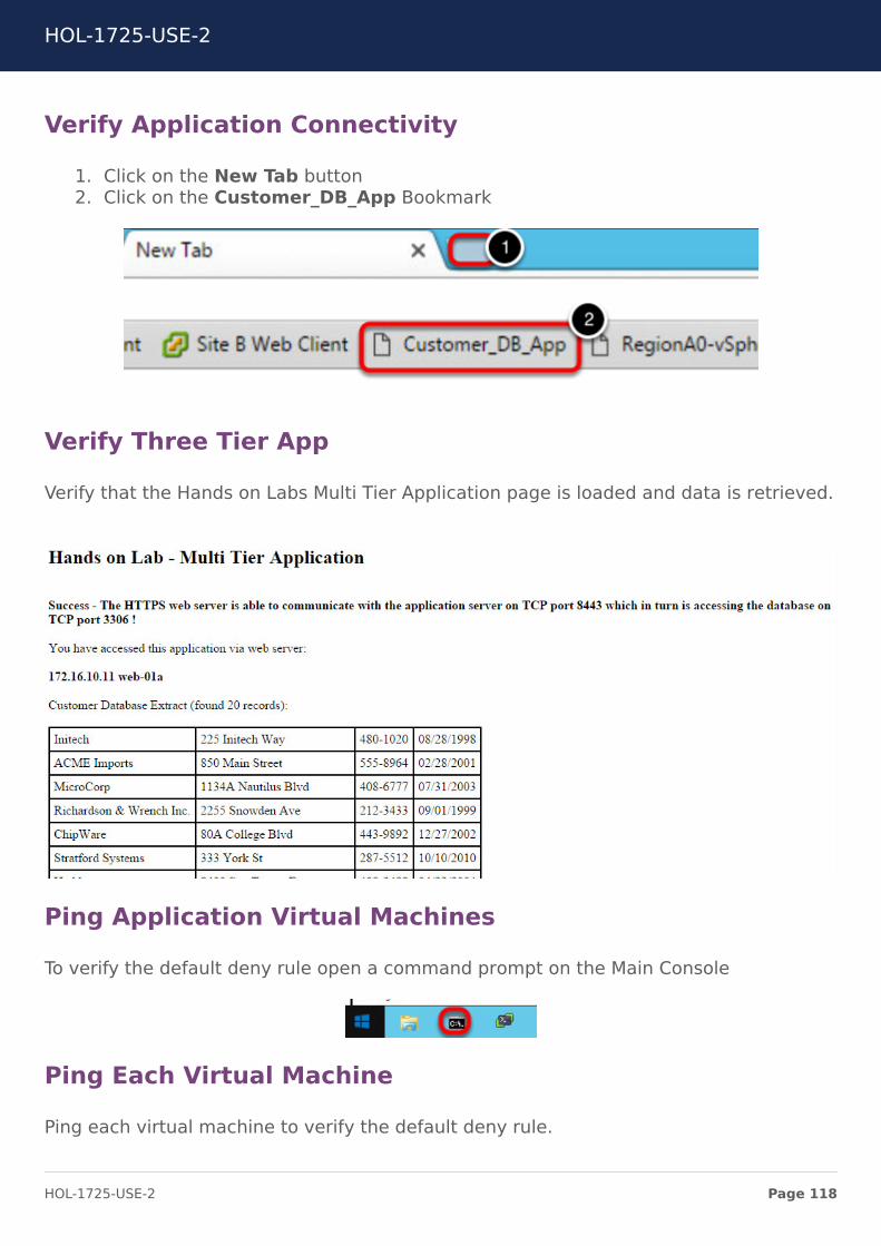
Verify Application Connectivity
1. Click on the New Tab button2. Click on the Customer_DB_App Bookmark
Verify Three Tier App
Verify that the Hands on Labs Multi Tier Application page is loaded and data is retrieved.
Ping Application Virtual Machines
To verify the default deny rule open a command prompt on the Main Console
Ping Each Virtual Machine
Ping each virtual machine to verify the default deny rule.
HOL-1725-USE-2
Page 118HOL-1725-USE-2
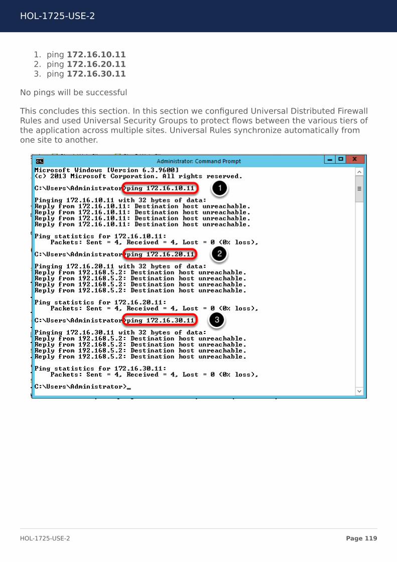
1. ping 172.16.10.112. ping 172.16.20.113. ping 172.16.30.11
No pings will be successful
This concludes this section. In this section we configured Universal Distributed FirewallRules and used Universal Security Groups to protect flows between the various tiers ofthe application across multiple sites. Universal Rules synchronize automatically fromone site to another.
HOL-1725-USE-2
Page 119HOL-1725-USE-2

Module 1 ConclusionThis module walked you through the various pre-configured components of NSX in amulti-site configuration. You also learned how to configure Locale ID, dynamic routing onUDLR,configuring Universal Distributed Firewall rules and route filtering for making onesite preferred over another. The techniques used in this module are not the only wayyou can influence ingress/egress traffic. There are other ways to do it and we showedyou one of the popular way to do it.
You've finished Module 1
Congratulations on completing Module 1. You can proceed to Module 2 for configuringthe SRM and performing partial and full failover of the application or End the Lab.Process to end the lab is described in "How to End Lab" section.
For additional information on NSX Universal configurations and cross vC scenarios, visitthe URL below and select the Cross-vCenter Installation Guide:
• Go to https://communities.vmware.com/docs/DOC-32552
Lab Captain:
• Module 1 - 2 Dev Sharma, Staff Systems Engineer-Canada
How to End Lab
To end the lab click on the END button.
HOL-1725-USE-2
Page 120HOL-1725-USE-2
Module 2 - Site RecoveryManager Configuration
(45 Minutes)
HOL-1725-USE-2
Page 121HOL-1725-USE-2
Module GuidanceIn this module, students will learn how to configure the important SRM components suchas Protection Groups, Folder Mappings, Resource Mappings, Recovery Plans, etc. Inaddition to configuring these various components, students will perform partial failoverand full failover of the application.
IMPORTANT NOTE: IF YOU ARE TAKING MODULE 2 WITHOUT FIRSTCOMPLETING MODULE 1, THEN YOU MUST EXECUTE THE SCRIPT DETAILEDBELOW.
If you have already completed Module 1, then you can skip the next step and proceed to"Creating SRM Protection Groups for Application".
HOL-1725-USE-2
Page 122HOL-1725-USE-2
Running the SRM FastForward Script
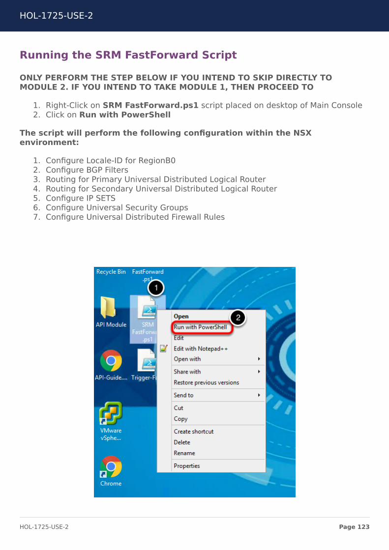
ONLY PERFORM THE STEP BELOW IF YOU INTEND TO SKIP DIRECTLY TOMODULE 2. IF YOU INTEND TO TAKE MODULE 1, THEN PROCEED TO
1. Right-Click on SRM FastForward.ps1 script placed on desktop of Main Console2. Click on Run with PowerShell
The script will perform the following configuration within the NSXenvironment:
1. Configure Locale-ID for RegionB02. Configure BGP Filters3. Routing for Primary Universal Distributed Logical Router4. Routing for Secondary Universal Distributed Logical Router5. Configure IP SETS6. Configure Universal Security Groups7. Configure Universal Distributed Firewall Rules
HOL-1725-USE-2
Page 123HOL-1725-USE-2
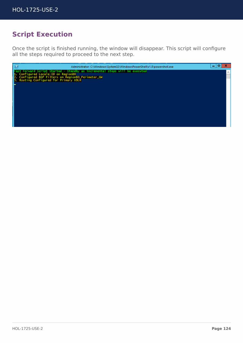
Script Execution
Once the script is finished running, the window will disappear. This script will configureall the steps required to proceed to the next step.
HOL-1725-USE-2
Page 124HOL-1725-USE-2
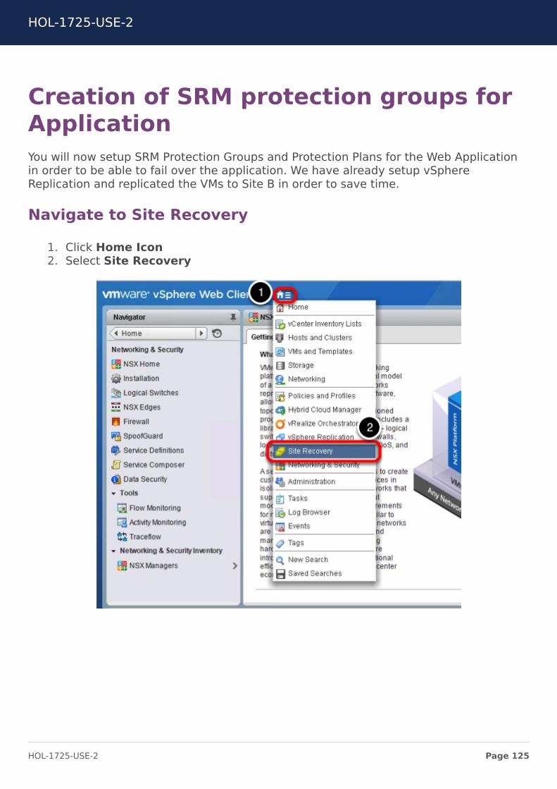
Creation of SRM protection groups forApplicationYou will now setup SRM Protection Groups and Protection Plans for the Web Applicationin order to be able to fail over the application. We have already setup vSphereReplication and replicated the VMs to Site B in order to save time.
Navigate to Site Recovery
1. Click Home Icon2. Select Site Recovery
HOL-1725-USE-2
Page 125HOL-1725-USE-2
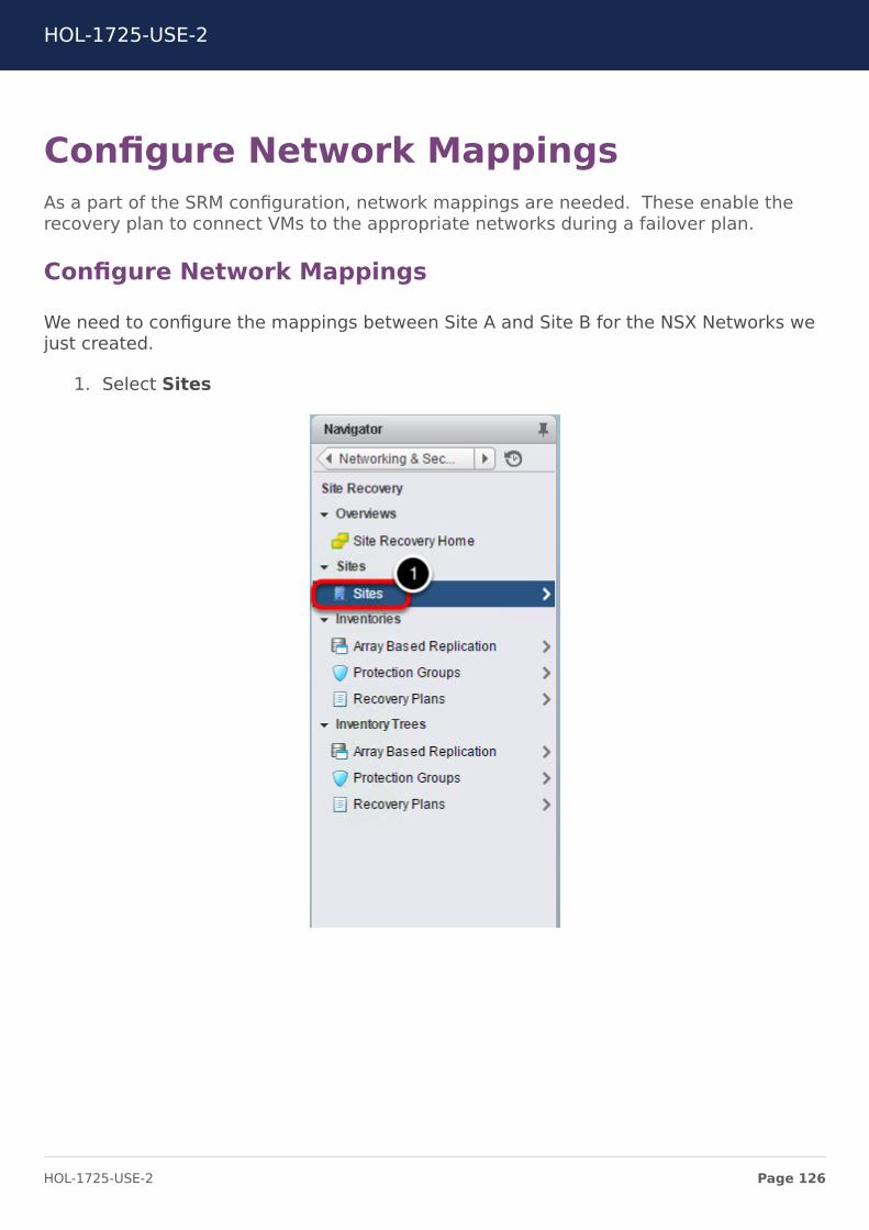
Configure Network MappingsAs a part of the SRM configuration, network mappings are needed. These enable therecovery plan to connect VMs to the appropriate networks during a failover plan.
Configure Network Mappings
We need to configure the mappings between Site A and Site B for the NSX Networks wejust created.
1. Select Sites
HOL-1725-USE-2
Page 126HOL-1725-USE-2
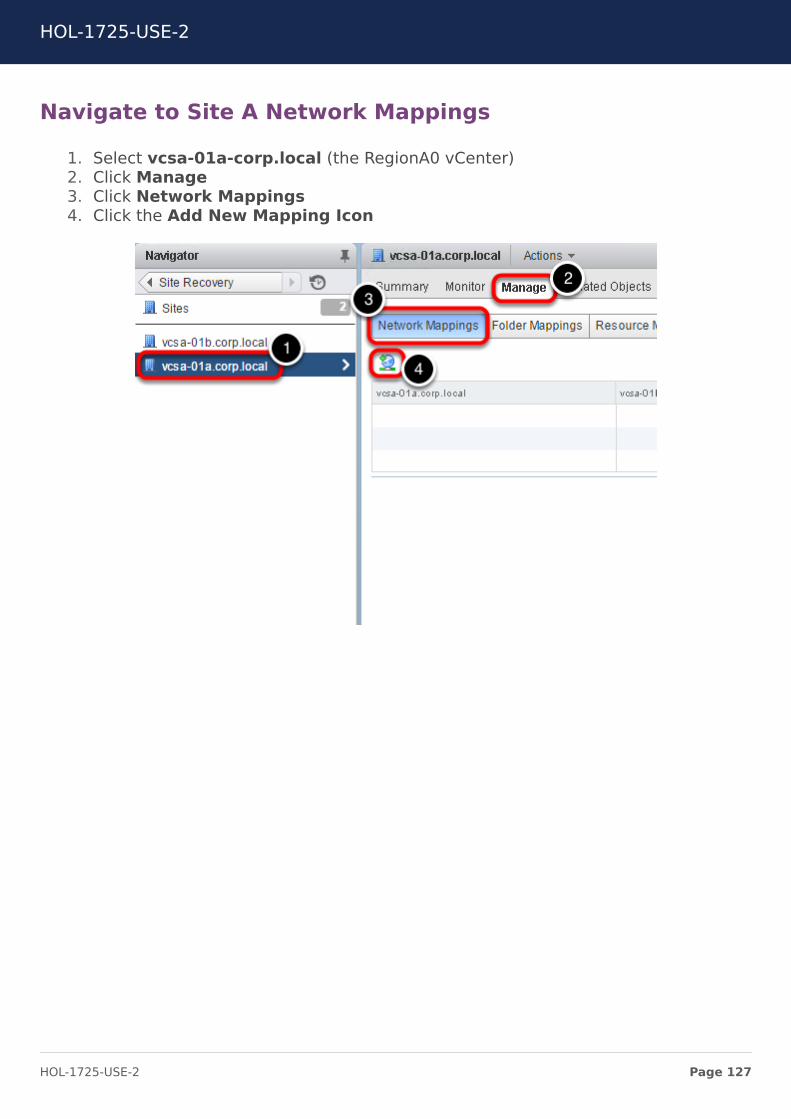
Navigate to Site A Network Mappings
1. Select vcsa-01a-corp.local (the RegionA0 vCenter)2. Click Manage3. Click Network Mappings4. Click the Add New Mapping Icon
HOL-1725-USE-2
Page 127HOL-1725-USE-2
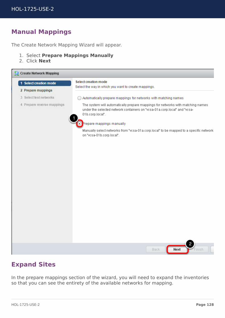
Manual Mappings
The Create Network Mapping Wizard will appear.
1. Select Prepare Mappings Manually2. Click Next
Expand Sites
In the prepare mappings section of the wizard, you will need to expand the inventoriesso that you can see the entirety of the available networks for mapping.
HOL-1725-USE-2
Page 128HOL-1725-USE-2
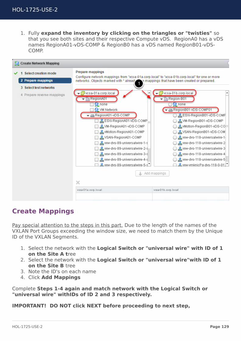
1. Fully expand the inventory by clicking on the triangles or "twisties" sothat you see both sites and their respective Compute vDS. RegionA0 has a vDSnames RegionA01-vDS-COMP & RegionB0 has a vDS named RegionB01-vDS-COMP.
Create Mappings
Pay special attention to the steps in this part. Due to the length of the names of theVXLAN Port Groups exceeding the window size, we need to match them by the UniqueID of the VXLAN Segments.
1. Select the network with the Logical Switch or "universal wire" with ID of 1on the Site A tree
2. Select the network with the Logical Switch or "universal wire"with ID of 1on the Site B tree
3. Note the ID's on each name4. Click Add Mappings
Complete Steps 1-4 again and match network with the Logical Switch or"universal wire" withIDs of ID 2 and 3 respectively.
IMPORTANT! DO NOT click NEXT before proceeding to next step,
HOL-1725-USE-2
Page 129HOL-1725-USE-2
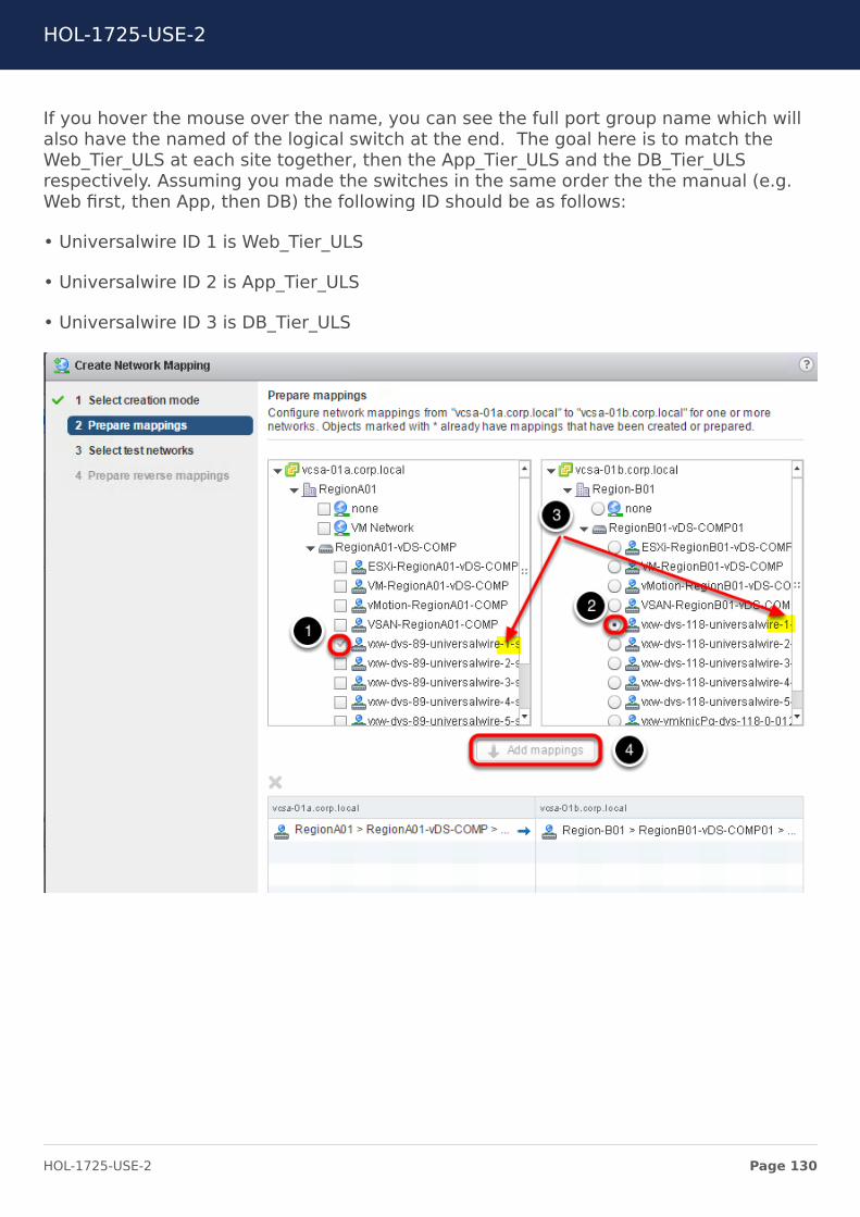
If you hover the mouse over the name, you can see the full port group name which willalso have the named of the logical switch at the end. The goal here is to match theWeb_Tier_ULS at each site together, then the App_Tier_ULS and the DB_Tier_ULSrespectively. Assuming you made the switches in the same order the the manual (e.g.Web first, then App, then DB) the following ID should be as follows:
• Universalwire ID 1 is Web_Tier_ULS
• Universalwire ID 2 is App_Tier_ULS
• Universalwire ID 3 is DB_Tier_ULS
HOL-1725-USE-2
Page 130HOL-1725-USE-2
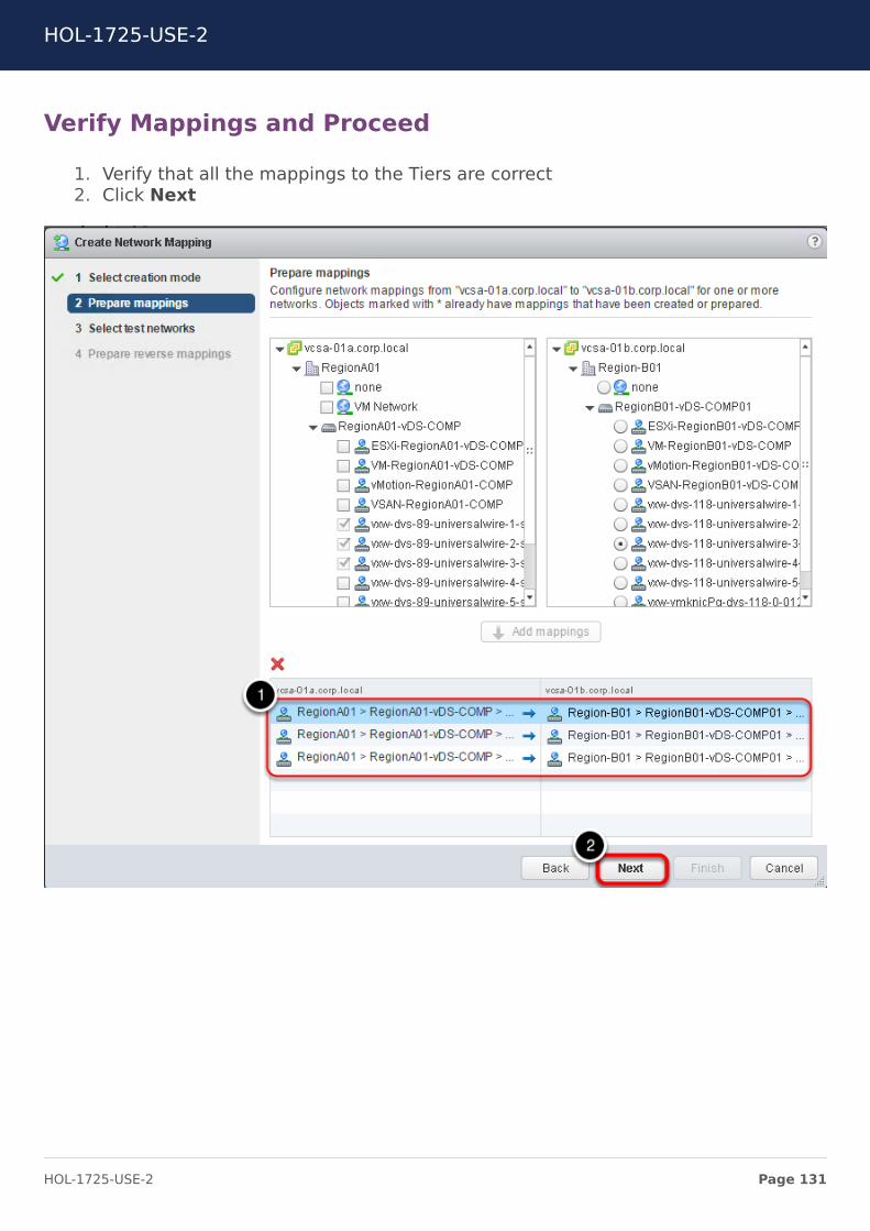
Verify Mappings and Proceed
1. Verify that all the mappings to the Tiers are correct2. Click Next
HOL-1725-USE-2
Page 131HOL-1725-USE-2

Test Networks
You are not going to make any changes to the "Select Test networks" portion of thewizard.
1. Click Next
HOL-1725-USE-2
Page 132HOL-1725-USE-2
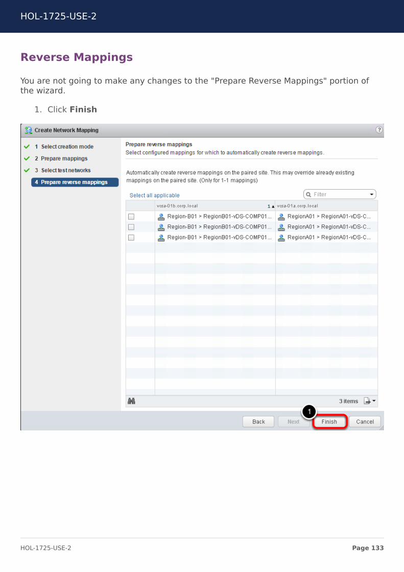
Reverse Mappings
You are not going to make any changes to the "Prepare Reverse Mappings" portion ofthe wizard.
1. Click Finish
HOL-1725-USE-2
Page 133HOL-1725-USE-2
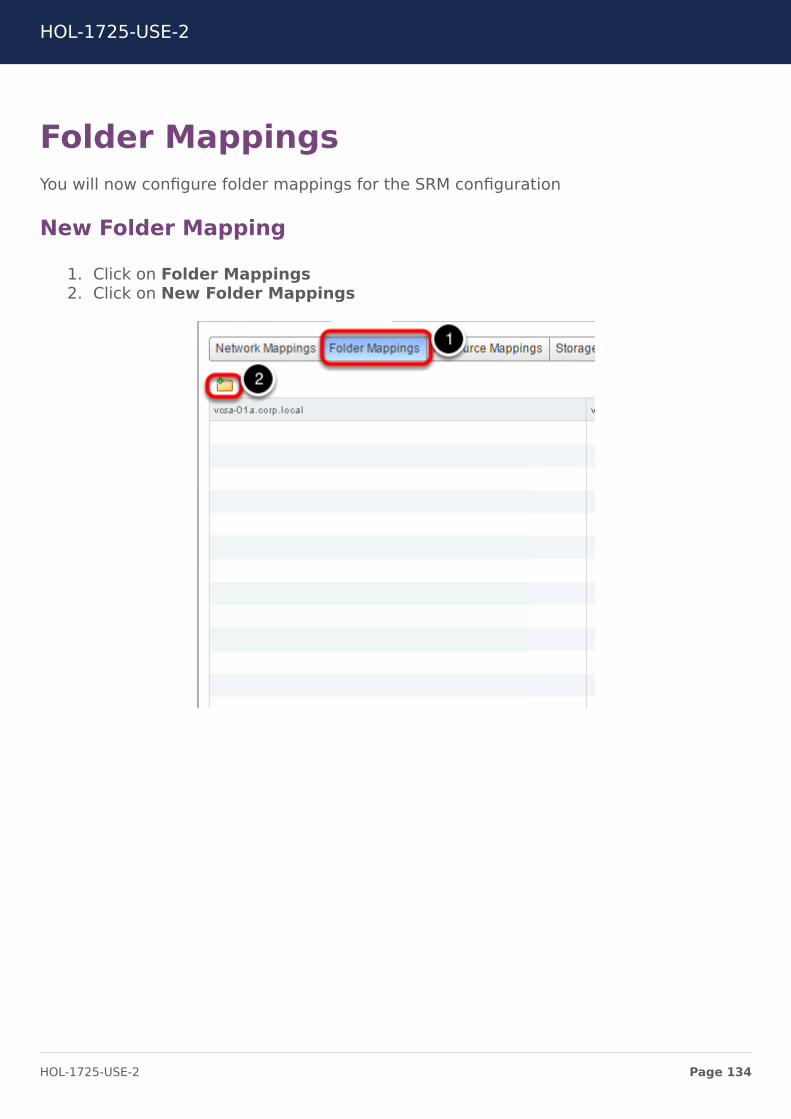
Folder MappingsYou will now configure folder mappings for the SRM configuration
New Folder Mapping
1. Click on Folder Mappings2. Click on New Folder Mappings
HOL-1725-USE-2
Page 134HOL-1725-USE-2
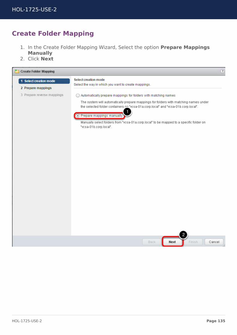
Create Folder Mapping
1. In the Create Folder Mapping Wizard, Select the option Prepare MappingsManually
2. Click Next
HOL-1725-USE-2
Page 135HOL-1725-USE-2
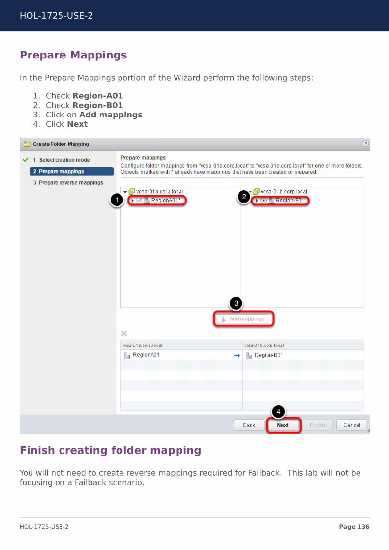
Prepare Mappings
In the Prepare Mappings portion of the Wizard perform the following steps:
1. Check Region-A012. Check Region-B013. Click on Add mappings4. Click Next
Finish creating folder mapping
You will not need to create reverse mappings required for Failback. This lab will not befocusing on a Failback scenario.
HOL-1725-USE-2
Page 136HOL-1725-USE-2
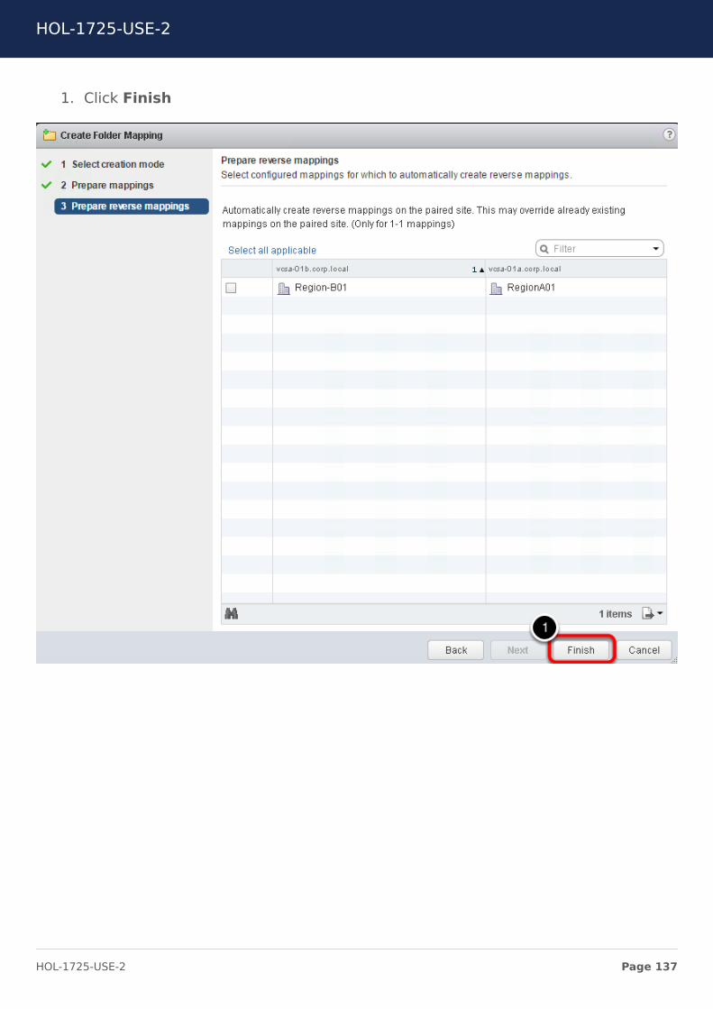
1. Click Finish
HOL-1725-USE-2
Page 137HOL-1725-USE-2
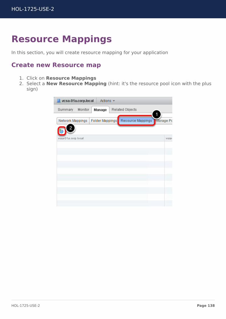
Resource MappingsIn this section, you will create resource mapping for your application
Create new Resource map
1. Click on Resource Mappings2. Select a New Resource Mapping (hint: it's the resource pool icon with the plus
sign)
HOL-1725-USE-2
Page 138HOL-1725-USE-2
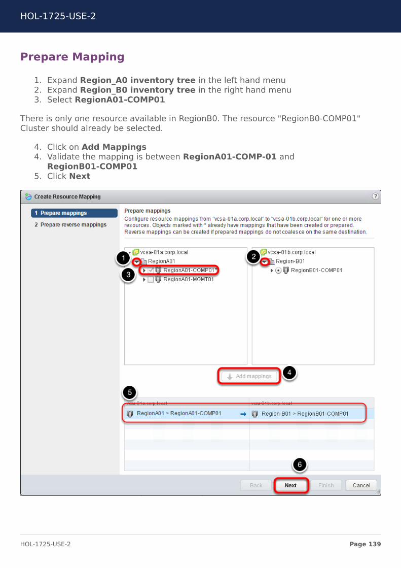
Prepare Mapping
1. Expand Region_A0 inventory tree in the left hand menu2. Expand Region_B0 inventory tree in the right hand menu3. Select RegionA01-COMP01
There is only one resource available in RegionB0. The resource "RegionB0-COMP01"Cluster should already be selected.
4. Click on Add Mappings4. Validate the mapping is between RegionA01-COMP-01 and
RegionB01-COMP015. Click Next
HOL-1725-USE-2
Page 139HOL-1725-USE-2
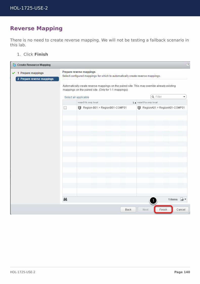
Reverse Mapping
There is no need to create reverse mapping. We will not be testing a failback scenario inthis lab.
1. Click Finish
HOL-1725-USE-2
Page 140HOL-1725-USE-2
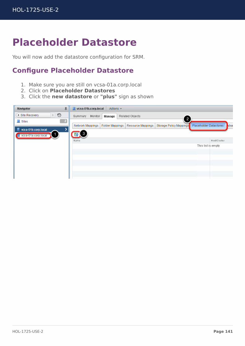
Placeholder DatastoreYou will now add the datastore configuration for SRM.
Configure Placeholder Datastore
1. Make sure you are still on vcsa-01a.corp.local2. Click on Placeholder Datastores3. Click the new datastore or "plus" sign as shown
HOL-1725-USE-2
Page 141HOL-1725-USE-2
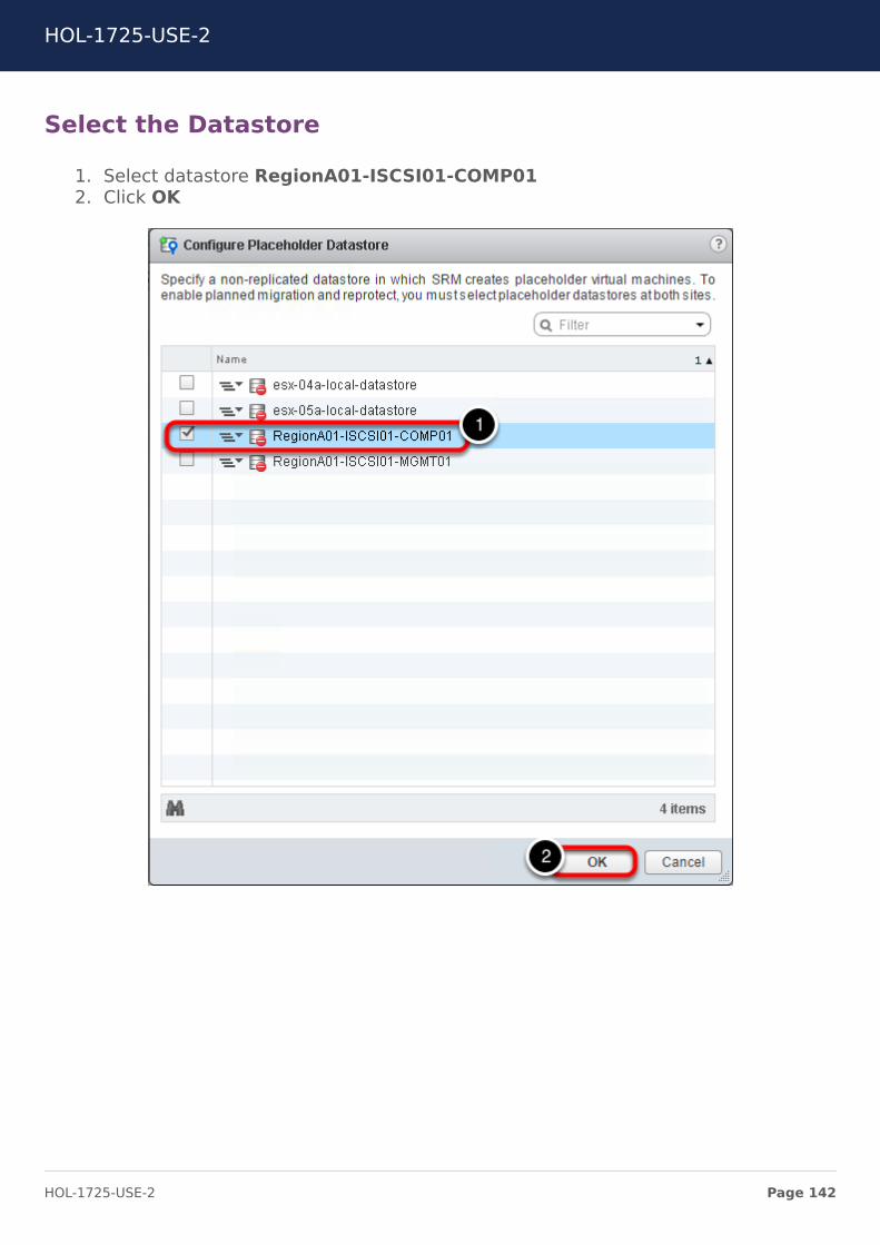
Select the Datastore
1. Select datastore RegionA01-ISCSI01-COMP012. Click OK
HOL-1725-USE-2
Page 142HOL-1725-USE-2
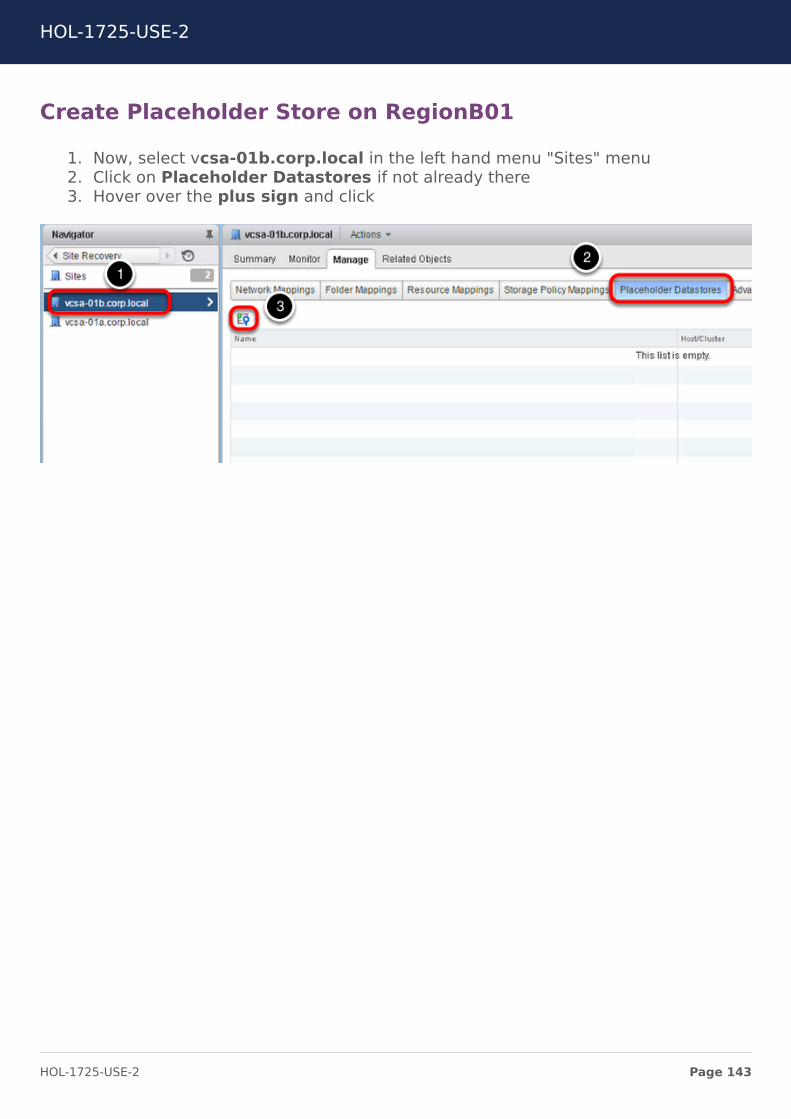
Create Placeholder Store on RegionB01
1. Now, select vcsa-01b.corp.local in the left hand menu "Sites" menu2. Click on Placeholder Datastores if not already there3. Hover over the plus sign and click
HOL-1725-USE-2
Page 143HOL-1725-USE-2
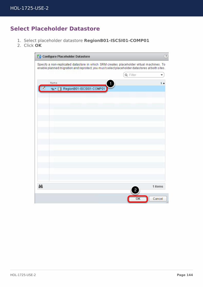
Select Placeholder Datastore
1. Select placeholder datastore RegionB01-ISCSI01-COMP012. Click OK
HOL-1725-USE-2
Page 144HOL-1725-USE-2
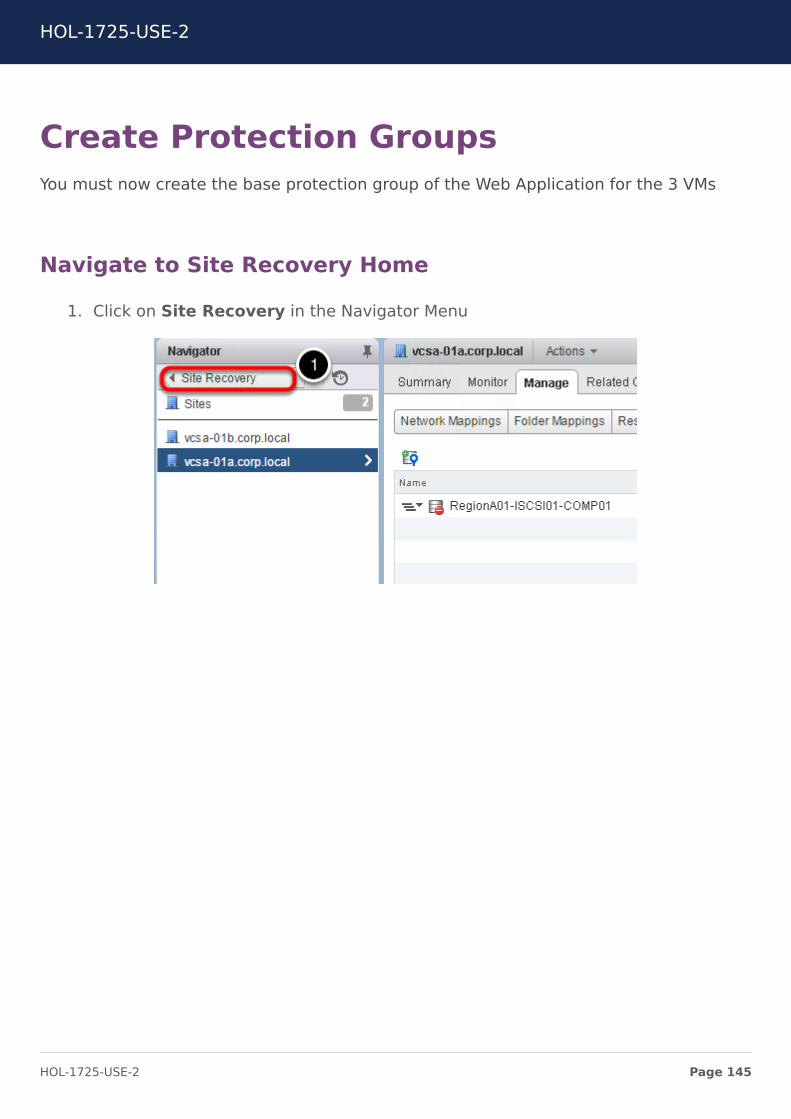
Create Protection GroupsYou must now create the base protection group of the Web Application for the 3 VMs
Navigate to Site Recovery Home
1. Click on Site Recovery in the Navigator Menu
HOL-1725-USE-2
Page 145HOL-1725-USE-2

Protection Groups
1. Select Protection Groups
HOL-1725-USE-2
Page 146HOL-1725-USE-2
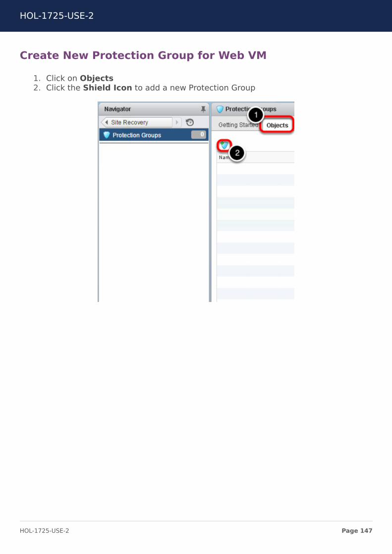
Create New Protection Group for Web VM
1. Click on Objects2. Click the Shield Icon to add a new Protection Group
HOL-1725-USE-2
Page 147HOL-1725-USE-2
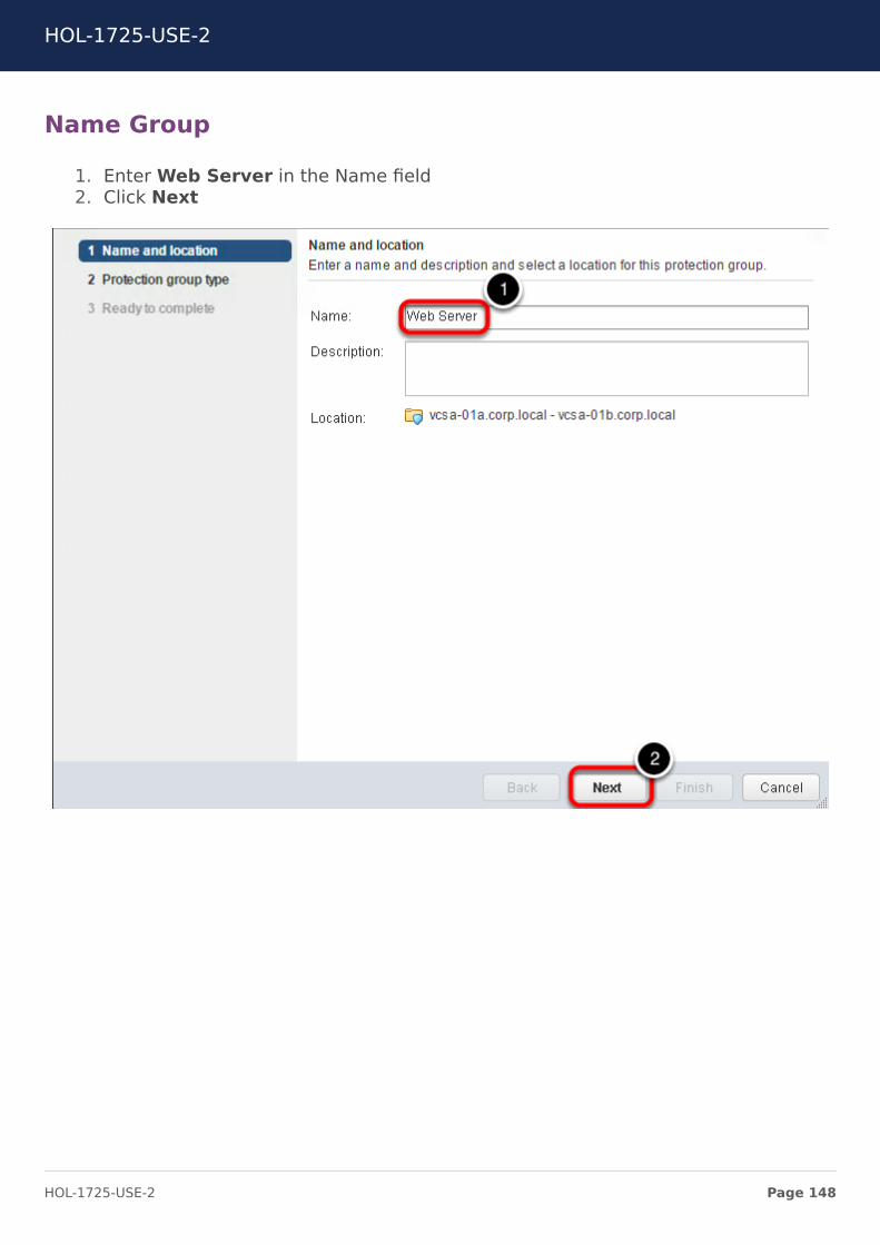
Name Group
1. Enter Web Server in the Name field2. Click Next
HOL-1725-USE-2
Page 148HOL-1725-USE-2
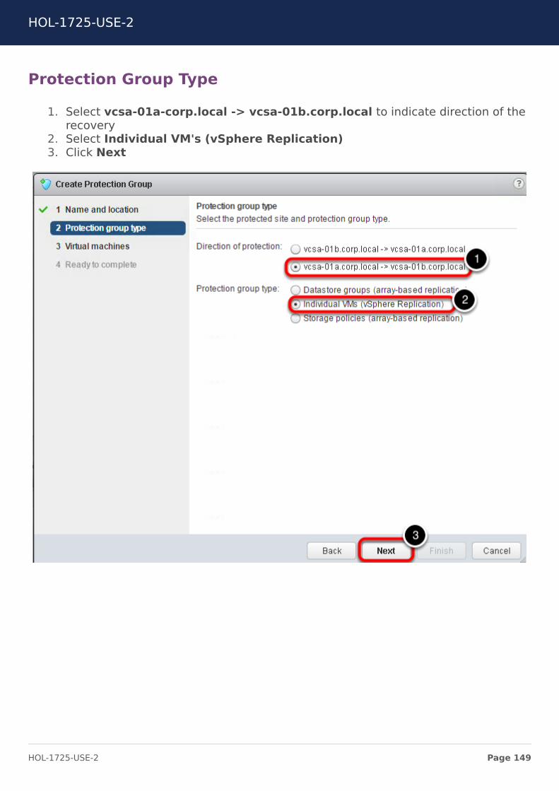
Protection Group Type
1. Select vcsa-01a-corp.local -> vcsa-01b.corp.local to indicate direction of therecovery
2. Select Individual VM's (vSphere Replication)3. Click Next
HOL-1725-USE-2
Page 149HOL-1725-USE-2
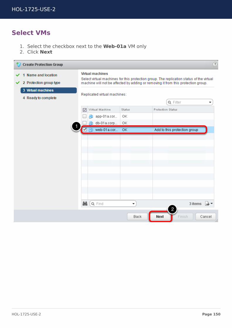
Select VMs
1. Select the checkbox next to the Web-01a VM only2. Click Next
HOL-1725-USE-2
Page 150HOL-1725-USE-2
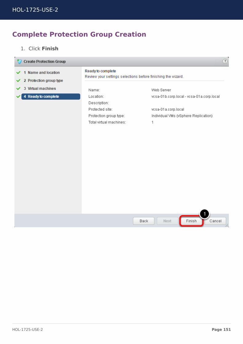
Complete Protection Group Creation
1. Click Finish
HOL-1725-USE-2
Page 151HOL-1725-USE-2
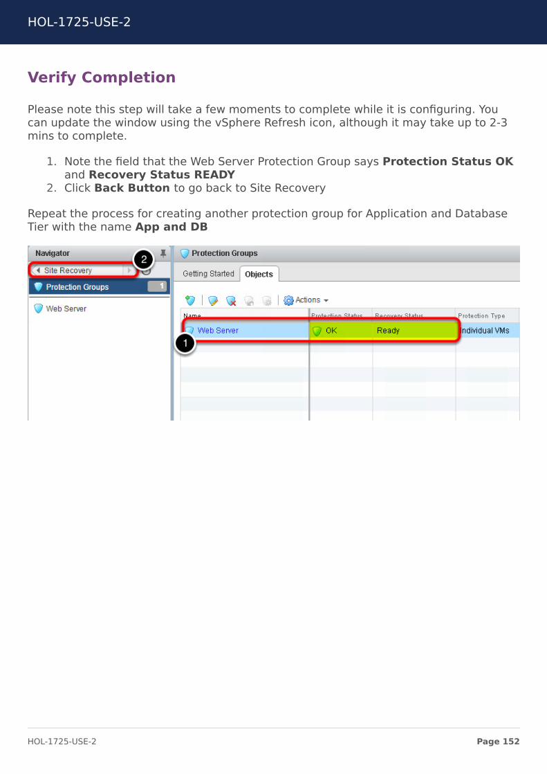
Verify Completion
Please note this step will take a few moments to complete while it is configuring. Youcan update the window using the vSphere Refresh icon, although it may take up to 2-3mins to complete.
1. Note the field that the Web Server Protection Group says Protection Status OKand Recovery Status READY
2. Click Back Button to go back to Site Recovery
Repeat the process for creating another protection group for Application and DatabaseTier with the name App and DB
HOL-1725-USE-2
Page 152HOL-1725-USE-2
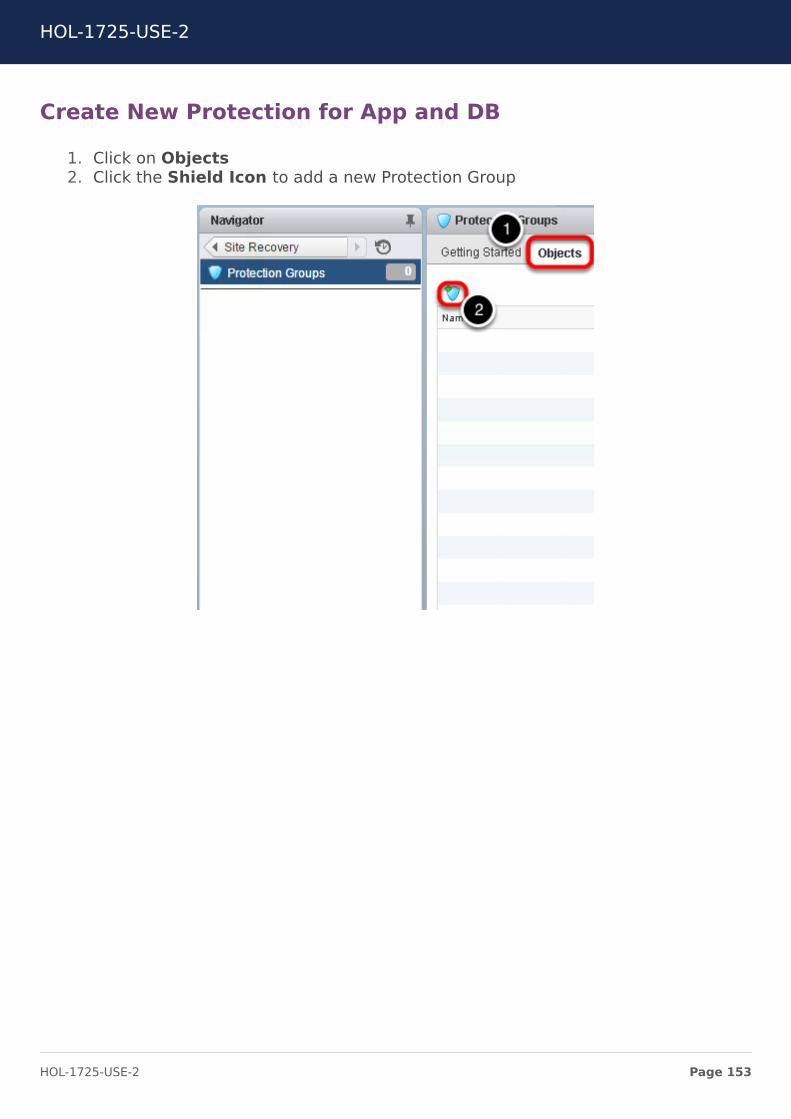
Create New Protection for App and DB
1. Click on Objects2. Click the Shield Icon to add a new Protection Group
HOL-1725-USE-2
Page 153HOL-1725-USE-2
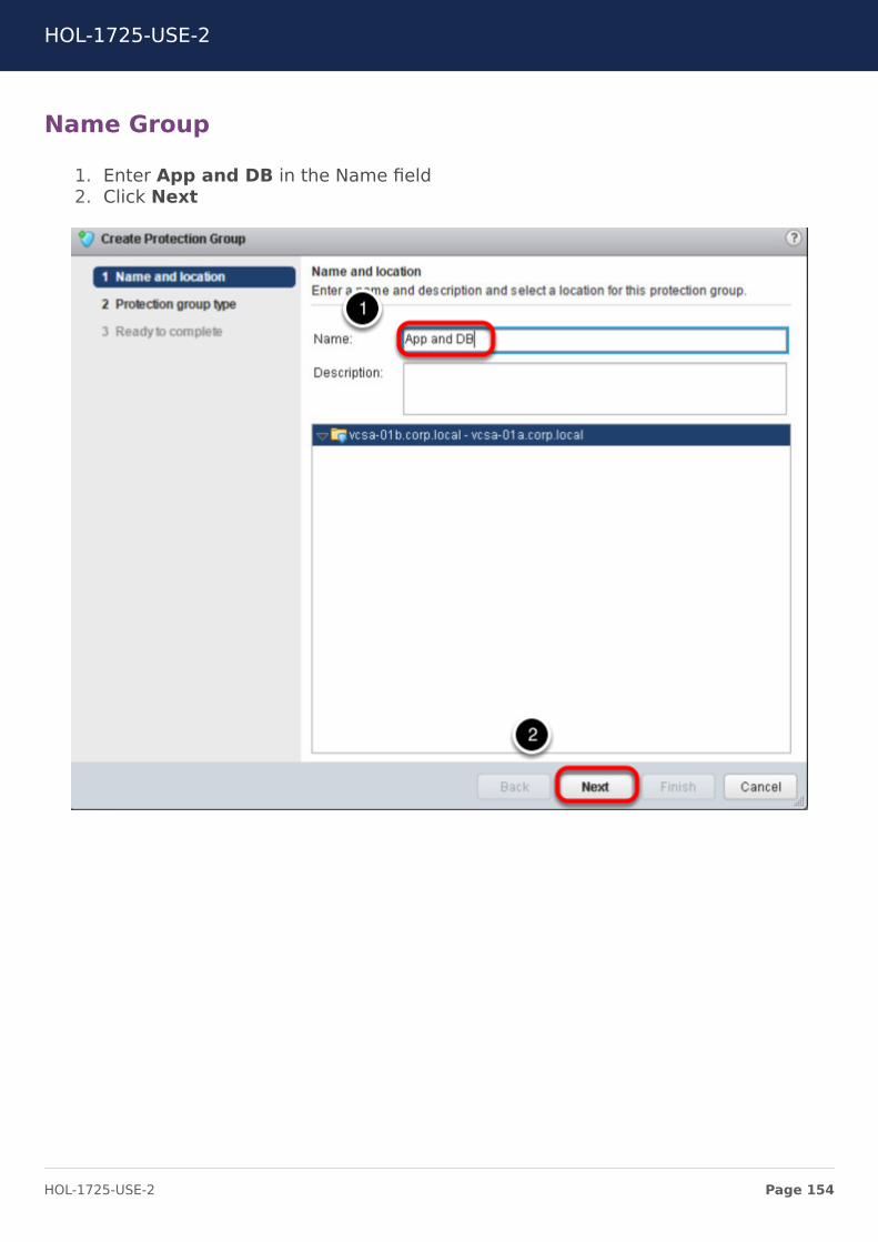
Name Group
1. Enter App and DB in the Name field2. Click Next
HOL-1725-USE-2
Page 154HOL-1725-USE-2
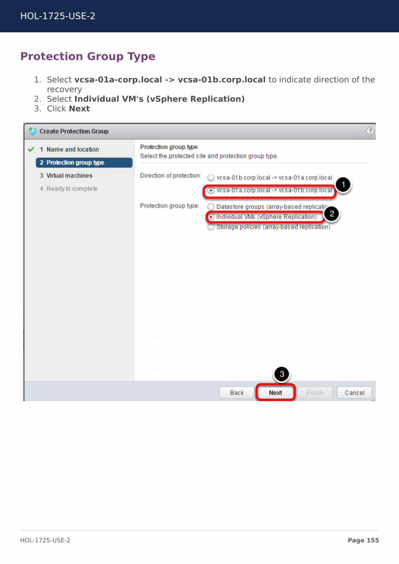
Protection Group Type
1. Select vcsa-01a-corp.local -> vcsa-01b.corp.local to indicate direction of therecovery
2. Select Individual VM's (vSphere Replication)3. Click Next
HOL-1725-USE-2
Page 155HOL-1725-USE-2
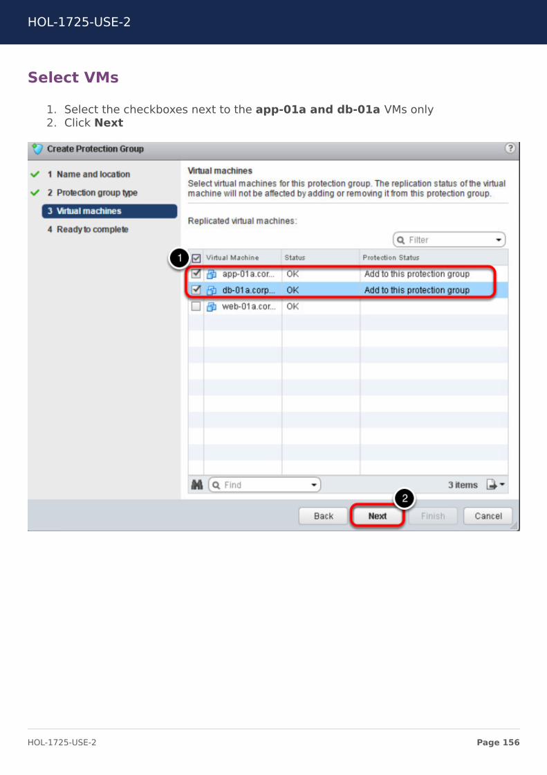
Select VMs
1. Select the checkboxes next to the app-01a and db-01a VMs only2. Click Next
HOL-1725-USE-2
Page 156HOL-1725-USE-2
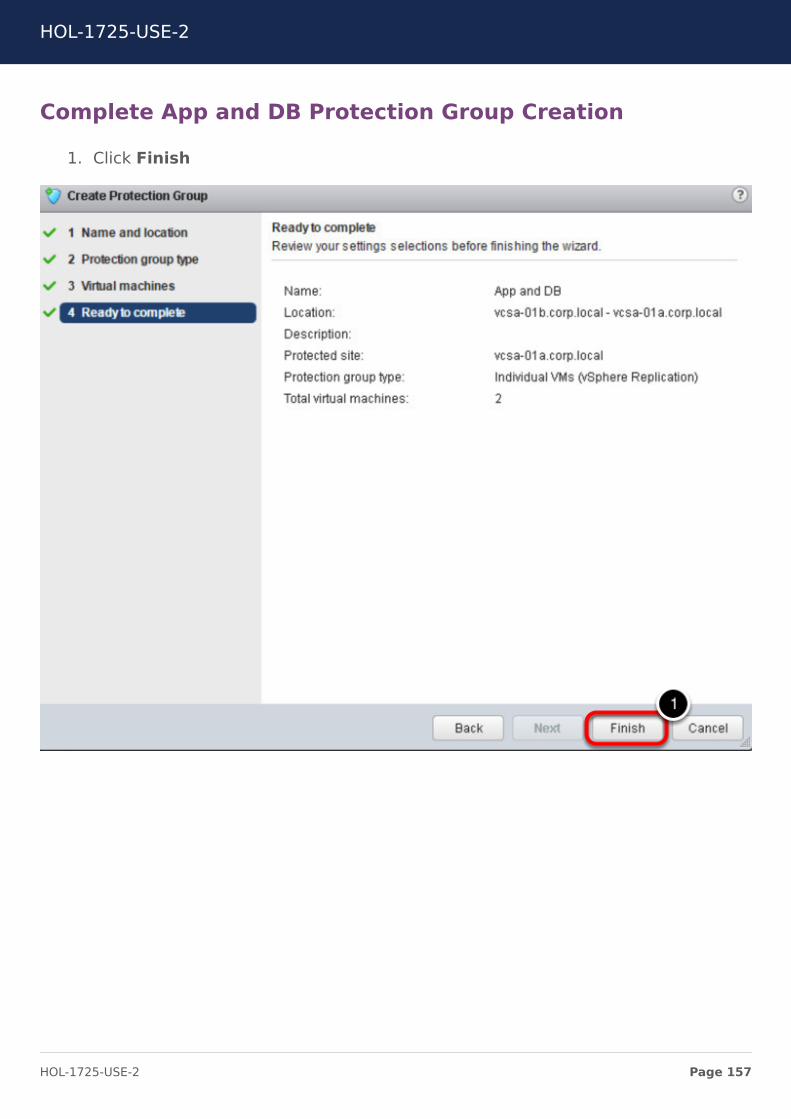
Complete App and DB Protection Group Creation
1. Click Finish
HOL-1725-USE-2
Page 157HOL-1725-USE-2
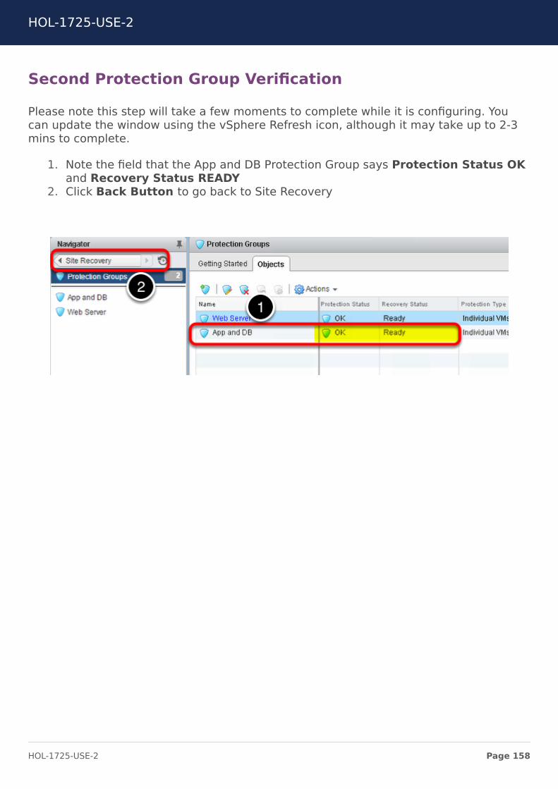
Second Protection Group Verification
Please note this step will take a few moments to complete while it is configuring. Youcan update the window using the vSphere Refresh icon, although it may take up to 2-3mins to complete.
1. Note the field that the App and DB Protection Group says Protection Status OKand Recovery Status READY
2. Click Back Button to go back to Site Recovery
HOL-1725-USE-2
Page 158HOL-1725-USE-2
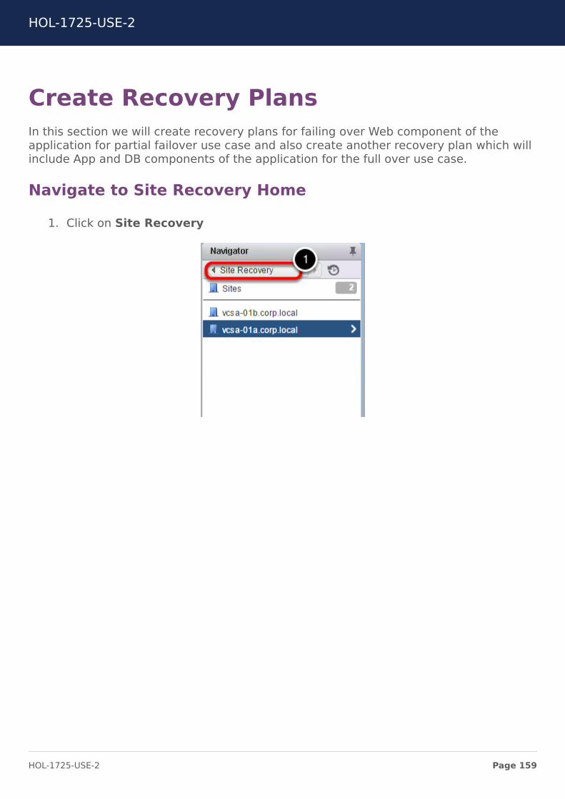
Create Recovery PlansIn this section we will create recovery plans for failing over Web component of theapplication for partial failover use case and also create another recovery plan which willinclude App and DB components of the application for the full over use case.
Navigate to Site Recovery Home
1. Click on Site Recovery
HOL-1725-USE-2
Page 159HOL-1725-USE-2
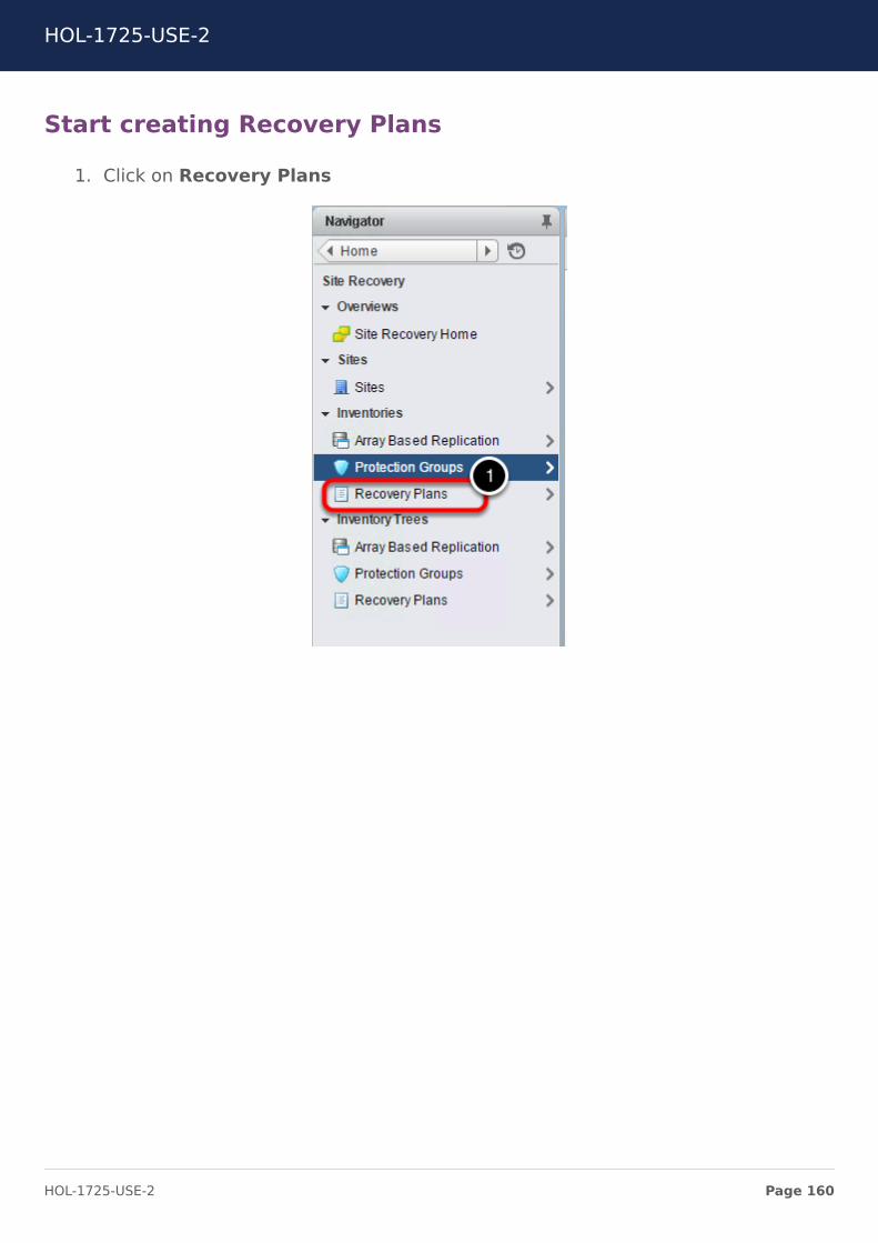
Start creating Recovery Plans
1. Click on Recovery Plans
HOL-1725-USE-2
Page 160HOL-1725-USE-2
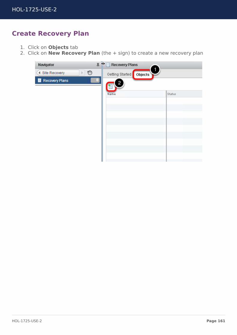
Create Recovery Plan
1. Click on Objects tab2. Click on New Recovery Plan (the + sign) to create a new recovery plan
HOL-1725-USE-2
Page 161HOL-1725-USE-2
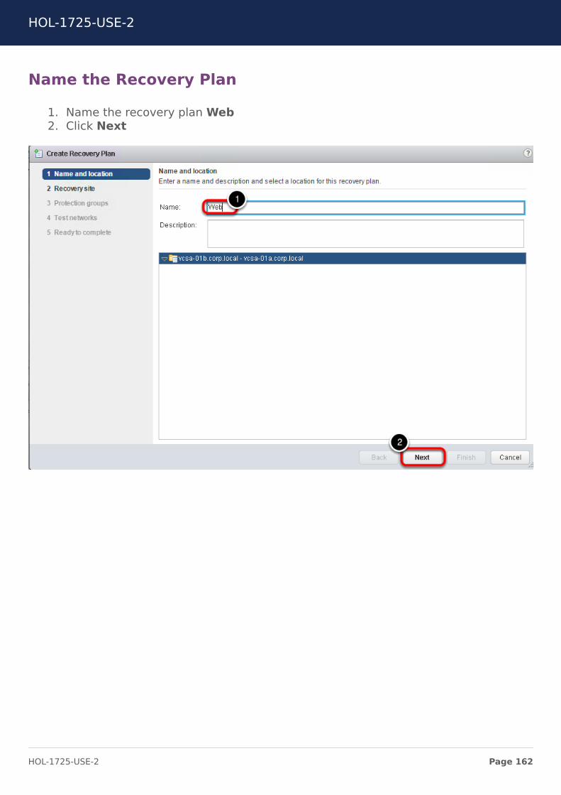
Name the Recovery Plan
1. Name the recovery plan Web2. Click Next
HOL-1725-USE-2
Page 162HOL-1725-USE-2
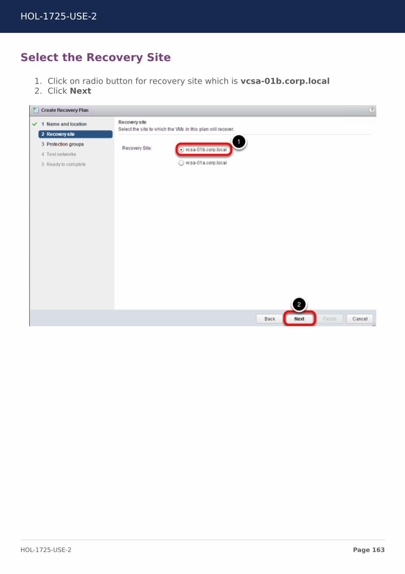
Select the Recovery Site
1. Click on radio button for recovery site which is vcsa-01b.corp.local2. Click Next
HOL-1725-USE-2
Page 163HOL-1725-USE-2
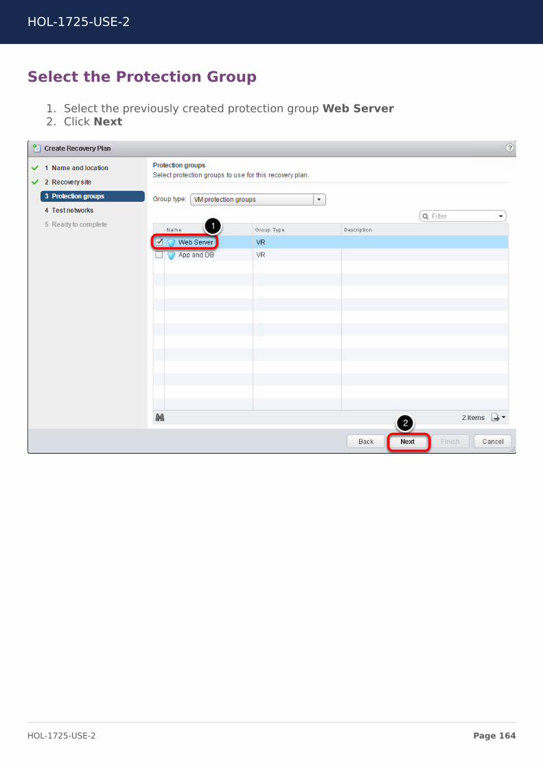
Select the Protection Group
1. Select the previously created protection group Web Server2. Click Next
HOL-1725-USE-2
Page 164HOL-1725-USE-2
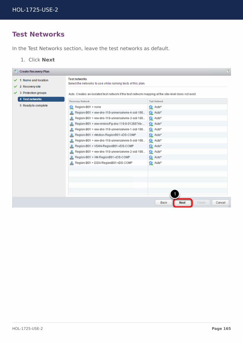
Test Networks
In the Test Networks section, leave the test networks as default.
1. Click Next
HOL-1725-USE-2
Page 165HOL-1725-USE-2
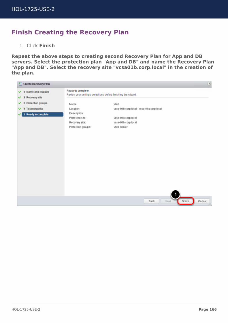
Finish Creating the Recovery Plan
1. Click Finish
Repeat the above steps to creating second Recovery Plan for App and DBservers. Select the protection plan "App and DB" and name the Recovery Plan"App and DB". Select the recovery site "vcsa01b.corp.local" in the creation ofthe plan.
HOL-1725-USE-2
Page 166HOL-1725-USE-2
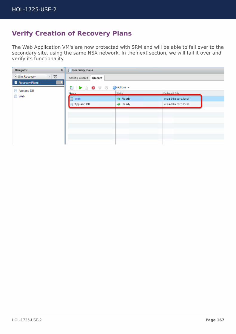
Verify Creation of Recovery Plans
The Web Application VM's are now protected with SRM and will be able to fail over to thesecondary site, using the same NSX network. In the next section, we will fail it over andverify its functionality.
HOL-1725-USE-2
Page 167HOL-1725-USE-2
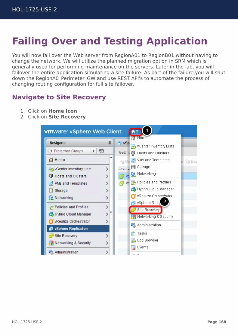
Failing Over and Testing ApplicationYou will now fail over the Web server from RegionA01 to RegionB01 without having tochange the network. We will utilize the planned migration option in SRM which isgenerally used for performing maintenance on the servers. Later in the lab, you willfailover the entire application simulating a site failure. As part of the failure,you will shutdown the RegionA0_Perimeter_GW and use REST API's to automate the process ofchanging routing configuration for full site failover.
Navigate to Site Recovery
1. Click on Home Icon2. Click on Site Recovery
HOL-1725-USE-2
Page 168HOL-1725-USE-2
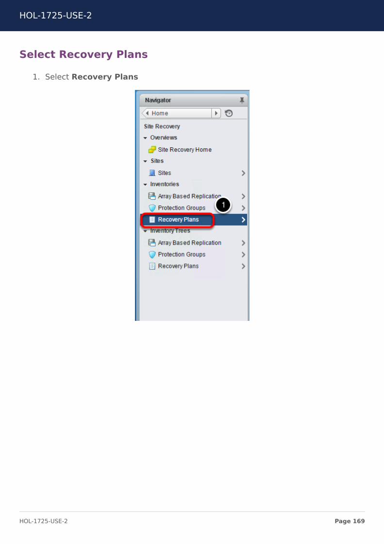
Select Recovery Plans
1. Select Recovery Plans
HOL-1725-USE-2
Page 169HOL-1725-USE-2

Select Web
1. Select Web
HOL-1725-USE-2
Page 170HOL-1725-USE-2
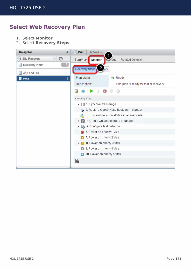
Select Web Recovery Plan
1. Select Monitor2. Select Recovery Steps
HOL-1725-USE-2
Page 171HOL-1725-USE-2
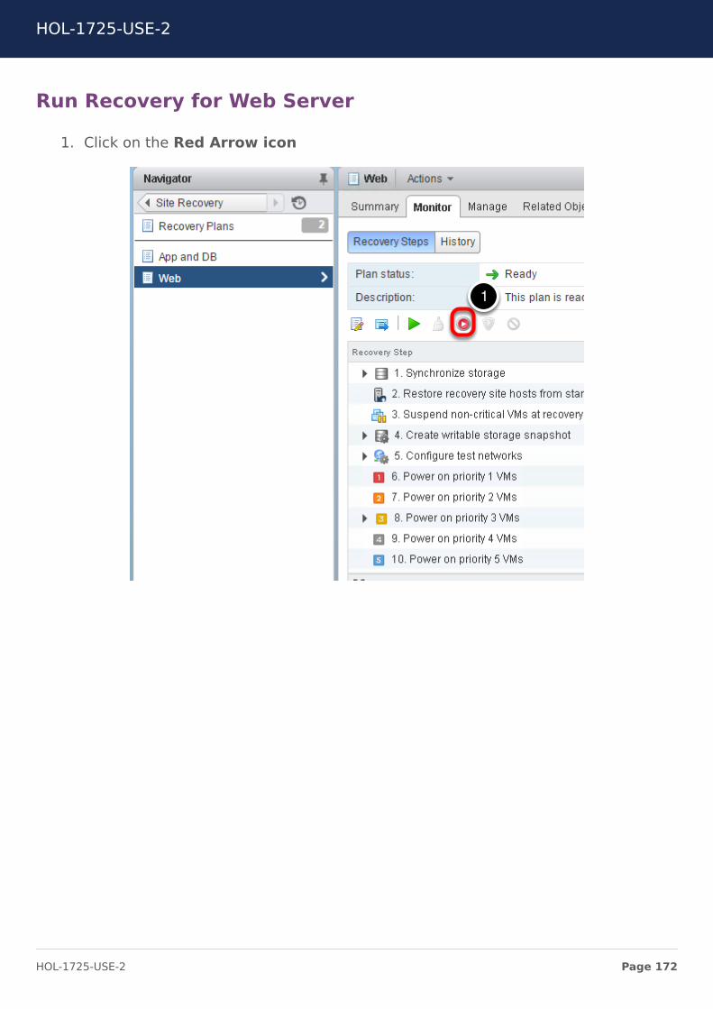
Run Recovery for Web Server
1. Click on the Red Arrow icon
HOL-1725-USE-2
Page 172HOL-1725-USE-2
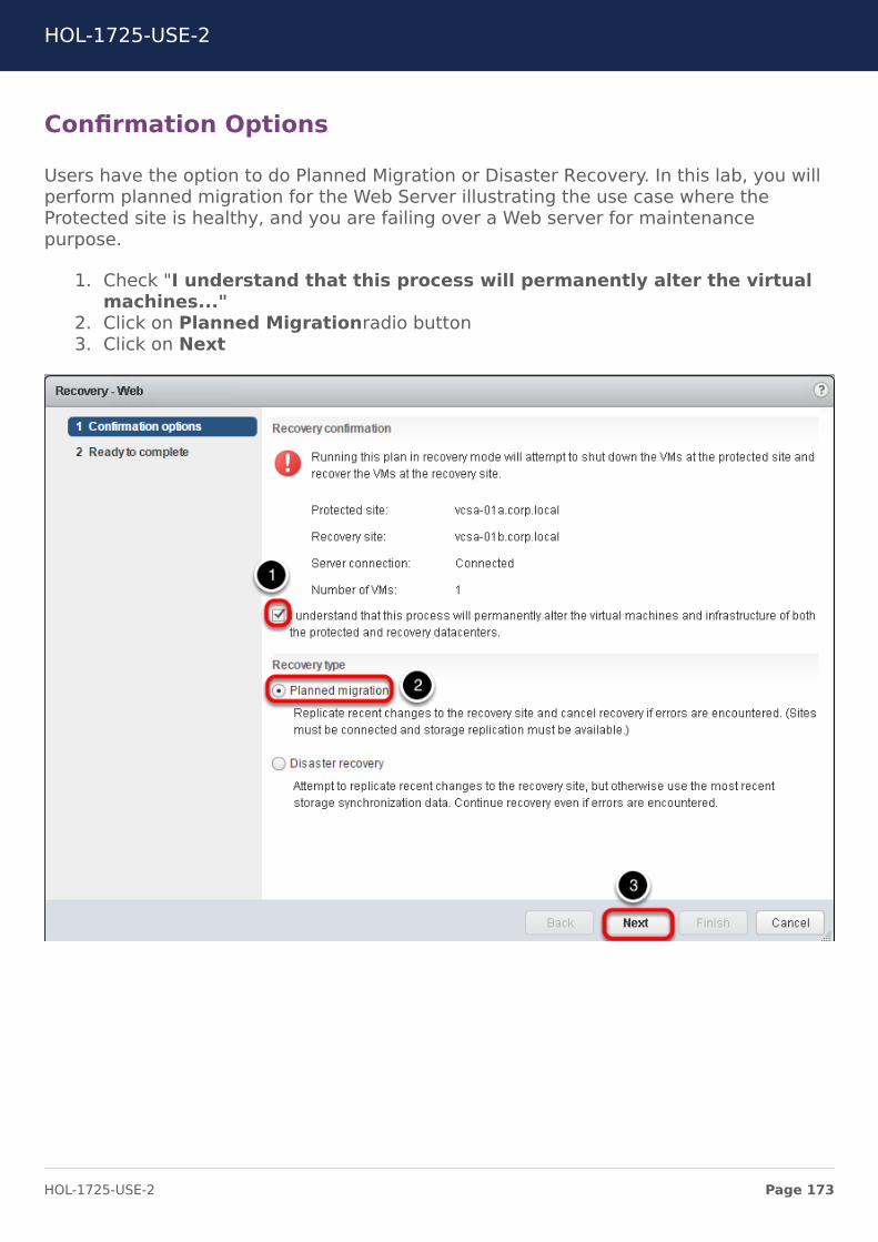
Confirmation Options
Users have the option to do Planned Migration or Disaster Recovery. In this lab, you willperform planned migration for the Web Server illustrating the use case where theProtected site is healthy, and you are failing over a Web server for maintenancepurpose.
1. Check "I understand that this process will permanently alter the virtualmachines..."
2. Click on Planned Migrationradio button3. Click on Next
HOL-1725-USE-2
Page 173HOL-1725-USE-2
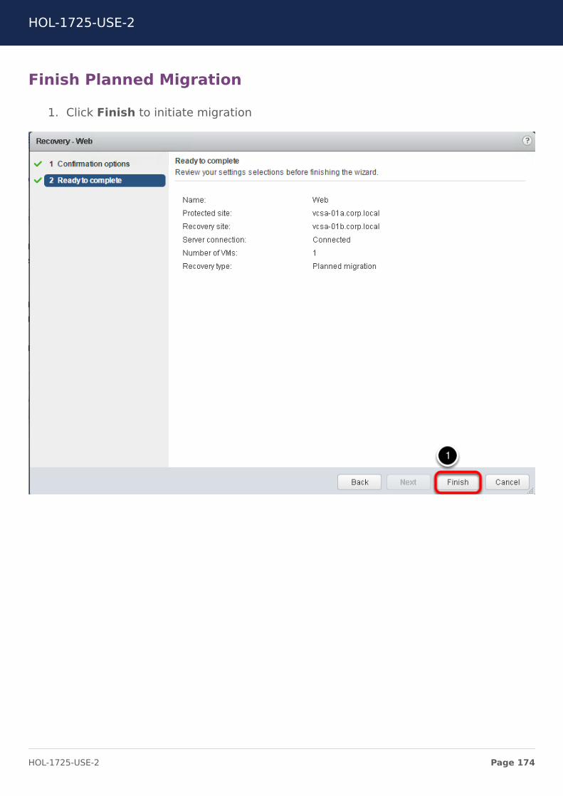
Finish Planned Migration
1. Click Finish to initiate migration
HOL-1725-USE-2
Page 174HOL-1725-USE-2
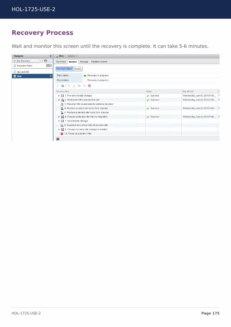
Recovery Process
Wait and monitor this screen until the recovery is complete. It can take 5-6 minutes.
HOL-1725-USE-2
Page 175HOL-1725-USE-2
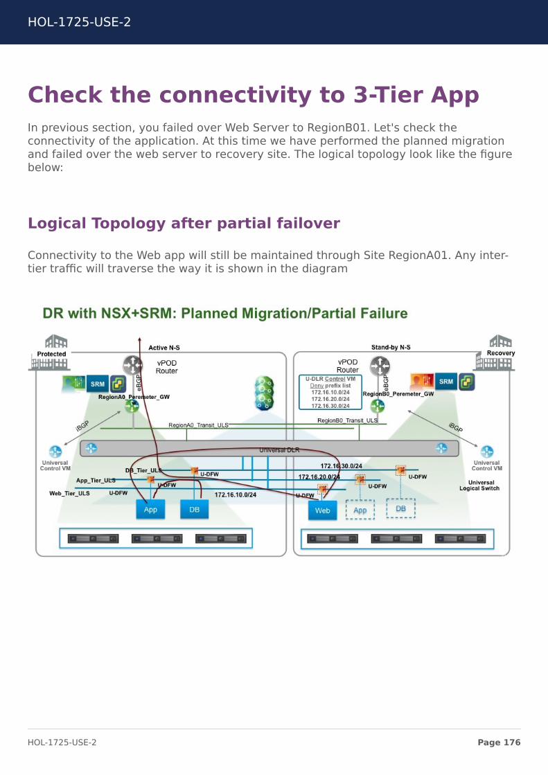
Check the connectivity to 3-Tier AppIn previous section, you failed over Web Server to RegionB01. Let's check theconnectivity of the application. At this time we have performed the planned migrationand failed over the web server to recovery site. The logical topology look like the figurebelow:
Logical Topology after partial failover
Connectivity to the Web app will still be maintained through Site RegionA01. Any inter-tier traffic will traverse the way it is shown in the diagram
HOL-1725-USE-2
Page 176HOL-1725-USE-2
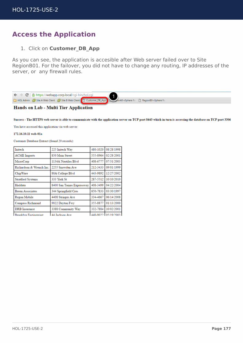
Access the Application
1. Click on Customer_DB_App
As you can see, the application is accesible after Web server failed over to SiteRegionB01. For the failover, you did not have to change any routing, IP addresses of theserver, or any firewall rules.
HOL-1725-USE-2
Page 177HOL-1725-USE-2
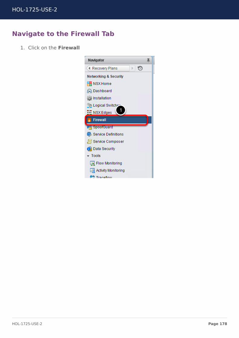
Navigate to the Firewall Tab
1. Click on the Firewall
HOL-1725-USE-2
Page 178HOL-1725-USE-2

Navigate to the Primary NSX manager and expand theThree Tier App section
1. Click on NSX Manager drop down2. Select 192.168.110.15 (Role Primary)3. Click and expand the Three Tier App section
HOL-1725-USE-2
Page 179HOL-1725-USE-2
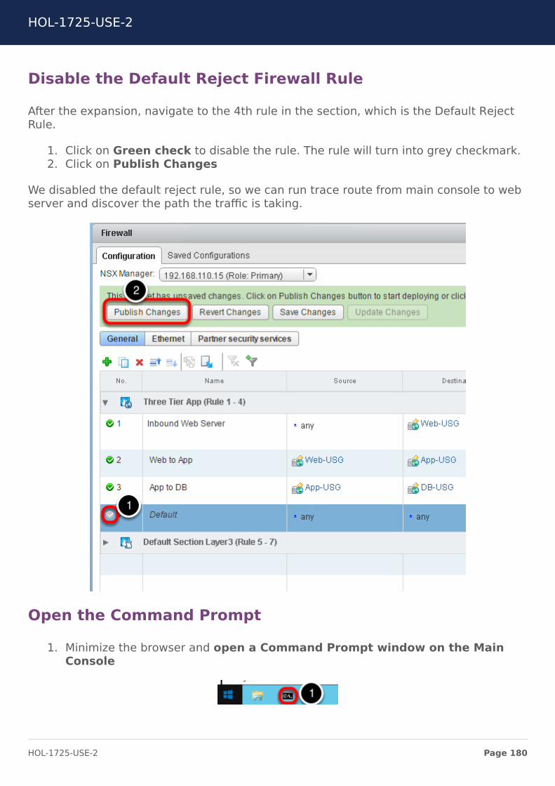
Disable the Default Reject Firewall Rule
After the expansion, navigate to the 4th rule in the section, which is the Default RejectRule.
1. Click on Green check to disable the rule. The rule will turn into grey checkmark.2. Click on Publish Changes
We disabled the default reject rule, so we can run trace route from main console to webserver and discover the path the traffic is taking.
Open the Command Prompt
1. Minimize the browser and open a Command Prompt window on the MainConsole
HOL-1725-USE-2
Page 180HOL-1725-USE-2
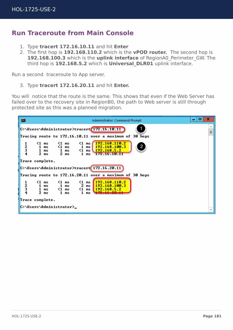
Run Traceroute from Main Console
1. Type tracert 172.16.10.11 and hit Enter2. The first hop is 192.168.110.2 which is the vPOD router. The second hop is
192.168.100.3 which is the uplink interface of RegionA0_Perimeter_GW. Thethird hop is 192.168.5.2 which is Universal_DLR01 uplink interface.
Run a second traceroute to App server.
3. Type tracert 172.16.20.11 and hit Enter.
You will notice that the route is the same. This shows that even if the Web Server hasfailed over to the recovery site in RegionB0, the path to Web server is still throughprotected site as this was a planned migration.
HOL-1725-USE-2
Page 181HOL-1725-USE-2

Navigate to Hosts and Clusters
1. Click on Home icon2. Click on Hosts and Cluster
HOL-1725-USE-2
Page 182HOL-1725-USE-2
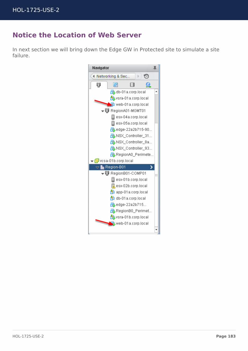
Notice the Location of Web Server
In next section we will bring down the Edge GW in Protected site to simulate a sitefailure.
HOL-1725-USE-2
Page 183HOL-1725-USE-2
Bring down the Edge GWIn this section, you will shut down the RegionA0_Perimeter_GW to simulate failure. In areal time environment, organizations can have multiple component failure. Thosecomponents could be any one of the listed below:
1. Controller Cluster Failure2. Edge GW Failure3. Physical Router Failure4. WAN Link Failure5. NSX Manager Failure6. DCI Failure
Within the scope of this lab we are not targeting all the failures. There is an excellentwhite paper that you can refer to which covers some of the failures in the environment.The white paper is available at the URL below:
https://communities.vmware.com/docs/DOC-31692
HOL-1725-USE-2
Page 184HOL-1725-USE-2
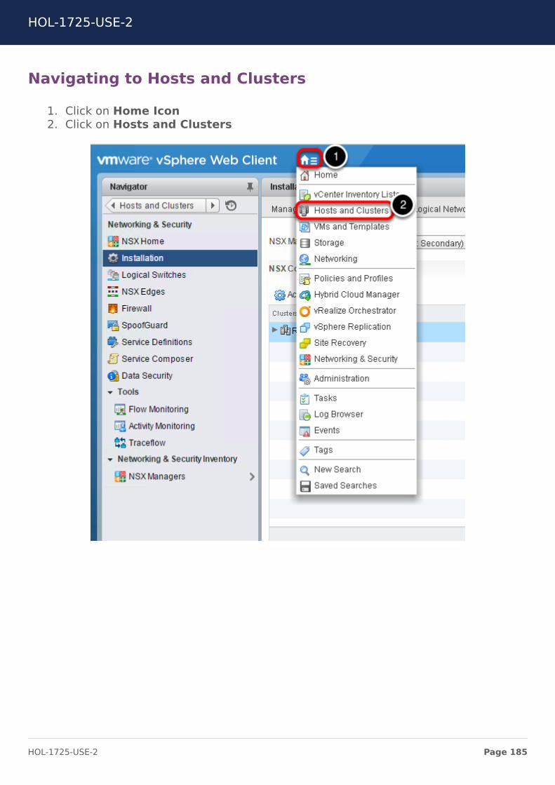
Navigating to Hosts and Clusters
1. Click on Home Icon2. Click on Hosts and Clusters
HOL-1725-USE-2
Page 185HOL-1725-USE-2
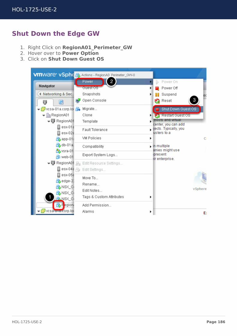
Shut Down the Edge GW
1. Right Click on RegionA01_Perimeter_GW2. Hover over to Power Option3. Click on Shut Down Guest OS
HOL-1725-USE-2
Page 186HOL-1725-USE-2
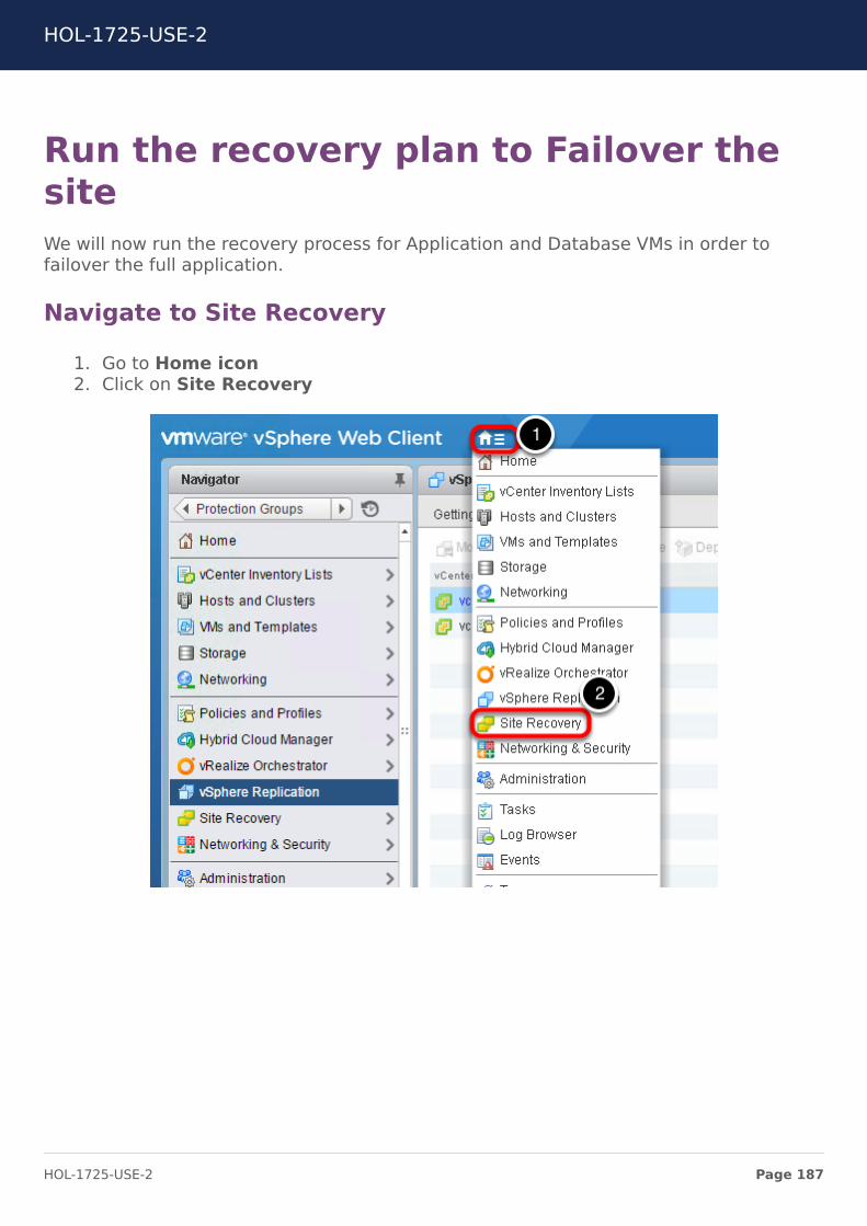
Run the recovery plan to Failover thesiteWe will now run the recovery process for Application and Database VMs in order tofailover the full application.
Navigate to Site Recovery
1. Go to Home icon2. Click on Site Recovery
HOL-1725-USE-2
Page 187HOL-1725-USE-2
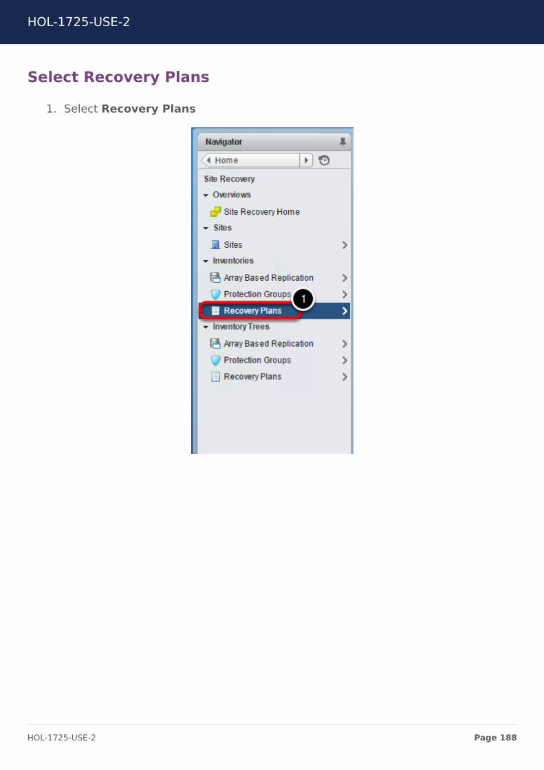
Select Recovery Plans
1. Select Recovery Plans
HOL-1725-USE-2
Page 188HOL-1725-USE-2
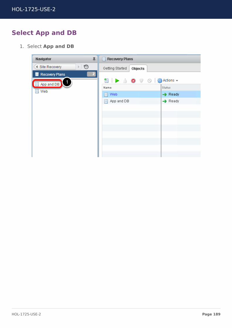
Select App and DB
1. Select App and DB
HOL-1725-USE-2
Page 189HOL-1725-USE-2
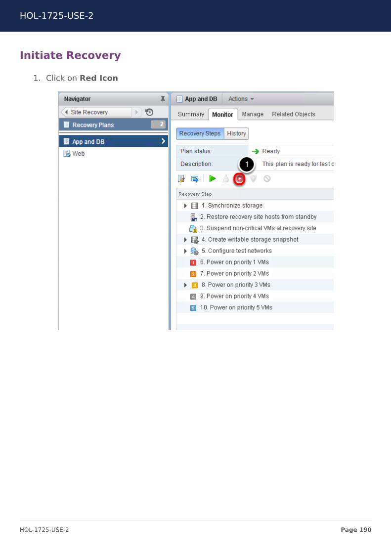
Initiate Recovery
1. Click on Red Icon
HOL-1725-USE-2
Page 190HOL-1725-USE-2
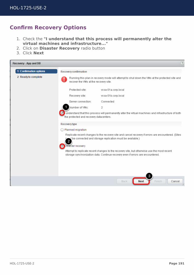
Confirm Recovery Options
1. Check the "I understand that this process will permanently alter thevirtual machines and infrastructure..."
2. Click on Disaster Recovery radio button3. Click Next
HOL-1725-USE-2
Page 191HOL-1725-USE-2
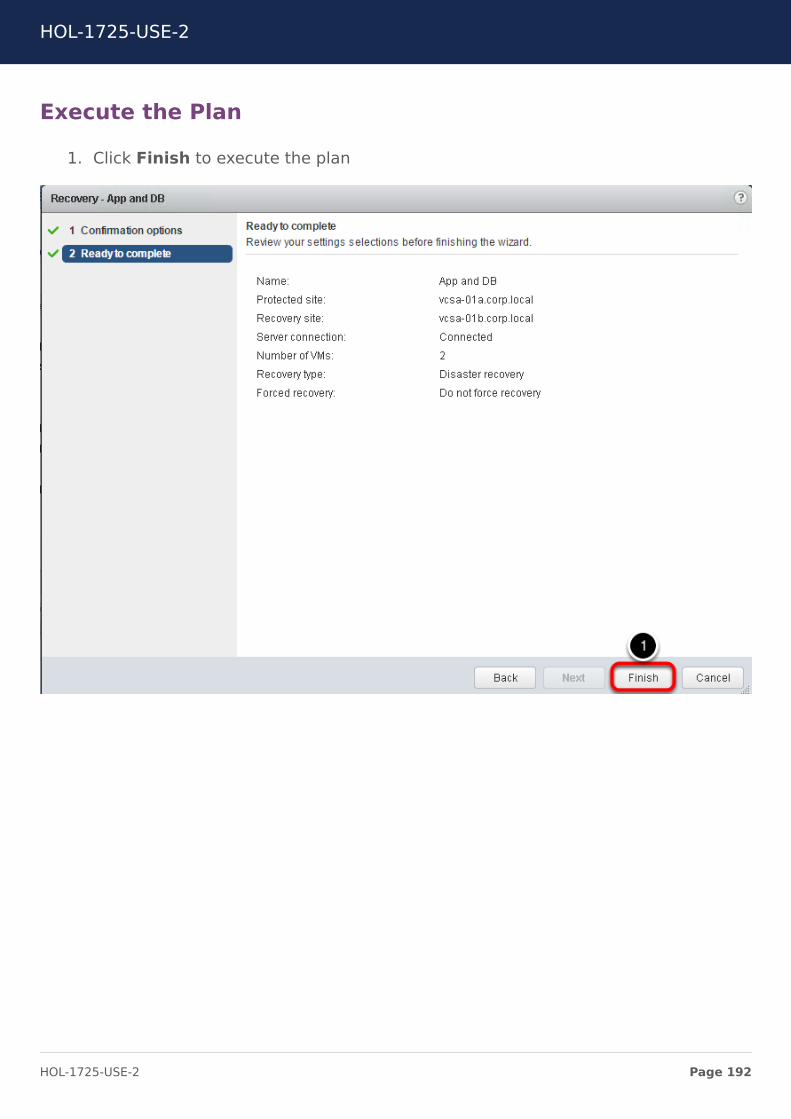
Execute the Plan
1. Click Finish to execute the plan
HOL-1725-USE-2
Page 192HOL-1725-USE-2
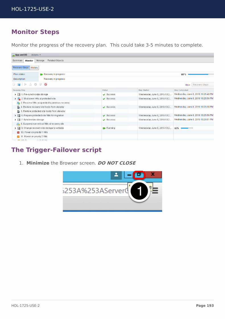
Monitor Steps
Monitor the progress of the recovery plan. This could take 3-5 minutes to complete.
The Trigger-Failover script
1. Minimize the Browser screen. DO NOT CLOSE
HOL-1725-USE-2
Page 193HOL-1725-USE-2
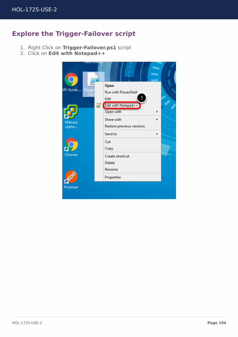
Explore the Trigger-Failover script
1. Right Click on Trigger-Failover.ps1 script2. Click on Edit with Notepad++
HOL-1725-USE-2
Page 194HOL-1725-USE-2
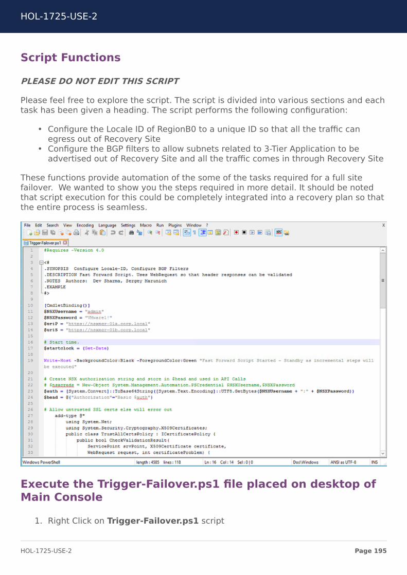
Script Functions
PLEASE DO NOT EDIT THIS SCRIPT
Please feel free to explore the script. The script is divided into various sections and eachtask has been given a heading. The script performs the following configuration:
• Configure the Locale ID of RegionB0 to a unique ID so that all the traffic canegress out of Recovery Site
• Configure the BGP filters to allow subnets related to 3-Tier Application to beadvertised out of Recovery Site and all the traffic comes in through Recovery Site
These functions provide automation of the some of the tasks required for a full sitefailover. We wanted to show you the steps required in more detail. It should be notedthat script execution for this could be completely integrated into a recovery plan so thatthe entire process is seamless.
Execute the Trigger-Failover.ps1 file placed on desktop ofMain Console
1. Right Click on Trigger-Failover.ps1 script
HOL-1725-USE-2
Page 195HOL-1725-USE-2
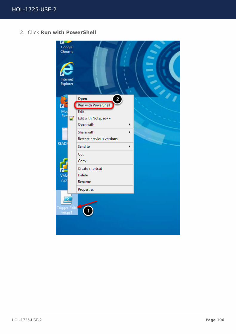
2. Click Run with PowerShell
HOL-1725-USE-2
Page 196HOL-1725-USE-2
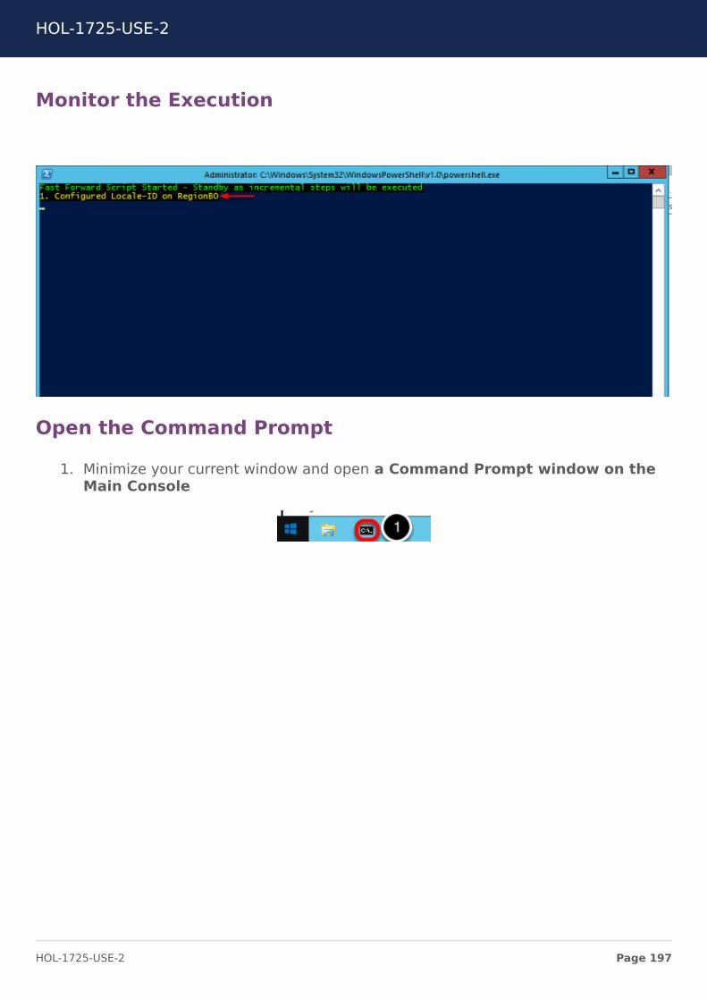
Monitor the Execution
Open the Command Prompt
1. Minimize your current window and open a Command Prompt window on theMain Console
HOL-1725-USE-2
Page 197HOL-1725-USE-2
Run Traceroute from Main Console
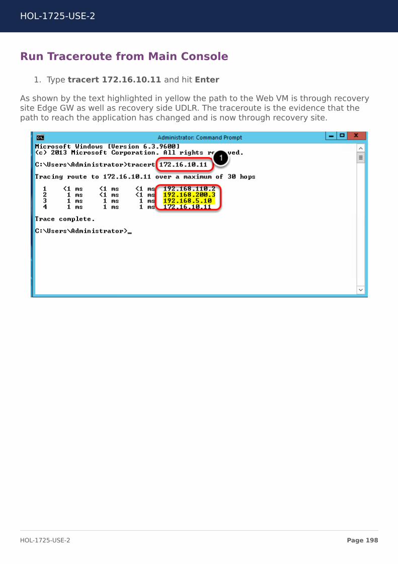
1. Type tracert 172.16.10.11 and hit Enter
As shown by the text highlighted in yellow the path to the Web VM is through recoverysite Edge GW as well as recovery side UDLR. The traceroute is the evidence that thepath to reach the application has changed and is now through recovery site.
HOL-1725-USE-2
Page 198HOL-1725-USE-2
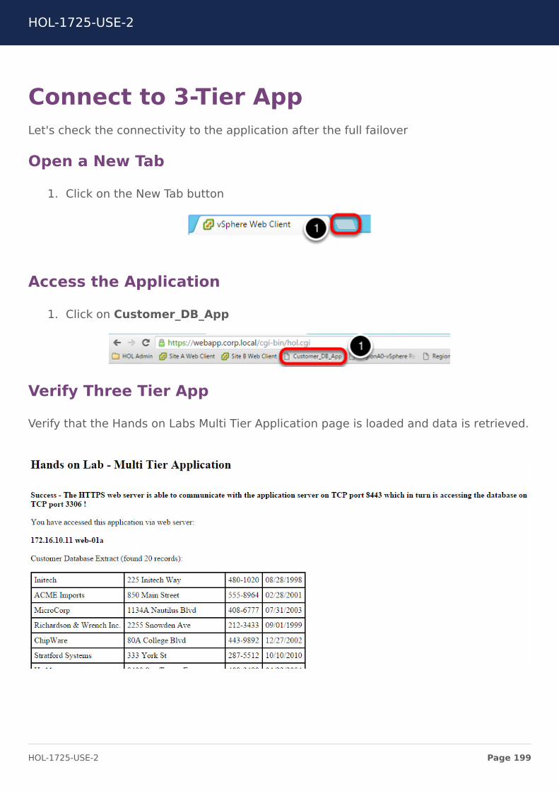
Connect to 3-Tier AppLet's check the connectivity to the application after the full failover
Open a New Tab
1. Click on the New Tab button
Access the Application
1. Click on Customer_DB_App
Verify Three Tier App
Verify that the Hands on Labs Multi Tier Application page is loaded and data is retrieved.
HOL-1725-USE-2
Page 199HOL-1725-USE-2
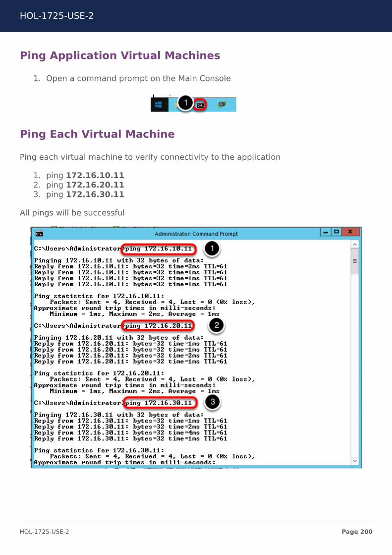
Ping Application Virtual Machines
1. Open a command prompt on the Main Console
Ping Each Virtual Machine
Ping each virtual machine to verify connectivity to the application
1. ping 172.16.10.112. ping 172.16.20.113. ping 172.16.30.11
All pings will be successful
HOL-1725-USE-2
Page 200HOL-1725-USE-2
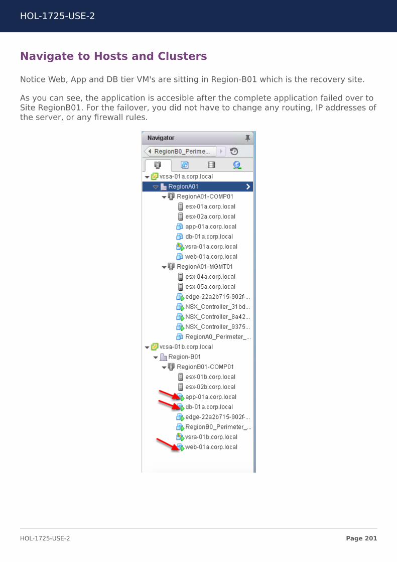
Navigate to Hosts and Clusters
Notice Web, App and DB tier VM's are sitting in Region-B01 which is the recovery site.
As you can see, the application is accesible after the complete application failed over toSite RegionB01. For the failover, you did not have to change any routing, IP addresses ofthe server, or any firewall rules.
HOL-1725-USE-2
Page 201HOL-1725-USE-2
Module 2 ConclusionThis module walked you through the configuration of SRM including creation ofprotection groups and recovery plans used as recovery run book for failing overapplication from protected site to recovery site.
While we did cover reverse mappings, they are also a very important topic. Reversemappings are necessary to failback from Recovery Site to Protected site once theProtected site is in a stabilized state.
NSX is a platform built from ground up for supporting automation. In this lab weleveraged scripting to initiate certain workflows which allowed us to failover the trafficfrom Protected Site to Recovery Site without manually changing routing configuration.
If you would like more info on Site Recovery Manager, please vist HOL-1705-SDC-1Data Center Migration and Disaster Recovery with Site Recovery Manager.
You've finished Module 2
Congratulations on completing Module 2 and this completes the lab.
Lab Captain:
• Module 1 - 2 Dev Sharma, Staff Systems Engineer-Canada
How to End Lab
To end the lab click on the END button.
HOL-1725-USE-2
Page 202HOL-1725-USE-2
ConclusionThank you for participating in the VMware Hands-on Labs. Be sure to visithttp://hol.vmware.com/ to continue your lab experience online.
Lab SKU: HOL-1725-USE-2
Version: 20161024-132435
HOL-1725-USE-2
Page 203HOL-1725-USE-2