lab property number(s): -...
TRANSCRIPT
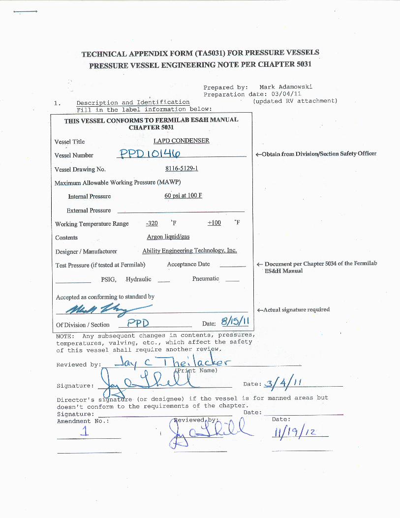
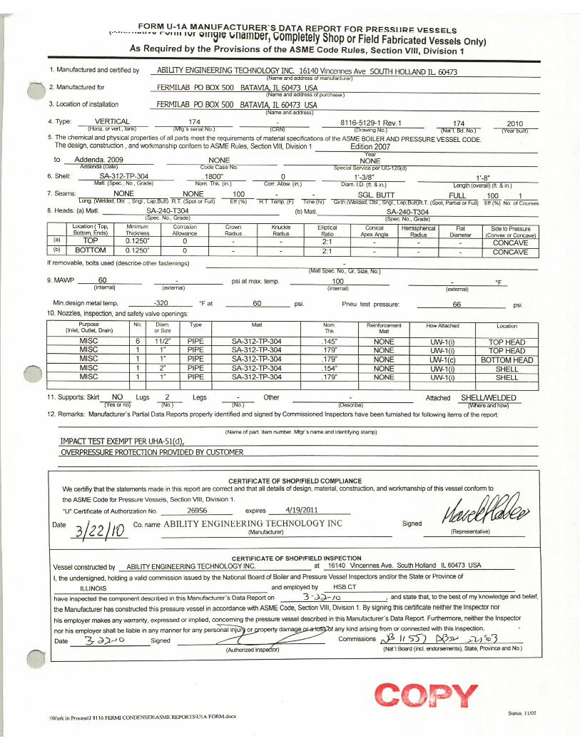
Lab Property Number(s):_____________________________________________________ Lab Location Code: PC4 (obtain from safety officer) Purpose of Vessel(s): To separate nitrogen into gas and liquid. Liquid nitrogen is coolant feed to LAPD condenser. Nitrogen gas is vented by backpressure regulator.
Vessel Capacity/Size: _____________ Diameter: 1’-3/8” Length: 1’-8” Normal Operating Pressure (OP) 1.5 psig MAWP-OP = (60-1.5)= 58.5 PSI List the numbers of all pertinent drawings and the location of the originals. Drawing # Location of Original 8116-5129-1 (by Ability Engineering) _______ DOCDB LARTPC-DOC-599 ____________________ _________________________________ _________________________________________ _________________________________ _________________________________________ _________________________________ _________________________________________ _________________________________ _________________________________________ _________________________________ _________________________________________ 2. Design Verification Is this vessel designed and built to meet the ASME BPVC or “Experiment
Vessel” requirements? Yes___X __ No_____.
If “No” state the standard that was used _________________. Demonstrate that design calculations of that standard have been made and that other requirements of that standard have been satisfied. Skip to part 3 “system venting verification.”
Does the vessel(s) have a U stamp? Yes__X___ No__ ___. If "Yes", complete section 2A; if "No", complete section 2B.
A. Staple photo of U stamp plate below.
Copy "U" label details to the side
Copy data here:
NAT’L BD. 174
60 PSI at 100 F
-320 F at 60 PSI
SERIAL 174
YEAR BUILT 2010
W
RT-1
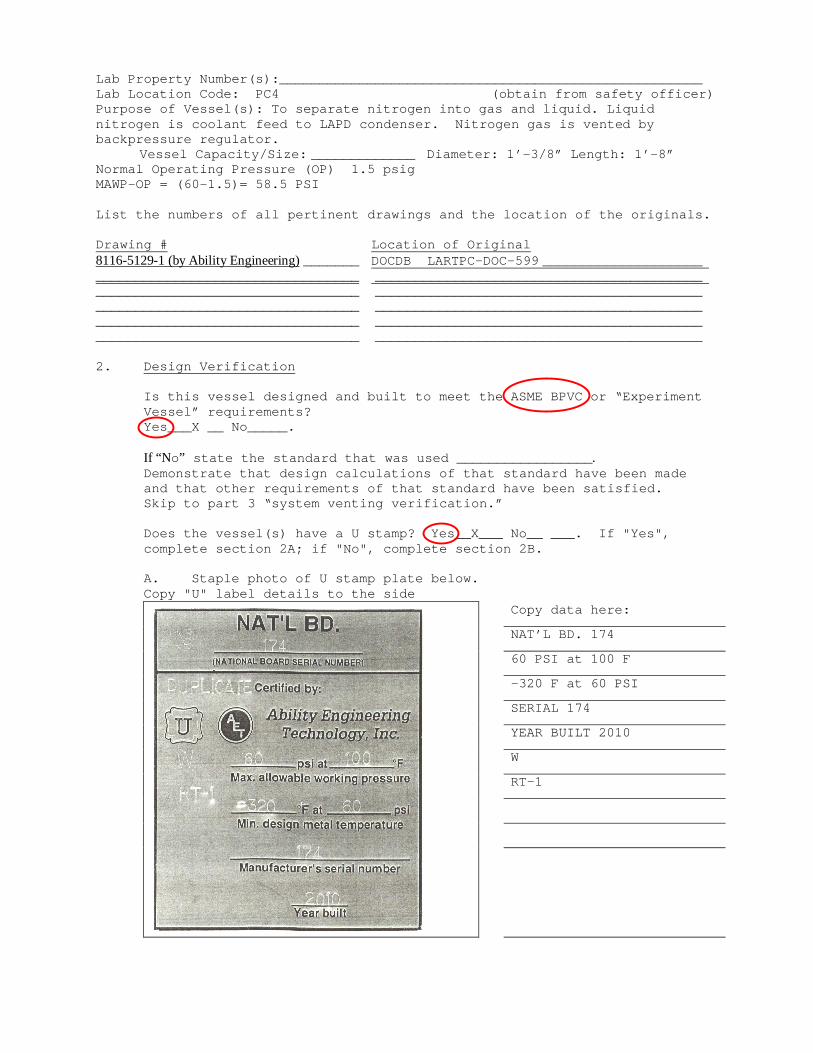
Figure 1. ASME Code: Applicable Sections
2B.
Summary of ASME Code CALCULATION RESULT (Required thickness or stress Reference ASME level vs. actual thickness Item Code Section calculated stress level) ___________________ ____________________________ _____________ vs ___________ ___________________ ____________________________ _____________ vs ___________ ___________________ ____________________________ _____________ vs ___________ ___________________ ____________________________ _____________ vs ___________ ___________________ ____________________________ _____________ vs ___________
THE LAPD CONDENSER IS A CODE STAMPED ASME VESSEL. THIS SECTION IS NOT REQUIRED.
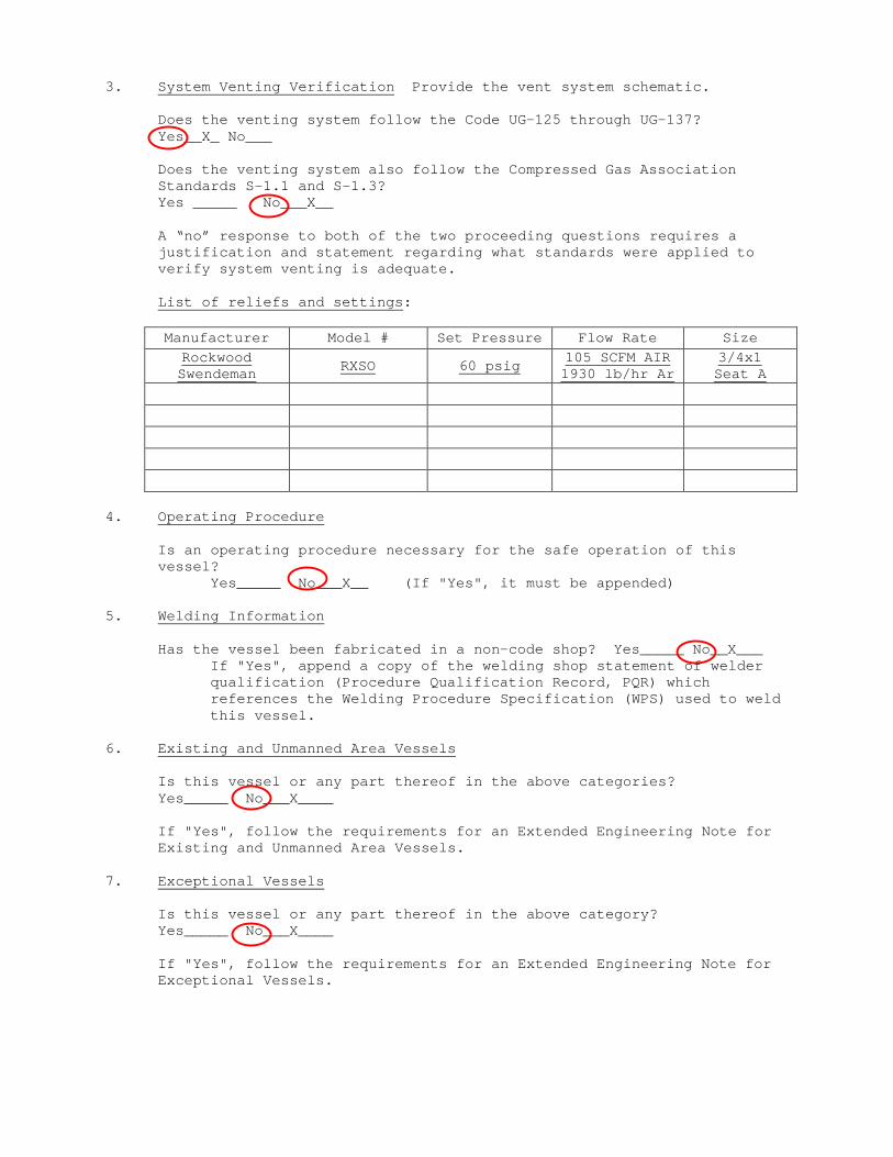
3. System Venting Verification Provide the vent system schematic. Does the venting system follow the Code UG-125 through UG-137?
Yes__X_ No___ Does the venting system also follow the Compressed Gas Association
Standards S-1.1 and S-1.3? Yes _____ No___X__ A “no” response to both of the two proceeding questions requires a
justification and statement regarding what standards were applied to verify system venting is adequate.
List of reliefs and settings:
Manufacturer Model # Set Pressure Flow Rate Size Rockwood Swendeman RXSO 60 psig 105 SCFM AIR
1930 lb/hr Ar 3/4x1 Seat A
4. Operating Procedure Is an operating procedure necessary for the safe operation of this
vessel? Yes_____ No___X__ (If "Yes", it must be appended) 5. Welding Information Has the vessel been fabricated in a non-code shop? Yes_____ No__X___
If "Yes", append a copy of the welding shop statement of welder qualification (Procedure Qualification Record, PQR) which references the Welding Procedure Specification (WPS) used to weld this vessel.
6. Existing and Unmanned Area Vessels Is this vessel or any part thereof in the above categories? Yes_____ No___X____
If "Yes", follow the requirements for an Extended Engineering Note for Existing and Unmanned Area Vessels.
7. Exceptional Vessels Is this vessel or any part thereof in the above category? Yes_____ No___X____
If "Yes", follow the requirements for an Extended Engineering Note for Exceptional Vessels.
Terry Tope – version 6.18.12 1/3
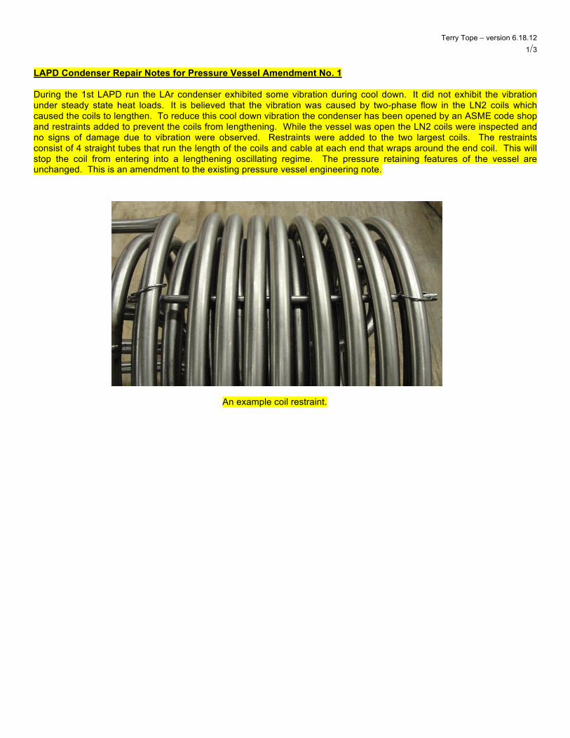
LAPD Condenser Repair Notes for Pressure Vessel Amendment No. 1 During the 1st LAPD run the LAr condenser exhibited some vibration during cool down. It did not exhibit the vibration under steady state heat loads. It is believed that the vibration was caused by two-phase flow in the LN2 coils which caused the coils to lengthen. To reduce this cool down vibration the condenser has been opened by an ASME code shop and restraints added to prevent the coils from lengthening. While the vessel was open the LN2 coils were inspected and no signs of damage due to vibration were observed. Restraints were added to the two largest coils. The restraints consist of 4 straight tubes that run the length of the coils and cable at each end that wraps around the end coil. This will stop the coil from entering into a lengthening oscillating regime. The pressure retaining features of the vessel are unchanged. This is an amendment to the existing pressure vessel engineering note.
An example coil restraint.

Terry Tope – version 6.18.12 2/3
Original ASME code stamp (bottom) and the repair stamp (top).
Terry Tope – version 6.18.12 3/3
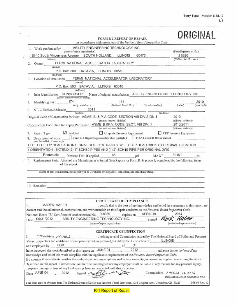
R-1 Report of Repair
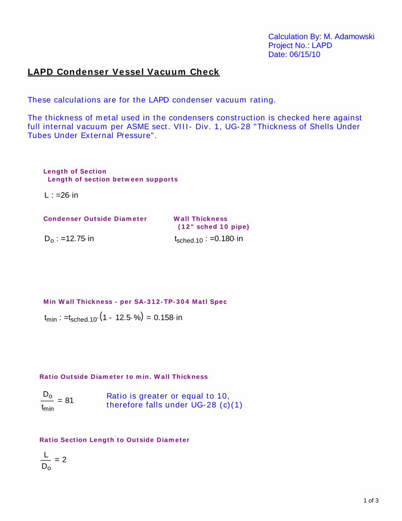
Calculation By: M. AdamowskiProject No.: LAPDDate: 06/15/10
LAPD Condenser Vessel Vacuum Check
These calculations are for the LAPD condenser vacuum rating.
The thickness of metal used in the condensers construction is checked here againstfull internal vacuum per ASME sect. VIII- Div. 1, UG-28 "Thickness of Shells UnderTubes Under External Pressure".
Length of Section Length of section between supports
L 26 in:=
Condenser Outside Diameter Wall Thickness (12" sched 10 pipe)
Do 12.75 in:= tsched.10 0.180 in:=
Min Wall Thickness - per SA-312-TP-304 Matl Spec
tmin tsched.10 1 12.5 %-( ) 0.158 in=:=
Ratio Outside Diameter to min. Wall Thickness
Ratio is greater or equal to 10,therefore falls under UG-28 (c)(1)
Do
tmin81=
Ratio Section Length to Outside Diameter
LDo
2=
1 of 3
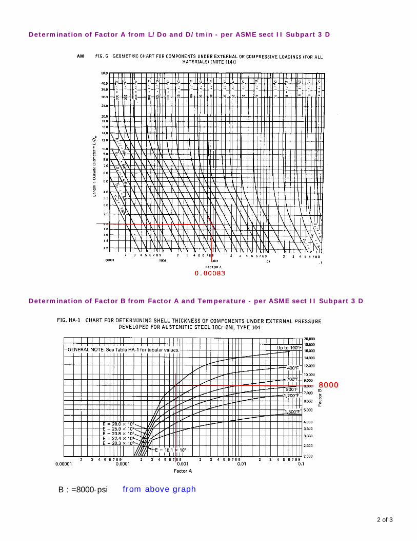
Determination of Factor A from L/Do and D/tmin - per ASME sect II Subpart 3 D
Determination of Factor B from Factor A and Temperature - per ASME sect II Subpart 3 D
B 8000 psi:= from above graph
2 of 3
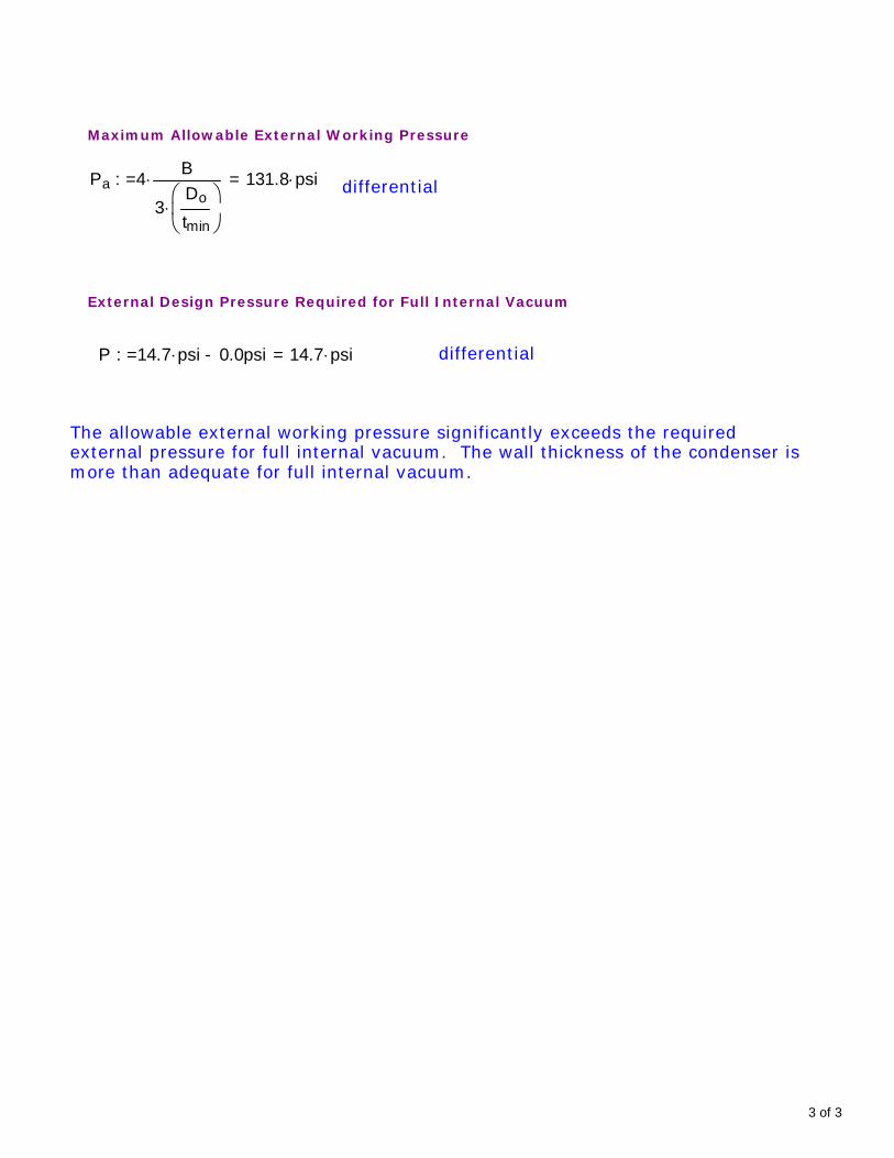
Maximum Allowable External Working Pressure
Pa 4 B
3Do
tmin
131.8 psi=:= differential
External Design Pressure Required for Full Internal Vacuum
P 14.7 psi 0.0psi- 14.7 psi=:= differential
The allowable external working pressure significantly exceeds the requiredexternal pressure for full internal vacuum. The wall thickness of the condenser ismore than adequate for full internal vacuum.
3 of 3
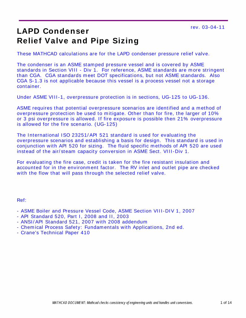
rev. 03-04-11LAPD Condenser Relief Valve and Pipe Sizing
These MATHCAD calculations are for the LAPD condenser pressure relief valve.
The condenser is an ASME stamped pressure vessel and is covered by ASMEstandards in Section VIII - Div 1. For reference, ASME standards are more stringentthan CGA. CGA standards meet DOT specifications, but not ASME standards. AlsoCGA S-1.3 is not applicable because this vessel is a process vessel not a storagecontainer. Under ASME VIII-1, overpressure protection is in sections, UG-125 to UG-136.
ASME requires that potential overpressure scenarios are identified and a method ofoverpressure protection be used to mitigate. Other than for fire, the larger of 10%or 3 psi overpressure is allowed. If fire exposure is possible then 21% overpressureis allowed for the fire scenario. (UG-125)
The International ISO 23251/API 521 standard is used for evaluating theoverpressure scenarios and establishing a basis for design. This standard is used inconjunction with API 520 for sizing. The fluid specific methods of API 520 are usedinstead of the air/steam capacity conversion in ASME Sect. VIII-Div 1.
For evaluating the fire case, credit is taken for the fire resistant insulation andaccounted for in the environment factor. The RV inlet and outlet pipe are checkedwith the flow that will pass through the selected relief valve.
Ref:
- ASME Boiler and Pressure Vessel Code, ASME Section VIII-DIV 1, 2007- API Standard 520, Part I, 2008 and II, 2003- ANSI/API Standard 521, 2007 with 2008 addendum- Chemical Process Safety: Fundamentals with Applications, 2nd ed.- Crane's Technical Paper 410
MATHCAD DOCUMENT: Mathcad checks consistency of engineering units and handles unit conversions. 1 of 14
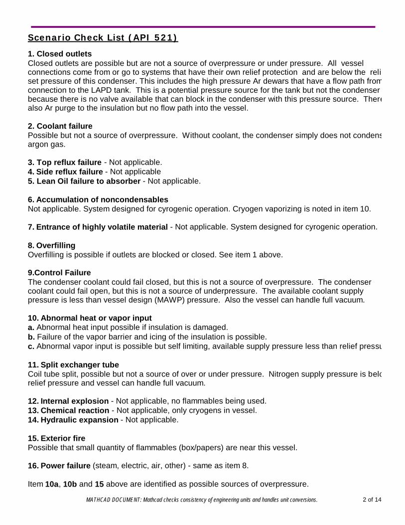
Scenario Check List (API 521)
1. Closed outlets Closed outlets are possible but are not a source of overpressure or under pressure. All vesselconnections come from or go to systems that have their own relief protection and are below the reliefset pressure of this condenser. This includes the high pressure Ar dewars that have a flow path from aconnection to the LAPD tank. This is a potential pressure source for the tank but not the condenserbecause there is no valve available that can block in the condenser with this pressure source. There isalso Ar purge to the insulation but no flow path into the vessel.
2. Coolant failure Possible but not a source of overpressure. Without coolant, the condenser simply does not condenseargon gas.
3. Top reflux failure - Not applicable.4. Side reflux failure - Not applicable5. Lean Oil failure to absorber - Not applicable.
6. Accumulation of noncondensables Not applicable. System designed for cyrogenic operation. Cryogen vaporizing is noted in item 10.
7. Entrance of highly volatile material - Not applicable. System designed for cyrogenic operation.
8. Overfilling Overfilling is possible if outlets are blocked or closed. See item 1 above.
9.Control Failure The condenser coolant could fail closed, but this is not a source of overpressure. The condensercoolant could fail open, but this is not a source of underpressure. The available coolant supplypressure is less than vessel design (MAWP) pressure. Also the vessel can handle full vacuum. 10. Abnormal heat or vapor input a. Abnormal heat input possible if insulation is damaged. b. Failure of the vapor barrier and icing of the insulation is possible. c. Abnormal vapor input is possible but self limiting, available supply pressure less than relief pressure.
11. Split exchanger tubeCoil tube split, possible but not a source of over or under pressure. Nitrogen supply pressure is belowrelief pressure and vessel can handle full vacuum.
12. Internal explosion - Not applicable, no flammables being used.13. Chemical reaction - Not applicable, only cryogens in vessel.14. Hydraulic expansion - Not applicable.
15. Exterior fire Possible that small quantity of flammables (box/papers) are near this vessel. 16. Power failure (steam, electric, air, other) - same as item 8.
Item 10a, 10b and 15 above are identified as possible sources of overpressure.
MATHCAD DOCUMENT: Mathcad checks consistency of engineering units and handles unit conversions. 2 of 14
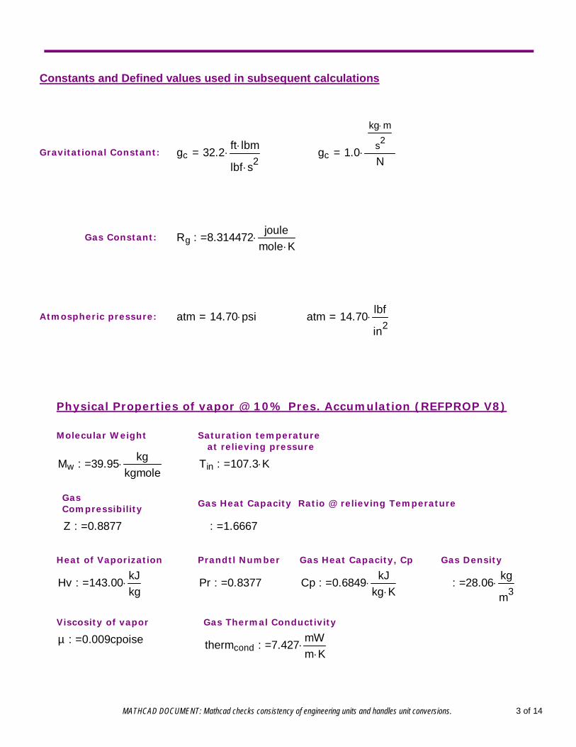
Constants and Defined values used in subsequent calculations
Gravitational Constant: gc 32.2ft lbm
lbf s2= gc 1.0
kg m
s2
N=
Gas Constant: Rg 8.314472joule
mole K:=
Atmospheric pressure: atm 14.70 psi= atm 14.70lbf
in2=
Physical Properties of vapor @ 10% Pres. Accumulation (REFPROP V8)
Molecular Weight Saturation temperature at relieving pressure
Mw 39.95kg
kgmole:= Tin 107.3 K:=
Gas Compressibility
Gas Heat Capacity Ratio @ relieving Temperature
Z 0.8877:= γ 1.6667:=
Heat of Vaporization Prandtl Number Gas Heat Capacity, Cp Gas Density
Hv 143.00kJkg:= Pr 0.8377:= Cp 0.6849
kJkg K:= ρ 28.06
kg
m3:=
Viscosity of vapor Gas Thermal Conductivity
µ 0.009cpoise:= thermcond 7.427mWm K:=
MATHCAD DOCUMENT: Mathcad checks consistency of engineering units and handles unit conversions. 3 of 14
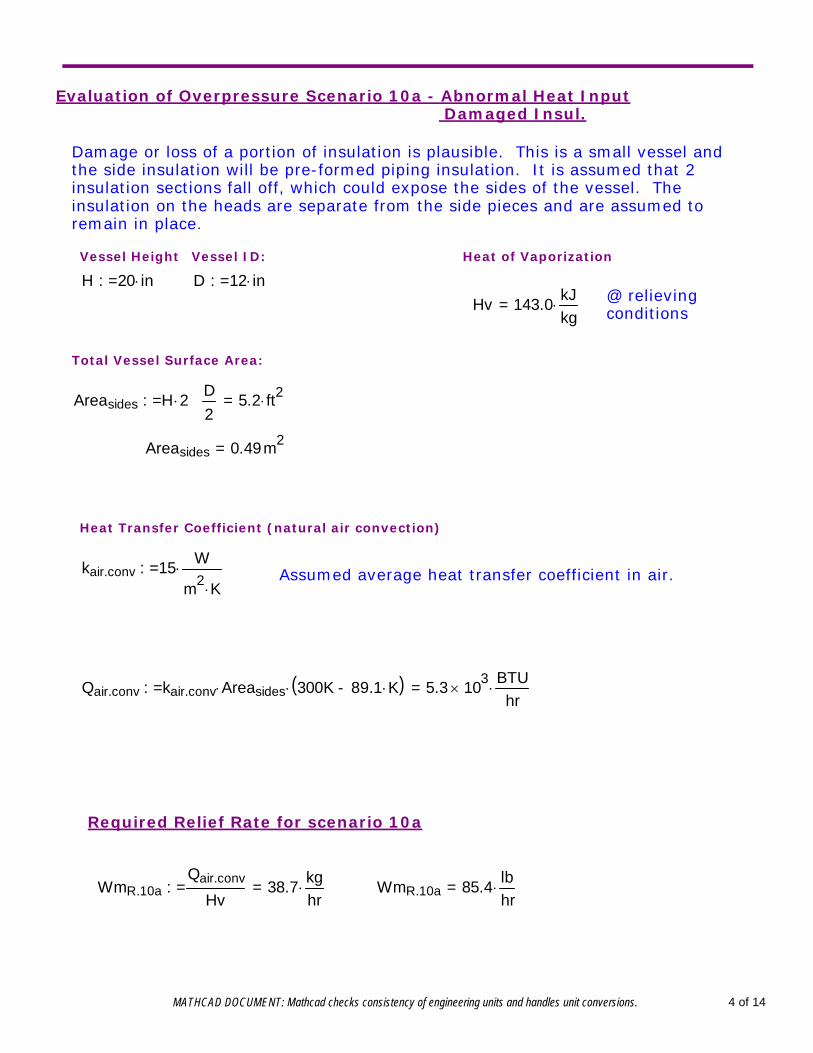
Evaluation of Overpressure Scenario 10a - Abnormal Heat Input Damaged Insul.
Damage or loss of a portion of insulation is plausible. This is a small vessel andthe side insulation will be pre-formed piping insulation. It is assumed that 2insulation sections fall off, which could expose the sides of the vessel. Theinsulation on the heads are separate from the side pieces and are assumed toremain in place.
Vessel Height Vessel ID: Heat of Vaporization
H 20 in:= D 12 in:=@ relievingconditionsHv 143.0 kJ
kg=
Total Vessel Surface Area:
Areasides H 2 π D2
5.2 ft2=:=
Areasides 0.49m2=
Heat Transfer Coefficient (natural air convection)
kair.conv 15 W
m2 K:= Assumed average heat transfer coefficient in air.
Qair.conv kair.conv Areasides 300K 89.1 K-( ) 5.3 103
BTUhr
=:=
Required Relief Rate for scenario 10a
WmR.10aQair.conv
Hv38.7 kg
hr=:= WmR.10a 85.4 lb
hr=
MATHCAD DOCUMENT: Mathcad checks consistency of engineering units and handles unit conversions. 4 of 14
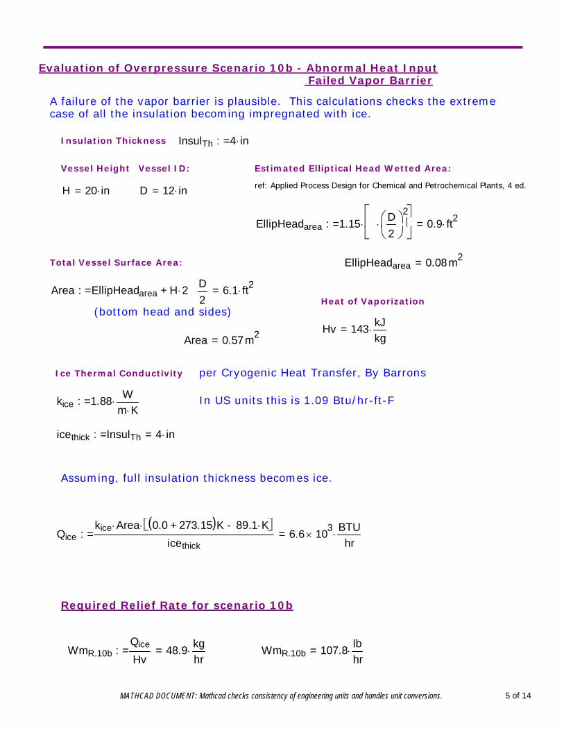
Evaluation of Overpressure Scenario 10b - Abnormal Heat Input Failed Vapor Barrier
A failure of the vapor barrier is plausible. This calculations checks the extremecase of all the insulation becoming impregnated with ice.
Insulation Thickness InsulTh 4 in:=
Vessel Height Vessel ID: Estimated Elliptical Head Wetted Area:
ref: Applied Process Design for Chemical and Petrochemical Plants, 4 ed.H 20 in= D 12 in=
EllipHeadarea 1.15 π D2
2
0.9 ft2=:=
Total Vessel Surface Area: EllipHeadarea 0.08m2=
Area EllipHeadarea H 2 π D2
+ 6.1 ft2=:=Heat of Vaporization
(bottom head and sides)
Hv 143 kJkg=
Area 0.57m2=
Ice Thermal Conductivity per Cryogenic Heat Transfer, By Barrons
kice 1.88 Wm K:= In US units this is 1.09 Btu/hr-ft-F
icethick InsulTh 4 in=:=
Assuming, full insulation thickness becomes ice.
Qicekice Area 0.0 273.15+( )K 89.1 K-
icethick6.6 103
BTU
hr=:=
Required Relief Rate for scenario 10b
WmR.10bQice
Hv48.9 kg
hr=:= WmR.10b 107.8 lb
hr=
MATHCAD DOCUMENT: Mathcad checks consistency of engineering units and handles unit conversions. 5 of 14
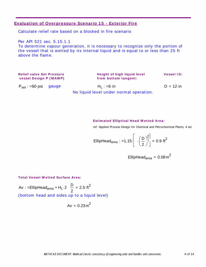
Evaluation of Overpressure Scenario 15 - Exterior Fire
Calculate relief rate based on a blocked in fire scenario
Per API 521 sec. 5.15.1.1To determine vapour generation, it is necessary to recognize only the portion ofthe vessel that is wetted by its internal liquid and is equal to or less than 25 ftabove the flame.
Relief valve Set Pressure vessel Design P (MAWP)
Height of high liquid level from bottom tangent:
Vessel ID:
Pset 60 psi:= gauge HL 6 in:= D 12 in=No liquid level under normal operation.
Estimated Elliptical Head Wetted Area:
ref: Applied Process Design for Chemical and Petrochemical Plants, 4 ed.
EllipHeadarea 1.15 π D2
2
0.9 ft2=:=
EllipHeadarea 0.08m2=
Total Vessel Wetted Surface Area:
Av EllipHeadarea HL 2 π D2
+ 2.5 ft2=:=
(bottom head and sides up to a liquid level)
Av 0.23m2=
MATHCAD DOCUMENT: Mathcad checks consistency of engineering units and handles unit conversions. 6 of 14
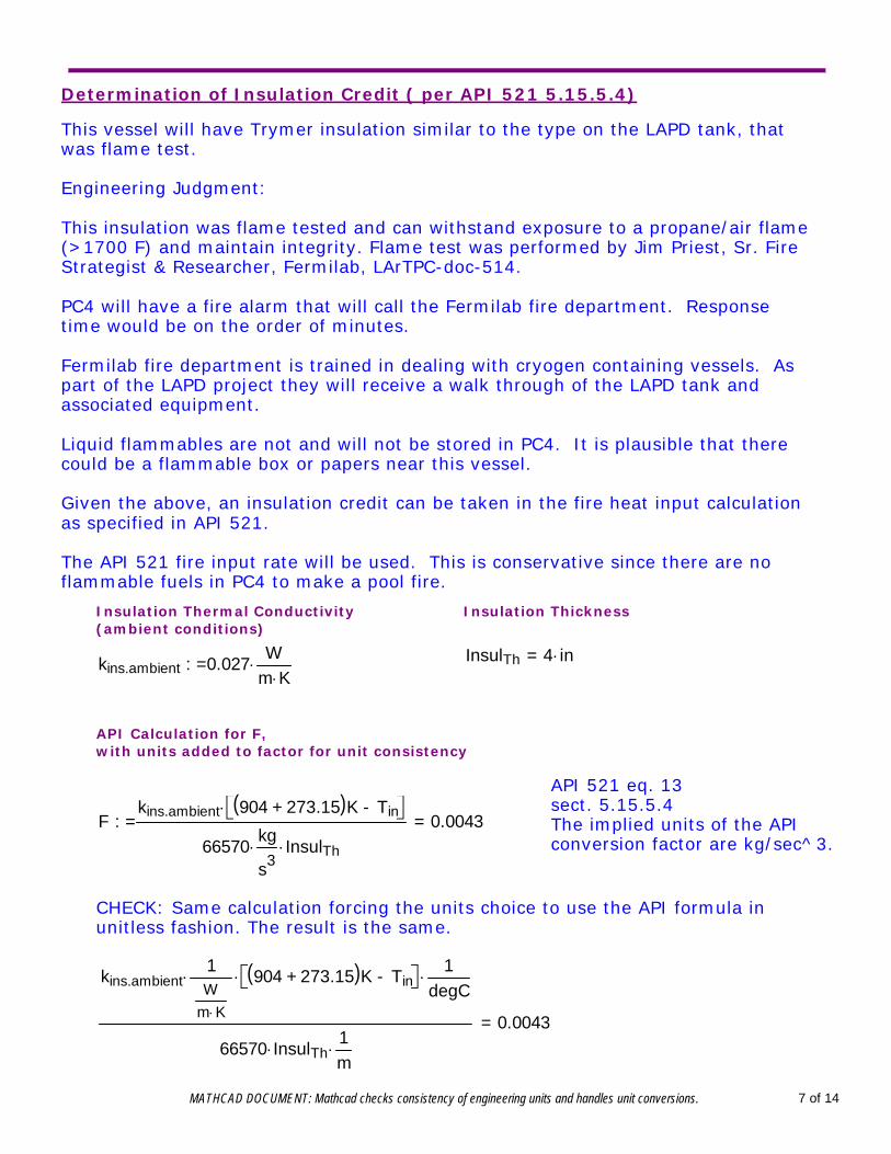
Determination of Insulation Credit ( per API 521 5.15.5.4)
This vessel will have Trymer insulation similar to the type on the LAPD tank, thatwas flame test.
Engineering Judgment:
This insulation was flame tested and can withstand exposure to a propane/air flame(>1700 F) and maintain integrity. Flame test was performed by Jim Priest, Sr. FireStrategist & Researcher, Fermilab, LArTPC-doc-514.
PC4 will have a fire alarm that will call the Fermilab fire department. Responsetime would be on the order of minutes.
Fermilab fire department is trained in dealing with cryogen containing vessels. Aspart of the LAPD project they will receive a walk through of the LAPD tank andassociated equipment.
Liquid flammables are not and will not be stored in PC4. It is plausible that therecould be a flammable box or papers near this vessel.
Given the above, an insulation credit can be taken in the fire heat input calculationas specified in API 521.
The API 521 fire input rate will be used. This is conservative since there are noflammable fuels in PC4 to make a pool fire.
Insulation Thermal Conductivity (ambient conditions)
Insulation Thickness
InsulTh 4 in=kins.ambient 0.027W
m K:=
API Calculation for F,with units added to factor for unit consistency
API 521 eq. 13sect. 5.15.5.4The implied units of the APIconversion factor are kg/sec^3.
Fkins.ambient 904 273.15+( )K Tin-
66570kg
s3 InsulTh
0.0043=:=
CHECK: Same calculation forcing the units choice to use the API formula inunitless fashion. The result is the same.
kins.ambient1W
m K
904 273.15+( )K Tin- 1
degC
66570 InsulTh1m
0.0043=
MATHCAD DOCUMENT: Mathcad checks consistency of engineering units and handles unit conversions. 7 of 14
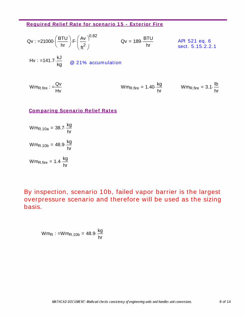
Required Relief Rate for scenario 15 - Exterior Fire
Qv 21000 BTUhr
F Av
ft2
0.82:= Qv 189 BTU
hr= API 521 eq. 6
sect. 5.15.2.2.1
Hv 141.7 kJkg:= @ 21% accumulation
WmR.fireQvHv
:= WmR.fire 1.40 kghr= WmR.fire 3.1 lb
hr=
Comparing Scenario Relief Rates
WmR.10a 38.7 kghr=
WmR.10b 48.9 kghr=
WmR.fire 1.4 kghr=
By inspection, scenario 10b, failed vapor barrier is the largestoverpressure scenario and therefore will be used as the sizingbasis.
WmR WmR.10b 48.9 kghr=:=
MATHCAD DOCUMENT: Mathcad checks consistency of engineering units and handles unit conversions. 8 of 14
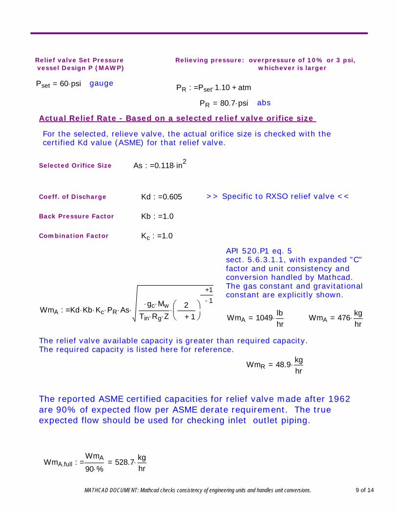
Relief valve Set Pressure vessel Design P (MAWP)
Relieving pressure: overpressure of 10% or 3 psi, whichever is larger
Pset 60 psi= gauge PR Pset 1.10 atm+:=
PR 80.7 psi= abs
Actual Relief Rate - Based on a selected relief valve orifice size
For the selected, relieve valve, the actual orifice size is checked with thecertified Kd value (ASME) for that relief valve.
Selected Orifice Size As 0.118 in2:=
Coeff. of Discharge Kd 0.605:= >> Specific to RXSO relief valve <<
Back Pressure Factor Kb 1.0:=
Combination Factor Kc 1.0:=
API 520.P1 eq. 5sect. 5.6.3.1.1, with expanded "C"factor and unit consistency andconversion handled by Mathcad.The gas constant and gravitationalconstant are explicitly shown.
WmA Kd Kb Kc PR Asγ gc Mw
Tin Rg Z2
γ 1+
γ 1+
γ 1-:=
WmA 1049 lbhr= WmA 476 kg
hr=
The relief valve available capacity is greater than required capacity.The required capacity is listed here for reference.
WmR 48.9 kghr=
The reported ASME certified capacities for relief valve made after 1962are 90% of expected flow per ASME derate requirement. The trueexpected flow should be used for checking inlet outlet piping.
WmA.fullWmA
90 %528.7 kg
hr=:=
MATHCAD DOCUMENT: Mathcad checks consistency of engineering units and handles unit conversions. 9 of 14
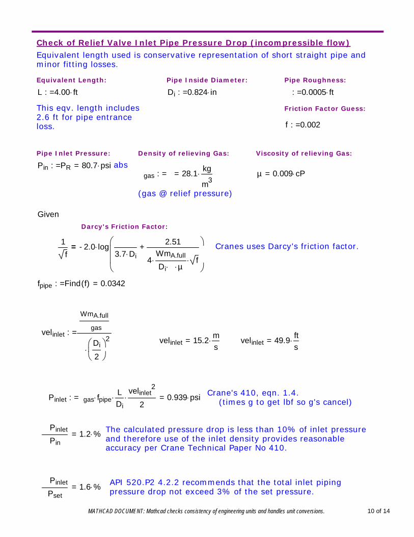
Check of Relief Valve Inlet Pipe Pressure Drop (incompressible flow)Equivalent length used is conservative representation of short straight pipe andminor fitting losses.
Equivalent Length: Pipe Inside Diameter: Pipe Roughness:
L 4.00 ft:= Di 0.824 in:= ε 0.0005 ft:=
This eqv. length includes2.6 ft for pipe entranceloss.
Friction Factor Guess:
f 0.002:=
Pipe Inlet Pressure: Density of relieving Gas: Viscosity of relieving Gas:
Pin PR 80.7 psi=:= absρgas ρ 28.1 kg
m3=:= µ 0.009 cP=
(gas @ relief pressure)
GivenDarcy's Friction Factor:
1
f2.0- log ε
3.7 Di2.51
4WmA.full
Di π µ f
+
= Cranes uses Darcy's friction factor.
fpipe Find f( ) 0.0342=:=
velinlet
WmA.fullρgas
πDi
2
2
:=velinlet 15.2 m
s= velinlet 49.9 ft
s=
Crane's 410, eqn. 1.4. (times g to get lbf so g's cancel)ΔPinlet ρgas fpipe
LDi
velinlet2
2 0.939 psi=:=
The calculated pressure drop is less than 10% of inlet pressureand therefore use of the inlet density provides reasonableaccuracy per Crane Technical Paper No 410.
ΔPinlet
Pin1.2 %=
API 520.P2 4.2.2 recommends that the total inlet pipingpressure drop not exceed 3% of the set pressure.
ΔPinlet
Pset1.6 %=
MATHCAD DOCUMENT: Mathcad checks consistency of engineering units and handles unit conversions. 10 of 14
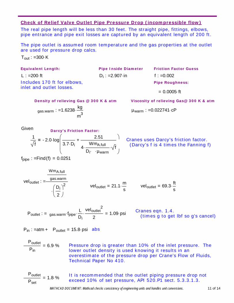
Check of Relief Valve Outlet Pipe Pressure Drop (incompressible flow)The real pipe length will be less than 30 feet. The straight pipe, fittings, elbows,pipe entrance and pipe exit losses are captured by an equivalent length of 200 ft.
The pipe outlet is assumed room temperature and the gas properties at the outletare used for pressure drop calcs.
Tout 300 K:=
Equivalent Length: Pipe Inside Diameter Friction Factor Guess
L 200 ft:= Di 2.907 in:= f 0.002:=Includes 170 ft for elbows,inlet and outlet losses.
Pipe Roughness:
ε 0.0005 ft=
Density of relieving Gas @ 300 K & atm Viscosity of relieving Gas@ 300 K & atm
ρgas.warm 1.6238kg
m3:= µwarm 0.022741 cP:=
Given Darcy's Friction Factor:
1
f2.0- log ε
3.7 Di2.51
4WmA.full
Di π µwarm f
+
= Cranes uses Darcy's friction factor. (Darcy's f is 4 times the Fanning f)
fpipe Find f( ) 0.0251=:=
veloutlet
WmA.fullρgas.warm
πDi
2
2
:=veloutlet 21.1
ms
= veloutlet 69.3fts=
Cranes eqn. 1.4. (times g to get lbf so g's cancel)ΔPoutlet ρgas.warm fpipe
LDi
veloutlet2
2 1.09 psi=:=
Pin atm ΔPoutlet+ 15.8 psi=:= abs
ΔPoutlet
Pin6.9 %= Pressure drop is greater than 10% of the inlet pressure. The
lower outlet density is used knowing it results in anoverestimate of the pressure drop per Crane's Flow of Fluids,Technical Paper No 410.
It is recommended that the outlet piping pressure drop notexceed 10% of set pressure, API 520.P1 sect. 5.3.3.1.3.
ΔPoutlet
Pset1.8 %=
MATHCAD DOCUMENT: Mathcad checks consistency of engineering units and handles unit conversions. 11 of 14
REFERENCE MATERIAL
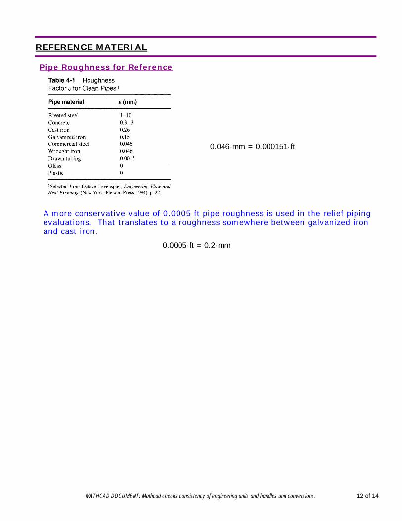
Pipe Roughness for Reference
0.046 mm 0.000151 ft=
A more conservative value of 0.0005 ft pipe roughness is used in the relief pipingevaluations. That translates to a roughness somewhere between galvanized ironand cast iron.
0.0005 ft 0.2 mm=
MATHCAD DOCUMENT: Mathcad checks consistency of engineering units and handles unit conversions. 12 of 14
Use of Inlet Conditions for Ratio of Specific Heats, k
The eight edition of API 520 contradicts itself in the published standard over the useof the ratio of specific heats at standard conditions or inlet relieving conditions.
API 520 takes the ideal gas equation for choked flow and separates out theestimated critical flow pressure ratio into a separate factor to which they attachlumped unit conversion factors, API refers to as C.
In the 6th edition of 520, C was defined as "coefficient determined from anexpression of the ratio of specific heats of the gas or vapor at standard conditions.
Starting with the 7th edition of 520, C was defined as "a function of the ratio of theideal gas specific heats (k=Cp/Cv) of the gas or vapor at inlet relieving temperature".Other references to C were left unchanged, including indication that only C atstandard conditions could be used.
API responded to an request for interpretation on this apparent contradiction. API'sreply, was "Yes. Section 3.6.2 (7th ed) recommends that the ratio of specific heats, k, in the sizing equations should be determined at the inlet relieving conditions. Thisis a departure from previous editions, which said that k should be based on standardconditions (i.e. 60 F and atmospheric pressure)". Between the 7th and 8th, thesizing formula and definition of C moved from section 3.6.2 to section 5.6.3.1.1.
The "new" assumption of at relieving conditions was evaluated by A. Shackelfordand reported in "Using the Ideal Gas Specific Heat Ratio for Relief Valve Sizing",Chem. Eng. 110, No. 12, 54-59, Nov. 2003. His work indicated that the heat capacityratio could be used as an estimate of the isentropic expansion coefficient to providea good estimate of the mass flux through a nozzle.
Relief conditions near the critical point or at very high pressure are poorlyrepresented by these assumptions and special evaluation is required. API 520,appendix B provides guidance.
MATHCAD DOCUMENT: Mathcad checks consistency of engineering units and handles unit conversions. 13 of 14
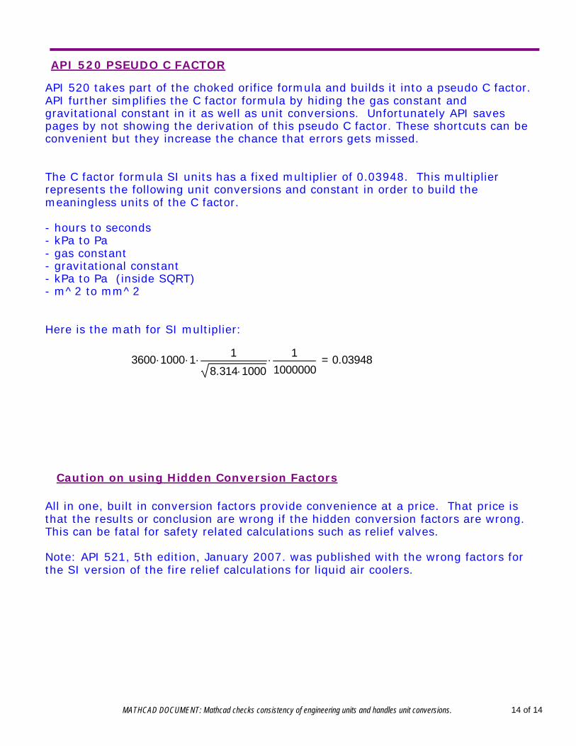
API 520 PSEUDO C FACTOR
API 520 takes part of the choked orifice formula and builds it into a pseudo C factor.API further simplifies the C factor formula by hiding the gas constant andgravitational constant in it as well as unit conversions. Unfortunately API savespages by not showing the derivation of this pseudo C factor. These shortcuts can beconvenient but they increase the chance that errors gets missed.
The C factor formula SI units has a fixed multiplier of 0.03948. This multiplierrepresents the following unit conversions and constant in order to build themeaningless units of the C factor.
- hours to seconds- kPa to Pa- gas constant- gravitational constant - kPa to Pa (inside SQRT)- m^2 to mm^2
Here is the math for SI multiplier:
3600 1000 1 1
8.314 1000
11000000 0.03948=
Caution on using Hidden Conversion Factors
All in one, built in conversion factors provide convenience at a price. That price isthat the results or conclusion are wrong if the hidden conversion factors are wrong.This can be fatal for safety related calculations such as relief valves.
Note: API 521, 5th edition, January 2007. was published with the wrong factors forthe SI version of the fire relief calculations for liquid air coolers.
MATHCAD DOCUMENT: Mathcad checks consistency of engineering units and handles unit conversions. 14 of 14