lab validation of pv solar inverter control as … validation of pv solar inverter control as...
TRANSCRIPT

1
Lab Validation of
PV Solar Inverter Control as
STATCOM (PV-STATCOM)
Rajiv K. Varma and Ehsan Siavashi The University of Western Ontario
London, ON, CANADA

Novel Concept
Utilization of PV Solar Farm in Night and Day
as STATCOM!
Termed as PV-STATCOM patent pending

Concept of Control:
PV Solar Farm Inverter as STATCOM
3
𝑄 = 𝑆2 − 𝑃2
Nighttime: Entire Inverter Capacity Utilized for STATCOM
Daytime: Remaining Inverter Capacity Utilized for STATCOM

PV-STATCOM Technology
• Applications - Motivation
• Enhancement of Power Transfer Capacity
• Improvement of Neighbouring Wind Farm Connectivity
• Lab Validation
• Inverter for PV Solar system
• Inverter as STATCOM
• Inverter as PV-STATCOM

Applications
of
PV-STATCOM Technology
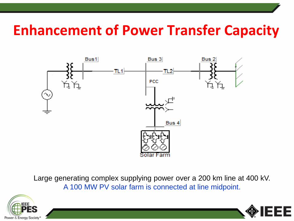
Large generating complex supplying power over a 200 km line at 400 kV.
A 100 MW PV solar farm is connected at line midpoint.
Enhancement of Power Transfer Capacity

Increasing transmission capacity
• A 100 MW solar farm as PV-STATCOM can
increase transmission limit by
– 168 MW in the night, and
– 142 MW during the day time even at high solar power
generation (~ 94MW)
• Cost of PV-STATCOM Controller: ~ $200k
• Cost of equivalent SVC/ STATCOM : ~ $ 50 Million

Improvement of Neighbouring Wind Farm Connectivity
• 4.5 MW PV solar farm
• 15 MW wind farm

• A 4.5 MW solar farm as PV-STATCOM helps to connect an additional 7 MW of wind power in the night bringing ~ $2.1 Million new revenues annually for wind farm
• Similar benefits also achievable to substantial degree during daytime
• Cost of new Solar Farm Controller several orders of magnitude lower than a conventional STATCOM
Improvement of Neighbouring Wind Farm Connectivity

Lab Validation prior to
Field Implementation in an Ontario
Utility Network
- voltage regulation
- power factor correction

Test System
11
10 kW Inverter

PV-STATCOM
12
Analog Channel
Digital Channel Sending six firing
pulses to GTDI card at the rear
end of RTDS
RTDS
DDAC Analog Channel
CLP1103
DS1103
dSPACE Hardware
Sub-D type Connector
GTDI Card
Firing Pulse
Coming in to RTDS
RTDS studies
PSCAD/EMTDC
studies
Hardware-In-Loop
(HIL)
Laboratory validation
studies
Stages of Testing

13
Conceptual/Actual Development of PV-STATCOM
6 –pulse
IGBT Bridge
Conventional PV
Controller
PV Inverter
PV-STATCOM
Controller
PV-STATCOM

14
PV-STATCOM Control Panel

Inverter Control
for
PV Solar System

PV Simulator Characteristic
16

17
4kW Active Power
2.7kW Active Power
PCC Voltage
Inverter Current
Real Power Control – Steady State Operation

18
PCC Voltage
Inverter Current
Step Change in Real Power from 4 kW to 6 kW Reactive Power ~ 0 VAr
Implemented by Step change in DC Voltage ~ 423 Vdc (4kW) to 400 Vdc (6kW)
Real Power Control - Transient Response

Inverter Control
for
STATCOM

STATCOM Test Voltage Regulation 20
Inductive Mode Capacitive Mode
PCC Voltage
Inverter Current

STATCOM Test Voltage Regulation 21
Transient Response
PCC Voltage
Inverter Current
Condition: Real Power ~ 0 kW
Reactive Power ~ -6 to +6 kVAr
Step change of Reference Voltage ~ 0.92 PU (110V rms) to 1.07 (128V rms)

Inverter Control
for
PV-STATCOM

PV-STATCOM Test Voltage Regulation 23
Inductive Mode
Capacitive Mode
PCC Voltage
Inverter Current

PV-STATCOM Test Voltage Regulation 24
Transient Response
PCC Voltage
Inverter Current
Real Power ~ 6 kW
Change in Reactive Power : -6 to +6 kVAr
Step change of Reference Voltage ~ 0.92 PU (110Vrms) to 1.07 (128Vrms)

PV-STATCOM Test Power Factor Correction 25
Transient Response
PCC
Voltage
PV Real Power ~ 3 kW
Load Power ~ Active: 6 kW , Reactive: +9 kVAr (Inductive)
Step change in Power Factor ~ From 0.32 lag to Unity
Inverter Current
Load Current
Grid Current
Grid Voltage Active
power
(phase A)
Grid
Current
(rms)
Grid
Inverter
Load
Inverter
Load
Reactive
power
(phase A)
Grid
Inverter
Load
Grid Power Factor
Response time < 1 cycle

PV-STATCOM Test Power Factor Correction 26
Transient Response
PCC
Voltage
PV Real Power ~ 3 kW
Load Power ~ Active: 6 kW , Reactive: -3 kVAr (Capacitive)
Step change of Power Factor ~ From 0.707 leading to Unity
Inverter Current
Load Current
Grid Current
Grid Voltage
Active
power
(phase A)
Grid
Current
(rms)
Grid
Inverter
Load
Inverter
Load
Reactive
power
(phase A)
Grid
Inverter
Load
Grid Power Factor
Response time < 1 cycle

Control Coordination of Two PV-STATCOMs 27

Western University Power System Lab 28

Novel Control of PV solar farm as STATCOM
(PV-STATCOM)
Controls validated in Lab for voltage regulation and
power factor correction on single 10 kW inverter
Potential to bring:
• New revenues to solar farms during nights and day
• Better network performance for utilities
29
Conclusions

Acknowledgment
Financial Support:
• Ontario Centers of Excellence (OCE) • Ontario Power Authority (OPA) • Independent Electricity System Operator (IESO) • Hydro One • Bluewater Power, Sarnia • NSERC Lab Support: • Mahendra A.C.

Thank You
Questions? 31